1. Introduction
Software development is a laborious process requiring knowledge of Programming Languages and various technologies. One of the major decisions we need to take is to choose the appropriate programming language. In recent decades, programming languages have advanced significantly. A lot of research in the field of programming languages is concerned with the design and implementation of a language, as we want to express programming ideas in a better and user-friendly way. Research in programming languages is an endless activity and the core of computing. We can expect new language features, concepts, paradigms, and programming mechanisms in the future.
Despite advances in programming languages and platforms, most software is developed at a low level of abstraction relative to the concepts used by application programmers. This semantic gap is reduced by Domain-Specific Languages (DSLs) [
1]. These languages cover the essential characteristics of the problem space in a way that they separate them from the details of the specific solution space [
2]. These languages, when compared to general-purpose languages (GPLs), support a higher level of abstraction, and are closer to the problem domain than the implementation domain [
3]. DSLs focus on domain abstractions, which empower end-users to program directly with concepts from the problem domain [
4,
5]. The benefits of using DSLs are increased flexibility, productivity, reliability, and usability, which have been demonstrated in empirical studies [
6,
7,
8].
Moreover, Domain-Specific Modeling Languages (DSMLs) [
9,
10,
11,
12,
13] overlap in many ways with DSLs. These languages specify programs with models, and use visual blocks that raise the level of abstraction further [
14,
15]. The abstract language syntax is usually defined by a metamodel that describes the language elements, the connections between them, and the structural rules that limit the model elements and their combinations [
16,
17].
DSMLs are suitable for use in specific areas [
18,
19,
20,
21,
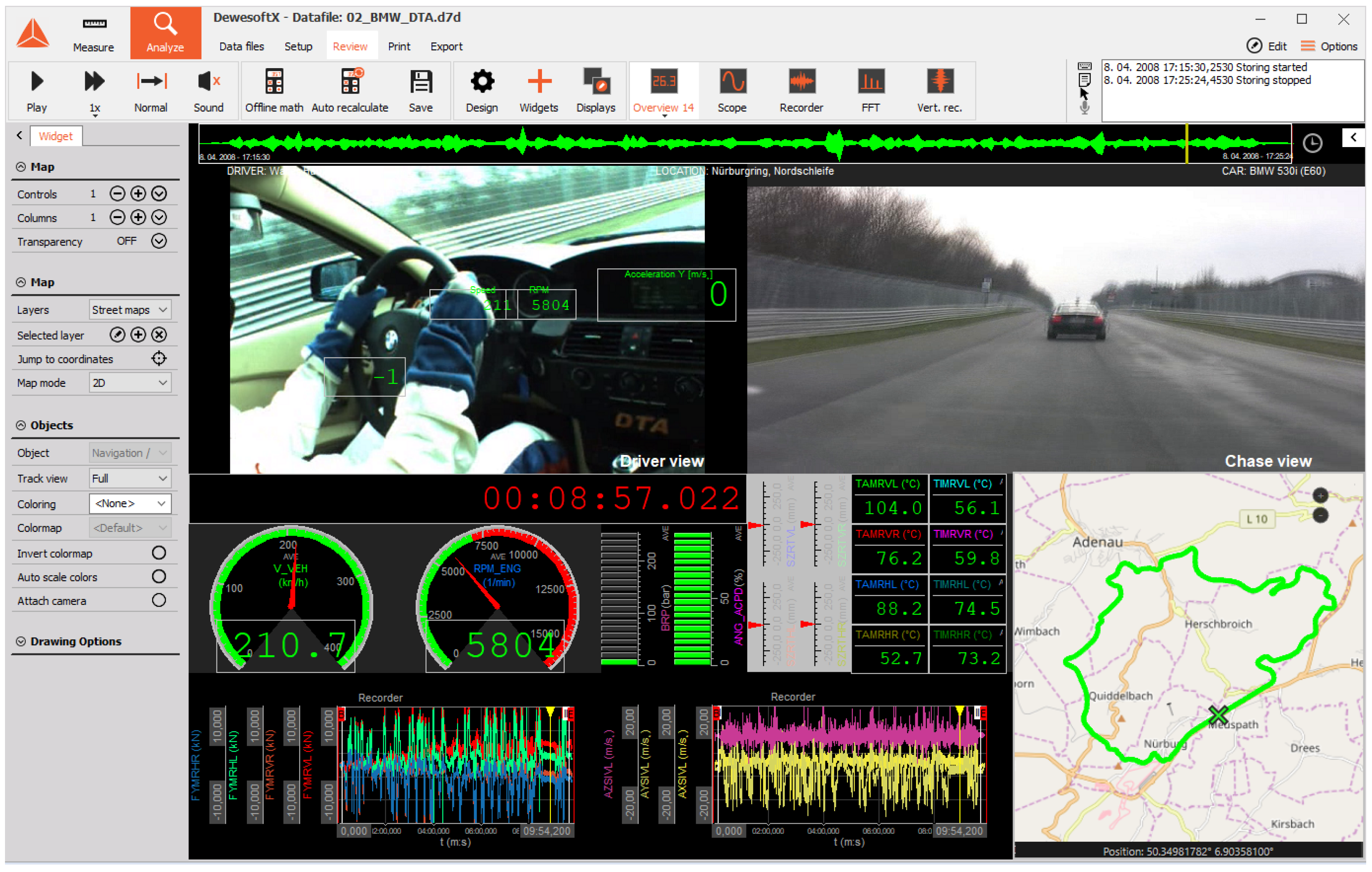
22]. Dewesoft measurement systems [
23], together with the Dewesoft X software package, are used to capture, process, and later analyze the measured data, using the domain-specific modeling language Sequencer [
24,
25,
26] for the creation of measurement procedures. With the mentioned language, the end-users can create measurement procedures performed on the measuring system efficiently without professional computer knowledge. Further in this paper, we refer to DSML end-users as domain experts.
The Sequencer language has been in use since 2010. More than 1000 domain experts use Dewesoft with the DSML Sequencer daily. Interacting with them shows customers’ needs and desires for new possibilities of using our products [
27]. As a consequence, the last improvement involved the development of a new language called RT-Sequencer. Our previous modeling language, Sequencer, was adapted to support, besides data acquisition (DAQ), another problem domain. RT-Sequencer now supports the creation of real-time (RT) procedures that run on Dewesoft controllers. Therefore, this paper presents the experience with DSML evolution and the implementation details behind the new language RT-Sequencer.
The recent systematic mapping study [
28] outlines that the DSL community focuses more on developing new techniques/methods rather than providing empirical evidence. Besides, almost no attention is given to the maintenance and evolution of DSLs in the literature, as argued in another study by Tolvanen and Kelly [
29]. This paper tries to contribute to this field by presenting RT-Sequencer, a successor of the Sequencer [
24,
27]. On the other hand, in another DSL literature review [
30], authors report that most researchers experienced DSL’s evolution, and that the evolution of a DSL affected the success of their DSL [
30]. As shown in the findings from the same study [
30], 40% of DSLs evolved due to the support of new domains, which was the case of Sequencer as well.
Our evolved DSML, named RT-Sequencer, now also supports, besides another problem domain, advanced programming concepts (multi-processes, semaphores, etc.). These concepts are known to programming engineers but not to domain experts that use Sequencer (e.g., measurement engineers in the automotive industry). To support these concepts, several changes were introduced, not only to Sequencer, but also to the whole process of defining measurement sequences. As shown in this paper, we now distinguish two categories of DSML end-users: domain experts and advanced end-users. While domain experts use RT-Sequencer in almost the same manner as Sequencer, advanced end-users are newly introduced to the measurement process with RT-Sequencer. Advanced end-users use the above mentioned concepts and prepare the modeling environment for domain experts. To do that, advanced end-users require greater flexibility in the development phase. Therefore, the domain-specific modeling language RT-Sequencer was opened in a way that the GPL code can be used to create the new constructs needed for a more specific domain on Real-Time Control (RTC) systems, and have the possibility to adapt and optimize the execution code for a particular task.
The remainder of this paper is organized as follows. Background on the previous version of a DSML (Sequencer) is given in
Section 2.
Section 3 discusses the motivation for our work. The architecture and other generalized ideas for the RT-Sequencer are described in
Section 4. The relation between Sequencer and its successor RT-Sequencer is discussed in
Section 5. Implementation details for RT-Sequencer are given in
Section 6. Evaluation with the domain expert and advanced end-user perspectives are illustrated in
Section 7. The related work is discussed in
Section 8. Finally, the concluding remarks are summarized in
Section 9.
3. The Motivation for the Evolution of Domain-Specific Modeling Language
The Sequencer language [
24] is used for data acquisition, processing, analysis, and storage in various industries (automotive, aerospace, railway, space, industry, etc.). A variety of purposes of Dewesoft together with DSML Sequencer was shown from tests in the automotive industry [
27] to aerospace telemetry [
25]. Those examples show that a domain expert can develop their applications efficiently in Sequencer [
31].
Several extensions to DSML Sequencer have been made since the integration of Sequencer in Dewesoft. For example, in our previous paper, we showed that programming tools (e.g., debugger, testing tool, refactoring tool) are also needed for domain experts to ensure the proper functioning of the DSML models. Our study [
27] reported that domain experts without programming knowledge adopt such tools quickly, although not being experts or engineers in Programming or Computer Science.
However, none of the previously developed features needed such drastic modifications in the architecture of the Sequencer language as the one presented in this paper. Besides support for another problem domain, several other reasons drove these newly introduced modifications. After all the years of Sequencer use, some end-users would like to see new concepts, such as multi-processing, semaphores, or other synchronization and locking primitives inside Sequencer. Some special access to the lower level of programming language and, in some cases, special processor instructions are needed to support those mechanisms. Introducing new visual blocks, each representing a new feature in the Sequencer, would be a logical step forward. On the other hand, introducing new visual blocks that would support these concepts still would not be enough in the future. Therefore, we decided to open our DSML Sequencer so that domain experts can insert GPL code at a specific point (define new visual blocks with a predefined programming interface), as introduced in the following sections.
Although some would say this contradicts the DSLM language, where we want to make a distinction between domain experts and programmers, we extended the DSML language with GPL constructs. GPL constructs may represent a generalization of the benefits of DSML languages, but are still sufficiently domain-oriented. This RT-Sequencer functionality of defining new visual blocks can only be used by end-users familiar with computer programming, offering them greater language flexibility.
Motivating Problem Domain: Support for Hard Real-Time Control Systems
As presented in
Section 2, Dewesoft and Sequencer were used by customers only for the DAQ domain. However, with the RT-Sequencer, we wanted to expand to the new area of use, so that Dewesoft measurement equipment and software could also be used for running and controlling RT systems (e.g., Dewesoft’s IOLite,
https://dewesoft.com/products/daq-and-control-systems/iolite-lx (accessed on 12 October 2022)).
Firstly, let us introduce Real-Time Control (RTC) systems. RTC systems can be divided into soft and hard RT controllers depending on the response requirements [
32]. The first are those whose responsiveness is not so essential, and response time will not affect the system’s operation critically. An example of such a system is the one that includes the existing DSML, Sequencer. The second group comprises hard real-time controllers (RTCs). For these, responsiveness is crucial, and non-responsiveness can lead to critical error over time (e.g., it can lead to injuries, loss of life, significant financial loss, etc.). The essential features of such systems are guaranteed and predictable response times, exceptional reliability and safety, low response time, and a stable frequency loop. For this reason, it is so vital that programmers can use GPL language to implement the most performance-sensitive parts of programming algorithms. The GPL code should be more efficient than the code generated with the DSML generator. We can produce hand-optimized code perfectly tuned for a particular hardware setup. Because Dewesoft is used for time-critical applications, the new version of Sequencer (RT-Sequencer) must be designed as a hard RTC system.
Classic RTC systems are usually programmed with Programmable Logic Controllers (PLCs) [
33], which are most often associated with a slower solution to the problem and additional costs, as a domain expert in a particular domain does not know how to program such controllers. Because of this, reaching out to additional people with programming skills is necessary. In our case, we enable additional end-users, advanced end-users with skills in GPL languages, to define a hard RTC system. On the other hand, it is also essential to preserve an end-user, a domain expert, who can determine the controlling procedure on the RTC system without knowledge of programming in GPL.
To sum up, a major motivation in the construction of the new Sequencer was the connection of two types of systems: DAQ and RTC systems. DAQ systems allow faster data capture, timing correlation, and typically better accuracy of input data. On the other hand, RTC systems are based on as short response latency (as possible). In our case, we would like to have a system with a higher sampling frequency (e.g., 1 MHz) and a lower response time (e.g., 1 kHz), which, in practice, means that we would capture more data at the same time in the control cycle (e.g., 1000 data per scanning cycle). For this reason, some direct interrupts and particular optimization are needed at the GPL level, which requires having the direct facility to make arbitrary system calls to combine both worlds.
5. Evolution of Our Domain-Specific Modeling Language
To understand the relation between Sequencer and its successor RT-Sequencer better,
Figure 4 depicts the connection between those two languages. There are three levels of modeling in
Figure 4. The first level defines the
metamodeling level, the second is
modeling level and the third is the
generated code level, as depicted on the right side of
Figure 4.
The first level, indicated with M2, contains a metamodel, which is an abstraction that combines the properties of instances (models) that appear on the second level. The metamodel is constructed with metadata that define the properties and features of the language. Both our languages differ in the supported problem domains, as shown in
Figure 4. While Sequencer supports the DAQ domain, RT-Sequencer was developed upon artifacts reused from Sequencer, and in this manner supports, besides the RTC domain, also the DAQ domain. According to Mernik et al. [
2], RT-Sequencer can be classified in
piggyback pattern for language design if we consider that Sequencer has used an existing language partially. Different concepts were reused, representing visual blocks and connections, predefined concepts, local/global model variables, etc. However, new functionalities (e.g., the ability to define new concepts) forced us to extend Sequencer, and implement a much more complex metamodel for RT-Sequencer, that supports another domain in a way that new constructs can be defined.
On the second level models appear in both languages. Models represent conceptual solutions from the problem domain, and correspond to the metamodel defined in level M2. In
Figure 4, we can observe a slightly more complex structure for RT-Sequencer. While end-users define a single model in Sequencer, we need to define two models on this level for RT-Sequencer. In sublevel M1.1, we specify new language constructs; in sublevel M1.2, we define a model. Models in sublevel M1.1 expand our metamodels with new constructs, since the RT-Sequencer metamodel is defined in a way that it is possible to extend a language with new features (
self-extension [
35] in
Figure 4). Besides, GPL code is used to define the logic of this new language. Consequently, the model on M1.2 is constructed using elements defined in the metamodel (level M2) and the model on level M1.1. With this separation into two models (on sublevels M1.1 and M1.2), RT-Sequencer supports multi-level modeling on this level [
36,
37,
38], which will be discussed later in this paper.
The last level is the generated program level (indicated by M0), where we use transformation rules for individual elements from the model and a transformation engine to produce the programming code, which will, finally, be executed inside the Dewesoft system.
Figure 4 shows that domain experts can make RTC programs and DAQ programs inside the RT-Sequencer. Note that the RTC program combines both domains, the RTC and DAQ domains, since the RT-Sequencer language is based on the Sequencer as described in the M2 level.
The above details of our extension are connected with both languages’ structures. Note, other means of a language (language framework, etc.) were also reused from Sequencer, and incorporated in our new language RT-Sequencer, but are a bit outside of the scope of this paper.
6. Modeling Language Implementation
In this section, the implementation of the domain-specific modeling language RT-Sequencer will be described from several perspectives. We start with the design of the modeling language with a description of the abstract syntax with the metamodel. The following subsection contains details of the model’s transformation to source code. The modeling tool implementation details for different end-users are given in the following subsection. The details of the execution framework are provided at the end.
6.1. Modeling Language
The domain-specific modeling language RT-Sequencer was designed based on the previous Sequencer language, where we performed the initial domain analysis [
24]. For the Sequencer, we defined the domain-specific language concepts and terminology upon our previous Dewesoft application in the field of DAQ and the end-users needs from different areas of Dewesoft usage. Since the RT-Sequencer is used to model another domain, we added constructs to the new language to support the definition of sequences for RTC systems. As will be shown further in this section, these new constructs enable advanced end-users to prepare visual blocks with the C++ language. With this notion, we achieved openness, generalization, and easy scalability, according to the needs of the domain. As a result, the domain expert can model with both pre-prepared visual blocks by RT-Sequencer and visual blocks defined by the advanced end-user.
6.1.1. Support for Real-Time Tasks
A new domain, RTC systems, has shown the need for multi-process programming. We added these mechanisms to the language for creating, and later implementing, several tasks, which can be of different types:
Normal task,
Periodical task, and
Event task.
Those tasks can run in parallel to control different RT processes at the same time (see
Figure 5). The normal task starts when the program is started. A system can have one or more normal tasks running all the time. Typically, RTC systems have at least two tasks. A task where the main program is executed, while the second task takes care of safety management in the case of unpredictable events (shut down the execution according to the necessary procedure). Moreover, the normal tasks explicit feature is that, when all normal tasks are completed, all other processes (periodic and event tasks) are interrupted and completed. This also ends the whole RTC program.
The second type is a periodic task, that starts at a specific period whenever the time for the periodic task expires. The time period can be set randomly in ms. An example of such a task is if you want to read the bridge steel structure temperature periodically every minute, or check the water level in the river every day.
Tasks can also be started when a specific external event or trigger occurs (e.g., when a certain signal has been raised and values need to be calculated). These events are detected within a special event loop. The event loop ensures the detection of events and the starting of tasks.
6.1.2. Metamodel and Support for GPL Programming
DSML languages are developed based on a metamodel [
39] that represents abstract language notation. We defined a metamodel with a UML class diagram: classes, attributes, and the relationships between them. To understand the metamodel in
Figure 6 better, we removed the class attributes and some auxiliary classes (for example, the SeqStringVariable is derived from the SeqVariable class). The diagram is divided into two parts. The right side (gray classes) of a metamodel defines the hierarchical structure and semantics of a domain-specific modeling language RT-Sequencer. The base class is
Sequence, and can have different resources (
Resource class) that represent the actual controller or the process unit for implementing the program. Various tasks (
Task class) are defined within the resource (
Resource class). A task is a unit that contains information about how and when an RTC program is executed. This is followed hierarchically by the job logic (
MainProgram class). The latter is derived from the
SeqModel class. The basic modeling object represents the
SeqObject class from which the final objects (blocks and models) are inherited. These modeling objects can reference each other and can have input and output values (
SeqVarValue class). The modeling objects can be a block (
SeqBlock class), which represents the smallest part of the program, a synchronous (
SeqModel class), and an asynchronous model (
SeqAsyncModel). These two are inherited from the basic model (
SeqBaseModel class), representing a set of blocks and models, i.e., a particular sequence of operations. The synchronous model is executed sequentially, while the asynchronous model is executed in parallel. Each of these objects (
SeqBlock,
SeqModel and
SeqAsyncModel class) refer to the rules written in its metamodel (
SeqMetaBlock,
SeqMetaModel,
SeqMetaAsyncModel class).
On the left side of
Figure 6 classes called metablocks (with orange color) represent the visual syntax and semantics that allow the definition of new visual blocks. The base class is
SeqMetaObject, from which the
SeqMetaBlock and
SeqMetaBaseModel classes are derived. The first is a construct that can be used to model a program. The second is a set of constructs that can be implemented within a model (
SeqObject class). These constructs can be implemented synchronously (class
SeqMetaModel) and asynchronously by means of threading (class
SeqMetaAsyncModel).
SeqMetaBlock contains logic written in the GPL language (SeqGPLLogic class). Visual block logic generally consists of a class declaration, class variables, and basic methods (initialize, start, stop, and execute). The order of execution of these methods is as follows: the initialize method is executed first, then the start method, followed by the execute method, and the stop method at the end of every visual block.
Each SeqMetaObject class contains different groups of visual properties (SeqVisualPropertyGroup and SeqVisualProperty class) and can be of different data types: input, output, and constant variables (SeqVariable class). The input properties are used to pass users’ arguments to the object (SeqMetaBlock, SeqMetaModel or SeqMetaAsyncModel class), while the output properties are used to return arguments. Constant properties are defined for fixed values that cannot be changed.
The visual notation of each construct is determined by shapes (SeqVisualShape class) and links (SeqVisualConnection class). Each shape consists of the color, size, and type of the shape. On the other hand, the connection between visual blocks is fixed (a line with an arrow). Each shape belongs to exactly one construct (SeqMetaObject class). Each construct represents an action that performs sequentially. As can be observed from the metamodel, each construct can have N output connections (SeqMetaObject class consists many of SeqVisualConnection classes).
6.2. Language Translation
Generators and transformations allow the conversion of the DSML model into different output models or source codes [
40]. In the case of RT-Sequencer, the translation of the model into the AST is responsible for generating the final code in the C++ programming language and, finally, target the machine code.
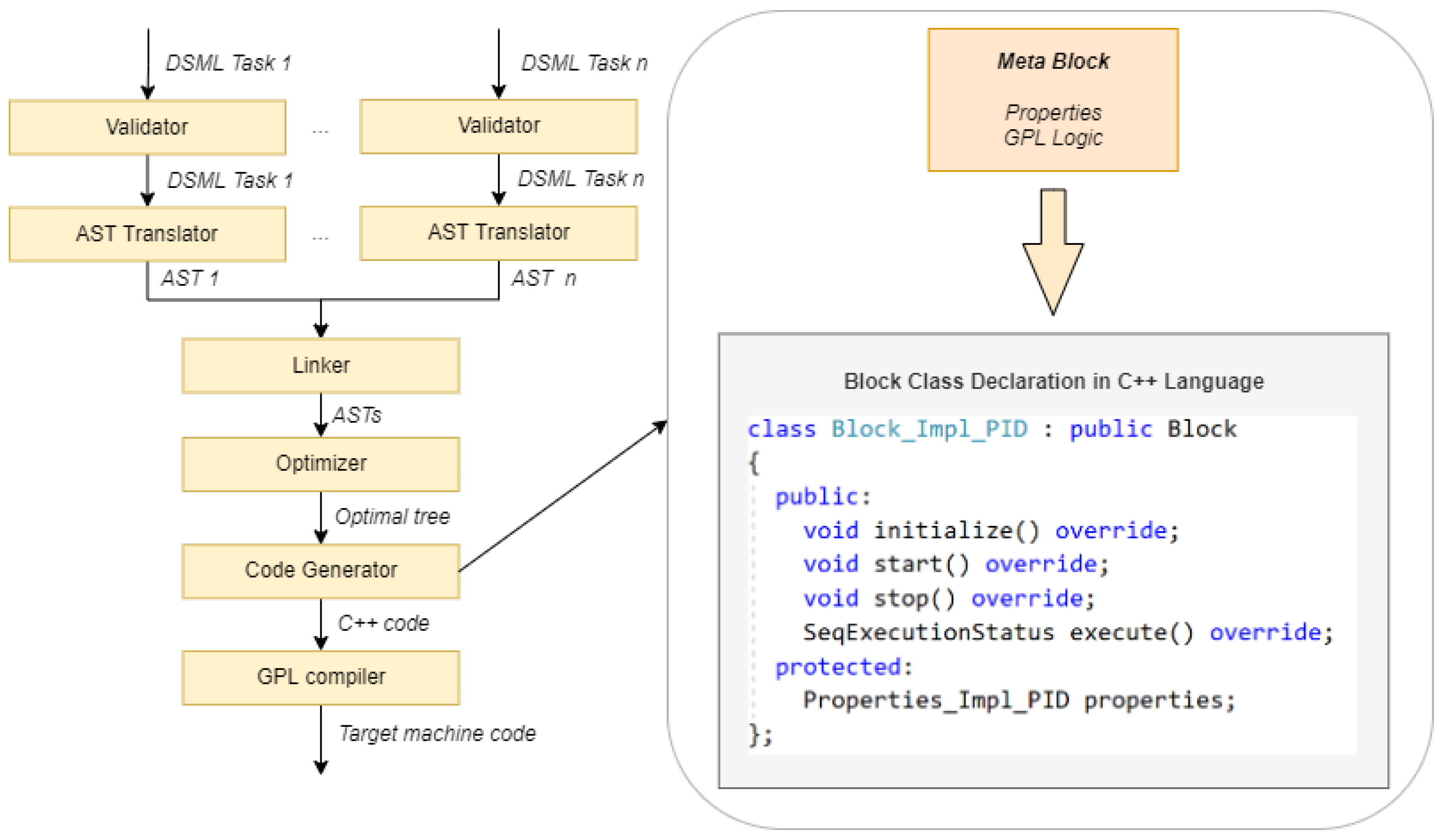
Besides the metamodel, we use additional rules and
validations (as shown in
Figure 7 on the left side) that we perform before translation. In our case, we divided the validation into two parts: warnings and errors. Warnings represent potential errors that can be checked before compiling, and can be critical while running the program. Examples of such warnings are, e.g., the incoherence of some visual blocks, which may represent unused visual blocks, or incorrect naming of variables. The second type of validation is errors that represent a semantic error in which further translation of the language is impossible. This type of error is, for example, the use of a non-existent variable or an undefined model or visual block.
After validating the model successfully, the next step is the translation into the AST of individual models with data and symbols. The sequence tree is built based on the model’s execution flow of individual tasks. Note that each task has its execution tree. Model variables are also evaluated in addition to tasks, models (a set of individual visual blocks) and visual blocks. Building an AST tree helps us later to connect and convert to other forms of notation (in our case, the C++ program code).
Once we have an individual AST tree for each task, we combine them in a linking process. In this process, we link different AST task trees and their dependencies. We determine the dependencies and relationships between local and global variables, visual blocks, and models. Following this procedure, we can do optimization easily and select which blocks are used. Only these used blocks will be translated into the generated C++ code.
The next step is
generating the C++ code from AST trees. On the right side of
Figure 7 we can observe an example of a visual block’s class declaration that is created automatically from the metablock (see the metamodel class
SeqGPLLogic description in the previous subsection, again). In addition to the basic inherited methods, the input and output variable properties are also created (attribute
properties).
When the entire C++ code is generated, it needs to be translated into the target machine code. We used the MinGW compiler to create an RTC program for a Windows host computer. In the case where it is intended to compile the RTC program on a remote system with the Linux platform, it is necessary to transfer the generated code to the RT controller, where the gcc compiler is installed. Through remote access, the RTC program is translated according to the required operating system and architectural platform. After successful translation, the RTC program can be run within the system environment.
6.3. Modeling Tool
We have divided the discussion on the modeling tool according to the domain expert and the advanced end-user perspective in RT-Sequencer.
6.3.1. Advanced Modeling Perspective
If there is a need for new visual blocks, it is necessary to use a tool to create new blocks and define logic with the GPL language. The advanced end-user can change the execution code or its properties within the tool. The tool is divided into four groups of properties that together define a new visual block. In the first group, we can change the basic properties, such as name, author, date, version, and determine how many outbound links each visual block has. In the second group, we plan the visual block and determine its shape visually. The third group contains visual block properties (
Figure 8), where we determine each visual block’s properties. The domain expert provides these properties later during the modeling measurement sequence, and affects the operation of the visual block itself and the RTC program as a whole. The fourth and final group contains the visual block execution logic itself or its execution code. As stated earlier in this paper, this tool is intended for advanced domain experts with C++ programming language knowledge.
6.3.2. Modeling Perspective
Domain experts can use three basic functionalities within the tool:
The first part of the environment is the system configurator, where we set different individual system components visually. Within this tool, we determine the tasks that are subsequently modeled, create the variables used (
Figure 9), and the general settings of the sequence.
The modeling tool is intended for creating the model, a workflow of the measurement sequence. The domain expert creates a model (procedure) with visual blocks. There is a working panel where we put the visual blocks and build the model. As in the previous version, basic modeling actions have also been added (zoom in/out, copy, paste, etc). For each visual block, we can change its properties. Once the model is prepared, it can be translated into executable code as described in
Section 6.2.
In the prepared model, the modeling tool also enables the processing and visualization of status channels within the RT control system. These statuses are variables defined within the tool, or pre-prepared statuses that communicate with the system and provide information about the proper functioning (CPU usage, memory, run-time timing, current run-time, etc.).
6.4. Execution Framework
The RTC program is executed in the controller within the scan cycle in four repeating phases (
Figure 10): reading inputs, executing program code, writing to outputs and communication, and system diagnostics. Reading inputs represents continuous monitoring of the status of the input modules. These modules can be digital inputs, analog inputs, and communication or special function modules (e.g., timers). Based on the input states and a program written by the domain expert, it makes decisions and manages the operation of output devices that communicate directly and control the output peripherals.
The RTC program is performed in an execution framework. The framework consists of the individual parts presented in
Figure 11. The gray-colored classes represent predefined execution tool objects, and the orange-colored objects represent generated classes based on a model written with a DSML. The
RT-Sequencer class includes the
ExeFramework class, where the program execution logic is executed. It forms the basis of the implementation program. Several programs or sequences (
Sequencer class) can be run inside. Sequences can have individual variables (
Variable class) and include different tasks (
Task class). Within the execution framework, tasks can be executed in parallel on different processes (
Process class). Individual models (
Class class) and, later, also visual blocks (
Block class), are executed on various processes. Models represent a set of individual visual blocks that can be executed sequentially, one after the other, or in parallel. The visual block contains the
Properties class and input/output variables (
Variables class). The
SeqInterface class is used to read and write the system’s input/output inputs, configuration, and communication, where there is a link between the platform and individual visual blocks.
The GPL logic of each meta block is generated into Block_Impl_N classes, and represents an extension of our program. In addition to logic, certain variables (Properties_Impl_N classes) are also created and accessible within the individual generated visual blocks. The program’s execution flow is defined in Task_impl_N classes.
7. A Demonstration of Extending Domain-Specific Modeling Language
Data acquisition and RTC systems often require complex hardware settings with various measurement devices, circuits, interfaces, etc. These must all work together within a variety of conditions. Testing products with a measuring device can cost a lot of money, especially if long preparations are required (ESA’s Ariane 6 rocket engine test,
https://dewesoft.com/case-studies/dewesoft-on-european-test-bench-for-large-launcher-solid-propellant-boosters (accessed on 12 October 2022)). For some tests, there is no possibility of repeating. Others take a very long time (Hong Kong—Zhuhai—Macao bridge monitoring,
https://dewesoft.com/case-studies/distributed-monitoring-on-world-longest-hong-kong-zhuhai-macao-bridge (accessed on 12 October 2022)). Therefore, measurement systems must be of high quality, and need to be tested to perfection. The smallest possible error factor should be reduced. For this purpose, many customers use simulators before a real test. Some also use reference devices to test the basic functionalities of the measurement devices before conducting important tests. Simulators generate various signals to validate the measurement system. Each simulator is built from the hardware, as well as from the RTC software. In the case of Dewesoft, the RT program that runs on the simulator is defined with RT-Sequencer. To demonstrate work with RT-Sequencer, we will show a model that will run on the simulator. In this way, we will describe the operations and functions necessary for validating the measurement system.
The validation system consists of a measuring part, a simulator, and a computer for management and control, as shown in
Figure 12. For example, we will test the functionality of the measuring device
Sirius XHS, a high-speed data acquisition system that can capture analog and digital inputs, CAN input, and different types of Ethernet interface data. This interface serves data to the
host computer. Moreover, the device has a synchronization port that can synchronize and connect different devices into a whole system. On the left side of
Figure 12 is a
simulator, that is intended to validate the measurement system before an important mission to verify different measurement systems’ behavior. Signals from the data acquisition device are connected (analog and digital signals, CAN, and synchronization). The simulator takes care of generating signals, CAN messages, and synchronization signals. Both devices are connected to the host computer, which takes care of data processing, validation, and programming of the simulator device within the DSML language. The Dewesoft X and RT-Sequencer modeling tool are installed on the host computer.
Now that the configuration of the measurement system is described, we present the software part of the validation, which will be divided into advanced end-user and domain expert perspectives in RT-Sequencer. We will show how a new set of constructs can be defined in RT-Sequencer, access the lowest API libraries, and optimize the code. Afterwards, we will present the domain expert perspective, describing the models created within the RT-Sequencer.
7.1. Advanced End-User Perspective
As stated, we will program the simulator with the RT-Sequencer. The simulator is controlled by a host computer and can generate various signals. To check the analog and digital inputs, the domain expert can generate different signals optionally that can be modeled within the RT-Sequencer. Signals are generated to simulate existing systems’ values as closely as possible. In addition, the device must also enable the generation of different CAN messages, which are also decoded at the domain expert’s request, so that we can simulate different engine control units (ECUs) of the device on the other side. Moreover, two protocols can be used for time correlation between individual devices. Via a precision time protocol (PTP) or inter-range instrumentation group timecode (IRIG timecode), we can ensure time synchronization according to absolute time.
As already mentioned, the simulator is intended to test various scenarios that are adapted to a specific domain and serve as validation of measuring devices before a real test. To make this possible, the domain expert needs a set of new visual blocks inside the RT-Sequencer. With them, we can create a sub-domain to determine the measurement procedures for the specific testing with the simulator.
Besides new domain constructs, there are predefined constructs in the RT-Sequencer. We can separate them into two categories: general-purpose constructs (supporting decisions, repetition, calculations, etc.) and measurement-specific constructs (delay, wait, etc.). These constructs were already present in the previous language Sequencer. These constructs remain unchanged, which enables easier adoption by prior domain experts. Note that some constructs were not included in RT-Sequencer from Sequencer (e.g., Action, File manager, Audio Video, and Macro block). Those visual blocks can be defined with the new language RT-Sequencer, but, in the specific case of testing with the simulator, these constructs are unnecessary, because the simulator does not need to perform actions on the Dewesoft X platform, visualize any data, etc.
Besides the predefined, some new constructs inside RT-Sequencer are needed to model the above requirements. Newly created visual blocks (
Table 1) enable modeling the simulator to generate different signals for testing purposes. We divided the visual blocks to four groups:
Analog signal,
Digital signal,
CAN and
Synchronization protocols (see
Table 1).
We defined each of these visual blocks from
Table 1 within the user’s block creation editor. The
Send CAN message visual block has been defined as shown in
Figure 13. We specified two output connections for the visual block. The first output connection link means the message was sent correctly, and the second means an error occurred. Then, the visual shape of the block was defined (rectangle). Visual block properties were also determined (see
Figure 8 again). These properties are the
PortNumber, which determines the sequence of the CAN device, since the device can contain more than one physical CAN port, the
Arbitration ID as the message identifier, the
message format, which can be of different types (binary, decimal or hexadecimal format),
message value and
message length.
When the visual block is defined the programming of the logic and behavior of the block follows within the GPL language (in our case, C++). The written code is divided into four predefined methods (
initialize,
start,
stop, and
execute), as shown in the program of
Figure 14. The first three methods are empty, since we do not need any functionality for this block. On the contrary, the method
execute has the functionality. First, we prepare the message according to
id,
format,
value, and
length (lines 23–26). After that, the message is sent to the physical bus (line 28), and, depending on the result, sets the output connection (lines 29 and 31). In this case, we have access to lower-level API libraries specific to a particular platform (in our case, the CANSocket library).
7.2. Domain Expert Perspective
When all the hardware and new visual blocks in the RT-Sequencer are prepared, the domain expert can start by creating a model for the simulator. The process begins with the modeling of different tasks that run in parallel. In our use-case, we have defined the following tasks:
Synchronization,
CAN,
Analog output, and
Digital output. Each of these tasks runs independently. In addition to the aforementioned new tasks, there are also predefined tasks. The
Error detection task ensures that if something unpredicted happens it shuts down the measurement system gradually. Besides,
Ethernet communication and the
Main program task (in
Figure 15) are also predefined tasks. In addition to tasks, it is necessary to add the local and global variables used in the model. After that, the domain expert has to define a model for each task separately. The domain expert focuses only on the simulator scenario. The model for the
CAN task is shown in
Figure 15. Here, the visual blocks are executed one after another (as shown by the arrow). The CAN port is initialized at the beginning (visual block
Initialize CAN), then the loop follows (visual block
Repetition). A CAN message is sent inside the loop. Upon successful sending, the message is incremented, and upon failure, an error is processed where the system stops in the correct order. On the right side of the tool, we can see the properties of the visual block
Send CAN msg), where various parameters can be set that we defined when the block was created.
In
Figure 15 we can see that, although the advanced end-user prepared the constructs within the GPL language beforehand, the model for the domain expert itself is still domain-specific and understandable to the measurement engineers.
When the whole sequence is defined and saved, the models are translated to C++ sources. Later, the source code is sent and built on the simulator. If there are no building errors, the module is loaded and run in RT mode. If we notice performance problems, we can optimize the algorithm in the model defined in the RT-Sequencer. Otherwise, we can start optimizing each visual block logic within the GPL language.
8. Related Work
Several aspects of the RT-Sequencer not discussed earlier in this paper are highlighted over the related work in this section.
Multi-level modeling [
36,
37] is an approach to conceptual modeling with multi-level DSMLs and multi-level modeling in general. This idea is based on several hierarchical levels, where an individual modeling environment on a specific level is created according to the sequence of previous (meta) models. Frank [
36] presents the general idea of the concept, requirements, and challenges related to multi-level modeling nicely, and finally presents the architecture that facilitates multi-level modeling on the example of information system design. Frank [
36] defines a proposition, that also holds for RT-Sequencer, that every concept on level
i should already be specified on level
i + 1. That must be true for each level of multi-level modeling if we want to minimize conceptual redundancy across all levels of abstraction. Our RT-Sequencer can be observed as an example of multi-level modeling with a metamodel and two DSMLs, one for advanced end-users and the other for domain experts. Note that our metamodel was created without any specialized metamodeling tool (e.g., MetaEdit+ [
16], GME (Generic Modeling Environment) [
9], EMF (Eclipse Modeling Framework) [
41]). On the other hand, we followed advice from Frank, e.g., RT-Sequencer is flexible to support an arbitrary number of multi-level levels (e.g., unit testing models).
Metamodeling in DSMLs and advanced end-user modeling in RT-Sequencer have a lot in common. Metamodeling defines the visual notation and behavior of a new DSML, and so does the advanced end-user modeling in RT-Sequencer. Therefore, we can claim that an advanced end-user performs typical language engineer tasks. The difference with metamodeling environments is that most of the RT-Sequencer visual blocks, notation, and logic are already fixed or predefined in the RT-Sequencer. Advanced end-user modeling does not affect the notation or behavior of the predefined constructs of the RT-Sequencer. Newly defined visual blocks have to follow the application programming interface provided by RT-Sequencer, and are therefore limited in many ways. On the other hand, this enables us to generate valid RTC programs. The RT-Sequencer could be implemented with a composition of metamodels [
42,
43], between predefined and newly defined constructs by an advanced end-user in RT-Sequencer. As an issue here, we can outline mappings between metamodel elements and execution semantics of the resulting unified modeling language. Therefore, we decided on another way, as described in this paper. As stated [
44], metamodels evolve frequently, and, as a result, we have a lot of models that do not match metamodels anymore. RT-Sequencer is a self-extensive language, where the metamodel consists of fixed elements less prone to evolve. Nevertheless, language evolution is natural, and we are aware of the importance of semi-automatic support for co-evolved models [
44], which is one of our future development orientations.
RT-Sequencer is also an example of collaborative language engineering [
45], although this has not yet been discussed in this paper. Advanced end-users cannot prepare visual blocks, logic, and behavior within GPL language without communicating and aligning with the domain experts. The RT control system is a mutual effort by both end-users. Izquierdo et al. [
45] present a concept of collaborative language engineering with an example-driven approach to the construction of DSML, where a metamodel is constructed automatically on the bases of model sketches, further resulting in the generation of a whole modeling environment. This process of collaborative development of DSML [
45] is related to the process in RT-Sequencer. The crucial differences are that the metamodel does not change in RT-Sequencer, since RT-Sequencer has capabilities to extend itself and enable new concept definition. Besides, in RT-Sequencer, the definition of the construct’s semantics is undefined and based on the GPL code provided by advanced end-users. Our collaboration process is yet to be studied. It can be one of our future directions, where domain experts engage and play an active role in language development in RT-Sequencer.
Literature review studies are an essential source of knowledge, and many also exist for the DSLs as well [
28,
30,
46]. A survey paper [
46] discussed what features practitioners expect from meta-modeling tools. The participants in the survey preferred to use DSMLs with diagrammatic notation with model-to-text transformations, whilst modeling editors should enable the reuse of the existing models stored in a repository. Moreover, a modeling editor should support an error marker to highlight the semantic errors at modeling time, and detect errors that may occur during the code generation process. The practitioners want syntax and semantic validation rules regarding language validation. Regarding language composability, the most crucial aspect is to reuse existing language semantics. Our meta-modeling tool indeed possesses all the required features. On the other hand, a survey [
30] concentrates on end-user involvement during the design, development, and evaluation of DSLs, and their impact on the DSL life cycle. From the point of view of end-user involvement in RT-Sequencer development, this study is also interesting for us to compare our development with practices reported in the study [
30]. Borum and Seidl [
30] provides six recommendations for DSL development. We can confirm that these recommendations regarding end-user involvement are adequate (e.g., expert evaluation for DSL evaluation, flexibility in the development process, the need for tool support, etc).
In [
47], the authors applied Model-Driven Engineering (MDE) for TinyOS applications where low-power wireless devices were used forming Wireless Sensors Networks (WSNs). In such an environment, the developers need to have deep knowledge of nesC, an extension of the C programming language for TinyOS. The authors pay special attention to how manually written code in nesC can synchronize with programs/models written in DSML4TinyOS [
47]. Namely, after the code modifications are performed in nesC, related changes must be synchronized with programs/models; otherwise, models become inconsistent. For this purpose, they introduce a model-driven round-trip engineering methodology. RT-Sequencer uses a forward engineering process where the RT program is modeled, and the corresponding code is generated using the modeling tool. Changing the program code is unnecessary in our case, since the GPL code can be nested inside the model by creating new blocks. As a result, there is no need for reverse engineering in the RT-Sequencer.
The comparison in research literature brings valuable and essential insights. However, comparisons in industry settings are, in most cases, hard to achieve. Superficially, from a domain-expert point of view, we can compare RT-Sequencer with similar solutions, for instance, TwinCAT (
https://www.beckhoff.com/en-us/products/automation/twincat/ (accessed on 12 October 2022)). A TwinCAT is a well-known development environment usually used for instrument control and industrial automation. It offers the possibility to program runtime modules in C/C++ within MS Visual Studio. The development tool also supports graphical programming language based on IEC 61131-3 standard. The standard defines the structure of programs, variables and data types, standard functions, and function blocks. It defines four basic programming languages, such as the Instruction List (IL), Structured Text (ST), Ladder Diagram (LD), and Function Block Diagram (FBD). An additional fifth, designed to structure tasks and program modules, is the Sequential Function Chart (SFC). Because these languages are standard, it is difficult to adapt them to a more user-friendly view and to support some features related to system programming. It cannot add new constructs, such as interfaces to new physical data buses, etc. If we compare the tool with RT-Sequencer, high-level DSML language and GPL language can be combined within RT-Sequencer with the possibility of domain specialization and manual code optimization. Another significant difference is that TwinCAT cannot merge the application areas of measurement and control or automation. In contrast, the RT-Sequencer and Dewesoft system supports both data acquisition and control.
9. Conclusions
In this paper, we presented RT-Sequencer, a successor of a DSML Sequencer [
24]. The development has been driven by the inclusion of new problem domain RTC systems combined with the original problem domain, data acquisition. RT-Sequencer differentiates two types of end-users: domain experts and advanced end-users. Considering these two facts, we decided on some requirements for the RT-Sequencer. For domain experts, these requirements are:
Modeling remains in the hands of domain experts,
New visual blocks to support the modeling of RTC systems,
No GPL programming knowledge is needed to create procedures with the RT-Sequencer,
Models for the same measurement sequence are equivalent in Sequencer and the new language RT-Sequencer,
The complexity of the models must be kept at the same level as in the previous language Sequencer, and
productivity using RT-Sequencer needs to be improved compared to PLC programming.
For advanced end-users, we defined the following requirements for the RT-Sequencer:
Flexible language that can define new constructs,
Extends the DSML language with a new GPL construct,
The ability to optimize the performance of some part of the sequences, and
The ability to define language constructs that support single or both problem domains.
The DSML RT-Sequencer is implemented within the software package DEWESoft. Before, end-users of this software package could use only the predefined Sequencer’s visual blocks. In this paper, we present a new DSML where advanced end-users can define new constructs of a language. The meaning of those new constructs of a DSML is defined with C++ code, which is used further to define the modeling environment and measurement procedure definition of the RTC system. In this manner, our DSML can be observed as multi-level modeling with two different end-user roles. With this architecture, the metamodel of RT-Dewesoft can stay the same, no matter what new functionalities we need for the RTC system. However, as one limitation, we can outline that advanced end-users are limited to the API predefined for extending a modeling language, which is a potential point for future extensions.
Similar to other software solutions, DSMLs evolve. Usually, after their first use, new ideas emerge, such as language constructs, further implications of usage, application domains, corrections of the development process, etc. In the study [
30], it is reported that the DSL end-of-life is usually, among other reasons, due to changes in the domain that were not addressed promptly, better tooling desired by end-users, etc. Finally, this can result in the adaption of another solution. It is crucial to evolve the DSML [
30] to prevent such a scenario. We confirm that extensions are one of the key factors to the success story of our DSML. As shown in paper [
27], several extensions provided domain experts with new language features and tooling, even with supporting another domain. Experiences with the evolution of our DSML are one of the implications of this work for DSML researchers and practitioners from industry. Other benefits for the DSML community are specific decisions and implementation details that we have made during the development of RT-Sequencer.
RT-Sequencer is still a new language. We cannot report how much assistance the customers will need from Dewesoft’s language engineers to prepare sequences for RTC systems. Neither do we have information on whether customers have problems differentiating end-users roles inside RT-Sequencer. The cost of RT-Sequencer maintenance and support inside DEWESoft is yet to be observed. Besides, as one of the future directions, we foresee the evolution of models [
48] on an advanced end-users level, and how this affects already defined models by domain experts. Semi or fully-automated co-evolution tools are yet to be prepared to support these transformations.


