Article

Mutual Coupling Effect and Reduction Method with Modified Electromagnetic Band Gap in UWB MIMO Antenna

by
Gabriel A. Fadehan
,
Yekeen O. Olasoji
and
Kazeem B. Adedeji
*
Department of Electrical and Electronics Engineering, The Federal University of Technology, Akure P.M.B 704, Ondo State, Nigeria
*
Author to whom correspondence should be addressed.
Appl. Sci. 2022, 12(23), 12358; https://doi.org/10.3390/app122312358
Submission received: 31 October 2022 / Revised: 28 November 2022 / Accepted: 1 December 2022 / Published: 2 December 2022
(This article belongs to the Special Issue Recent Challenges and Solutions in Wireless Communication Engineering)

Abstract

:
In this paper, an effective technique for mutual coupling (MC) reduction between antenna elements of two multiple input multiple output (MIMO) microstrip patch antennas operating in the ultra-wide band (UWB) between 3.1 and 13.5 GHz is presented. The antenna array separation was kept at 44 mm for investigation, and the isolation was achieved through a modified electromagnetic band gap (MEBG) decoupling structure. The MEBG is embedded behind the radiating elements connected to the ground plane. HFSSv15 software was used to design and simulate the antenna. The effectiveness of the antenna and the MC reduction method was examined with and without the MEBG structure. The results revealed that the MC between the MIMO antenna elements was minimized when the MEBG structure was introduced. An MC of about −23 dB was obtained over the entire UWB frequency spectrum. This is more than a 10 dB improvement over the reference antenna (without the MEBG structure). Without limiting the effectiveness of the antenna when the MEBG structure was introduced, the results of the envelope correlation coefficient (ECC) gave the antenna a satisfactory diversity performance. The MEBG UWB MIMO antenna has an ECC less than 0.09 with a wide bandwidth. In addition, the total gain and the Voltage Standing Ware Ratio (VSWR) results were analyzed, which show that the performance of the antenna was not degraded while reducing the MC effect between the MIMO antenna elements.

1. Introduction

The Federal Communication Commission (FCC) announced in 2002 that frequency spectrum from 3.1 to 10.6 GHz would be made available for UWB applications, ushering in a new era of low-powered, high-data-rate communication that is more pronounced in compact and hand-held systems [1]. The advantages of the UWB system include a low power consumption and high resistance to interference from its narrow band counterpart [2,3,4]. One significant factor that affects the efficiency and reliability of UWB communication systems is multipath fading [5]. However, using antenna arrays assisted by MIMO technology is one approach to addressing these issues and improving UWB system performance [6,7,8,9,10]. One of the key advantages of MIMO technology is the increase in channel capacity without the need for extra power or bandwidth [11,12]. However, there is a remarkable challenge to the MC effect between UWB antenna elements when confined within a small available space [6]. Antenna MC is a term used to describe the energy absorbed by an adjacent antenna using the same frequency. When the antenna elements are placed close to one another, there is a significant correlation between the signals radiated. Research studies [13,14,15] revealed that MC significantly affects the performance of antenna arrays. Therefore, in the design of UWB MIMO antennas, achieving an antenna with a relatively small structure and a low MC are the most critical factors that must be considered. To minimize the MC effect, isolation methods are applied among the antenna elements. Numerous isolation methods have been used to minimize MC among antenna arrays. Some of these include the embedding of EBG structures, defected ground structures (DGS), metal-surfaces, placing of metal strips between elements, and the use of orthogonal polarization and neutralization line techniques [16,17,18,19]. Several studies in this domain have been reported in the literature. To achieve multiple resonance and excellent isolation between the radiating elements of two monopole UWB MIMO antennas, an F-shape stub was employed in the ground plane in [20] and achieved a MC <−20 dB. In this study, a low MC with S12/21 < −20 dB was achieved. In [21], the effect of reducing the surface wave with an EBG structure and its use to minimize the MC was investigated. Applying a finite difference time domain (FDTD), its impact on an infinitesimal dipole source with and without the EBG structure was compared. While the FDTD method was established to examine the MC of the arrays of probe-fed patch antennas, EBG structures were also used to enhance antenna performance. The results indicate an MC of −24.6 dB. The studies in [22] are like those presented in [21], aside from the use of a uni-planar compact EBG (UC-EBG) inserted between antenna elements. A comparison between UC-EBG and without UC-EBG was made. Simulation results show a great reduction in the MC with a −19 dB difference. In [23], a comb-line structure that served as an EBG between the MIMO antennas to reduce the MC between the two antenna arrays was formed in the radiating element. A suppression of −24 dB covering the whole UWB bandwidth was achieved. In [24], a compact quad-band notched UWB-MIMO antenna with two symmetrically inserted L-shaped slots on each radiator and C-shaped stubs acting as a decoupling element was proposed. Within the UWB band of 3.1–10.6 GHz, a high isolation of less than −25 dB was obtained when the two elements were perpendicular to one another. The authors in [25] proposed a Pacman-structured MIMO antenna using two orthogonally positioned antenna elements operating between 2.9 GHz and 15 GHz. The simulation result shows that an isolation of less than −17 dB was achieved. Elsewhere [26], a miniaturized UWB MIMO antenna with a simple notched filter realized by a trident-shaped strip was utilized. The top layer consists of two 50 Ω lines, while the bottom layer is a ground plane with two stepped slots that form a T-shape. With the etched T-shape, an MC of less than −20 dB was obtained. In most of these studies, the other performance of the antenna was slightly affected. In [27], researchers use defected ground structures to reduce the MC between UWB MIMO antennas. The proposed structure only covers 3.0 to 10 GHz with an antenna size of 60 × 35 mm2. Similar to the studies in [27], a defected ground structure on a monopole antenna was loaded with U-stub for mutual coupling reduction in an UWM MIMO antenna as proposed by [28]. The frequency coverage was slightly increased from 3.18 to 11.50 GHz with an antenna size of 40 × 40 mm2 and an isolation of less than 18 dB. In [29], a good isolation >20 dB was achieved within a very low frequency between 3.34 to 3.87 GHz with an antenna size of 20 × 35 mm2. Studies in [30] utilizes a uniplanar EBG exhibiting multiple stop bands to achieve a MC of −18 dB within a large frequency band between 3.6 to 17.6 GHz but with large antenna size of 46 × 27.2 mm2. Prabhu and Malarvizhi [31] use a double-sided EBG for MC reduction among the quad port of UWB MIMO antenna to achieve an isolation <−20 dB and an antenna size of 30 × 30 mm2 within a 3–11 GHz frequency range. In [32], the proposed methods cover an extremely low frequency band between 2 to 7 Ghz to achieve 20 dB isolation with an antenna size of 49 × 26.2 mm2. More recently, Urimubenshi et al. [33] proposed a novel approach for low MC reduction for UWB wireless applications. In this study also, an isolation of −19 dB was achieved with an improved antenna size of 46 × 27.2 mm2 and was able to cover 4 to 12 GH. Considering these studies, we observed that an improved isolation for the full UWB range is not achieved. Aside from covering a small bandwidth, the antenna size becomes too large, which limits its use for handheld wireless applications. In this paper, a modified electromagnetic band gap was used as a decoupling structure between the radiating elements of a MIMO antenna operating within the UWB frequency band. The decoupling capability of the MEBG structure was examined and analyzed. In addition, the performance of the antenna was assessed when the MEBG was introduced and compared to the reference antenna without the MEBG decoupling structure. In view of this, the contribution of this paper is as follows.
  • We propose an improved mutual coupling reduction method that achieves a relatively high isolation of −23 dB that covers a broadband of frequencies.
  • The MC reduction method was designed in a way that we achieved a small antenna size 19 × 24 mm2 when compared to previous studies.
Unlike previous methods and studies used for MC reduction, the method introduced for MC reduction does not degrade the performance of the antenna. A modified EBG was employed in symmetrical order for mutual coupling reduction, unlike the other EBGs with mushroom patterns [21,22]. The remainder of the paper is structured as follows: Section 2 presents the process involved in the UWB patch antenna design; Section 3 presents the design of the UWB MIMO antenna and the performance evaluation metrics; Section 4 presents the results and discussions; Section 5 presents a comparative analysis of the performance of this method with previous related studies in the literature; Section 6 concludes the paper.

2. UWB Patch Antenna Design

2.1. Geometric Structure

Figure 1 illustrates the geometry of the rectangular patch antenna design. Typically, the feed lines and radiating elements are photoetched onto a dielectric substrate. The radiating patch, like the ones in [34,35], is square-shaped and mounted on an FR4 substrate with dimensions of 31 by 24 mm. The patch antenna was developed using a copper material with only a thickness of 0.038 mm on an FR4 substrate with a dielectric constant (ϵr) of 4.4. To establish a feed gap between the ground and the patch, a partial ground that was 12 mm long was used with the patch. The ground was then again downsized by 0.5 mm; this increased the bandwidth of the entire antenna. The radiating patch’s corners were beveled to increase its impedance bandwidth (s11< −10 dB) between 3.1 GHz and 14 GHz. To improve impedance matching over the full UWB range, a notch was etched into the partial ground plane just behind the transmission line. Further, a 50 Ω impedance with a 0.02 loss tangent was used to feed the micro-strip line.

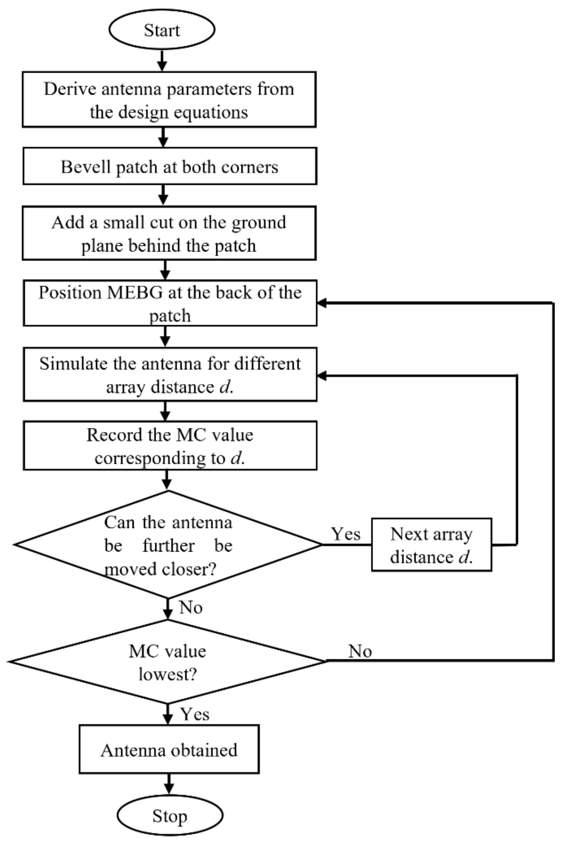
2.2. The Flow Chart of the Proposed Approach

Figure 2 shows the flow chart of the proposed mutual coupling reduction for the UWB MIMO antenna. Based on the geometrical structure in Figure 1, the antenna parameters are obtained using a set of design equations. Patches are beveled at both corners of the antenna to enhance the impedance bandwidth. In addition, a small cut is provided on the ground plane of the antenna behind the patch to achieve impedance matching. Thereafter, two MEBGs are placed at the back of the patch in symmetrical order to optimize the performance of the antenna. The antenna array elements are separated by a far-field distance d. The value of d was varied, and corresponding mutual coupling values were observed for each distance. The far-field distance is varied until a satisfactory (lowest) MC value was obtained.

2.3. Design Equations

Several generic equations are required to estimate the antenna parameters, which govern the antenna design process. For a given ϵr, Equation (1) expresses the effective dielectric constant.
ϵ e f = ϵ r + 1 2 + ϵ r 1 2 1 + 12 h W 1 / 2
In Equation (1), h and W represent the substrate’s height and width, respectively, while W h   1 represents the substrate’s width-to-height ratio for minimizing the fringing effect. The ϵef and W h are two important factors that affect the extended length ΔL of the patch. Equation (2) gives the normalized extended length of the patch.
Δ L h = 0.412 ϵ e f + 3 W h + 0.264 ϵ e f 0.258 W h + 0.8
The effective length for dominant mode without fringing effect is then given as
L e f = L + 2 Δ L
Equation (4) describes how the patch antenna’s resonant frequency fr depends on both its length L and the speed of light v.
f r = 1 2 L μ 0 ϵ 0 ϵ r = v 2 L ϵ r
In Equation (4), μ 0 denotes the permeability of free space, while ϵ 0 is its relative permittivity. To account for fringing in order to include edge effects, Equation (4) is modified as
f r f = 1 2 L e f μ 0 ϵ 0 ϵ e f = 1 2 L + Δ L μ 0 ϵ 0 ϵ e f f r f = q 1 2 L μ 0 ϵ 0 ϵ r = q v 2 L ϵ r
In Equation (5), frf is the resonant frequency due to fringing effect, while the factor f r f / f r denotes the fringe factor (length reduction factor). Both W and L are determined using Equations (6) and (7) [35].
W = 1 2 f r μ 0 ϵ 0 2 ϵ r + 1 = v 2 f r 2 ϵ r + 1
L = 1 2 f r ϵ e f 2 Δ L  
In these expressions, an increase in h causes an increase in fringing. This produces a significant separation between the radiating edges and the lower fr. Table 1 illustrates the dimensions and design parameters of the UWB patch antenna with the geometric configuration shown in Figure 1.

2.4. Introducing EBG Structure into the Patch Antenna

An EBG is established by placing a structure close to a patch to produce a field gap through the ground. The ground plane and the EBG structure are joined through a shorting pin called a via. It is a suitable option for creating low-profile, highly effective antennas [36]. An appropriate LC resonator can be used to represent a via-loaded metal patch connected to the ground. The parameters of the inductive (Lin) and capacitive (C) parts are described by Equations (8)–(10) [37].
L i n = 0.2 h ln 2 h r 0.75
C = ε 0   ε r w 2 h
w 0 = 1 L C
In Equations (8)–(10), ε0 and εr denote permittivity parameters, while h and r denote the via’s height and radius, respectively. Further, w and w0 are the EBG’s width and the resonant angular frequency, respectively. The EBG structure could be observed as a mushroom-swollen surface, studied in [36], and was enhanced to produce M-EBG (see Figure 2). Figure 3 gives the structure and dimensions of the M-EBG. The M-EBG is portable, simple, and capable of generating decoupling effect in any common UWB array antennas when positioned in the feed line vicinity of the UWB micro-strip antenna.

3. MIMO UWB Antenna

This section presents an analysis of the significance of the decoupling structure in reducing the MC in MIMO UWB antennas. The antenna design with and without the inclusion of the decoupling structure was discussed.

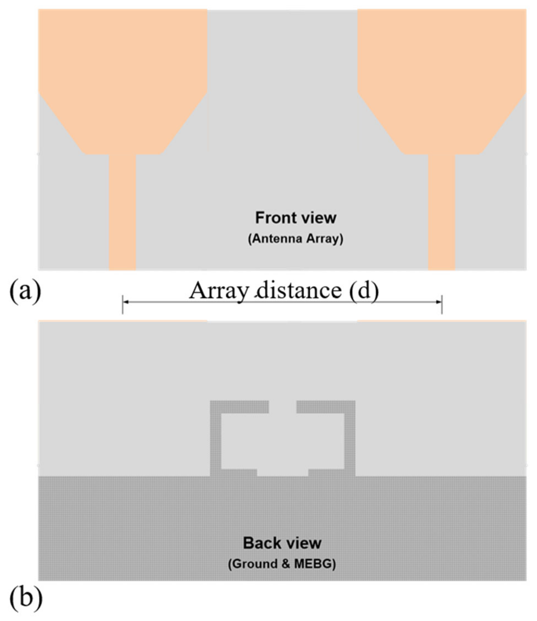
3.1. Antenna Array without MEBG

Figure 4 presents the layout of the UWB MIMO antenna created with HFSSv15 software. Two UWB monopole antenna elements were joined to form the antenna. The initial patch antenna structure’s dimensions were selected to achieve a resonance frequency of 6.85 GHz, which corresponds to the UWB’s center frequency. The maximum allowable distance d between the MIMO antenna elements could be derived from the far-field expressions illustrated in Equations (11) and (12).
v = f λ
d 2 D 2 λ
where f denotes the resonant frequency, λ is the wavelength, and D represents the antenna’s diagonal. At any distance above the far field, the MC in any MIMO antenna is at its minimum value. Due to the space constraints in UWB antenna design, the arrays are placed close together. Figure 5 illustrates the S-parameter of the MIMO antenna system without the MEBG decoupling structure. This demonstrates that for various values of distance d less than 2 D 2 λ far field, the MIMO antenna has an impedance bandwidth smaller than −10 dB within the UWB frequency band. At a far field distance equal to some certain fraction λ, the S-parameter (S11 and S12) without decoupling structure is presented in Figure 5. This figure shows the variability of the S-parameter with the far field distances. Table 2 supplements the figure by showing the average MC effect when the decoupling structure has not been introduced into the array. As shown in Table 3, an increase in far field distance drastically improves the MC. Of course, this indicates the effect of increasing the separation between the array elements. In a closely packed array, the MC effect is more pronounced.

3.2. Antenna Array with MEBG

To enhance the MC effect between the antenna array, a MEBG was used as a decoupling structure. Figure 6 presents the structural layout of the UWB MIMO antenna with the MEBG. The initial patch antenna structure’s dimensions were selected to achieve a resonance frequency of 6.85 GHz, corresponding to the UWB’s center frequency. A decoupling structure of a modified EBG was used between the two antennas, with each antenna having its MEBG behind the radiation element connected to the ground plane. In Figure 7, the variation of the S-parameter (S11 and S12) of the decoupling structure with various array distances d is presented, while Table 3 supplements the figure by showing the average MC effect when the MEBG decoupling structure was introduced into the array. As shown in Table 3, it was noticed that a better improvement in the MC is achieved as the far field distance increases in comparison to Table 2.
Table 3. Variation of the MC with the far field distance (mm) for the MIMO UWB antenna arrays when the MEBG decoupling structure is introduced.
Distance (d)LegendMutual Coupling (S12)
34Applsci 12 12358 i006−18.73
44Applsci 12 12358 i007−19.45
54Applsci 12 12358 i008−22.59
64Applsci 12 12358 i009−23.38
74Applsci 12 12358 i010−23.49
The performance of the antenna was examined using the S-parameter, surface current distribution, gain and voltage standing wave ratio (VSWR), radiation pattern, and ECC. The ECC can be estimated from the S-parameter using the expression given in Equation (13) [38].
ECC = S 11 * S 12 * + S 21 * S 22 * 2 ( 1 S 11 2 S 12 2 )   ( 1 S 22 2 S 21 2 )
where S11 denotes the power reflected from the input port of the antenna, S12 is the power transmitted from the output port, S21 is the power transmitted from the input port, and S22 denotes the power reflected from the output port. To assess the impact of the decoupling method on the performance of the antenna, an analysis was also carried out for the antenna before the MEBG decoupling structure was introduced. The antenna design was carried out using HFSS modeling tools on a dual-core computing system.

4. Results and Discussions

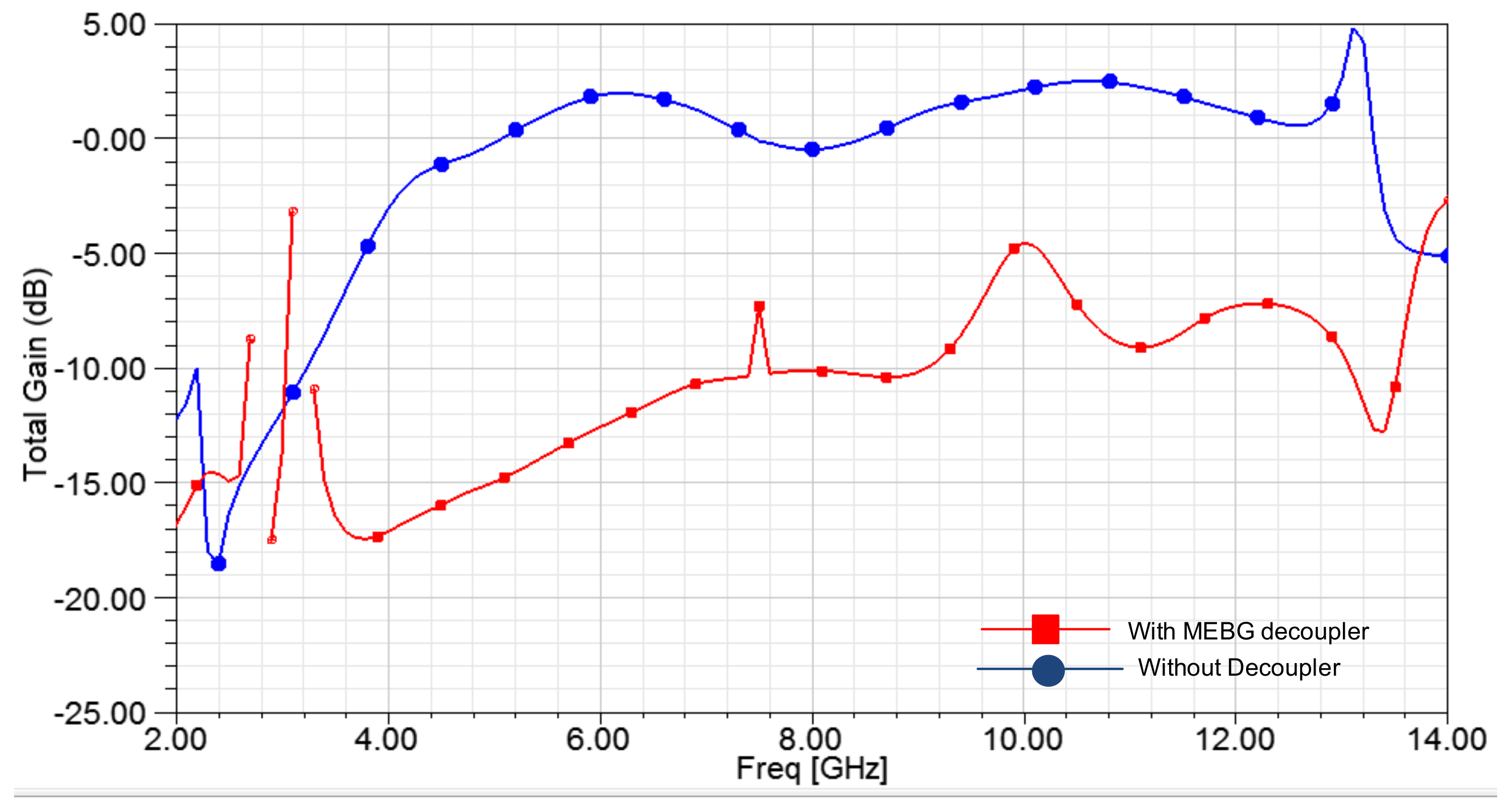
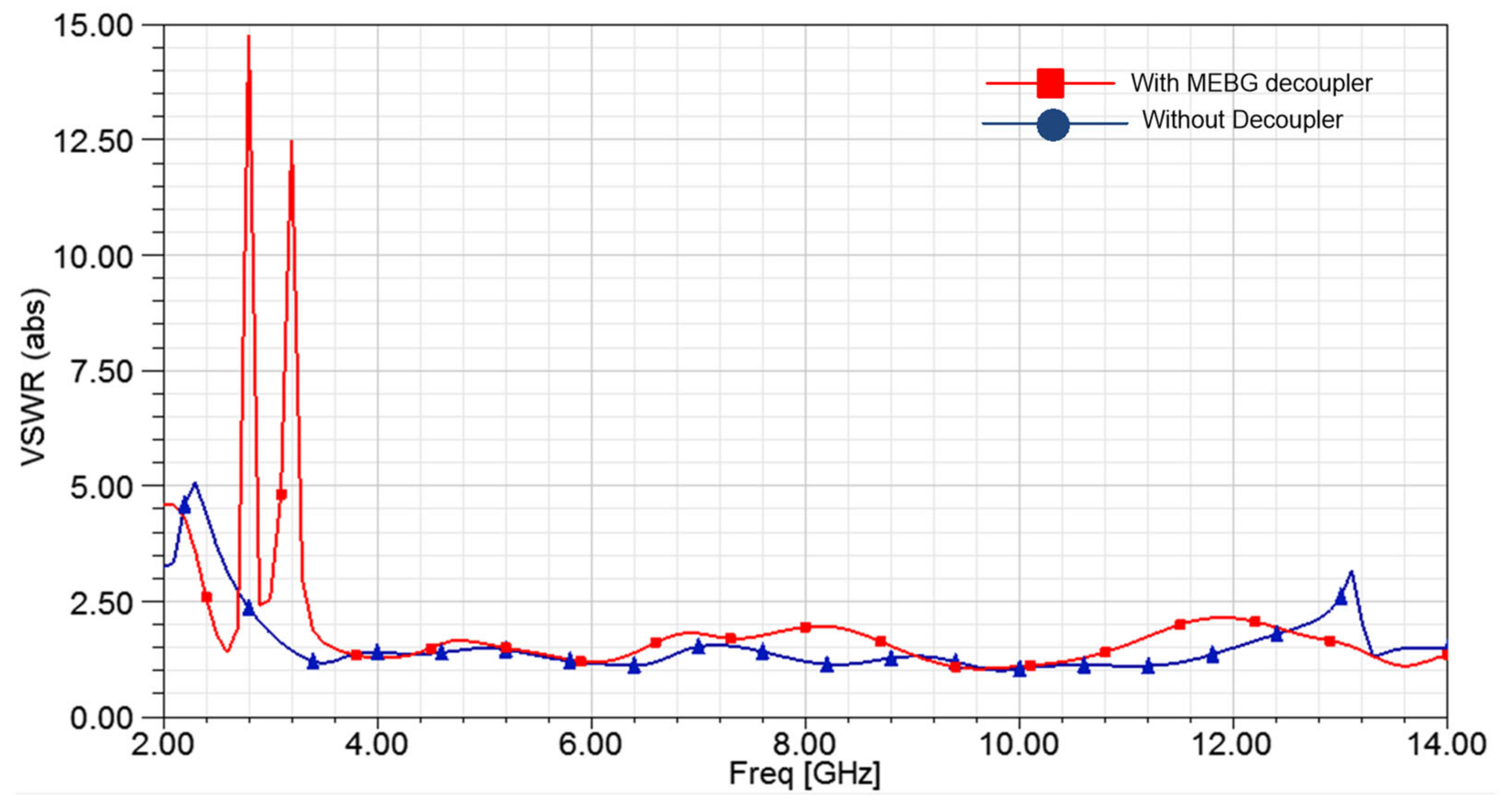
4.1. Antenna Gain and VSWR

Figure 8 shows the array gain at a 44 mm far-field distance with and without the decoupling structure. When compared to an array without a decoupling structure, the MIMO antenna’s average gain has increased by 12 dB as a result of the MIMO structure and the decoupling structure. In Figure 9, the VSWR of the antenna with and without MEBG structure is presented. As can be observed, the VSWR is less than 2.0 within the frequency band for both scenarios. This indicates that there has not been a major change in the VSWR of the antenna since the decoupling structure was introduced, and thus the performance is not degraded.

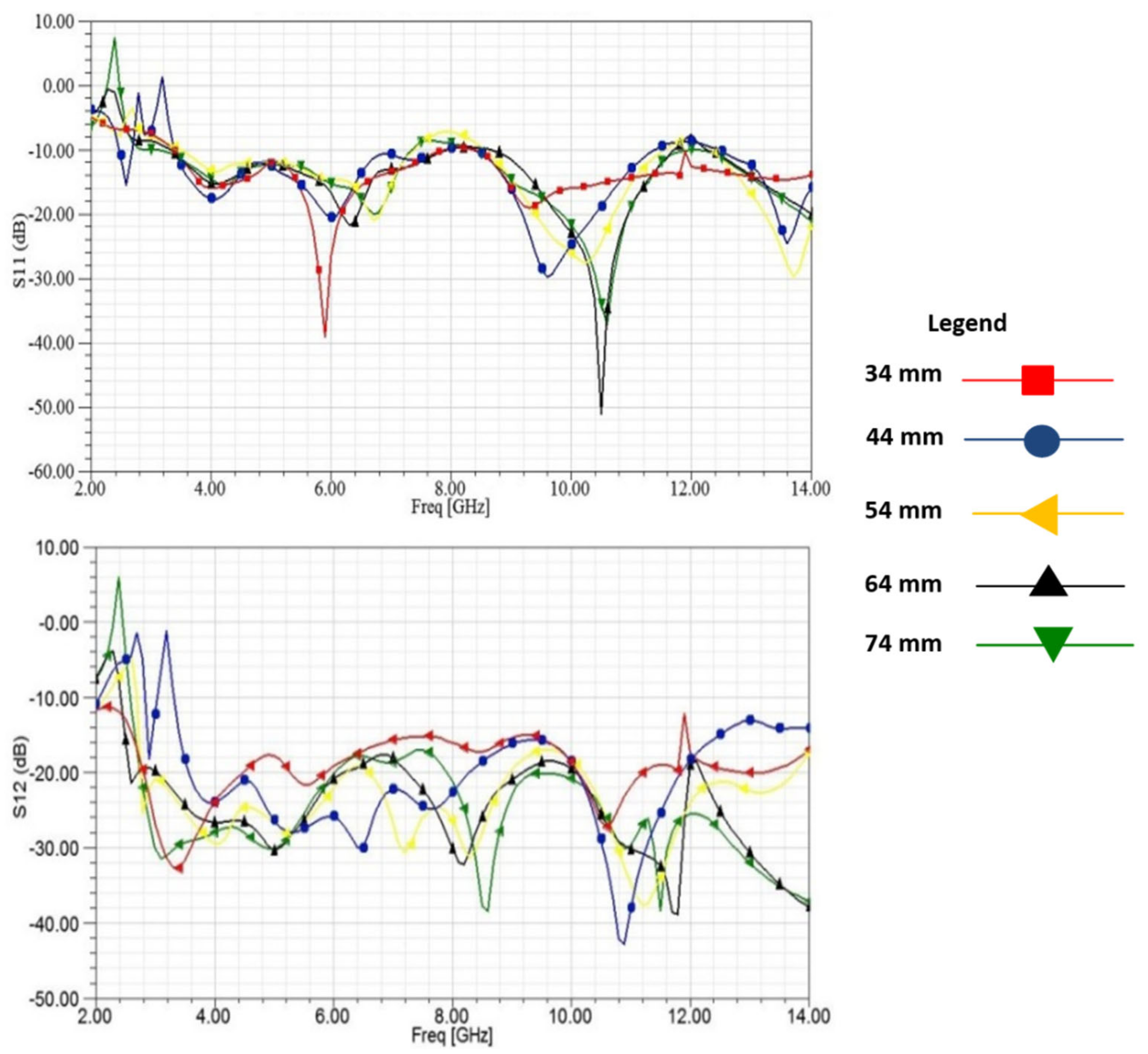
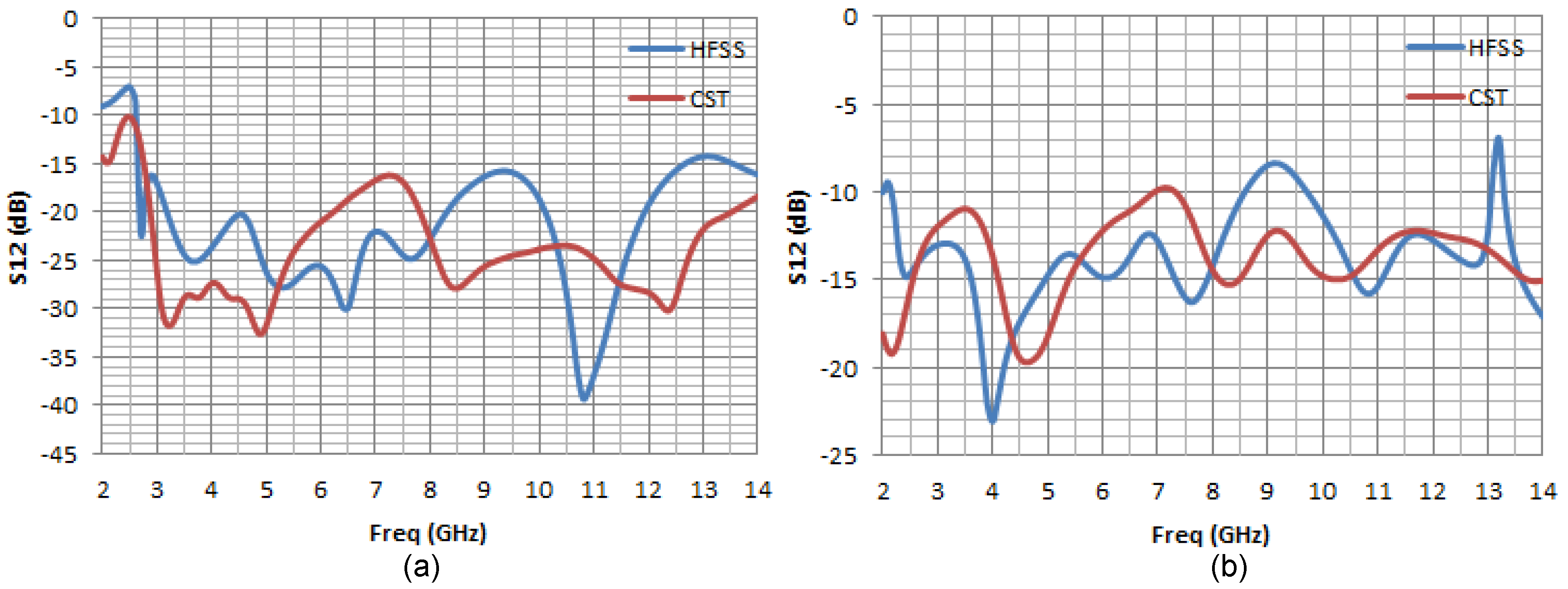
4.2. The S-Parameter

Figure 10 presents the S-parameter of the UWB MIMO antenna at a separation distance of 44 mm. The S11 (Figure 10a) and the S12 (Figure 10b) parameters were presented with and without MBEG structure. The overall average isolation without decoupling is −13 dB. However, the MC effect was improved by the addition of the decoupling structure. With introduction of the MBEG structure, the MC between the arrays is improved to about −23 dB in the large portion of the UWB band. This is around a 10 dB improvement over the reference antenna (antenna without the decoupling structure).

4.3. Current Distribution

The surface current distribution with and without the inclusion of the decoupling structure is depicted in Figure 11. The current distribution between the array elements when one antenna is energized, and the other antenna is terminated by matching impedance was examined for both situations. From Figure 11a, a strong coupling could be observed between the arrays on the common ground plane that propagates to the non-energized antenna 2 on the right-hand side. The surface current density (J−surface) in antenna 2 revealed the undesirable coupling induced by excited antenna 1. To illustrate the effects of the MEBG structure, the antenna was then simulated at the same frequency of 6.85 GHz (Figure 11b). With the MEBG decoupling, it is evident that very little surface current density is flowing towards antenna 2. The MEBG has successfully prevented a substantial portion of the current that would otherwise propagate undesirably to antenna 2. MEBG, therefore, could considerably improve the isolation of MIMO antenna systems.

4.4. Radiation Pattern

Figure 12 presents the E-field and H-field patterns of the UWB antenna array obtained at 4.5, 6.85, 7.5, 8.5, and 9.5 GHz, respectively. At lower frequencies, the E-field pattern with MC structure has 8-shape patterns with little variation at the higher frequencies. The E-field pattern without the decoupling structure does not have a regular shape. Looking at the H-field pattern, with the introduction of the MBEG decoupling structure, an omni-directional shape is observed for all the frequencies considered. A different pattern is observed when the decoupling structure was not introduced. At lower frequencies, the H-field tends to a point and exhibits an “8” shape only at 8.5 GHz.

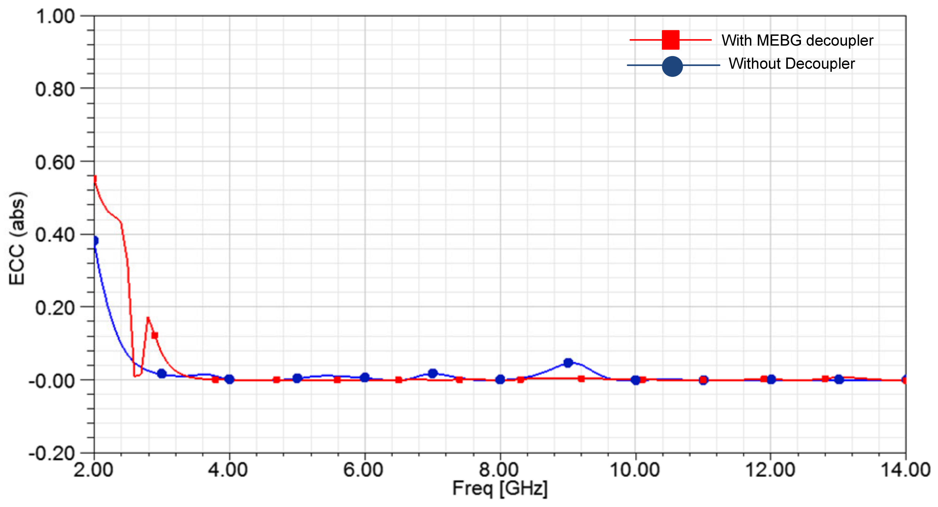
4.5. Diversity Performance

The diversity performance is based on the ECC. The ECC performance of the antenna with and without the decoupling structure is shown in Figure 13. With the MEBG structure, the antenna has an ECC value of less than 0.09 for the UWB frequency between 3.1 and 13.5 GHz. Without the decoupling structure, a spike above the 0.09 ECC value was observed between these frequencies. For instance, a significant difference can be observed at 7 GHz and 9 GHz where the ECC has a value above 0.09. This shows that with the introduction of the MEBG structure, the effectiveness of the antenna was not degraded. This makes the antenna a good candidate for MIMO communication systems.

4.6. Result Validation

The results presented in this study were validated using CST software. In this section, we present the comparison of some of the results obtained from HFSS with those obtained from the CST software when plotted together in Microsoft Excel. While the operating band of UWB under this study is 3.1 GHz to 10.6 GHz, the graphs plotted show a frequency range from 2 GHz to 14 GHz only to observe what happens outside the UWB band and is not relevant to the present study. Figure 14 and Figure 15 show the S-parameters (S11 and S12) of the MIMO-UWB antenna with and without the MEBG decoupling structure for both HFSS and CST software. From these figures, it can be observed that the results presented by HFSS are not out of range when the antenna is validated using CST software. The MIMO-UWB antenna with and without the MEBG structure designed for the HFSS platform gave a similar response to that of the CST simulation software within the UWB band of 3.1 GHz to 10.6 GHz.

5. Comparative Analysis

In Table 4, the results of the current study are compared with those of the previous studies [39,40,41,42,43,44,45,46] in the literature based on the antenna type and decoupling structure used, the operating frequency, and the MC value. The results demonstrate that the current study was able to achieve a relatively improved MC reduction over a wide range of frequencies. It should be noted that the research studies in [39,43] also achieve similar results and a relatively higher reduction in MC for [43], but within a narrow band of frequencies (3.1–11 GHz for studies in [43]).

6. Conclusions

In this paper, a modified electromagnetic band gap for suppressing the MC between two rectangular patch UWB MIMO antennas is presented. The proposed MEBG was applied to minimize the MC between two adjacent MIMO antenna arrays. The antennas are kept apart at a distance of 44 mm. Two MEBGs were applied symmetrically behind the antenna and a relatively high isolation around −23 dB (more than a 10 dB improvement over the reference antenna) was achieved across the whole operating bandwidth of the MIMO UWB antenna. The antenna performance with and without the MEBG decoupling structure was also examined. Simulation results of reflection coefficient S11, mutual coupling, radiation features, and diversity performance based on the ECC were equally examined. The MEBG structure introduced significantly reduces the MC effect without degrading the antenna performance. With the introduction of the MEBG decoupling structure, a comparatively low ECC value less than 0.09 was achieved with a wide bandwidth. The antenna results were verified in CST simulation tools and the results are similar to HFSSS simulation within the UWB bandwidth. The results show that the antenna exhibits better diversity performance and is a good choice for UWB applications.

Author Contributions

G.A.F. conceived the original idea of the paper and was in charge of the manuscript draft while Y.O.O. and K.B.A. helped with some improvements in the paper. All authors have read and agreed to the published version of the manuscript.

Funding

This research received no external funding.

Institutional Review Board Statement

Not applicable.

Informed Consent Statement

Not applicable.

Data Availability Statement

Not applicable.

Conflicts of Interest

The authors declare no conflict of interest.

References

  1. Saxena, S.; Kanaujia, B.K.; Dwari, S.; Kumar, S.; Tiwari, R. A compact dual-polarized MIMO antenna with distinct diversity performance for UWB applications. IEEE Antennas Wirel. Propag. Lett. 2017, 16, 3096–3099. [Google Scholar] [CrossRef]
  2. Wang, D.; Yoo, S.; Cho, S.H. Experimental comparison of IR-UWB radar and FMCW radar for vital signs. Sensors 2020, 20, 6695. [Google Scholar] [CrossRef] [PubMed]
  3. Zhang, X.; Yang, X.; Ding, Y.; Wang, Y.; Zhou, J.; Zhang, L. Contactless simultaneous breathing and heart rate detections in physical activity using IR-UWB radars. Sensors 2021, 21, 5503. [Google Scholar] [CrossRef] [PubMed]
  4. Abbas, A.; Hussain, N.; Lee, J.; Park, S.G.; Kim, N. Triple rectangular notch UWB antenna using EBG and SRR. IEEE Access 2020, 9, 2508–2515. [Google Scholar] [CrossRef]
  5. Li, J.F.; Chu, Q.X.; Li, Z.H.; Xia, X.X. Compact dual band-notched UWB MIMO antenna with high isolation. IEEE Trans. Antennas Propag. 2013, 61, 4759–4766. [Google Scholar] [CrossRef]
  6. Mchbal, A.; Touhami, N.A.; Elftouh, H.; Dkiouak, A. Mutual coupling reduction using a protruded ground branch structure in a compact UWB owl-shaped MIMO antenna. Int. J. Antennas Propag. 2018, 2018, 4598527. [Google Scholar] [CrossRef] [Green Version]
  7. Abd El-Hameed, A.S.; Wahab, M.G.; Elshafey, N.A.; Elpeltagy, M.S. Quad-port UWB MIMO antenna based on LPF with vast rejection band. AEU Int. J. Electron. Commun. 2021, 134, 153712. [Google Scholar] [CrossRef]
  8. Mohanty, A.; Behera, B.R. Characteristics mode analysis: A review of its concepts, recent trends, state-of-the-art developments and its interpretation with a fractal UWB MIMO antenna. Prog. Electromagn. Res. B 2021, 92, 19–45. [Google Scholar] [CrossRef]
  9. Arumugam, S.; Manoharan, S.; Palaniswamy, S.K.; Kumar, S. Design and performance analysis of a compact quad-element UWB MIMO antenna for automotive communications. Electronics 2021, 10, 2184. [Google Scholar] [CrossRef]
  10. Dey, A.B.; Pattanayak, S.S.; Mitra, D.; Arif, W. Investigation and design of enhanced decoupled UWB MIMO antenna for wearable applications. Microw. Opt. Technol. Lett. 2021, 63, 845–861. [Google Scholar] [CrossRef]
  11. Yang, L.; Li, T.; Yan, S. Highly compact MIMO antenna system for LTE/ISM applications. Int. J. Antennas Propag. 2015, 2015, 714817. [Google Scholar] [CrossRef] [Green Version]
  12. Soltani, S.; Murch, R.D. A compact planar printed MIMO antenna design. IEEE Trans. Antennas Propag. 2015, 63, 1140–1149. [Google Scholar] [CrossRef]
  13. Diman, A.A.; Karami, F.; Rezaei, P.; Amn-e-Elahi, A.; Mousavirazi, Z.; Denidni, T.A.; Kishk, A.A. Efficient SIW-feed network suppressing mutual coupling of slot antenna array. IEEE Trans. Antennas Propag. 2021, 69, 6058–6063. [Google Scholar] [CrossRef]
  14. Reddy, M.H.; Sheela, D.; Parbot, V.K.; Sharma, A. A compact metamaterial inspired UWB-MIMO fractal antenna with reduced MC. Microsyst. Technol. 2021, 27, 1971–1983. [Google Scholar] [CrossRef]
  15. Abbas, A.; Hussain, N.; Sufian, M.A.; Jung, J.; Park, S.M.; Kim, N. Isolation and gain improvement of a rectangular notch UWB-MIMO antenna. Sensors 2022, 22, 1460. [Google Scholar] [CrossRef]
  16. Altaf, A.; Iqbal, A.; Smida, A.; Smida, J.; Althuwayb, A.A.; Hassan Kiani, S.; Alibakhshikenari, M.; Falcone, F.; Limiti, E. Isolation improvement in UWB-MIMO antenna system using slotted stub. Electronics 2020, 9, 1582. [Google Scholar] [CrossRef]
  17. Kayabasi, A.; Toktas, A.; Yigit, E.; Sabanci, K. Triangular quard-port multi-polarized UWB MIMO antenna with enhanced isolation using neutralization ring. AEU-Int. J. Electron. Commun. 2018, 85, 47–53. [Google Scholar] [CrossRef]
  18. Najam, A.I.; Duroc, Y.; Tedjini, S. UWB-MIMO antenna with novel stub structure. Prog. Electromagn. Res. C 2011, 19, 245–257. [Google Scholar] [CrossRef] [Green Version]
  19. Kahng, S.; Shin, E.C.; Jang, G.H.; Anguera, J.; Ju, J.H.; Choi, J. A UWB antenna combined with the CRLH metamaterial UWB bandpass filter having the bandstop at the 5 GHz-band WLAN. In Proceedings of the IEEE Antennas and Propagation Society International Symposium, Charleston, SC, USA, 1–5 June 2009; pp. 1–4. [Google Scholar]
  20. Amjad, I.; Saraereh, O.A.; Ahmad, A.W.; Bashir, S. MC reduction using f-shaped stubs in UWB-MIMO antenna. IEEE Access 2017, 6, 2755–2759. [Google Scholar]
  21. Fan, Y.; Yahya, R.S. Microstrip antennas integrated with electromagnetic band-gap (EBG) structures: A low MC design for array applications. IEEE Trans. Antennas Propag. 2003, 51, 2936–2946. [Google Scholar]
  22. Su, Y.; Xing, L.; Cheng, Z.Z.; Ding, J.; Guo, C.J. Mutual coupling reduction in microstrip antennas by using dual layer uniplanar compact EBG (UCEBG) structure. In Proceedings of the International Conference on Microwave and Millimeter Wave Technology, Chengdu, China, 8–11 May 2010; pp. 180–183. [Google Scholar]
  23. Malekpour, N.; Honarvar, M.A. Design of high-isolation compact MIMO antenna for UWB application. Prog. Electromagn. Res. 2016, 62, 119–129. [Google Scholar] [CrossRef] [Green Version]
  24. Wu, L.; Xia, Y.; Cao, X. Design of compact quad-band notched UWB-MIMO antenna. Wirel. Pers. Commun. 2018, 98, 225–236. [Google Scholar] [CrossRef]
  25. Naser, S.A.; Dib, N.I. A compact printed UWB Pacmanshaped MIMO antenna with two frequency rejection bands. Jordanian J. Comput. Inf. Technol. 2016, 2, 1–16. [Google Scholar]
  26. Jetti, C.R.; Nandanavanam, V.R. Trident-shape strip loaded dual band-notched UWB MIMO antenna for portable device applications. AEU Int. J. Electron. Commun. 2018, 83, 11–21. [Google Scholar] [CrossRef]
  27. Babu, K.V.; Anuradha, B. Design of UWB MIMO antenna to reduce the mutual coupling using defected ground structure. Wirel. Pers. Commun. 2021, 118, 3469–3484. [Google Scholar] [CrossRef]
  28. Hasan, M.N.; Chu, S.; Bashir, S. A DGS monopole antenna loaded with U-shape stub for UWB MIMO applications. Microw. Opt. Technol. Lett. 2019, 61, 2141–2149. [Google Scholar] [CrossRef]
  29. Saurabh, A.K.; Meshram, M.K. Compact sub-6 GHz 5G-multiple-input-multiple-output antenna system with enhanced isolation. Int. J. RF Microw. Comput. Aided Eng. 2020, 30, 1–11. [Google Scholar] [CrossRef]
  30. Dabas, T.; Gangwar, D.; Kanaujia, B.K.; Gautam, A.K. Mutual coupling reduction between elements of UWB MIMO antenna using small size uniplanar EBG exhibiting multiple stop bands. AEU-Int. J. Electron. Commun. 2018, 93, 32–38. [Google Scholar] [CrossRef]
  31. Mansoul, A.; Nedil, M. Mutual Coupling Reduction for UWB MIMO Antenna with High Frequencies Rejection. In Proceedings of the 2020 IEEE International Symposium on Antennas and Propagation and North American Radio Science Meeting, Montreal, Quebec, Canada, 5–10 July 2010; pp. 1965–1966. [Google Scholar]
  32. Prabhu, P.; Malarvizhi, S. Novel double-side EBG based mutual coupling reduction for compact quad port UWB MIMO antenna. AEU-Int. J. Electron. Commun. 2019, 109, 146–156. [Google Scholar] [CrossRef]
  33. Urimubenshi, F.; Konditi, D.B.; de Dieu Iyakaremye, J.; Mpele, P.M.; Munyaneza, A. A novel approach for low mutual coupling and ultra-compact Two Port MIMO antenna development for UWB wireless application. Heliyon 2022, 8, 2–13. [Google Scholar] [CrossRef]
  34. Qurratul, A.; Neela, C. Parametric study and analysis of band stop characteristics for a compact UWB antenna with tri-band notches. J. Microw. Optoelectron. Electromagn. Appl. 2018, 17, 509–527. [Google Scholar]
  35. Fadehan, G.; Adedeji, K.B.; Olasoji, Y.O. Parametric study and analysis of modified electromagnetic band gap in frequency notching of ultra-wide band antenna. Int. J. Eng. Res. Afr. 2022, 61, 151–164. [Google Scholar] [CrossRef]
  36. Mohamad, K.A.R. Electromagnetic Band Gap (EBG) Structure in Microwave Device Design. Master’s Thesis, Department of Electrical Engineering, University of Technology, Johor Bahru, Malaysia, 2008. [Google Scholar]
  37. Naveen, J.; Kanaujia, B.K.; Gupta, S.D.; Srivastava, S. Triple band notched UWB antenna design using electromagnetic band gap structures. Prog. Electromagn. Res. C 2016, 66, 139–147. [Google Scholar]
  38. Osama, A.; Abdel-Razik, S. Mutual coupling effect on ultrawideband linear antenna array performance. Int. J. Antennas Propag. 2011, 2011, 142581. [Google Scholar]
  39. Kaabal, A.; Mustapha, E.H.; Saida, A.; Adel, A. A low mutual coupling design for array microstrip antennas integrated with electromagnetic band-gap structures. In Proceedings of the 9th International Conference Interdisciplinary in Engineering, Tirgu-Mures, Romania, 8–9 October 2015. [Google Scholar]
  40. Liu, L.S.; Cheung, S.W.; Yuk, T.I. Compact MIMO antenna for portable devices in UWB applications. IEEE Trans. Antennas Propag. 2013, 61, 4257–4264. [Google Scholar] [CrossRef] [Green Version]
  41. Sara, S.; Es-salhi, A.; Elhitmy, M. Reduction of mutual coupling between radiating elements of an array antenna using EBG electromagnetic band structures. Int. J. Electr. Electron. Eng. Telecommun. 2020, 10, 91–98. [Google Scholar]
  42. Kudumu, V.P.; Makkapati, V.S.P. Mutual coupling reduction between slotted-T MIMO elements for UWB applications. Prog. Electromagn. Res. C 2021, 107, 203–217. [Google Scholar]
  43. Awais, K.; Bashir, S.; Ghafoor, S.; Qureshi, K.K. Mutual coupling reduction using ground stub and EBG in a compact wideband MIMO-antenna. IEEE Access 2021, 9, 40972–40979. [Google Scholar]
  44. Mohamadzade, B.; Lalbakhsh, A.; Simorangkir, B.V.; Rezaee, A.; Hashmi, M.R. MC reduction in microstrip array antenna by employing cut side patches and EBG structures. Prog. Electromagn. Res. M 2020, 89, 179–187. [Google Scholar] [CrossRef]
  45. Jabire, A.H.; Abdu, A.; Saminu, S.; Salisu, S.; Sadiq, A.M.; Jajere, A.M.; Ahmed, Y.K. Reduction of mutual coupling in UWB/MIMO antenna using stub loading technique. J. Electr. Control Commun. Eng. 2021, 17, 1–12. [Google Scholar] [CrossRef]
  46. Alsayaghi, A.; Sabapathy, T.; Jusoh, M.; Hossain, K.; Ahmad, R.B.; Osman, M.N.; Jayaprakasam, S.; Rahim, H.A.; Raghava, N.S. Investigation on the mutual coupling reduction in MIMO antenna using dual split CSRR EBG. In Proceedings of the 1st International Conference on Engineering and Technology, Arau, Malaysia, 15–16 March 2021. [Google Scholar]
Figure 1. Structure of the rectangular patch (a) front, (b) side, (c) ground plane.
Applsci 12 12358 g001
Figure 2. The flow chart of the mutual coupling reduction method.
Applsci 12 12358 g002
Figure 3. The structures and dimensions (mm) of the M-EBG.
Applsci 12 12358 g003
Figure 4. UWB patch MIMO antenna without MEBG decoupling structure.
Applsci 12 12358 g004
Figure 5. S–parameter of UWB MIMO antenna without EBG considering variations in d.
Applsci 12 12358 g005
Figure 6. MIMO antenna with MEBG decoupling structure (a) front view, (b) back view.
Applsci 12 12358 g006
Figure 7. S–parameter of decoupling structure of the MIMO antenna with variations in d.
Applsci 12 12358 g007
Figure 8. Antenna total gain with and without MBEG decoupling structure.
Applsci 12 12358 g008
Figure 9. Antenna VSWR with and without MBEG decoupling structure.
Applsci 12 12358 g009
Figure 10. MIMO−UWB antenna S−parameter (a) S11, (b) S12.
Applsci 12 12358 g010
Figure 11. Surface current distribution at 6.85 GHz (a) without decoupling, (b) with MEBG decoupling structure.
Applsci 12 12358 g011
Figure 12. Radiation pattern at 4.5 GHz, 6.85 GHz, 7.5 GHz, 8.5 GHz, 9.5 GHz frequencies.
Applsci 12 12358 g012
Figure 13. Envelop correlation coefficient with and without MEBG decoupling structure.
Applsci 12 12358 g013
Figure 14. MIMO−UWB antenna S−parameter (S11) using HFSS and CST software (a) with MEBG, (b) without MEBG.
Applsci 12 12358 g014
Figure 15. MIMO−UWB antenna S−parameter (S12) using HFSS and CST software (a) with MEBG, (b) without MEBG.
Applsci 12 12358 g015
Table 1. Dimensions (mm) of the patch antenna.
ParameterLWL1L2L3L4W1W2
Dimension31.024.017.70.511.51.510.253.3
Table 2. Variation of the MC with the far field distance for the MIMO UWB antenna arrays without EBG.
Distance (d) (mm)LegendMC (S12)
34Applsci 12 12358 i001−12.40
44Applsci 12 12358 i002−13.52
54Applsci 12 12358 i003−14.59
64Applsci 12 12358 i004−15.14
74Applsci 12 12358 i005−16.62
Table 4. Comparison of the current study for MC reduction with some related studies.
AuthorsAntenna Type and DesignMCOperating FrequencyImpedance Bandwidth
[39]A mushroom-like EBG was employed for suppression between two rectangular UWB MIMO antenna.−23 dB5.8 GHzNA
[40]Two long protruding ground stubs were added to the ground plane of a compact MIMO-UWB planar monopole antenna for MC reduction.−15 dBNA3.1–10.6 GHz
[41]Array antenna with EBG with High Impedance Surface (SHI) structure for MC reduction for WiMAX system.−10 dB3.5 GHz3.3–3.7 GHz
[42]A T-shaped ground stub and a slot were employed for MC reduction in a MIMO antenna with a strip-line was used as the feed.−20 dB6.85 GHz3.1–10.6 GHz
[43]A compact Uni-planar MIMO antenna with partial ground stub and a single column EBG structure for MC reduction was investigated.−25 dBNA3.1–11 GHz
[44]A Minkowski fractal geometry with four EBG elements between the antenna array was utilized for MC reduction−22 dB5.6 GHz3.1–10.6 GHz
[45]Stub loading technique for MC reduction between UWB-MIMO antenna elements was presented.−20 dB5.8 GHz2.6–12 GHz
[46]A dual split CSRR EBG was utilized for MC reduction in rectangular inset feed MIMO. antenna−18.8 dB2.45 GHz3.1–10.6 GHz
Current studyA Modified EBG was used with beveled rectangular radiating MIMO antenna. −23 dB6.85 GHz3.1–13.5 GHz
Publisher’s Note: MDPI stays neutral with regard to jurisdictional claims in published maps and institutional affiliations.

