Article

Experimental Research of Symmetrical Airfoil Piezoelectric Energy Harvester Excited by Vortex-Induced Flutter Coupling

School of Mechanical and Power Engineering, Zhengzhou University, Zhengzhou 450001, China
*
Author to whom correspondence should be addressed.
Appl. Sci. 2022, 12(24), 12514; https://doi.org/10.3390/app122412514
Submission received: 21 November 2022 / Revised: 5 December 2022 / Accepted: 6 December 2022 / Published: 7 December 2022

Abstract

:
In order to solve the problem of self-energy supply of vehicle-mounted micro-sensors, bridge detection and some other low-power electronic devices in their working state, a vortex-induced flutter composite nonlinear piezoelectric energy harvester (VFPEH) with symmetrical airfoils on both sides of a cylindrical bluff body is designed. The VFPEH consists of a cantilever beam, a cylindrical bluff body connected to the free end of the cantilever beam, and two airfoil components symmetrically fixed at both ends of the shaft, which enables coupling between vortex-induced vibration and flutter. The airfoil symmetrically arranged on both sides of the cylindrical bluff body induces the cantilever beam to produce bending and torsional composite vibrations at high wind velocities, realizing energy harvest in the two degrees of freedom motion direction, which can effectively improve the output power of the energy harvester. Based on a wind tunnel experimental platform, the effect of key parameters matching impedance and the diameter of the cylindrical bluff body on the output performance of the VFPEH is investigated, together with the output performance of the classical vortex-induced energy harvester (VEH), the flutter energy harvester (FEH) and the VFPEH. The experimental results show that for the VFPEH under a combination of vortex-induced vibrations and flutter vibrations has a better output performance than the VEH and the FEH when using the same size. The coupling of vortex-induced vibration and flutter can reduce the start-up wind velocity of the VFPEH and expand the wind velocity range of the high output power of the VFPEH. The VFPEH has a better output performance at the cylindrical bluff body diameter of 30 mm and a load resistance of 140 kΩ. When the wind velocity range is 2 m/s–15 m/s, the maximum output power of the VFPEH is 6.47 mW, which is 129.4 times and 24.9 times of the maximum output power of the VEH (0.05 mW) and FEH (0.26 mW), respectively.

1. Introduction

In order to make full use of the vibrational energy and wind energy in the environment and solve the problem of self-supply of microelectronic devices such as low-power sensors, more and more scholars have begun to study environmental energy harvesting [1]. The case for the use of microelectronic devices is involved in places such as vehicle driving, bridge monitoring, energy consumption monitoring, and structural health monitoring and airfoil vibration monitoring and other places [2,3,4,5]. The design of an energy harvester for wind energy harvesting and conversion to replace traditional forms of chemical batteries to supply power to microelectronic devices [6] can effectively solve the places of limited use, high manufacturing costs, environmental pollution and other problems caused by conventional batteries [7]. The energy harvester can be used in a variety of ways. Depending on the principle of operation, they can be divided into a piezoelectric energy harvester [8,9,10], an electromagnetic energy harvester [11], an electrostatic energy harvester [12] and a frictional energy harvester [13]. Among these, a piezoelectric energy harvester has the advantage of higher operating frequency range and higher energy density [14]. Depending on the different mechanism of wind-induced vibration, a piezoelectric energy harvester mainly includes a vortex-induced energy harvester [15,16], a flutter energy harvester [17,18], a galloping energy harvester [19] and a wake energy harvester [20].
Vortex excitation usually occurs in cylindrical structures, where the air flow acts on the surface of the cylinder, resulting in alternating shedding of vortices on both sides of the cylinder to form alternating vortex excitation forces, which excite the cylinder to produce vortex vibration [21,22]. A classical vortex-induced energy harvester is generally composed of a terminal cylinder and a piezoelectric cantilever beam, which usually vibrates in a single degree of freedom [23]. Wang [24] studied the output characteristics of the double-beam vortex-induced vibration piezoelectric energy harvester through numerical analysis, and the results showed that the maximum output voltage was 8.42 V when the flow velocity was 5.6 m/s. Sun et al. [25] studied a suspended piezoelectric energy harvester with the upper end of the piezoelectric cantilever fixed and the lower end connected to a cylindrical blunt body. After the water flows through the cylindrical blunt body, high- and low-pressure vortices are formed. The cylinder vibrates periodically under the action of hydrodynamic force. When the water velocity is 0.48 m/s, its maximum output power is 1.064 mW. Weinstein et al. [26] designed a vortex-induced energy harvester consisting of a cylindrical harvester body and a single degree of freedom piezoelectric cantilever beam at the rear and installed a blade at the free end of the cantilever beam. When the wind velocity was 5 m/s, the output power was 3 mW, but it is difficult to miniaturize the energy harvester.
Flutter is a self-excited divergent vibration, which is suitable for higher flow rate conditions, characterized by self-excitation, nonlinearity, large amplitude and large deformation, but with low stability [27]. A wind belt harvester is a taut belt with a high spreading ratio moving at low wind velocities. Fei et al. [28] have proposed a similar energy harvester that converts mechanical vibrations into electrical energy via an electromagnetic transducer. Kwon [29] designed a T-shaped double-crystal cantilever beam rigid flutter energy harvester, which has an output power of 4 mW when the wind velocity is 4 m/s. Dunnmon et al. [30] designed an aeroelastic energy trap based on the nonlinear limit cycle oscillation phenomenon, and obtained an average output power of 2.5 mW at a wind velocity of 27 m/s. Bryant and Garcia [31] proposed a flutter-based aeroelastic energy harvester that undergoes limit cycle oscillations at higher wind velocities above the critical wind velocity.
To broaden the energy harvest band and improve the energy harvest effect, the common methods are either to introduce magnetic nonlinearity or to combine two or more energy harvest mechanisms [32,33,34]. Li et al. [35] proposed a nonlinear magnetically coupled flutter energy harvester with a low wind velocity (about 1.0 m/s) and good energy harvesting characteristics in the low wind velocity range (1.0 m/s to 2.9 m/s). Rawnak Hamid et al. [36] designed an energy harvester that combined the flutter energy harvest mechanism and electromagnetism into a single unit with a maximum output power of 0.550 μW. Mahmood et al. [37] proposed a piezoelectric-electromagnetic composite energy harvester with a cylindrical blunt body fixed at the end of a piezoelectric cantilever beam, and a more compact and efficient energy harvest system by using the space inside the cylindrical blunt body to embed the magnetic coil. Wang et al. [38] designed a new type of bluff body with rounded and folded corners to combine the vortex excitation and galloping vibration phases. The experimental results show that when the bluff body is half cuboid and half cylinder, its voltage output reaches 14.6 V. Shan et al. [39] proposed a composite energy harvester that can capture vortex excitation and flutter energy at the same time. When the wind velocity is 14.48 m/s, its power density is 2.41 μW/cm2. Ahmed B. Atrah et al. [40] designed a composite electromagnetic energy harvester that uses cylindrical bluff body to induce wind belt vibration to capture energy, and experimentally studied the influence of Karman Vortex Street generated by different diameters and positions of cylindrical bluff body on wind belt vibration frequency and amplitude. The maximum output voltage of the energy harvester is 6 V.
Vortex-excited flutter is currently a hot research topic for energy harvest using wind energy, but there are still problems of complex structure and low efficiency. The nonlinear energy harvester of Cylindrical blunt vortex excitation was investigated by Hou et al. [41]. It was found that a maximum unrectified power of 0.21 mW could be obtained when the flow velocity was approximately 1.6 m/s. A hybrid energy harvesters containing two airfoil components have been investigated by Li et al. [27,42]. Based on our previous works, the further investigation of a vortex-excited and flutter composite energy harvester is carried out. In this paper, an energy harvester with a cylindrical bluff body and two symmetrically distributed airfoil components attached to the end of a cantilever beam is proposed, which can simultaneously harvest energy for both vortex-induced vibration and flutter. The coupling effect between the two is investigated by conducting several groups of wind tunnel experiments to improve the output performance of the composite energy harvester.

2. Design of the VFPEH

In this paper, a vortex-induced and flutter coupled excitation piezoelectric energy harvester (VFPEH) with symmetrical airfoil is proposed, which is composed of a piezoelectric cantilever beam module, a cylindrical bluff body (hollow structure), a long shaft, two bearings (Nedel XUDZ, Yokohama, Japan) and two airfoil components, as shown in Figure 1. The piezoelectric cantilever beam module is composed of a metal substrate and a piezoelectric ceramic sheet. The piezoelectric ceramic sheet is fixed at a position 10 mm away from the fixed end of the substrate, the cylindrical bluff body is fixed at the free end of the cantilever beam, and the two airfoil parts are symmetrically fixed at both ends of the long axis placed on the same axis with the cylinder. The standard airfoil used is NACA 0012; the interface pattern is symmetrical to the airfoil chord. The airfoil is connected to the long axis at the airfoil chord and at the maximum thickness of the airfoil, according to the relevant definition of the airfoil parameters, the position of the maximum thickness is at 30% of the chord length from the leading edge.
When the harvester system VFPEH is placed in the incoming airflow, the cylindrical bluff body and airfoil take experience a vortex-induced vibration and flutter, respectively. When the wind velocity is lower than the flutter onset of velocity, a vortex-induced vibration in the VFPEH takes place. On the contrary, it produces flutter and drives the cylindrical bluff body to swing with a certain amplitude and increases the deformation of the piezoelectric cantilever beam. In this process, the piezoelectric cantilever beam not only experiences a bending deformation, but also a torsional deformation due to the existence of airfoil, which increases the deformation of the cantilever and improves the energy harvesting performance.

3. Experimental Setup

In order to investigate the aerodynamic response and output of a symmetrical airfoil vortex-induced flutter composite piezoelectric energy harvester, a simple wind tunnel experimental system was built. As shown in Figure 2, the experimental system consists of an air duct, a blower, a frequency converter, a wind velocity tachometer, an oscilloscope (Tektronix), a computer and an energy harvester system.
The cylindrical bluff body and airfoil structure of the VFPEH adopt 3D printing technology, and the material is degradable lactic acid PLA. The material of choice for the piezoelectric sheet is the lead zirconate titanate piezoelectric ceramic PZT-5H (Shenzhen Electronics). Referring to the dimensions of other papers [27], and taking into account the dimensions of the wind tunnel test system used in this paper, the material parameters and dimensional parameters for each part of the VFPEH have been tentatively determined as shown in Table 1. Based on our previous works [27,42], the mathematical model of the hybrid energy harvesters was derived. As shown in Table 1, fixed cantilever beam structural parameters are used and the effect of the cantilever beam structural parameters on the energy capture device is not considered in this paper.
The airfoil component is a standard airfoil type NACA0012 manufactured using 3D printing technology. The airfoil is connected to the shaft using an interference fit. NACA0012 airfoil dimension parameters are shown in Table 2.

4. Experimental Results and Discussion

4.1. Influence of the Key Parameters of the VFPEH on Its Output Performance

The energy harvest effect of the VFPEH is directly related to the deformation of the piezoelectric cantilever beam, and the deformation of the piezoelectric cantilever beam is related to the mass of the end mass unit and the excited load [43,44]. In this paper, a composite energy harvester is designed with the blunt body and both the airfoil as the mass unit of its cantilever beam. The size of the blunt body mass has an important influence on the output performance and vibration frequency of the energy harvester. The diameter of the cylindrical blunt body has an influence on the vortex forces and the frequency of the vortex vibrations [40,43]. The diameter of the blunt body has a significant effect on the vortex force and the frequency of the vortex vibration of the energy harvester. As the diameter changes, the mass of the blunt body changes, the larger the diameter, the greater the resulting vortex excitation force; the larger the diameter of the blunt body, the lower the vortex vibration frequency. The mass of the blunt body is mainly related to the difference between its inner and outer diameter (or the size of the outer diameter if the inner diameter remains the same), i.e., its length, etc. In order not to change the size of the overall structure of the VFPEH, this paper focuses on the effect of changes in the outer diameter of the blunt body on the energy harvest effect of the VFPEH. The influence of the airfoil on the performance of the energy harvester is complex, mainly in terms of the mass of the airfoil, the area of the windward side of the airfoil, the angle between the airfoil and the incoming flow direction, etc. The optimized design and deep investigation of the VFPEH will be presented in the future work. The load resistance is an important parameter that affects the performance output of the VFPEH. As the VFPEH itself has a certain internal resistance, there is an external resistance value that maximizes the output power of the VFPEH, i.e., the optimum resistance value. In order to obtain the maximum output power of the energy harvester, it is necessary to study it.

4.1.1. Diameter of Cylindrical Bluff Body

By changing the diameter of the cylindrical bluff body, the influence of the bluff body on the output performance of the VFPEH is experimentally studied, and the optimal size of the cylinder is determined to achieve a better energy harvesting effect.
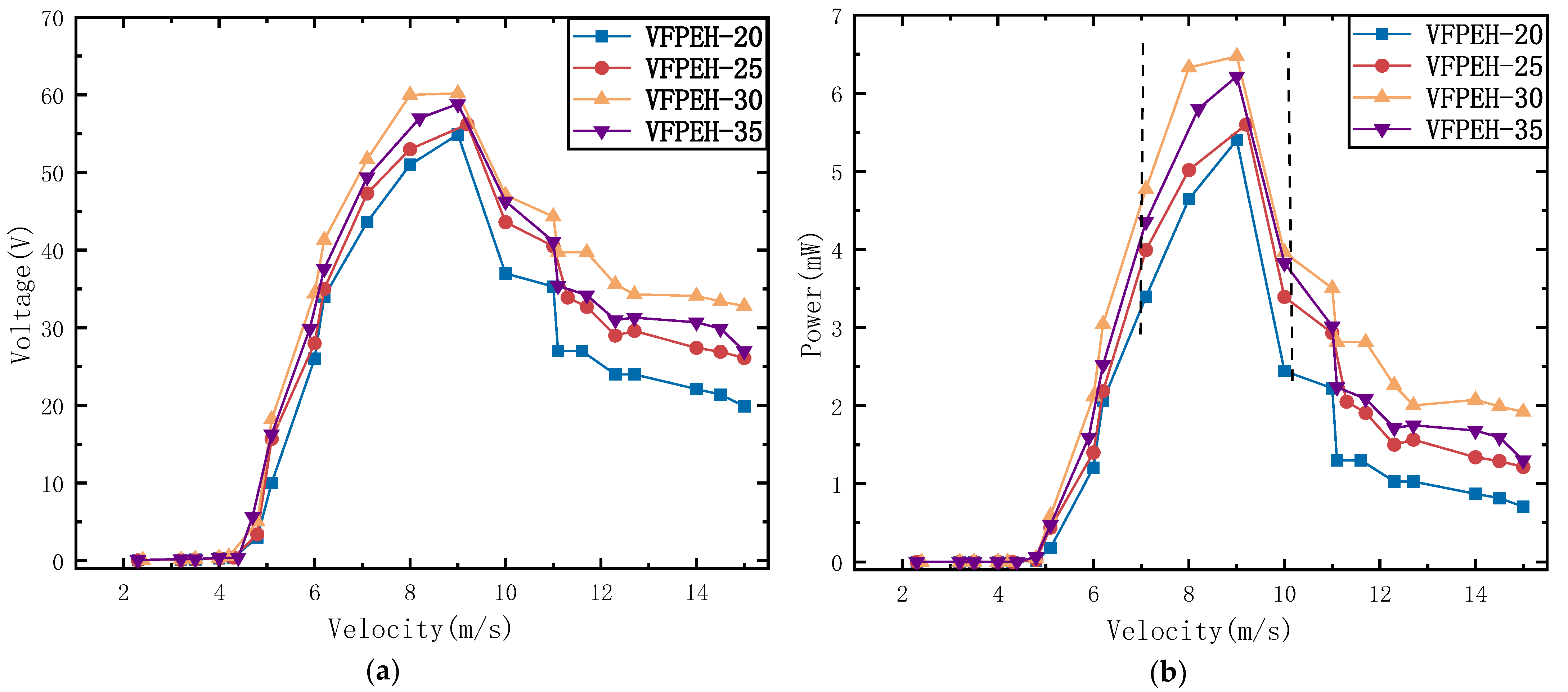
When we make experimental prototypes of different specifications, other dimensions are the same, and the diameter of cylindrical bluff body is 20 mm, 25 mm, 30 mm and 35 mm, respectively, which are, respectively, recorded as the prototypes VFPEH-20, VFPEH-25, VFPEH-30 and VFPEH-35. We study the output performance of each prototype with the wind velocity. Through multiple experiments and data collection, the curves of output voltage and output power of the VFPEH-20, VFPEH-25, VFPEH-30 and VFPEH-35 with wind velocity are drawn by using the obtained experimental data, as shown in Figure 3.
From Figure 3, that the trend of output voltage and output power with the wind velocity is basically the same for the prototypes with different diameters of cylindrical bluff bodies. When the wind velocity is less than 4.8 m/s, the VFPEH output voltage and output power is small and unstable. When the wind velocity exceeds the starting velocity of 4.8 m/s (the starting wind velocity of the VFPEH with four diameters is around 4.8 m/s), the output voltage and output power of the VFPEH increases rapidly and reaches its maximum value (wind velocity between 8.0 m/s and 9.0 m/s), and then decreases slowly with the increase in wind velocity. When the wind velocity is greater than 14 m/s, the output voltage and output power changes slightly with the increase in wind velocity. After reaching the maximum, the output of VFPEH gradually decreases with the increase in wind velocity because the cylindrical blunt body suppresses the occurrence of flutter during the energy harvest process.
It was found that from Figure 3, for the VFPEH with different cylinder bluff body diameters, with the increase in cylinder bluff body diameter, the voltage output slightly increases when the wind velocity is 4.8 m/s. When the diameter of the cylindrical bluff body is 20 mm, the maximum output voltage of VFPEH is 3.1 V, while the output voltage of VFPEH-35 reaches 5.7 V, an increase of 83.9%. When the wind velocity is greater than 4.8 m/s, with the increase in the wind velocity, the voltage output effect of VFPEH-30 with a cylindrical bluff body diameter of 30 mm is better than the other three VFPEH.
It can be seen from Figure 3 that when the wind velocity is 8.0 m/s–9.0 m/s, the output voltage and output power of the VFPEH reaches near its maximum value. Table 3 shows the maximum output voltage and maximum output power of four VFPEH with different bluff body diameters when the wind velocity is 8.0 m/s–9.0 m/s.
It can be seen from Figure 3b and Table 3 that when the diameter of cylindrical bluff body is 20 mm, the maximum output voltage and maximum output power of VFPEH-20 are the smallest compared with the other three sizes. When the diameter is 30 mm, the effect is the best, and the VFPEH output power maximum value is 6.47 mW. It can be seen from the position of the dotted line in Figure 3b that the VFPEH with a cylindrical bluff body with a diameter of 30 mm has a wider range of output power and wind velocity, the VFPEH-30 has a higher output for the same wind velocity and a greater range of wind velocities for the same output.

4.1.2. Load Resistance

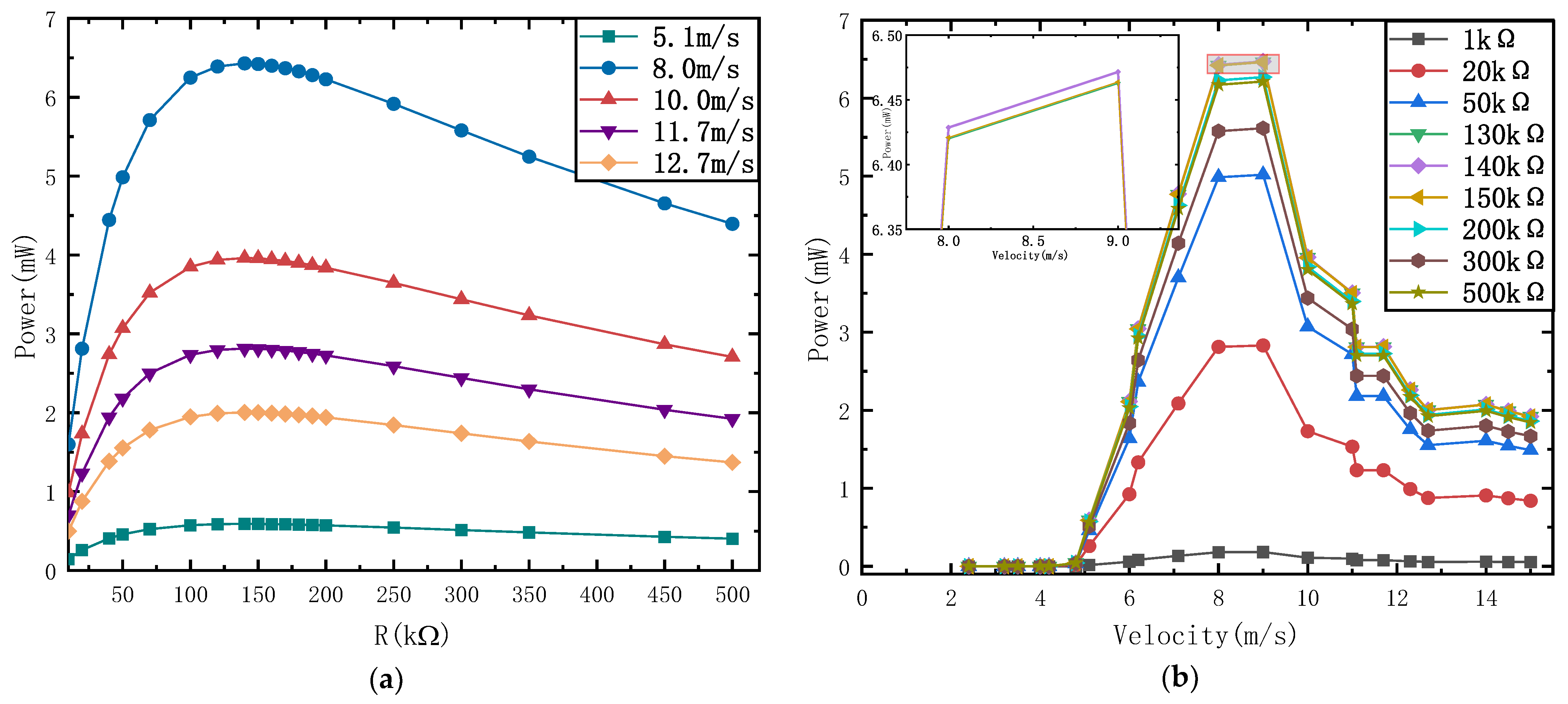
For different wind velocities, this paper tested the output power of VFPEH-30 at different load resistances, extracted the experimental data, and plotted the curves of the output power of VFPEH-30 with the load resistance at different wind velocities, and the curves of the power of VFPEH-30 with the wind velocity at different impedances, as shown in Figure 4a,b. The wind velocities of the experiment are 5.1 m/s, 8.0 m/s, 10.0 m/s, 11.7 m/s and 12.7 m/s, respectively, and the test range of matching resistance R was 1 kΩ–500 kΩ.
It can be seen from Figure 4a that under different wind velocities, the influence of the R on the output power of VFPEH-30 is consistent and nonlinear. With the same load resistance, the output power of VFPEH-30 increases and then decreases with the increase in wind velocity. When the load resistance R starts to increase from 1 kΩ, the output power of VFPEH-30 increases rapidly, reaches the maximum value between 130 kΩ–150 kΩ, and then decreases with the increase in R. Therefore, the matching load resistance of VFPEH-30 is between 130 kΩ–150 kΩ. When the wind velocity is 5.1 m/s, the output power of VFPEH-30 changes little with the increase in R. Therefore, the load resistance has little influence on the output power of the VFPEH-30 at low wind velocity. Figure 4b shows that when the R changes within the range of 1 kΩ–150 kΩ, the output power of VFPEH-30 under the same load resistance changes nonlinearly with the wind velocity, increases first and then decreases, and the change trend is basically the same, and the maximum output power has a certain wind velocity range. When the load resistance is 130 kΩ, 140 kΩ, and 150 kΩ, the maximum output power of VFPEH-30 is large. It can be seen from the local enlarged view in the figure that when the R is 140 kΩ, the output power reaches the maximum, so the best matching resistance is 140 kΩ.

4.2. Experimental Study of the Output Performance of the Energy Harvester

In order to study the output performance of VFPEH-30 and the coupling effect between vortex-induced vibration capture energy and flutter capture energy, vortex-induced piezoelectric energy harvester with a cylindrical bluff body diameter of 30 mm, and flutter piezoelectric energy harvester were fabricated, respectively, named veh-30 and FEH, and then relevant experiments were carried out. Compared with VFPEH-30, their piezoelectric cantilever module is the same as VFPEH-30, and the mass unit at the end of VEH-30 cantilever beam only contains cylindrical blunt body (hollow structures); the FEH cantilever beam contains only two symmetrically arranged wing-shaped components at the end of the beam. In order to eliminate the influence left by the previous flow rate experiment, the flow rate was reset for one minute after each test, and then the experiment was recorded [23].

4.2.1. Output Performance of VEH-30

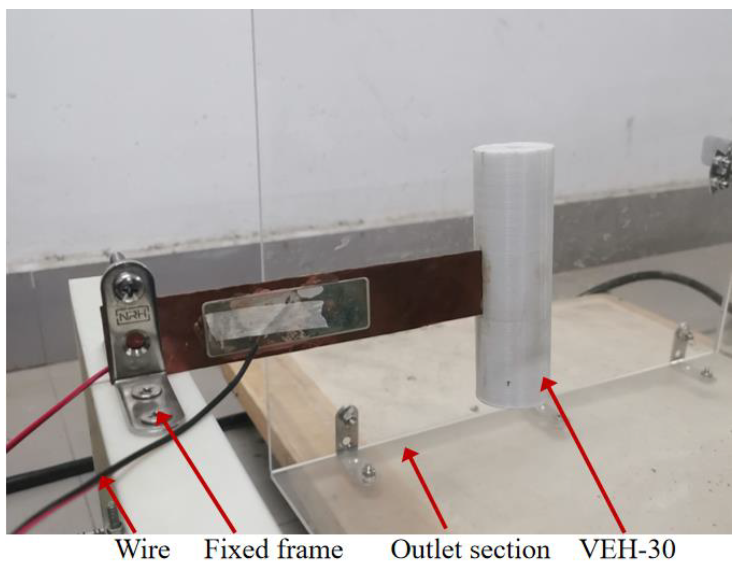
The VEH-30 consists of a cantilevered beam and a solid cylindrical bluff body. The cylindrical bluff body is fixed to the free end of the cantilevered beam. The upper surface of the cantilever is covered with piezoelectric sheet and placed 10 mm away from the fixed end of the cantilever. The size of the piezoelectric sheet is 60 mm × 20 mm × 0.2 mm. Due to the fluid-solid coupling effect, the cylindrical body deflects the beam when subjected to a vibrational force, which causes a strain inside the piezoelectric element and generates an electrical charge based on the piezoelectric effect [23]. When the output performance test of veh-30 is carried out in the wind tunnel, it is subject to stable and controllable air flow, and the maximum wind velocity is 14.5 m/s. A photo of a prototype VEH-30 energy harvester is shown in Figure 5. Table 4 shows the material parameters and dimensional parameters of VEH-30.
We extracted the experimental data, and drew the curve of the output voltage of VEH-30 changing with the wind velocity, as well as the maximum output voltage waveform of VEH-30 at different wind velocities, as shown in Figure 6.
From Figure 6a, it can be seen that in the wind velocity range of 2.0 m/s–15.0 m/s, when the wind velocity is less than 7.1 m/s, the output voltage of the VEH-30 harvester is less than 1 V; when the wind velocity is 7.1 m/s, the output voltage of the energy harvester is 1.10 V, which is considered as the starting wind velocity of the VEH-30; with the increase in wind velocity, the output voltage of the VEH-30 increases rapidly, when the wind velocity was 12.5 m/s, the output voltage reached a maximum of 3.59 V; thereafter, the output voltage decreased as the wind velocity increased. The maximum output voltage is reached at a wind velocity of 12.5 m/s because the intrinsic frequency of the VEH-30 resonates with the excitation frequency caused by the ambient wind velocity at this time, and the cantilever beam deformation amplitude is at its maximum, so that its output performance reaches its highest. As can be seen from Figure 6a, the VEH-30 has a small range of wind velocity bands to achieve relatively large voltage output. Figure 6b shows that the output voltage of the VEH-30 approximates the periodic and constant-amplitude, and the amplitude of the voltage output first increases and then gradually decreases with the increase in the airflow velocity.

4.2.2. Output Performance of FEH

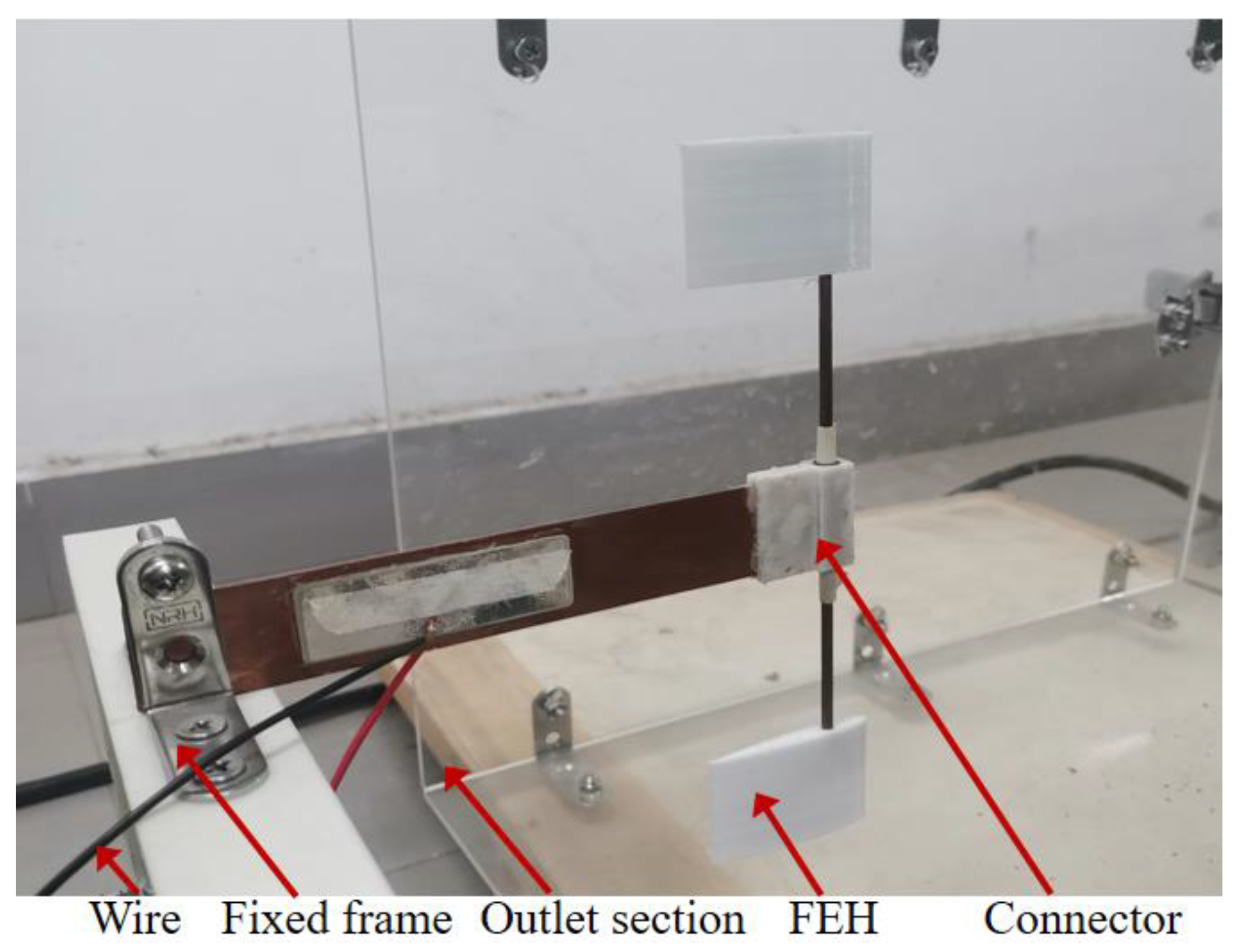
The FEH is composed of a cantilever beam (the same as VFPEH-30) and two airfoils fixed at both ends of the long axis and symmetrically distributed. The cantilever beam and the long axis are fixed by connectors obtained by 3D printing. Since the airfoil is small in size and formed by 3D printing, the material is light in mass and placed perpendicular to the air flow direction, so the influence of its gravity is ignored. Figure 7 illustrates the prototype of the FEH and Table 5 shows the material parameters and dimensional parameters of the FEH.
The experiments were carried out in a wind tunnel with one end open, and the maximum wind velocity was 14.5 m/s. Figure 8 is a point line diagram of the output voltage of FEH under different wind velocities and a waveform diagram of the output voltage over time.
As can be seen from Figure 8a, with the increase in wind velocity, the output voltage increases nonlinearly and finally reaches a stable state. When the wind velocity is less than 8.5 m/s, the vibration of FEH structure is small and unstable, and it is in a quasi-static state [45]. This is because the ground vibrates during the operation of the fan, which affects FEH, resulting in small voltage output and instability. Figure 8b shows the voltage waveform when the wind velocity is 7.9 m/s (less than the starting wind velocity), and the output voltage is 0.2 V. When the wind velocity is 8.5 m/s, the cantilever beam of the FEH vibrates with a large amplitude, and the output voltage of the FEH is 3.3 V. Combine this with Figure 8a, this wind velocity is considered as its starting wind velocity. When the wind velocity is greater than the starting wind velocity of 8.5 m/s, the output voltage gradually increases with the increase in wind velocity. After the wind velocity is 14.0 m/s, the voltage reaches stable output. When the wind velocity is 14.5 m/s, the output voltage is 9.53 V. Shown below is Figure 9, it is a phase diagram of the output voltage of FEH under different wind velocities.
It can be seen from Figure 9 that FEH produced limit cycle oscillation during the experiment. When the wind velocity is 7.90 m/s, the starting wind velocity is not reached, and the aerodynamic force on the symmetrically distributed airfoil components is uneven, resulting in more chaotic phase diagrams at the current velocity. The phase portraits of output voltage appear approximately as a single cycle, while the phase portrait does not appear to be very smooth, especially at 7.9 m/s. The reason is that there exist the unexpected disturbances in the experiment. When the wind velocity is 8.5 m/s, the aerodynamic damping of the energy trap exceeds the wind damping of the structure, resulting in aeroelastic motion in two degrees of freedom and corresponding limit cycle oscillation (LCO) [46]. The curves of the experimental results are not smooth, which is caused by environmental interference such as resonance generated by the wind turbine and the ground during the experiment.

4.2.3. Output Performance of VFPEH-30

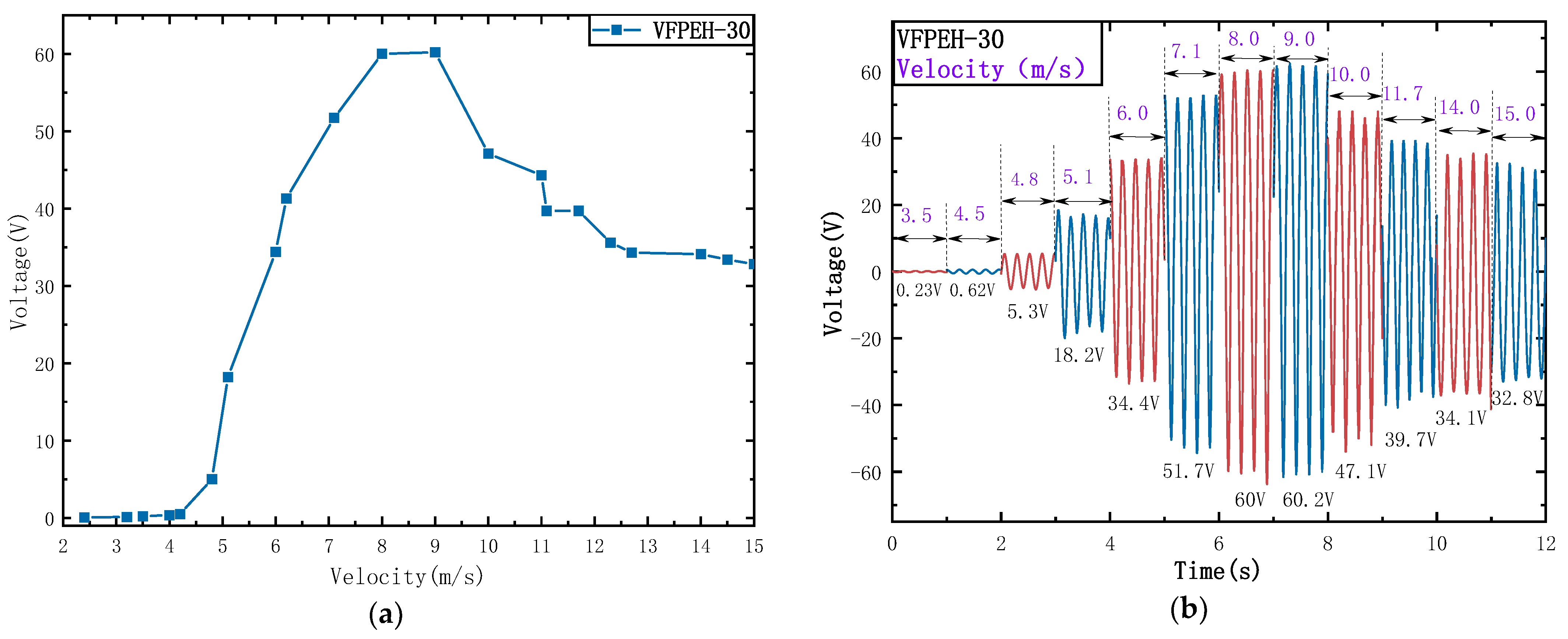
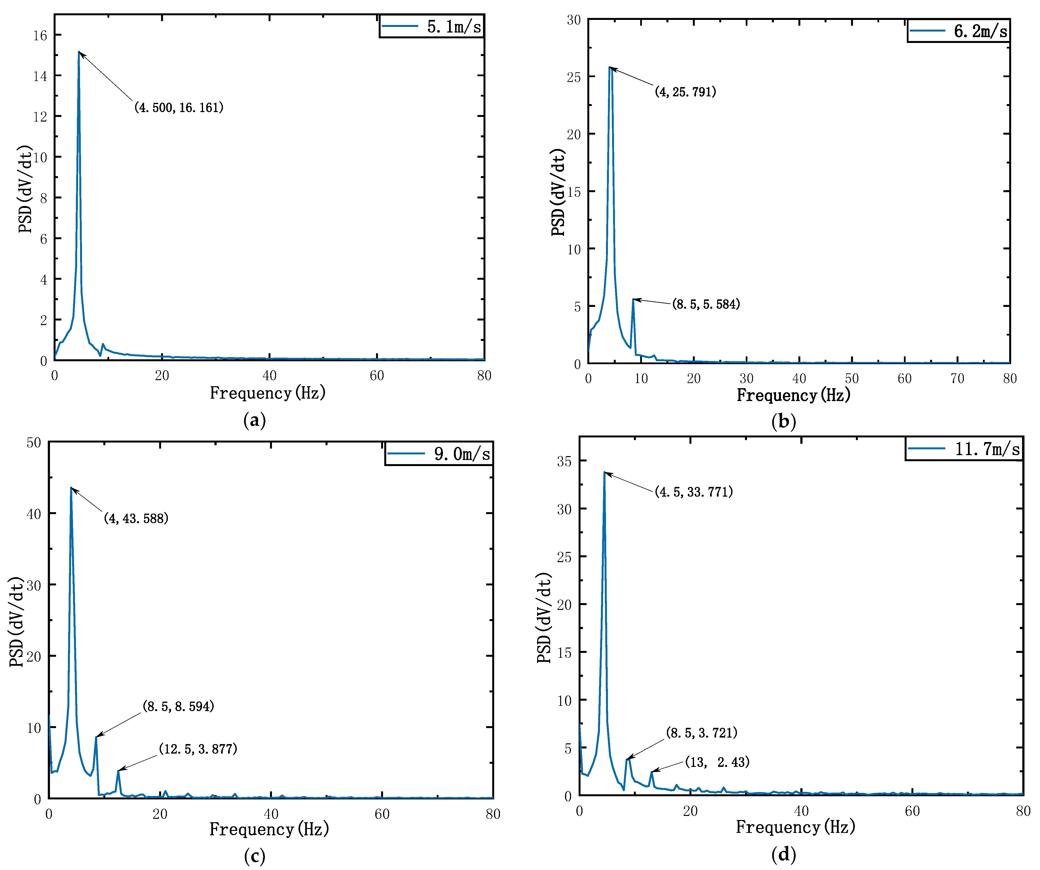
The output performance test of VFPEH-30, a hybrid energy trap for vortex-induced flutter of symmetric airfoils, was carried out under the same experimental conditions as EVH-30 and FEH. We extracted the experimental data, drew the VFPEH-30 output voltage curve (as shown in Figure 10) with the change in wind velocity, as well as the VFPEH-30 output voltage waveform (as shown in Figure 11) with different wind velocities, and the VFPEH-30 output power spectral density diagram (as shown in Figure 12).
Figure 10a shows that with the increase in wind velocity, the output voltage of the VFPEH-30 changes nonlinearly, first increasing and then gradually decreasing. The output voltage of VFPEH-30 is significantly higher than that of VEH-30 and FEH. When the wind velocity is less than 4.8 m/s, the output voltage is small. At this time, the captured energy is mainly generated by the vortex-induced vibration of the cylindrical blunt body, and the airfoil does not swing at low velocity [45]. When the wind velocity is 4.8 m/s, the VFPEH-30 has a large amplitude vibration. The airfoil starts to vibrate under the action of the wind. The output voltage of the VFPEH-30 is 5.3 V, and this wind velocity is its starting wind velocity. When the wind velocity is greater than 4.8 m/s, with the increase in wind velocity, the vibration amplitude of VFPEH-30 becomes larger and larger, and the output voltage increases rapidly; when the wind velocity is 8.0 m/s–9.0 m/s, the output voltage reaches the peak range. When the wind velocity is 9.0 m/s, the output voltage is the largest, 60.2 V. After that, with the increase in wind velocity, the output voltage of the VFPEH-30 decreases rapidly until the wind velocity is greater than 11.7 m/s, and the output voltage tends to be stable, both of which are greater than 30 V. Figure 11 shows a time story of the output voltage for the VFPEH-30 at wind speeds of 5.1, 6.2, 9.0 and 11.7 m/s. Compared to 6.2 m/s and 9.0 m/s, the irregular vibration response at 5.1 m/s is due to the relatively low vibration of the airfoil at lower wind speeds, 5.1 m/s, which causes less disturbance to the VFPEH-30. Whereas at higher wind velocities, the vibration of the airfoil is relatively higher, disturbing the VFPEH-30 more and subjecting it to higher aerodynamic forces, i.e., the vibration response is irregular.
From Figure 12, it was found that the output performance of VFPEH-30 is relatively poor when the wind velocity is 5.1 m/s, and the output voltage is 18.2 V. When the wind velocity is 9.0 m/s and 11.7 m/s, a higher quasi periodic output voltage can be generated, and the peak voltage is 60.2 V at 9.0 m/s. After fast Fourier transformation, the power density map can be obtained, as shown in Figure 12. As can be seen from Figure 12, with the increase in the air flow velocity, the fundamental frequency oscillation frequency does not change much and the frequency domain amplitude increases rapidly. The main harmonic is 4 Hz or 4.5 Hz under the four wind velocities, and the second and third harmonic oscillations occur, which indicates that VFPEH-30 is affected by aerodynamic nonlinearity in the process of energy capture, thus showing weak nonlinearity.

4.3. Analysis of Coupling Effect of Vortex-Induced Flutter Excitation

In the previous article, the output performance of the classical vortex-induced energy harvester VEH, the flutter energy harvester FEH and the composite energy harvester VFPEH were studied through experiments. The experimental results were extracted and the output voltage waveforms of the three energy harvesters at a wind velocity of 9.5 m/s were drawn (as shown in Figure 13a). Moreover, the curve diagrams of the output power of the three energy harvesters with the wind velocity when the load resistance is 140 kΩ are also drawn (as shown in Figure 13b).
As can be seen from Figure 13a, when the wind velocity is 9.5 m/s, the output performance of the VEH-30 is poor, and its output voltage is low, 2.7 V, because it only generates vortex-induced vibration under the action of air flow. Compared with VEH-30, FEH has a symmetrical flutter structure of two airfoils, and the vibration of the maneuvering airfoil improves its output performance to a certain extent. When the wind velocity is 9.5 m/s, the FEH output voltage is 5.2 V. The output voltage of VFPEH-30 is better than the superposition of VEH-30 and FEH. When the wind velocity is 9.5 m/s, its output voltage is 54.3 V, which is 20.1 times and 10.4 times that of VEH-30 and FEH, respectively.
The key data of the three energy harvesters in Figure 13b were extracted to draw Table 6. In Table 6, V0 is the starting wind velocity of the energy harvester, Vmax is the wind velocity corresponding to the maximum output voltage of the energy harvester within the experimental test wind velocity range, Umax and Pmax are the maximum output voltage and maximum output power (matching resistance is 140 kΩ).
From Figure 13b and Table 4, the following results can be obtained: (1) The starting wind velocity of VFPEH-30 is 4.8 m/s, which is much lower than that of VEH-30 and FEH of the same size: 7.1 m/s and 8.5 m/s. (2) In the experimental test wind velocity range, the peak wind velocity corresponding to the maximum output voltage of VFPEH-30 is 9.0 m/s, which is lower than the peak wind velocities of VEH-30 and FEH of 12.5 m/s and 14.5 m/s, it means that VFPEH-30 can obtain higher output voltage at lower wind velocity. (3) In the experimental test wind velocity range, the maximum output voltage of VFPEH-30 is 60.2 V and the maximum output power is 6.47 mW, which is 16.8 and 6.3 times higher than the maximum output voltage of the VEH (3.59 V, 0.05 mW) and FEH (9.53 V, 0.26 mW), respectively.
The cylindrical bluff body and airfoil of VFPEH-30 are hollow structures, while the cylindrical bluff body of VEH-30 is a solid structure. The mass of VEH-30 cylindrical bluff body is close to the sum of the cylindrical bluff body mass, the two airfoils and the long axis mass of VFPEH-30. When the incoming wind velocity is low, it needs more wind energy to overcome the bluff weight of the VEH-30 cylinder to make it vibrate. For the VFPEH-30, on the one hand, the windward surface of which is larger than that of the VEH-30, and on the other hand, the airfoil mass is small. When the energy of the incoming flow exceeds the gravitational energy of the airfoil, it can make the airfoil vibrate, and then induce the vibration of the cylindrical bluff body, so the starting wind velocity of the VFPEH-30 is much lower than that of the VEH-30. The mass element of FEH is symmetrically distributed airfoil and long axis. Its mass is small, but the windward surface is also small. When the air flows, the harvested wind energy per unit time is small, so its starting wind velocity is also large.
When the wind velocity is high, the symmetrically distributed airfoil of the VFPEH-30, on the one hand, together with the cylindrical bluff body, causes the cantilever beam to generate bending vibration, while with the hollow bluff body makes the structure not completely symmetrical due to manufacturing, assembly, etc., or reasons such as the two airfoils being excited by the wind energy which is not completely consistent, which induces the cantilever beam to produce torsional vibration [47]. The vortex-induced vibration generated by the cylindrical bluff body and the flutter generated by the airfoil work together, and the coupling of the bending vibration and the torsional vibration is the increase in the deformation of the cantilever beam, and then the internal strain of the piezoelectric ceramic sheet increases, and the potential difference generated on the upper and lower surfaces. That is, the output voltage is increased, so the VFPEH-30 can reach the maximum output at relatively low wind velocities, and at the same time, the harvested wind energy is much larger than that of the VEH-30 and FEH energy harvesters.
In order to test the performance of the energy harvester proposed in this paper, the composite energy harvester proposed in this paper is compared with the same type of energy harvester, and the energy harvesting characteristics of the energy harvester are quantitatively evaluated, as shown in Table 7. The energy harvesters compared are all piezoelectric energy harvesters that combine two energy harvesting mechanisms.
From the two structures mentioned in Table 7, it can be seen that the energy harvesting structure proposed in this paper has relatively good output performance. For example, Kwon proposed a T-shaped piezoelectric cantilever beam structure for fluid energy harvest, its output performance is better than that of Bryant and Garcia, which only contains airfoil structure and a single piezoelectric harvest energy. The composite structure of vortex excitation and flutter proposed in this paper is superior to the two and can effectively improve the maximum output voltage and output power.

5. Conclusions

In this paper, a vortex-induced flutter composite piezoelectric energy harvester is designed. The structure is a symmetrical arrangement of airfoils on both sides of the cylindrical bluff body, which can simultaneously realize both vortex-induced vibration energy harvest and flutter energy harvest. An experimental study on the influence of key parameters on its output performance was carried out, coupled with experimental research on the effect of vortex-induced vibration and flutter energy harvest. The main results are as follows:
(1) The piezoelectric energy harvester VFPEH-30 with a symmetrical arrangement of airfoils and cylindrical blunt body can play a role in reducing the starting wind velocity, which is 4.8 m/s, much lower than the classical cylindrical blunt body vortex excited piezoelectric energy harvester VEH-30 and the airfoil flutter piezoelectric energy harvester FEH, by 32.40% and 43.53%, respectively.
(2) The symmetrical arrangement of the airfoils on both sides of the cylindrical blunt body enables the cantilever beam of the energy harvester to produce bending and torsional compound vibrations, realizing energy harvest in both bending and torsional directions. It effectively increases its output voltage and output power. The effect of energy harvest varies from one cylindrical blunt body to another, between 20–35 mm. The energy harvest is better when the blunt body diameter is 30 mm, the output voltage of the VFPEH-30 first increases and then decreases with increasing air velocity. The results show that the maximum output power is 6.47 mW at a wind speed of 9.0 m/s and an optimum load of 140 k, which is much higher than that of the VEH-30 and FEH.
(3) Compared with the classical vortex-induced piezoelectric energy harvester and the flutter piezoelectric energy harvester, the vortex-induced and flutter composite piezoelectric energy harvester has a higher power output at a lower wind speed. This work provides an effective experimental basis for a combined vortex-flutter energy harvester with two mechanisms.

Author Contributions

X.L. and X.W. designed the model and carried out the experiment; X.L. and B.L. provided guidance; writing—original draft preparation, X.W.; writing—review and editing, X.L. and H.T.; C.W. provided experimental assistance. All authors have read and agreed to the published version of the manuscript.

Funding

This research was funded by Key Research Development and Promotion Project in Henan Province (Grant No. 22210221005).

Institutional Review Board Statement

Not applicable.

Informed Consent Statement

Not applicable.

Data Availability Statement

Not applicable.

Conflicts of Interest

The authors declare no conflict of interest.

References

  1. Sezer, N.; Koç, M. A Comprehensive Review on the State-of-the-art of Piezoelectric Energy Harvesting. Nano Energy 2021, 80, 105567. [Google Scholar]
  2. Yang, Z.B.; Zhou, S.X.; Jean, Z.; Daniel, I. High-Performance Piezoelectric Energy Harvesters and Their Applications. Joule 2018, 2, 642–697. [Google Scholar]
  3. Deterre, M.; Lefeuvre, E.; Zhu, Y.; Woytasik, M.; Boutaud, B.; Molin, R.D. Micro Blood Pressure Energy Harvester for Intracardiac Pacemaker. J. Microelectromech. Syst. 2014, 23, 651–660. [Google Scholar] [CrossRef]
  4. Hossain, I.Z.; Khan, A.; Hossain, G. A Piezoelectric Smart Textile for Energy Harvesting and Wearable Self-Powered Sensors. Energies 2022, 15, 5541. [Google Scholar] [CrossRef]
  5. Wang, H.; Jasim, A.; Chen, X. Energy Harvesting Technologies in Roadways and Bridges for Different Applications—A Comprehensive Review. Energy 2018, 212, 1083–1094. [Google Scholar]
  6. Su, Y.; Zhang, K.; Gong, Q. Theoretical and experimental study of an elect-romagnetic vibration energy harvester. Ferroelectrics 2019, 551, 69–87. [Google Scholar] [CrossRef]
  7. Kamenar, E.; Zelenika, S.; Blažević, D.; Maćešić, S.; Gregov, G.; Marković, K.; Glažar, V. Harvesting of River Flow Energy for Wireless Sensor Network Technology. Microsyst. Technol. Sens. Actuators Syst. Integr. 2015, 22, 1557–1574. [Google Scholar] [CrossRef]
  8. Evans, M.; Tang, L.; Tao, K.; Aw, K. Design and Optimisation of an Underfloor Energy Harvesting System. Sens. Actuators A Phys. 2019, 285, 613–622. [Google Scholar] [CrossRef]
  9. Lim, Y.Y.; Padilla, R.V.; Unger, A.; Barraza, R.; Thabet, A.M.; Izadgoshasb, I. A Self-tunable Wind Energy Harvester Utilising a Piezoelectric Cantilever Beam with Bluff Body under Transverse Galloping for Field Deployment. Energy Convers. Manag. 2021, 245, 114559. [Google Scholar] [CrossRef]
  10. Rojas, F.E.; Faroughi, S.; Abdelkefi, A.; Park, Y.H. Investigations on the Performance of Piezoelectric-flexoelectric Energy Harvesters. Appl. Energy 2021, 288, 116611. [Google Scholar] [CrossRef]
  11. Imbaquingo, C.; Bahl, C.; Insinga, A.R.; Bjørk, R. A Two-dimensional Electromagnetic Vibration Energy Harvester with Variable Stiffness. Appl. Energy 2022, 325, 119650. [Google Scholar] [CrossRef]
  12. Zhang, Y.; Wang, T.; Luo, A.; Hu, Y.; Li, X.; Wang, F. Micro electrostatic energy harvester with both broad bandwidth and high normalized power density. Appl. Energy 2018, 212, 362–371. [Google Scholar] [CrossRef]
  13. Kumar, S.; Singh, D.; Kumar, R.; Jain, S.C. No-Wear Vibration Energy Harvester Based on a Triboelectric Mechanism. J. Electron. Mater. 2021, 50, 7057–7070. [Google Scholar] [CrossRef]
  14. Zhao, X.; Shang, Z.; Luo, G.; Deng, L. A Vibration Energy Harvester Using AlN Piezoelectric Cantilever Array. Microelectron. Eng. 2015, 142, 47–51. [Google Scholar] [CrossRef]
  15. Lai, Z.; Wang, S.; Zhu, L.; Zhang, G.; Wang, J.; Yang, K.; Yurchenko, D. A Hybrid Piezo-dielectric Wind Energy Harvester for High-performance Vortex-induced Vibration Energy Harvesting. Mech. Syst. Signal Process. 2021, 150, 107212. [Google Scholar] [CrossRef]
  16. Mehdipour, I.; Madaro, F.; Rizzi, F.; de Vittorio, M. Comprehensive Experimental Study on Bluff Body Shapes for Vortex-induced Vibration Piezoelectric Energy Harvesting Mechanisms. Energy Convers. Manag. X 2022, 13, 100174. [Google Scholar] [CrossRef]
  17. Liu, J.; Bao, B.; Chen, J.; Wu, Y.; Wang, Q. Passively Adaptive Wind Energy Harvester Featuring a Double-airfoil Bluff Body with Adjustable Attack Angles. Mech. Syst. Signal Process. 2023, 185, 109814. [Google Scholar] [CrossRef]
  18. Stefano, O.; Boccalero, G.; Mazzino, A.; Boragno, C. Fluttering Conditions of an Energy Harvester for Autonomous Powering. Energy 2017, 105, 530–538. [Google Scholar]
  19. Ming, X.; Wang, B.; Li, X.; Zhou, S.; Yurchenko, D. Dynamic Response Mechanism of the Galloping Energy Harvester under Fluctuating Wind Conditions. Mech. Syst. Signal Process. 2022, 166, 108410. [Google Scholar]
  20. Yili, H.; Yang, B.; Chen, X.; Wang, X.; Liu, J. Modeling and Experimental Study of a Piezoelectric Energy Harvester from Vortex Shedding-induced Vibration. Energy Convers. Manag. 2018, 162, 145–158. [Google Scholar]
  21. Dai, H.L.; Abdelkefi, A.; Yang, Y.; Wang, L. Orientation of Bluff Body for Designing Efficient Energy Harvesters from Vortex-induced Vibrations. Phys. Lett. 2016, 108, 53902. [Google Scholar] [CrossRef]
  22. Shengxi, Z.; Wang, J. Dual Serial Vortex-induced Energy Harvesting System for Enhanced Energy Harvesting. AIP Adv. 2018, 8, 075221. [Google Scholar]
  23. Akaydin, H.D.; Elvin, N.; Andreopoulos, Y. The Performance of a Self-excited Fluidic Energy Harvester. Smart Mater. Struct. 2012, 21, 025007. [Google Scholar] [CrossRef]
  24. Junlei, W.; Ran, J.; Zhang, Z. Energy Harvester Based on the Synchronization Phenomenon of a Circular Cylinder. Math. Probl. Eng. 2014, 2014, 1–9. [Google Scholar]
  25. Weipeng, S.; Zhao, D.; Tan, T.; Yan, Z.; Guo, P.; Luo, X. Low Velocity Water Flow Energy Harvesting Using Vortex Induced Vibration and Galloping. Energy 2019, 251, 113392. [Google Scholar]
  26. Weinstein, A.L.; Cacan, M.R.; So, P.M.; Wright, P.K. Vortex Shedding Induced Energy Harvesting from Piezoelectric Materials in Heating, Ventilation and Air Conditioning Flows. Smart Mater. Struct. 2012, 21, 45003. [Google Scholar] [CrossRef]
  27. Xia, L.; Li, Z.; Bi, C.; Liu, B.; Su, Y. Study on Wind Energy Harvesting Effect of a Vehicle-Mounted Piezo-Electromagnetic Hybrid Energy Harvester. IEEE Access 2020, 8, 167631–167646. [Google Scholar]
  28. Fei, F.; Zhou, S.; Mai, J.D.; Li, W.J. Development of an Indoor Airflow Energy Harvesting System for Building Environment Monitoring. Energies 2014, 7, 2985–3003. [Google Scholar] [CrossRef] [Green Version]
  29. Soon-Duck, K. A T-shaped Piezoelectric Cantilever for Fluid Energy Harvesting. Phys. Lett. 2010, 97, 164102. [Google Scholar]
  30. Dunnmon, J.A.; Stanton, S.C.; Mann, B.P.; Dowell, E.H. Power Extraction from Aeroelastic Limit Cycle Oscillations. J. Fluids Struct. 2011, 27, 1182–1198. [Google Scholar] [CrossRef]
  31. Bryant, M.; Wolff, E.; Garcia, E. Parametric design study of an aeroelastic flutter energy harvester. Proc. SPIE 2011, 7977, 1–11. [Google Scholar]
  32. Ngan, T.; Ghayesh, M.H.; Arjomandi, M. Ambient Vibration Energy Harvesters: A Review on Nonlinear Techniques for Performance Enhancement. Int. J. Eng. Sci. 2018, 127, 162–185. [Google Scholar]
  33. Mahmoudi, S.; Kacem, N.; Bouhaddi, N. Enhancement of the Performance of a Hybrid Nonlinear Vibration Energy Harvester Based on Piezoelectric and Electromagnetic Transductions. Smart Mater. Struct. 2014, 23, 75024. [Google Scholar] [CrossRef]
  34. Masood, A.M.; Khan, F.U. Review of Vibration-based Electromagnetic–piezoelectric Hybrid Energy Harvesters. Int. J. Energy Res. 2021, 45, 5058–5097. [Google Scholar]
  35. Kui, L.; Yang, Z.; Gu, Y.; He, S.; Zhou, S. Nonlinear Magnetic-coupled Flutter-based Aeroelastic Energy Harvester: Modeling, Simulation and Experimental Verification. Smart Mater. Struct. 2018, 28, 15020. [Google Scholar]
  36. Rawnak, H.; Yuce, M.R. A Wearable Energy Harvester Unit Using Piezoelectric-electromagnetic Hybrid Technique. Sens. Actuators A Phys. 2017, 257, 198–207. [Google Scholar]
  37. Zhongjie, L.; Al-Riyami, M.; Bahadur, I.; Ouakad, H. There Is Plenty of Room inside a Bluff Body: A Hybrid Piezoelectric and Electromagnetic Wind Energy Harvester. Energies 2022, 15, 6097. [Google Scholar]
  38. Junlei, W.; Gu, S.; Zhang, C.; Hu, G.; Chen, G.; Yang, K.; Li, H.; Lai, Y.; Litak, G.; Yurchenko, D. Hybrid Wind Energy Scavenging by Coupling Vortex-induced Vibrations and Galloping. Energy Convers. Manag. 2020, 213, 112835. [Google Scholar]
  39. Xiaobiao, S.; Tian, H.; Cao, H.; Xie, T. Enhancing Performance of a Piezoelectric Energy Harvester System for Concurrent Flutter and Vortex -induced Vibration. Energies 2020, 13, 3101. [Google Scholar]
  40. Atrah, A.B.; Ab-Rahman, M.S.; Salleh, H.; Nuawi, M.Z.; Nor, M.J.M.; Jamaludin, N.B. Karman Vortex Creation Using Cylinder for Flutter Energy Harvester Device. Micromachines 2017, 8, 227. [Google Scholar] [CrossRef] [Green Version]
  41. Chengwei, H.; Shan, X.; Zhang, L.; Song, R.; Yang, Z. Design and Modeling of a Magnetic-Coupling Monostable Piezoelectric Energy Harvester Under Vortex-Induced Vibration. IEEE Access 2020, 8, 108913–108927. [Google Scholar]
  42. Zhiyuan, L.; Li, X.; Liu, B.; Wang, J. Influence of Vehicle Body Vibration Induced by Road Excitation on the Performance of a Vehicle-mounted Piezoelectric-electromagnetic Hybrid Energy Harvester. Smart Mater. Struct. 2021, 30, 55019. [Google Scholar]
  43. Miguel, P.; Doaré, O.; Michelin, S. Influence and Optimization of the Electrodes Position in a Piezoelectric Energy Harvesting Flag. J. Sound Vib. 2015, 346, 200–215. [Google Scholar]
  44. Nishigaki, T. Development of a piezoelectric polymer energy harvestin-g flag. Act. Passiv. Smart Struct. Integr. Syst. 2013, 8688, 1–7. [Google Scholar]
  45. Sousa, V.C.; de M. Anicézio, M.; De Marqui, C., Jr.; Erturk, A. Enhanced Aeroelastic Energy Harvesting by Exploiting Combined Nonlinearities: Theory and Experiment. Smart Mater. Struct. 2011, 20, 094007. [Google Scholar] [CrossRef]
  46. Abdelkefi, A.; Nayfeh, A.H.; Hajj, M.R. Modeling and Analysis of Piezoaeroelastic Energy Harvesters. Nonlinear Dyn. 2011, 67, 925–939. [Google Scholar] [CrossRef]
  47. Dias, J.A.C.; De Marqui Jr, C.; Erturk, A. Hybrid Piezoelectric-inductive Flow Energy Harvesting and Dimensionless Electroaeroelastic Analysis for Scaling. Phys. Lett. 2013, 102, 44101. [Google Scholar] [CrossRef]
Figure 1. Schematic diagram of the VFPEH.
Applsci 12 12514 g001
Figure 2. Experimental platform: (a) Energy harvest system; (b) Enlarged view of VFPEH.
Applsci 12 12514 g002
Figure 3. Output performance of the VFPEH at different cylindrical bluff diameters: (a) Output voltage; (b) Output power (matching resistance is 140 kΩ).
Applsci 12 12514 g003
Figure 4. Influence of key parameters on the output power of the VFPEH-30: (a) Curves of the output power with load under different wind velocities; (b) Curves of output power with the wind velocity under different loads.
Applsci 12 12514 g004
Figure 5. Enlarged view of VEH-30.
Applsci 12 12514 g005
Figure 6. VEH-30 at different wind velocities: (a) Output voltage graph; (b) Voltage versus time graph.
Applsci 12 12514 g006
Figure 7. Enlarged view of FEH.
Applsci 12 12514 g007
Figure 8. FEH output voltage: (a) Output voltage curve with wind velocity; (b) Voltage waveform with time.
Applsci 12 12514 g008
Figure 9. Phase diagram of FEH at different wind velocities: (a) Wind velocity of 7.9 m/s; (b) Wind velocity of 10.2 m/s; (c) Wind velocity of 11.5 m/s; (d) Wind velocity of 14.0 m/s.
Applsci 12 12514 g009
Figure 10. Output characteristics of the VFPEH-30: (a) Output voltage curve at different wind velocities; (b) Output voltage waveform.
Applsci 12 12514 g010
Figure 11. Time story of output voltage for VFPEH-30 at different wind velocities: (a) 5.1m/s and 6.2m/s; (b) 9.0m/s and 11.7 m/s.
Applsci 12 12514 g011
Figure 12. Power spectral density (PSD) plot of the VFPEH-30 at different wind velocities: (a) 5.1 m/s; (b) 6.2 m/s; (c) 9.0 m/s; (d) 11.7 m/s.
Applsci 12 12514 g012
Figure 13. Output characteristics of three energy harvesters: (a) Output voltage; (b) Output power.
Applsci 12 12514 g013
Table 1. Materials and parameters of each part of the VFPEH.
PropertiesSubstratesPiezoelectric SheetsBluff BodyShaftBearings
MaterialsCopper alloyPZT-5HPLACopperBearing steel
Density (kg/m3)89007500125087007810
Young’s modulus (GPa)105663.5119-
Poisson’s ratio0.350.3-0.32-
Length (mm)14060100150-
Width/Diameter (mm)262020–350.36
Thickness (mm)0.40.2--2.5
Table 2. NACA0012 wing dimensional parameters.
PropertiesAirfoil
MaterialsPLA
Density (kg/m3)1250
Young’s modulus (GPa)3.5
VFPEH captive energy mass (g)72.4
Cantilever beam mass (substrate and PZT) (g)20.1
airfoil mass (g)8.4
Connecting shaft mass (shaft and bearing) (g)9.9
Cylindrical mass (g)50.5
Span (mm)50
Half chord (mm)18
Airfoil axis position (mm)15
Table 3. Output characteristics of the VFPEH with different diameters.
Harvester TypeVFPEH-20VFPEH-25VFPEH-30VFPEH-35
Diameter (mm)20253035
Maximum output voltage Umax (V)54.956.260.258.8
maximum output power Pmax (mW)5.405.606.476.22
Table 4. Materials and parameters of each part of the VEH-30.
PropertiesSubstratesPiezoelectric SheetsBluff Body
MaterialsCopper alloyPZT-5HPLA
Density (kg/m3)890075001250
Young’s modulus (GPa)105663.5
Poisson’s ratio0.350.3-
Length (mm)14060100
Width/Diameter (mm)262030
Thickness (mm)0.40.2-
Table 5. Materials and parameters of each part of the FEH.
PropertiesSubstratesPiezoelectric SheetsConnectorShaftBearings
MaterialsCopper alloyPZT-5HPLACopperBearing steel
Density (kg/m3)89007500125087007810
Young’s modulus (GPa)105663.5119-
Poisson’s ratio0.350.3-0.32-
Length (mm)14060-150-
Width/Diameter (mm)2620-0.36
Thickness (mm)0.40.2--2.5
Table 6. Key characteristics of the three energy harvesters.
V0 (m/s)Vmax (m/s)Umax (V)Pmax (W)
VEH-307.112.53.590.05
FEH8.514.59.530.26
VFPEH-304.89.060.206.47
Table 7. Comparison of the proposed and existing energy harvesters.
ReferenceMechanismAirflow Velocity (m/s)Output Power (mW)
Bryant and Garcia [31]Piezoelectric8.02.20
Kwon [29]Piezoelectric4.04.00
This workPiezoelectric9.06.47
Publisher’s Note: MDPI stays neutral with regard to jurisdictional claims in published maps and institutional affiliations.