Abstract
This paper presents a transient-dynamic method (TDM), to investigate the dynamic responses of a railway formation under a train moving load using a three-dimensional finite element model. First, the feasibility of the TDM was verified, by comparing the vertical stress in a railway formation calculated using this method with the steady-state method (SSM). Next, the effects of train speed and embankment stiffness on the dynamic response of the railway formation were evaluated using TDM. The numerical results indicated that the vertical displacement/stress of the railway formation were remarkably increased with an increased train speed, within the shear wave velocity of the soft soil. In contrast, the vertical displacement/stress attenuation with the depth of the ground caused by high-speed trains was faster than that caused by low-speed trains. As for the effect of embankment stiffness, the enhancement of embankment stiffness had little effect on the transfer of vertical stress to the underlying soil. Finally, a determination of the dynamic stress for different train speeds was evaluated. This design code may underestimate the dynamic stress in a railway formation in high-speed situations (e.g., v = 112 m/s).
1. Introduction
To better understand the influences of various factors such as train speed on the performance of railway structures, the dynamic analysis of railway formations under a train load has become increasingly in-depth. Some existing works [1,2,3] reported that under higher train speed conditions, the railway track and underlying ground show significant vibrations, with a substantial vertical displacement or dynamic stress. Therefore, it is essential to study the dynamic response of the track formation on soft soil under moving train loads.
The vibration of the railway structure was commonly affected by the train speed, axle load, embankment height, and stiffness. Many scholars [4,5,6,7,8,9] discussed the effect of these factors according to experimental, analytical, or semi-analytical methods. For example, Fu et al. [10] studied the vibration velocities of a piled raft supported embankment and foundations in soft soil, with different underground water levels, using an experimental method. Sheng et al. [11] investigated the ground vibration of a semi-infinite space superposition beam model of layer soils under static and dynamic harmonic loads. Bian and Chen [12] proposed a time-domain semi-analytical solution, to analyze ground responses under moving loads, while considering various vehicle velocities. Zhan et al. [3] studied the dynamic response of slab track in soft soil under a moving train load using a semi-analytical method. The research indicated that the vibration of soft soil under the conditions of a high-speed train is more obvious than under the condition of a low-speed train.
On the other hand, the vibration behavior of the track formation has also been investigated based on numerical simulations [13,14,15,16,17,18,19]. For example, the dynamic response of subsoil under the static and dynamic loads of moving trains was studied by [20,21]. In addition, a numerical model was proposed by Takemiya and Bian [22], to analyze changes in track vibration and train speed. The results showed that a high-speed train causes a sizeable dynamic response. Auersch [23] pointed out that train speed and soil stiffness jointly affect the vibration of subgrade soil. Bian et al. [24] established a 2.5 D FEM, to simulate the layered soil vibration caused by high-speed trains. The results showed that track irregularities with a smaller wavelength caused greater vibration than those with a longer wavelength. More importantly, the stress–time history of a beam bridge under a dynamic moving load was calculated using the transient dynamic method (TDM) by Zhang et al. [25].
The above research demonstrated that train speed makes a remarkable contribution to the vibration of railway structures. However, it is difficult to deal with nonlinear and geometrically complex problems in engineering practice using the analytical method. The data obtained by field measurements and laboratory model tests under complex practical conditions have a high reference value, but the cost is high and the process is time-consuming. With the development of high-performance computers, various numerical methods have been widely used to solve the dynamic response problem of variation for geotechnical problems. On the basis of existing studies and combined with the principle of elastic dynamics, this paper established a coupled dynamics model of a train-ballastless track-layered subgrade-foundation. The transient dynamic method (TDM) was used to analyze the dynamic response of the railway formation under a high-speed train load. First, by comparing the results of the SSM recommended in the code design [26], the reliability of the proposed method in analyzing the vibration response of a railway line was verified. Then, the effects of train speed and embankment stiffness on the dynamic responses of tracks on soft soils, induced by moving train loads, were evaluated. The attenuation of the vertical stress through the depth in the subgrade under different conditions was studied, to provide a reference for the foundation treatment and structural design of high-speed railways in soft soil areas.
2. 3-D Numerical Simulations
2.1. Model Size and Parameters
The numerical models used for the simulation were constructed in ADINA. The analytical model shown in Figure 1 refers to the specific dimensions of a typical section of a Chinese railway structure. Figure 2 shows the specific dimensions of the calculated model, including the rail, concrete track slab, roadbed, subgrade, and foundation, from top to bottom, which are 400 m, 94 m, and 40 m, respectively. The input parameters for numerical simulations are listed in Table 1, referring to Zeng [27]. In the transient dynamic analysis, the damping coefficient of the structural system was given as the input parameter of the model, by means of modal analysis. In this study, it was assumed that the damping force of the structure was equal to the equivalent viscous damping and proportional to the displacement velocity and strain velocity. In this case, the Rayleigh linear combination method was used for the numerical analysis, to calculate the damping coefficient. It should be noted that the corresponding parameters for the train speed and embankment stiffness (i.e., roadbed and subgrade) should be changed in the parametric analysis. Moreover, to evaluate the effects of train speed and embankment stiffness on the dynamic response of the high-speed railway formation, three different train speeds (v = 56 m/s (200 km/h), 83 m/s (300 km/h), and 112 m/s (400 km/h)) were analyzed, since the current operating speed of Chinese high-speed railways has reached 350 km/h. In addition, three different embankment stiffnesses (roadbed stiffness of 105 MPa and subgrade stiffness of 35 MPa (E1); roadbed stiffness of 150 MPa and subgrade stiffness of 50 MPa (E2); and roadbed stiffness of 225 MPa and subgrade stiffness of 75 MPa (E3)) were selected, according to previous research by Zeng [27].
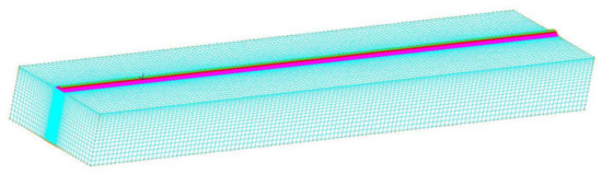
Figure 1.
The 3-D FEM for the railway structure.
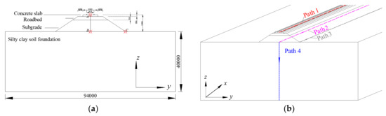
Figure 2.
Dimensions of the railway structure: (a) point; (b) path.

Table 1.
Parameters of the railway structure.
2.2. Constitutive Model of Soil and Boundary Conditions
In general, the stress–strain curve of a soil such as subgrade material is nonlinear and belongs to the elastic–plastic deformation. However, the dynamic strain value of subgrade soil under the action of traffic loads was small, and the magnitude of dynamic strain was less than 10−5. Therefore, a linear elastic constitutive model for layered soil was adopted in this study, which can, not only guarantee the solution accuracy, but also reduce the calculation time cost. In addition, in a numerical simulation, the reflection of a stress wave at the artificial cut-off boundary will affect the numerical results and produce certain errors. In fact, the foundation soil is a semi-infinite space, and the stress wave will be transmitted to infinity, so this would affect the calculation results and accuracy of the finite element analysis model. Thus, a visco-elastic artificial boundary was adopted in this study, to eliminate the influence of vibration waves at the boundary.
2.3. Simulation of a Train Moving Load
The calculation theory of vertical loads in code design [24] adopts a loading scheme (Figure 3) as a vertical design load for passenger railways. In this code, the design values of a vertical load should not be less than the real values induced by a moving train load and the track weight. This means that the vertical load on the track was calculated according to the sum of the moving train load and the track weight. The vertical load on the track (Figure 3) could be obtained by referring to Table 2. In this study, the correctness of the numerical analysis was checked by comparing the vertical stress on the railway ground obtained by TDM and SSM. For the SSM, the vertical stress on the railway formation was solved with a uniform load of 54.3 kPa (CRTS I, in Table 2), based on steady-state theory. In addition, for TDM, the moving load of the train (two carriages) shown in Figure 4 was simplified through four pairs of concentrated loads. In order to simplify the calculation, the amplitude of the concentrated load was a constant, with different moving speeds in the x direction, which could be calculated using the axle load of a typical train. It is noted that the model size and the related structural physical parameters adopted by the two calculation methods are the same.
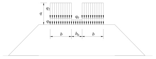
Figure 3.
Distribution of vertical load in the code design. Note: q0 is the line load; q1 is the track weight; q2 is the train load; q is the total load; b is width of the track load; b0 is the width of uniform load for backfilling between two lines.
Table 2.
Uniform loads induced by the track and train.
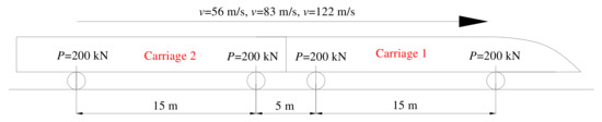
Figure 4.
Simplified train loads in the numerical analysis.
2.4. Verification of the TDM Results
As mentioned previous, in the current code design, the vertical load on the track surface can be assumed to be a uniformly distributed load and was solved using the steady-state method. However, the vertical stress on a railway formation induced by moving train load is affected by speed. It seems that the vertical stress calculation method recommended in the current code cannot truly reflect the vertical stress distribution of the railway structure. In this case, Figure 5 shows a comparison of vertical stress on the railway ground calculated using SSM with that using TDM. When the train speed was 83 m/s, the vertical stress values based on TDM were close to those obtained by SSM, proving that TDM was reasonable for numerical analysis. It should be noted that the vertical stresses on railway structures calculated by TDM were related to train speed, which will be discussed in the next section.
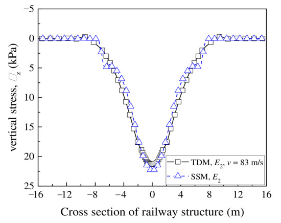
Figure 5.
Vertical stress in a cross-section of the railway ground.
3. Analysis of Numerical Results
3.1. Dynamic Response of the Railway Structure
For the analysis model shown in Figure 2, three monitoring points (Point A, Point B, and Point C) and four monitoring paths (Path 1, Path 2, Path 3, and Path 4) were selected, to study the dynamic response of the railway structure under a train load. Here, Point A is in the middle of two rails on the slab surface, with the x-axis coordinate of 200 m; Point B is directly below Point A, at the interface between the foundation and subgrade; Point C is at the embankment toe, and Points A, B, and C are on the same zoy plane. In this case, the train speed (v) of 83 m/s and the time (t) of 0.996 s were selected as the analysis conditions. The reason for choosing these positions as monitoring points was to observe the vibration behavior of the soil during the train running, ignoring the effect of boundary conditions in the x direction. Moreover, the vibration at the center of the slab surface, the foundation surface, and the embankment toe can effectively reflect the maximum vibration value and the attenuation law of the vibration in the depth and width directions of the entire railway structure under a train load.
Figure 6 presents the variations of acceleration (a) and displacement (d) with time at different monitoring points, respectively. As shown in this figure, both a and d in the z direction are larger than in the x and y directions. This indicates that the vibration of the railway track under a train load is mainly generated in the vertical direction. Therefore, the dynamic response in the vertical direction will be emphasized in the subsequent analysis. As for the a on track surface, there are four distinct acceleration peaks (Figure 6a), due to four pairs of concentrated loads being applied to the rail. Moreover, at point A, the amplitude of the positive a is much larger than that of the negative acceleration. However, as the vibration is transmitted into the ground, the two acceleration peaks at the middle position are gradually superposed, and the positive and negative amplitudes tend to become equal, as shown in Figure 6c,e. On the other hand, a peak displacement is also generated, due to the superposition of the displacement near to the position of the middle two pairs of loads, as shown in Figure 6b,d,f. In general, without considering the effect of train speed, the vertical displacement caused by symmetric concentrated loads is symmetrically distributed along the longitudinal direction of the track. However, an asymmetry of the vertical displacement in railway structures is caused by vibrations of the track structure under a moving load. Moreover, due to the effect of structural damping, the peak vertical displacement lags at the load position, and the vertical displacement caused by the wheel load at the train’s rear is not equal to the vertical displacement caused by the wheel load at the front of the train.
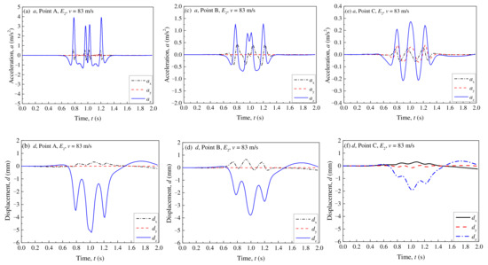
Figure 6.
Changes in the acceleration and displacement with time at different points: (a) a, Point A; (b) a, Point B; (c) a, Point C; (d) d, Point A; (e) d, Point B; (f) d, Point C.
Considering that the dynamic response of a railway structure is mainly generated in the vertical direction, Figure 7 shows the vertical acceleration (az) and vertical displacement (dz) at Points A, B, and C. By comparing the az and dz at these points, it can be seen that the maximum values of az and dz at Point A are the largest, followed by Point B and Point C. This means that the vertical acceleration and displacement along the track surface and into railway ground are gradually attenuated. In addition, both az and dz at Point B are larger than those at Point C, indicating that the soil below the center of the rail is mainly affected by the train loads.
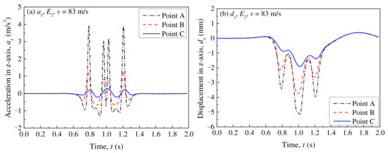
Figure 7.
Vertical acceleration/displacement at different points: (a) az; (b) dz.
To further analyze the trend of az and dz in the railway structure, Figure 8 shows the normalized maximum az and dz at different monitoring points. Compared with the attenuation trend of az, dz is slowly attenuated in the ground, irrespective of the monitoring points. To be specific, the dz from Point A to Point B drops to 72.859%, while az from Point A to Point B it drops to 30.061%. Furthermore, the values of az and dz at Point C are much smaller than those at Point B, although they are buried at the same depth. This indicates that the soil beneath the center of the rail is a region significantly affected by the train load.
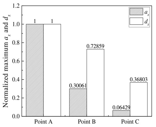
Figure 8.
Comparisons of normalized maximum az and dz at different points.
On the other hand, Figure 9 presents the changes in az and dz with ground depth (Path 4). Similarly, both az and dz show a clear reduction trend along the ground depth, and the decrease rate of az is greater than that of dz. When comparing the az and dz from the track surface into the ground, the az and dz are reduced to 10% at a ground depth of 7.51 m and 23.55 m, respectively. These indicate that the vibration of the ballastless track structure caused by train load has a wide range of influence through the ground depth, which should be considered in the future structural design of high-speed railways.
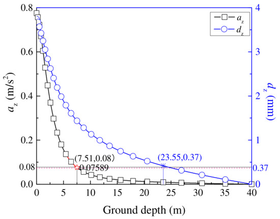
Figure 9.
Variations of az and dz with ground depth.
3.2. Effect of Train Speed
To evaluate the effect of train speed on the dynamic responses of the railway structure, three different train speeds were analyzed in this study; that is v = 56 m/s (200 km/h), v = 83 m/s (300 km/h), and v = 112 m/s (400 km/h). Figure 10 represents the cloud images for the az and dz at different train speeds. As shown here, the maximum vertical displacement occurs near the middle of the front and rear wheels of the two carriages, which indicates that this numerical model can consider the superimposition effect of the dynamic load from different wheels of the train. In addition, Figure 11 shows the variations of az and dz with train speeds in different paths. From these figures, it can be seen that both az and dz increase remarkably with the increase of the train speed, regardless of the monitoring paths. In addition, due to the effects of velocity and damping, the asymmetry of az and dz is more obvious, which is reflected by the wavelength and amplitude of the displacement in front of the load action point being less than those behind the load. These indicate that the train speed impacts the dynamic response of the whole railway structure.
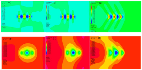
Figure 10.
Comparisons of az and dz at different train speeds. (a) az, E2, v = 56 m/s; (b) dz, E2, v = 56 m/s; (c) az, E2, v = 83 m/s; (d) dz, E2, v = 83 m/s; (e) az, E2, v = 112 m/s; (f) dz, E2, v = 112 m/s.
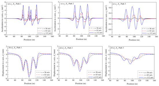
Figure 11.
Comparisons of az, dz with different speeds in different paths: (a) az in Path 1; (b) dz in Path 1; (c) az in Path 2; (d) dz in Path 2; (e) az in Path 3; (f) dz in Path 3.
To further analyze the effect of train speed on az and dz, Figure 12 presents the variations of the normalized maximum az and dz with train speed in different paths. Here, the az and dz at v = 83 m/s in Path 1 are standard values, and other values can be calculated from the ratio of the actual value to the standard value. As illustrated in Figure 12a, the normalized maximum az increases remarkably with increasing train speed, although it reduces rapidly with an increase of depth (Path 2 and Path 3). In addition, the normalized maximum dz increases linearly with the increase of train speed. However, its attenuation trend with depth is not remarkable compared to the normalized maximum az. This indicates that an increment of the train speed significantly enhances the vibration response of a railway structure within the shear wave velocity of soft soil. The influence of train speed should be emphasized in the railway structure design of high-speed railways.
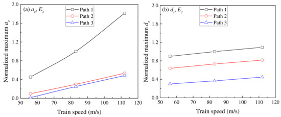
Figure 12.
Variations of normalized maximum az and dz with train speed in different paths: (a) az; (b) dz.
Figure 13 illustrates the variations of az, dz, and σz with ground depth in Path 4. For the selected period data shown in Figure 13a, the az increases with the train speed and decreases rapidly with increased ground depth (Path 4). It is noted that both positive and negative az occurred at the train speed of 112 m/s. This indicates an increase of train speed boosts the vibration of the ground soil. In addition, in Figure 13b, dz increases gradually in the wake of an increased train speed, while the decreasing trend of dz along with depth at a high train speed is faster than that at a low train speed. More importantly, when comparing the σz in Path 4, as illustrated in Figure 13c, the σz near the ground surface is larger at higher train speeds. However, with an increase of depth, σz has a more rapid attenuation trend, which causes the value of σz at a high train speed to be less than that at a low train speed, after a certain depth. These points indicate that the vertical displacement and stress in a specific range of subgrade increase as the train speed increases. However, with an increase of depth, the attenuation trends of vertical displacement and vertical stress under the high-speed conditions become faster, and the affected area gradually decreases.
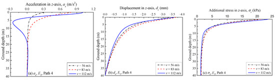
Figure 13.
Variations of az, dz, and σz with ground depth at different speeds in Path 4: (a) az; (b) dz; (c) σz.
3.3. Effect of Embankment Stiffness
In this section, three different stiffnesses of embankment (E1, E2, and E3) were chosen, to evaluate the effect of embankment stiffness on the dynamic response of railway structures, as shown in Figure 14. Figure 15 shows a comparison of az and dz with the embankment stiffness in different paths. As shown in these figures, both az and dz decrease with an increase of embankment stiffness, regardless of the monitoring paths. When comparing the changes of az and dz under different paths, the values of az and dz in Path 1 decrease significantly with an increase of embankment stiffness, followed by Path 2 and Path 3. This indicates that properly strengthening the embankment stiffness can reduce the influence of the train load on railway structure vibration.
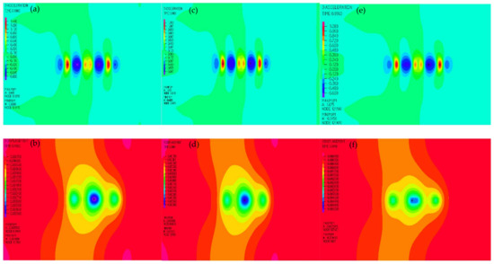
Figure 14.
Comparisons of az and dz cloud with different embankment stiffnesses: (a) az, E1, v = 83 m/s; (b) dz, E1, v = 83 m/s; (c) az, E2, v = 83 m/s; (d) dz, E2, v = 83 m/s; (e) az, E3, v = 83 m/s; (f) dz, E3, v = 83 m/s.
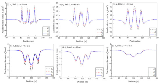
Figure 15.
Changes in az and dz with the embankment stiffness in different paths: (a) az in Path 1; (b) dz in Path 1; (c) az in Path 2; (d) dz in Path 2; (e) az in Path 3; (f) dz in Path 3.
For a more straightforward presentation, Figure 16 shows changes in the normalized maximum az and dz with the normalized embankment stiffness in different paths. Here, az and dz at E2 in Path 1 are standard values, and the other values can be calculated using the ratio of the actual value to the standard value. It can be seen that the normalized maximum az and dz decrease with an increase of the normalized embankment stiffness, irrespective of the monitoring paths. However, with an increase of embankment stiffness, the beneficial effect of strengthening the embankment stiffness on reducing az and dz is weakened, especially in Path 3. This indicates that an increase in embankment stiffness in a specific range can reduce the dynamic response of a railway structure. However, the influence of embankment stiffness on the dynamic response is not as significant as the train speed, as shown in Figure 11.
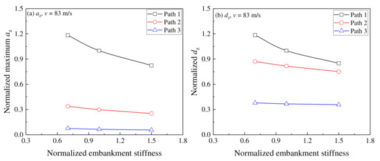
Figure 16.
Relationship between normalized maximum az, dz and normalized embankment stiffness in different paths: (a) normalized maximum az; (b) normalized maximum dz.
For the underlying ground, Figure 17 shows the changes in az, dz, and σz with ground depth with different embankment stiffnesses in Path 4. As shown in Figure 17a, the az decreases with an increase of embankment stiffness, with a rapidly decreasing trend with the ground depth. For dz, as shown in Figure 17b, the dz shows a decreasing trend at higher embankment stiffnesses, although the reduction trend of dz with the ground depth is not as rapid as that of az. More importantly, when considering the effect of embankment stiffness on σz in a railway ground (Figure 17c), similarly to the values of az and dz, the σz decreases with increasing embankment stiffness, irrespective of the ground depth. These factors indicate that increasing the embankment stiffness can slightly lessen the ground vibration, although the effect of embankment stiffness on the ground vibration is not significant.
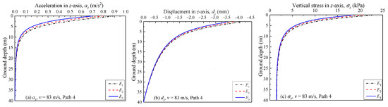
Figure 17.
Variations of az, dz, and σz with depth under different embankment stiffnesses in Path 4: (a) az; (b) dz; (c) σz.
3.4. Comparison of Vertical Stress with Different Methods
The vertical stress caused by a train load decreases gradually with the increase of soil depth in the process of the transfer from the track surface to the ground. At a certain soil depth, the additional stress caused by a train load can be ignored compared with the self-weight of soil. Figure 18 demonstrates the vertical stress on the ground with different train speeds and embankment stiffnesses obtained from SSM and TDM. As shown in Figure 18a, the vertical stress on the ground soil shows an increasing trend with the increase of train speed, especially within a 10 m depth. Moreover, attenuation trends of vertical stress are calculated differently by SSM and TDM. Specifically, the vertical stress in the ground calculated by TDM is less than that calculated by SSM under a low speed condition. When the train speed is relatively high (i.e., v = 112 m/s), the vertical stress on the soil calculated by TDM within 5 m below the ground surface is greater than that calculated by SSM, although the former is smaller than the latter when the ground depth exceeds 5 m. This seems to indicate that under high-speed conditions, this method may underestimate the vertical stress of soil at a certain ground depth caused by a train moving load. However, due to the influence of the short time of the moving load on the vibration energy transfer to an increased depth, the soil vertical stress calculated by the proposed model decays more rapidly with depth. Moreover, in Figure 18b, when the embankment stiffness increases, the vertical stress in the railway ground soil obtained by the two methods decreases slightly. More importantly, the vertical stress obtained by SSM is larger than that obtained with TDM, regardless of the embankment stiffness. This shows that when the vehicle speed is not high (i.e., v = 83 m/s), the proposed method underestimates the stress level under different embankment stiffnesses. The above findings imply that, while the vertical stress in the railway ground soil has a noticeable growth trend with an increase of train speed, it is hardly affected by changing the embankment stiffness. It should be noted that for a lower velocity and greater soil depth, the vertical stress obtained by SSM is significantly greater than that obtained by TDM, which means that the proposed model may be limited in applications under these conditions.
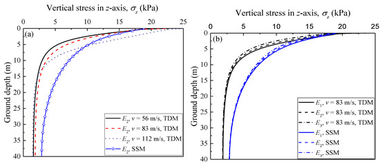
Figure 18.
Relationship between vertical stress and ground depth with different train speeds and embankment stiffnesses: (a) train speed; (b) embankment stiffness.
4. Conclusions
It is important to study the vibration of a track formation caused by a moving train load, for the dynamic stability and vibration control of a railway structure. In this study, numerical simulation based on TDM was adopted to evaluate the dynamic response of the railway formation of a high-speed railway. The main conclusions include the following aspects:
- The dynamic acceleration and displacement in the vertical direction in railway structures are mainly generated under a moving train load, which should be considered in the railway structural design. Moreover, with increasing train speeds, the soil vibration along the direction of train movement appears to experience a significant fluctuation effect, which is manifested in the peak value of the vertical displacement of the track lagging behind the position of the wheel load, while the vertical displacement of the track at the rear of the wheel load is not equal to that at the front of the wheel load. The maximum vertical displacement occurs near the middle of the front and rear wheels of the two carriages, which indicates that the numerical model can consider the superimposition effect of the dynamic load from different wheels of the train.
- The vertical displacement and vertical stress in a high-speed railway structure increase as the train speed increases. However, with the increased depth of ground, the attenuation trends of the vertical displacement and vertical stress under a high-speed train load condition become faster. Thus, the influenced area becomes smaller.
- Since the embankment stiffness of a ballastless track structure is much greater than the subsoil stiffness, the increase of embankment stiffness has little effect on the vertical stress transferred from the track to the ground soil, which indicates that for a ballastless track structure, the enhancement of the stiffness of the sub-structure cannot effectively reduce the propagation of dynamic stress with soil depth. In code design, it is essential to increase the stiffness of the upper and lower soil layers in the same proportion. In particular, when the railway foundation contains a soft soil with low stiffness, the improvement of the stiffness of the soft soil should be emphasized.
- When the train speed is low, the vertical stress in the ground soil obtained from TDM is less than that calculated using SSM. When the train speed is high, the vertical stress of the soil calculated by TDM within 5 m below the ground surface is greater than that calculated by SSM, although the former is smaller than the latter when the ground depth exceeds 5 m. This indicates that this design code may underestimate dynamic stresses on the railway formation in high-speed situations (i.e., v = 112 m/s). However, for lower velocities and greater soil depths, the vertical stress obtained by SSM is significantly greater than that obtained by TDM, and the proposed model may be limited in application under these conditions.
It should be emphasized that the method presented in this paper can effectively calculate the influence of train speed on the dynamic response of a railway structure. Compared with the SSM (vehicle load is equivalent to soil column) for this specification, the results of the TDM were more consistent with the stress transfer process of the soil in the process of train movement, and more accurate results can be obtained. Especially for high-speed trains, the dynamic stress of the soil shows a fluctuation effect, and the transient dynamic method is more practical. However, when simulating a train load, the calculation method in this paper does not consider the influence of track irregularities and vibration frequency on the vibration characteristics of the railway structure, which needs to be further considered in future research.
Author Contributions
Conceptualization, J.Y.; methodology, J.Y., Y.Z. and P.M.; software, Y.Z.; validation, J.Y., Y.Z. and P.M.; formal analysis, Y.Z.; investigation, P.M.; resources, Y.Z. and P.M.; data curation, Y.Z.; writing—original draft preparation, J.Y.; writing—review and editing, J.Y., Y.Z. and P.M.; visualization, Y.Z. and P.M.; supervision, J.Y.; project administration, J.Y.; funding acquisition, J.Y. All authors have read and agreed to the published version of the manuscript.
Funding
This research was funded by the Fundamental Research Funds for the Central Universities (Grant No. JZ2022HGQA0160).
Institutional Review Board Statement
Not applicable.
Informed Consent Statement
Not applicable.
Data Availability Statement
Not applicable.
Conflicts of Interest
The authors declare no conflict of interest.
References
- Kaynia, A.M.; Madshus, C.; Zackrisson, P. Ground vibration from high-speed trains: Prediction and countermeasure. J. Geotech. Geoenviron. Eng. 2000, 126, 531–537. [Google Scholar] [CrossRef]
- Takemiya, H. Field vibration mitigation by honeycomb WIB for pile foundations of a high-speed train viaduct. Soil Dyn. Earthq. Eng. 2004, 24, 69–87. [Google Scholar] [CrossRef]
- Zhan, Y.X.; Yao, H.L.; Lu, Z.; Yu, D.M. Dynamic analysis of slab track on multi-layered transversely isotropic saturated soils subjected to train loads. Earthq. Eng. Eng. Vib. 2004, 13, 731–740. [Google Scholar] [CrossRef]
- Ai, Z.Y.; Xu, C.J.; Ren, G.P. Vibration of a pre-stressed plate on a transversely isotropic multilayered half-plane due to a moving load. Appl. Math. Model. 2018, 59, 728–738. [Google Scholar] [CrossRef]
- Bian, X.C.; Jiang, H.G.; Chang, C.; Hu, J.; Chen, Y.M. Track and ground vibrations generated by high-speed train running on ballastless railway with excitation of vertical track irregularities. Soil Dyn. Earthq. Eng. 2015, 76, 29–43. [Google Scholar] [CrossRef]
- Edmond, V.M.; Niki, D.B. Dynamic response of an isotropic elastic half-plane with shear modulus varying with depth to a load moving on its surface. Transp. Geotech. 2019, 20, 100248. [Google Scholar] [CrossRef]
- Huang, H.H.; Yang, Y.B.; Chang, D.W. Wave barriers for reduction of train-induced vibrations in soils. J. Geotech. Geoenviron. Eng. 2004, 130, 1283–1291. [Google Scholar] [CrossRef]
- Yang, Y.B.; Hung, H.H.; Chang, D.W. Train-induced wave propagation in layered soils using finite/infinite element simulation. Soil Dyn. Earthq. Eng. 2003, 23, 263–278. [Google Scholar] [CrossRef]
- Yuan, Z.H.; Boström, A.; Cai, Y.Q.; Pan, X.D.; Cao, Z.G.; Shi, L. The wave function method for calculation of vibrations from a twin tunnel in a multi-layered half-space. Soil Dyn. Earthq. Eng. 2019, 125, 105716. [Google Scholar] [CrossRef]
- Fu, Q.; Gu, M.X.; Yuan, J.; Lin, Y.F. Experimental study on vibration velocity of piled raft supported embankment and foundation for ballastless high speed railway. Buildings 2022, 12, 1982. [Google Scholar] [CrossRef]
- Sheng, X.; Jones, C.J.C.; Petyt, M. Ground vibration generated by a harmonic load acting on a railway track. J. Sound Vib. 1999, 225, 3–28. [Google Scholar] [CrossRef]
- Bian, X.C.; Chen, Y.M. An explicit time domain solution for ground stratum response to harmonic moving load. Acta Mech. Sin. 2006, 22, 469–478. [Google Scholar] [CrossRef]
- Bian, X.C.; Chen, Y.M.; Hu, T. Numerical simulation of high-speed train induced ground vibrations using 2.5 D finite element approach. Sci. China Ser. G Phys. Mech. Astron. 2018, 51, 632–650. [Google Scholar] [CrossRef]
- Galvín, P.; Romero, A.; Domínguez, J. Fully three-dimensional analysis of high-speed train-track-soil-structure dynamic interaction. J. Sound Vib. 2010, 329, 5147–5163. [Google Scholar] [CrossRef]
- Huang, H.H.; Chen, G.H.; Yang, Y.B. Effect of railway roughness on soil vibrations due to moving trains by 2.5 D finite/infinite element approach. Eng. Struct. 2013, 57, 254–266. [Google Scholar] [CrossRef]
- He, C.; Zhou, S.; Guo, P.; Di, H.; Zhang, X. Modelling of ground vibration from tunnels in a poroelastic half-space using a 2.5-D FE-BE formulation. Tunn. Undergr. Space Technol. 2018, 82, 211–221. [Google Scholar] [CrossRef]
- Ju, S.H. Three-dimensional analyses of wave barriers for reduction of train-induced vibrations. J. Geotech. Geoenviron. Eng. 2004, 130, 740–748. [Google Scholar] [CrossRef]
- Lombaert, G.; Degrande, G. Ground-borne vibration due to static and dynamic axle loads of InterCity and high-speed trains. J. Sound Vib. 2009, 319, 1036–1066. [Google Scholar] [CrossRef]
- Yang, Y.B.; Hung, H.H. Soil vibrations caused by underground moving trains. J. Geotech. Geoenviron. Eng. 2008, 134, 1633–1644. [Google Scholar] [CrossRef]
- Cai, Y.Q.; Cao, Z.G.; Sun, H.L.; Xu, C.J. Dynamic response of pavements on poroelastic half-space soil medium to a moving traffic load. Comput. Geotech. 2008, 36, 52–60. [Google Scholar] [CrossRef]
- Cai, Y.Q.; Cao, Z.G.; Sun, H.L.; Xu, C.J. Effects of the dynamic wheel-rail interaction on the ground vibration generated by a moving train. Int. J. Solids Struct. 2010, 47, 2246–2259. [Google Scholar] [CrossRef]
- Takemiya, H.; Bian, X. Substructure simulation of inhomogeneous track and layered ground dynamic interaction under train passage. J. Eng. Mech. 2005, 131, 699–711. [Google Scholar] [CrossRef]
- Auersch, L. Dynamic stiffness of foundations on inhomogeneous soils for a realistic prediction of vertical building resonance. J. Geotech. Geoenviron. Eng. 2008, 134, 328–340. [Google Scholar] [CrossRef]
- Bian, X.; Jiang, H.; Chen, Y.; Chang, C. Dynamic responses generated by high-speed train running on ballastless slab track with excitation of vertical track irregularity. Soil Dyn. Earthq. Eng. 2015, 76, 29–43. [Google Scholar] [CrossRef]
- Zhang, H.; Li, L.; Ma, W.; Luo, Y.; Li, Z.; Kuai, H. Effects of welding residual stresses on fatigue reliability assessment of a PC beam bridge with corrugated steel webs under dynamic vehicle loading. Structures 2022, 45, 1561–1572. [Google Scholar] [CrossRef]
- TB 10621; Code for Design of High-Speed Railway. State Railway Administration of China: Beijing, China, 2014. (In Chinese)
- Zeng, E.X. Long-Term Settlement of Soft Soil Ground Induced by Traffic Loadings; Zhejiang University: Hangzhou, China, 2008. (In Chinese) [Google Scholar]


Publisher’s Note: MDPI stays neutral with regard to jurisdictional claims in published maps and institutional affiliations. |
© 2022 by the authors. Licensee MDPI, Basel, Switzerland. This article is an open access article distributed under the terms and conditions of the Creative Commons Attribution (CC BY) license (https://creativecommons.org/licenses/by/4.0/).