Article

Analytical and Numerical Solutions to Static Analysis of Moderately Thick Cross-Ply Plates and Shells

Department of Mechanical Engineering, Gebze Technical University, Gebze 41400, Turkey
*
Author to whom correspondence should be addressed.
Appl. Sci. 2022, 12(24), 12547; https://doi.org/10.3390/app122412547
Submission received: 7 November 2022 / Revised: 21 November 2022 / Accepted: 28 November 2022 / Published: 7 December 2022
(This article belongs to the Section Materials Science and Engineering)

Abstract

:
This study aimed to provide a static solution to the boundary value problem presented by symmetric (0°/90°/0°) and antisymmetric (0°/90°) cross-ply composite, moderately thick shallow shells and plates (a special case of the shells) subjected to mixed-type unsolved boundary conditions. The boundary-discontinuous double Fourier series (BDM) method, in which displacements are expressed in trigonometric functions, is employed in a well-established framework. The analytical solution obtained using the BDM is compared with the successful integration of the generalized differential quadrature (GDQ) method for the static analysis of composite shells with a roller skate-type boundary condition prescribed on two opposite edges, while the remaining two edges are subjected to simply supported constraints. Comprehensive results are presented in order to show the effects of curvature on the deflections and stresses of moderately thick shallow shells made up of symmetric and antisymmetric cross-ply laminated composite materials. The validity of the proposed model is authenticated through the available HSDT-based literature review, and the convergence characteristics are demonstrated. The changing trends of displacements and stresses are explained in detail by investigating the effect of various parameters such as lamination, material properties, the effect of curvature, etc. Based on the results obtained using the proposed static solution, analytical BDM results were found to be in very close agreement with the numerical GDQ method, especially for symmetric lamination. However, the results obtained using the BDM and GDQ methods for antisymmetric lamination show differences, possibly due to the presence of a discontinuity in the derivatives originating from the bending–stretching matrix in antisymmetric lamination. Important numerical results presented include the sensitivity of the predicted response quantities of interest to material properties, lamination, and thickness effects, as well as their interactions. The results presented here may also serve as benchmark comparison points with numerical solutions such as finite elements, boundary elements, etc.

1. Introduction

Laminated composite materials are increasingly preferred in major industries such as aerospace, naval, and construction due to their high strength-to-weight and stiffness-to-weight ratios (reducing fuel consumption), and, more importantly, their ability to be tailored to achieve optimal design through manipulation of the composition of composite materials, stacking ply orientation, etc. Over the years, the mechanical behavior of laminated composites such as glass/epoxy, graphite/epoxy, boron/epoxy, Kevlar-49/epoxy, etc., has been researched by many scientists. However, the anisotropic behavior and bending–stretching coupling of composite materials and the need to satisfy distinct boundary conditions create additional problems for the analysis of those structures.
Over the years, several well-known shell theories with many assumptions have been established in order to investigate the static behavior of plate and shell structures, such as those provided by Love [1], Donnell [2], Sanders [3], Timoshenko [4], and Reissner [5]. A literature review including refined theories of laminated composite plates and shells is given in [6,7,8,9,10,11]. Many approximate numerical techniques and analytical methods have been employed in the literature to analyze the static behavior of composite shells. The Levy method has been the most popular analytical method for the analysis of two edges fixed by simply supported laminated plates and shells, and it is able to analyze cross-ply and antisymmetric angle-ply laminates. Such solutions are based on the well-known method of separation of variables. A view of the comprehensive study on the boundary value problems of laminated plates and shells using analytical methods can be found in the following studies. Pagano [12] constructed three-dimensional elasticity solutions for cross-ply rectangular plates for simply supported boundary conditions. Srinivas and Rao (1970) presented an elasticity solution for the static and dynamic analysis of cross-ply composite plates with Navier-type boundary conditions. Fan and Zhang [13] introduced a similar procedure, using an elasticity solution on doubly curved cross-ply shells with simply supported boundary conditions. In a recent overview, various three dimensional (3D) analytical approaches have been introduced for resolving multilayered panels with arbitrary boundary conditions. Kumari and Kar [14] improved an analytical three-dimensional elasticity solution based on a multi-term EKM along with a mixed formulation for the static bending of single- and multi-layer composite thick, moderately thick, and thin cylindrical shell panels. The proposed technique can yield accurate results with better computational efficiency using just one or two terms and two or three iteration steps in comparison to 3D FE for arbitrary boundary conditions (SS, CS, CF). Atashipour et al. [15] presented exact 3-D Levy-type solutions for the static analysis of thick composite plates based on 3-D elasticity and various shear deformation theories with different types of classical boundary conditions, namely simply supported, clamped, and free edge. Nik and Tahani [16] analyzed the bending of rectangular laminated plates with arbitrary lamination and various combinations of simply supported, clamped, and free-type boundary conditions by employing the Extended Kantorovich method. Analytical solutions may fail to carry out complex analyses such as those of surface-parallel orthotropy/anisotropy, lamination asymmetry, and curvature effect (leading to bending, stretching, and coupling), which usually involve the use of laminated composite shell equations. Therefore, a different methodology should be proposed to enable effective solutions. Methodologies integrating the Fourier series have great potential to solve the problems encountered in conventional analytical solutions. The following studies include these Fourier series-based methodologies.
Whitney and Leissa [17] obtained an exact solution based on the Fourier series as displacement functions for the static, frequency, and buckling analysis of antisymmetric cross-ply and angle-ply laminated plates for different boundary conditions. Reddy and Liu [18] presented an extension of Sanders’s shell theory for laminated doubly curved, symmetric, and antisymmetric cross-ply shells with simply support boundary conditions under sinusoidal, uniform, and point load. Static and natural frequency analysis was achieved with an exact solution, imparting Fourier series to the displacement fields. Huang and Yuan [19] presented a general analytical solution for the static bending problem posed by an anisotropic plate with arbitrary boundary conditions and loading. The numerical results were given only for simply supported-type boundary conditions. Li et al. [20] presented an accurate solution method for the static and vibration analysis of a functionally graded composite plate with general boundary conditions considering the improved Fourier series method. The characteristic equations are easily obtained by substituting admissible displacement functions into the governing equations and general elastic boundary equations. Chaudhuri [21,22] presented an analytical method called the boundary discontinuous double Fourier series approach as a solution to the boundary value problems, satisfying Dirichlet, Neumann, and mixed admissible boundary conditions. According to the proposed method, a cross-ply panel should be solved with only a single set of Fourier series corresponding to each displacement and rotation component. Certain boundary conditions which result in discontinuities in the solution were improved by proposing additional coefficients, so-called the boundary Fourier coefficients. The state of the art for mathematical modeling and solution techniques employed in the analysis of composite shells was discussed in Chaudhuri and Kabir [23], Chaudhuri and Kabir [24,25], Chaudhuri and Abu-Arja [26,27], Oktem and Chaudhuri [28,29,30,31], Mantari et al. [32], and Oktem and Soares [33] for various types of boundary conditions. Investigation of deformation, stresses, and different coupling effects for internally pressurized composite cylinders by considering the mixed type of boundary conditions were presented by [21,34]. Furthermore, the term “roller skate” has been introduced previously in these articles, but the solution for this boundary condition was not provided.
Apart from conventional computational algorithms using the weighted residual method, the mentioned techniques strongly depend on the way field variables are described within the bounds of the computational domain. For instance, generalized differential quadrature (GDQ) has been proven to be an effective and precise technique for numerically assessing higher-order differential equations, particularly when employed for structural analysis. Extensive successful integration of GDQ was carried out in the following articles in order to explore statistics and dynamics of curved structures. Viola et al. [35] investigated the static analysis of doubly curved composite shells using a 2D HSDT. The numerical problems were solved using the GDQ technique. Asadi and Qatu [36] carried out the static analysis of relatively deep, thick composite doubly curved shells using FSDT. Cross-ply, angle-ply, and general lay-up cylindrical shells with six discrete boundary conditions were examined with using GDQ. Kurtaran [37,38] presented a series of geometrically nonlinear transient analyses of moderately thick laminated composite shallow shells, thick and deep laminated composite curved beams, and moderately thick deep functionally graded curved beams with constant curvature, respectively, using the generalized differential quadrature method. It has been demonstrated that a non-uniform grid should be selected. The local form of GDQ has been shown to offer highly accurate results by reducing the number of points used in the solution [39]. Computational grid selection plays a vital role in the easy implementation of boundary conditions, which impacts the structure’s global response [40]. Several works concerning plate and shell structure solutions using the GDQ method can be found in [41,42,43,44]. Since the boundary conditions can easily be adapted and accurate results could be obtained with this technique, this study aims to compare analytical solutions with the numerical method, GDQ.
The provided literature review showed that there is still a gap in the static analysis of moderately thick, cross-ply composite plates and shells with roller skate boundary conditions. The available FSDT- or HSDT-based solutions for cross-ply curved panels are primarily focused on simply supported and clamped boundary conditions. Roller skate-type boundary conditions are of great importance, as they may be encountered in modeling many structures, especially in civil engineering. As stated, a solution for this boundary condition has not been provided in the literature to the best of the authors’ knowledge. Thus, the primary objective of the present study is to provide analytical solutions by applying boundary-discontinuous Fourier analysis to the deformation of symmetric (0°/90°/0°) and antisymmetric (0°/90°) cross-ply composite shells with roller skate-type boundary conditions prescribed on two opposite edges, while the remaining two edges are subjected to simply supported constraints. The virtual work principle and the first-order shear deformation theory are used to obtain the governing equilibrium equations. Partial derivatives in the equilibrium equations are expressed and solved using an analytical or strong-form solution, the so-called boundary discontinuous Fourier series method, and with the numerical method, GDQ. It is also important to study the sensitivity of the predicted response quantities of interest to lamination, material property, thickness, and curvature effects as well as their interactions as a second objective. Numerical results using both methods are compared with the available results in the literature and those obtained using the finite element commercial program ANSYS.

2. Statement of the Problem

A model of the schematic plot and geometric parameters of a curved shallow shell based on an orthogonal curvilinear coordinate (ξ1, ξ2, ξ3 = ξ) system is shown in Figure 1. The orthogonal coordinates (ξ1, ξ2, ξ) are placed on the curved shell mid-surface, ξ3 = ξ = 0, and the ζ coordinate coincides with the vertical direction to the mid-surface. The curved shell has a principal curvature denoted as R1 and R2 located on the middle surface (ξ = 0). The shell is made up of N, a finite number, of perfectly bonded layers with uniform thickness. The diverse geometries of the shell are obtained by adjusting the radius of curvature and designating a cylindrical shell (R1 = R, R2 = ∞ or R1 = ∞, R2 = R), spherical (R1 = R, R2 = R), and plate (R1 = ∞, R2 = ∞). In this study, the analysis used is a linear static analysis. It is also assumed that there is no penetration and no delamination between the layers and that they are perfectly bonded.
The displacement field addressing first order shear deformation theory may be written as [45]:
u ¯ 1 ξ 1 , ξ 2 , ξ = u 1 ξ 1 , ξ 2 + ξ · θ 1 ξ 1 , ξ 2
u ¯ 2 ξ 1 , ξ 2 , ξ = u 2 ξ 1 , ξ 2 + ξ · θ 2 ξ 1 , ξ 2
u ¯ 3 ξ 1 , ξ 2 , ξ = u 3 ξ 1 , ξ 2
where ui (i = 1,2,3) are the displacement field of a point on the middle-surface of the shell along the ξ1, ξ2, and ξ3 axes. θ 1 and θ 2 are the rotations around the ξ2 and ξ1 axis, respectively. The equivalent single-layer approach based on a first-order shear deformation theory is incorporated into the shell formulation. According to the kinematic relations from the theory of elasticity in curvilinear coordinates, the generalized strain–displacement relations for the doubly curved panels using the displacement fields in Equations (1)–(3) are expressed as below in the case of small elastic deformation:
ε 1 0 = u 1 ξ 1 + u 3 R 1 ,   ε 1 1 = θ 1 ξ 1
ε 2 0 = u 2 ξ 2 + u 3 R 2 ,   ε 2 1 = θ 2 ξ 2
ε 6 0 = u 2 ξ 1 + u 1 ξ 2 + 1 2 1 R 2 1 R 1 u 2 ξ 1 u 1 ξ 2 ,   ε 6 1 = θ 1 ξ 2 + θ 2 ξ 1
ε 4 0 = θ 1 + u 3 ξ 1 u 1 R 1
ε 5 0 = θ 2 + u 3 ξ 2 u 2 R 2
For the sake of brevity, the derivation of the equilibrium equations of the composite doubly curved panel using the virtual work principle is not explained here. Further explanations are given in Reddy [45]. With the use of the virtual work principle, the characteristic equations of the panel, defined by five highly coupled partial differential equations in five unknowns, i.e., three displacements, and two rotations are given as below:
δ u 1 :   N 1 , 1   + N 6 , 2   + Q 2 R 1 c M 6 , 2 = 0
δ u 2 :   N 6 , 1   + N 2 , 2   + Q 1 R 2 + c M 6 , 1 = 0
δ u 3 : Q 1 , 2   + Q 2 , 1 N 1 R 1 N 2 R 2 = q
θ 1 : M 1 , 1 + M 6 , 2   Q 2 = 0
θ 2 :   M 6 , 1 + M 2 , 2 Q 1 = 0
where q is the distributed transverse load and Ni, Mi, Pi (i = 1, 2, 6) denote stress resultants, stress couples (moment resultants), and second stress couples (resultant from the second moment of stress), are as defined by Reddy and Liu [46]. Qi (i = 4, 5), represents the transverse shear stress resultants. The forces and moments are further elaborated upon to show the individual components as follows:
{ N 1 N 2 N 6 M 1 M 2 M 6 } = [ A 11 A 12 A 16 B 11 B 12 B 16 A 21 A 22 A 26 B 21 B 22 B 26 A 61 A 62 A 66 B 61 B 62 B 66 B 11 B 12 B 16 D 11 D 12 D 16 B 21 B 22 B 26 D 21 D 22 D 26 B 61 B 62 B 66 D 61 D 62 D 66 ] { ε 1 0 ε 2 0 ε 6 0 ε 1 1 ε 2 1 ε 6 1 }
Q 1 Q 2 = A 55 A 54 A 45 A 44 ε 4 0 ε 5 0
where A ij , B ij ,   D ij are the laminate rigidities. These are given as follows:
A ij , B ij , D ij = k = 1 N ξ k 1 ξ k Q ij k 1 , ξ , ξ 2 d ξ ,       ( i ,   j = 1 ,   2 ,   6 )
The obtained governing equations are expressed as follows:
K ij δ j = f i i , j = 1 ,   2 ,   3 ,   4 ,   5   and   K ij = K ji
where
{ δ j } T = u 1   u 2   u 3 , θ 1 , θ 2  
{ f j } T = 0   0 q , 0 , 0  
The problem is solved in conjunction with the mixed type of simply supported and roller skate boundary conditions, and they are prescribed at the edges as given below:
Roller Skate:
ξ 1 = 0 a ,         u 1 = u 2 = θ 2 = M 1 = Q 1 = 0
Simply Supported:
ξ 2 = 0 b ,         u 1 = u 3 = θ 1 = M 2 = N 2 = 0
Following section explains the solution procedure for the governing partial differential equations given in Equations (9)–(13) subjected to the above boundary conditions.

3. Solution Methodology

3.1. Boundary Discontinues Fourier Series Method

We proposed a boundary discontinuous Fourier series method as the first proposed analytical solution. The functions expressing a displacement solution to the boundary value problem when mixed-type boundary conditions were included into the mathematical formulation initially. These functions, which are adapted for FSDT-based cross-ply panels, are as follows:
u 1 , θ 1 = m = 0 n = 1 U mn , X mn cos α ξ 1 sin β ξ 2 ,         0 < ξ 1 < a ; 0 < ξ 2 < b
u 2 , θ 2 = m = 1 n = 0 V mn , Y mn sin α ξ 1 cos β ξ 2 ,         0 < ξ 1 < a ; 0 < ξ 2 < b  
u 3 = m = 1 n = 1 W mn sin α ξ 1 sin β ξ 2 ,         0 x 1 a ; 0 x 2 b
The unknown coefficients (Umn, Vmn, Wmn, Xmn, Ymn,) regarding the displacements are represented as 5 mn + 2 m + 2 n. The assumed solution functions in Equations (22)–(24) do not entirely ensure that the prescribed boundary conditions. Thus, whenever the relevant boundary conditions are not satisfied, the assumed solution function or its derivative at the boundaries is forced to satisfy it. The derivatives of the assumed solution functions are achieved by expanding them in a double Fourier series in the form discussed by Hobson [46], Green [47] and Chaudhuri [21,22]. Boundary Fourier coefficients arising from the discontinuities of the assumed functions or their derivatives at the boundaries are handled by utilizing the Lebesgue integration theory. This theory was considered the procedure for the differentiation of these functions. The function u1 given by Equation (22) and its first partial derivative, u 1 , 1 , given by Equation (25) and obtained by term-wise differentiation, are not satisfied at the edges, ξ 1 = 0, a, and thus violate the boundary constraints and complementary boundary constraints, respectively, at these edges. Therefore, u1 is forced to vanish at these edges, while for further differentiation, u 1 , 11 is expanded in a double Fourier series in the form advised by Chaudhuri [21,22], thereby satisfying the complementary boundary constraints (inequality). The partial derivatives are obtained as follows:
u 1 , 1 = m = 1 n = 1 α U m n sin ( α ξ 1 ) sin ( β ξ 2 )
u 1 , 11 = m = 1 1 2 a ¯ n sin ( β ξ 2 ) + m = 1 n = 1 α 2 U m n + γ m a ¯ n + ψ m b ¯ n cos ( α ξ 1 ) sin ( β ξ 2 ) ,
u 1 , 22 = 1 2 n = 1 β 2 U 0 n sin ( β ξ 2 ) m = 1 n = 1 β 2 U m n cos ( α ξ 1 ) sin ( β ξ 2 )
In the same way as u 1 ,   u 3 , 1 is forced to vanish at the edges, ξ 1 = 0 and a. Thus, the derivatives of u 3 , 1 and u 3 , 11 are obtained as shown in Equations (28) and (29) by expanding them in a double Fourier series as previously discussed.
u 3 , 1 = m = 1 1 2 c ¯ n sin ( β ξ 2 ) + m = 1 n = 1 α W m n + γ m c ¯ n + ψ m d ¯ n cos ( α ξ 1 ) sin ( β ξ 2 )
u 3 , 11 = m = 1 n = 1 α α W m n + γ m c ¯ n + ψ m d ¯ n sin ( α ξ 1 ) sin ( β ξ 2 )
in which
γ n , δ n = 0 , 1 , n = odd 1 , 0 , n = even
Other derivatives of the assumed solution functions can be obtained through term-wise differentiation. The details of the proposed method are available in Chaudhuri [21,22]. The above step generates an additional 4 n unknown boundary Fourier coefficients ( a ¯ n , b ¯ n , c ¯ n , d ¯ n ) generated from the differentiation procedure. Boundary Fourier coefficients are defined in Appendix A.
The substitution of the assumed displacement functions and their appropriately obtained derivatives into the governing PDE’s yields 5 mn + 2 m + 2 n linear algebraic equations for equating the coefficients of cos ( α ξ 1 ) sin ( β ξ 2 ) , sin(β ξ 2 ), sin(α ξ 1 ), etc., as shown below:
m = 1 n = 1 cos ( α ξ 1 ) sin ( β ξ 2 ) { A 11 α 2 A 66 β 2 f 1 + f 2 β 2 U m n                 + f 2 A 12 α β A 66 α β V m n + g 1 α + f 1 α W m n }                 + B 11 α 2 + f 1 f 2 β 2 c X m n + c D 66 α β Y m n + A 11 b n + g 1 + f 1 d n                 = 0
m = 1 n = 1 sin ( α ξ 1 ) cos ( β ξ 2 ) { f 2 α β A 12 α β A 66 α β U m n         + A 66 α 2 A 22 β 2 f 5 + f 2 α 2 V m n + f 6 W m n + c D 66 α β X m n         + f 7 Y m n } = 0
m = 1 n = 1 sin ( α ξ 1 ) sin ( β ξ 2 ) { f 3 α U m n + f 6 V m n + f 8 f 9 R y f 10 W m n + f 11 X m n + f 12 Y m n A 55 α b n } = m = 1 n = 1 q m n sin ( α ξ 1 ) sin ( β ξ 2 )
m = 1 n = 1 cos ( α ξ 1 ) sin ( β ξ 2 ) { B 11 α 2 + c D 66 β 2 + f 1 U m n + f 2 α β c V m n                                                         + f 13 α A 55 α W m n } + g 2 X m n + D 12 α β D 66 α β Y m n + B 11 b n                                                         + f 13 A 55 d n = 0
m = 1 n = 1 sin ( α ξ 1 ) cos ( β ξ 2 ) { c D 66 α β U m n + c D 66 α 2 B 22 β 2 + f 5 R y V m n + ( f 14 β A 44 β ) W m n + D 12 α β D 66 α β X m n + f 15 Y m n } = 0
n = 1 sin ( β ξ 2 ) U 0 n f 4 + A 11 2 a n + f 3 2 c n c D 66 β 2 2 X 0 n = 0
n = 1 sin ( β ξ 2 ) c D 66 β 2 2 U 0 n D 66 β 2 2 X 0 n + A 55 2 + B 11 2 R x c n + B 11 2 a n = 0
m = 1 sin ( α ξ 1 ) V m 0 D 66 c 2 A 66 + c D 66 Y m 0 = 0
m = 1 sin ( α ξ 1 ) V m 0 c D 66 D 66 Y m 0 = 0
The constants of Equations (31)–(39) can be found in Appendix B. The remaining equations are supplied by the geometric and boundary conditions given in Equation (20). u 1 and Q 1 are forced to vanish at the edges, ξ 1 = 0 and a. Satisfying these geometric boundary conditions generates an additional 4 n linear algebraic equations.
For all values of n = 1 , 2 ,
m = 1 , 3 , 5 , δ m U m n = 0 ,   U 0 n + m = 2 , 4 , 6 , γ m U m n = 0 ,
m = 1 sin ( α ξ 1 ) A 55 α W m n + X m n U m n R x H ¯ = 0 ,
in which, at the boundaries ξ 1 = 0 and a, H ¯ = 1 and H ¯ = ( 1 ) m in Equation (41), respectively.
Finally, the above operations result in, in total, 5 mn + 2 m + 6 n linear algebraic equations with as many unknowns and supply a complete solution to the boundary value problem considered here. The unknown Fourier coefficients (Umn, Vmn, Wmn, Xmn, Ymn, U0n, Vm0, X0n, and Ym0) in Equations (31)–(39) are solved in terms of boundary Fourier coefficients ( a ¯ n , b ¯ n , c ¯ n , and d ¯ n ) in the interest of computational efficiency. These are, consequently, substituted into the boundary equations given in Equations (40) and (41). This step reduces the size of the solution matrix from (5 mn + 2 m + 6 n) × (5 mn + 2 m + 6 n) to (4 n) × (4 n), which is solved using the MATLAB code developed for this solution.

3.2. Generalized Differantial Quadrature Method

In this study, the GDQ method introduced by Shu [48] which is the improved form of DQM, is used to convert the partial derivatives of the field variables in equilibrium equations as well as boundary conditions at the grid points into algebraic equations. Before the application of GDQ, the laminated shell is discretized with grid points in order to apply the equilibrium equations and boundary conditions. Gauss–Lobatto points, which increase the accuracy of derivatives in the GDQ method [39], are selected as the grid points for the solution. The Gauss–Lobatto points formulized in Equations (42) and (43) are distributed more extensively at edge points, and they create grid points on the boundaries.
x i = a 2 ( 1 cos i 1 π M 1 ,       i = 1 , 2 , ,   n x + 1
y j = b 2 ( 1 cos j 1 π N 1 ,       j = 1 , 2 , ,   n y + 1
In the GDQ method, the derivative of a solution function with respect to a variable at a given discrete point can be calculated as a weighted linear sum of the function values at all discrete points in the mesh line. The stability and accuracy of the proposed numerical method is highly affected by the calculation of the weight coefficients, location, and count of grid points [40]. According to the GDQ method, the r-th or s-th-order derivative of a function f at x and y or both directions with nx and ny discrete grid points can be computed by:
f r x i , y j x r = k = 1 n x C i k r f ( x k , y j ) ,   r = 1 , 2 , ,   n x 1  
f s x i , y j y s = m = 1 n y C j m r f ( x i , y m ) ,   s = 1 , 2 , ,   n y 1
f r + s x i , y j x r y s = k = 1 n x C i k r m = 1 n y C j m s f ( x k , y m ) ,       r = 1 , 2 , ,   n x 1 ,   s = 1 , 2 , ,   n y 1
f(x,y) and C i j r are the function values and the weight coefficients for the r-th order derivatives at (xi, yj) grid point. Lagrange polynomial functions are chosen to determine the weight coefficients C i j r . Weight coefficients for the first-order derivative, i.e., r = 1, can be written as
C i k 1 = ϕ x i x i x j ϕ x j ,   i ,   j = 1 ,   2 , ,   n x   and   i j
where
C i k 1 = ϕ x i x i x j ϕ x j ,   i ,   j = 1 ,   2 , ,   n x   and   i j
Recursive relations for higher-order derivatives can be written as
C i j r = r C i i r 1 C i j 1 C i j r 1 x i x j ,     i j  
C i i r = j = 1 ,   i j   n x C i j r
Following the procedure as explained above, the governing equilibrium equations subjected to mixed-type simply supported and roller skate boundary conditions are written in terms of the function values at the grid points. All of the algebraic equation system can be expressed simply in the matrix form as
K U = F    
The total number of unknown coefficients in terms of unknown displacement values is 5(nx + 1) (ny + 1). The number of equations written for the governing equilibrium equations at the internal grid points is 5(nx − 1) (ny − 1). The number of equations written for the boundary conditions given in Equations (20) and (21) is 10(nx + 1) + 10(ny − 1). The total number of equations is equal to the total number of unknown coefficients. Equation (51) is subsequently solved in order to find unknown displacement values.

4. Numerical Results and Discussion

In this section, the static analysis of symmetric ([0°/90°/0°] and [0°/90°/90°/0°]) and antisymmetric ([0°/90°]) laminated cross-ply spherical (R1 = R2 = R), cylindrical (either R1 = ∞ or R2 = ∞), and flat panels (R1 = R2 = ∞) subjected to simply supported boundary conditions prescribed on two opposite edges and roller skate-type boundary conditions on the remaining two edges is investigated. A computer program for that purpose was written in the MATLAB program in order to implement both proposed solution methodologies, the BDM and GDQ methods. In this part, several examples are carried out parametrically by changing the effect of curvature, thickness-to-length ratio, lamination, and their interactions. In all of the examples except for the validation study, the following material properties were used. This material was chosen to investigate the impact of material strength on the statical behavior of a composite panel structure. The mechanical properties of each layer of laminate are taken as [49]:
E1 = 175.78 GPa, E1/E2 = 25, G12 = G13 = 0.5E2, G23 = 0.2E2, and ν12 = 0.25
in which E1 and E2 are the in-plane Young’s moduli in the x and y coordinate directions, respectively, while G12 denotes in-plane shear modulus. G13 and G23 are transverse shear moduli in the xz and yz planes, respectively, while ν12 is a major Poisson’s ratio on the xy plane.
The non-dimensional displacement, w*, and stress, σi*, response of cross-ply laminated shells are:
w = 10 3 E 2 h 3 q 0 a 4 u 3 ,           σ i = 100 × h q 0 a 2 σ i   i = x ,   y
w and σ i are computed at the center of the panel. The load term expressions for arbitrary transverse applied distributed load can be defined using a Fourier double series as
q x , y = m = 1 n = 1 q m n sin ( α x ) sin ( β y )
where
q mn = 16 q 0 π 2 m n   ( m   = odd )
As it was said before, the FSDT theory (also known as the Mindlin–Reissner theory) needs a shear correction factor (ks) in order to eliminate the error in the calculation of constant out-of-plane shear stresses through the thickness direction. This factor connects with several parameters such as the geometrical shape of the structure, the lamina sequence pattern, etc. For the calculations in the proposed solution, correction factor is chosen as ks = 5/6 for a solid rectangular type of cross-section.

4.1. Validation Study

This section is firstly intended to examine the validity of the obtained results. For that purpose, displacement results were validated with thin (a/h = 100) symmetric and anti-symmetric cross-ply laminated panels with well-known Navier-type boundary conditions, as mentioned in Reddy and Liu [18]. The stress results were then validated using the finite element method for the same geometrical and mechanical properties. In this solution, the coefficients bn = dn = 0 are taken as zero in order to regenerate the Navier-type boundary conditions. Normalized central deflections and stress results for cross-ply shells are given in Table 1. It is worth noting that almost no difference was detected changing from moderately deep (R/a = 10) to (R/a = Plate) between the BDM and GDQ under the very well-known SS3-type boundary conditions. The relatively small discrepancies between these methodologies and the finite element method in the ANSYS Package program can be predicated to the relationship between strong-form and weak-form formulations. In our proposed solution, the methodologies for BDM and GDQ methods are based on the strong form, which satisfies the compulsory and natural boundary conditions. In contrast to strong form, the finite element method uses weak-form formulation and does not apply natural or force boundary conditions which are imposed on the secondary variable, such as forces and moments.
The proposed methodologies are also compared with the finite element method for the current boundary conditions (SS-RS) in Table 2. Comparison results are given for antisymmetric [0°/90°] laminated cross-ply spherical (R1 = R2 = R) moderately thick (a/h = 20) panels for different R/a ratios. Since the boundary conditions cannot be fully integrated using the finite element method, there is a difference between the FEM and the intended solution methods.

4.2. Convergence Study

The convergence for displacements, w , and stresses, σ x , of a moderately thick (a/h = 20) and symmetric cross-ply (0°/90°/0°) spherical panel (R1/a = R2/b = 10) is shown in Figure 2. A rapid and monotonic convergence is observed for the Fourier series of the terms m, n > 10 for displacements and m, n >20 for stresses within the boundary discontinues method. The same convergence characteristics are observed for grid numbers m, n = 13 within the generalized differential quadrature method.

4.3. Parametrice Study

The non-dimensional displacements, w , and stresses, σ x , σ y , of symmetric ([0°/90°/0°] and [0°/90°/90°/0°]) and antisymmetric ([0°/90°]) laminated cross-ply plates and shells with different a/h and R/a ratios under uniformly distributed load are presented in Table 3. It can be seen that there is a difference between the range 11.28% (R/a = Plate) and 18.75% (R/a = 10) and for moderately thick (a/h = 20) antisymmetric ([0°/90°]) plates and shell between the GDQ and BDM methods. However very close results were obtained for symmetric ([0°/90°/0°] and [0°/90°/90°/0°]) plates and shells for all R/a and a/h ratios.
Table 4 and Table 5 present the effects of the lamina material orthotropy (E1/E2) on the non-dimensional displacements, w , and stresses, σ x , σ y , of symmetric [0°/90°/0°] and antisymmetric [0°/90°] laminated cross-ply plates and shells. The results are in good agreement for symmetric [0°/90°/0°], whereas BDM underestimates the non-dimensional displacements and stresses for the R/a = 10 ratio. The difference between BDM and GDQ for the ratio of R/a = 10 antisymmetric [0°/90°] shell increases with the increase of (E1/E2). The reason for this may be that discontinues being dominant in the bending–stretching matrix (B matrix presence) in antisymmetric lamination.
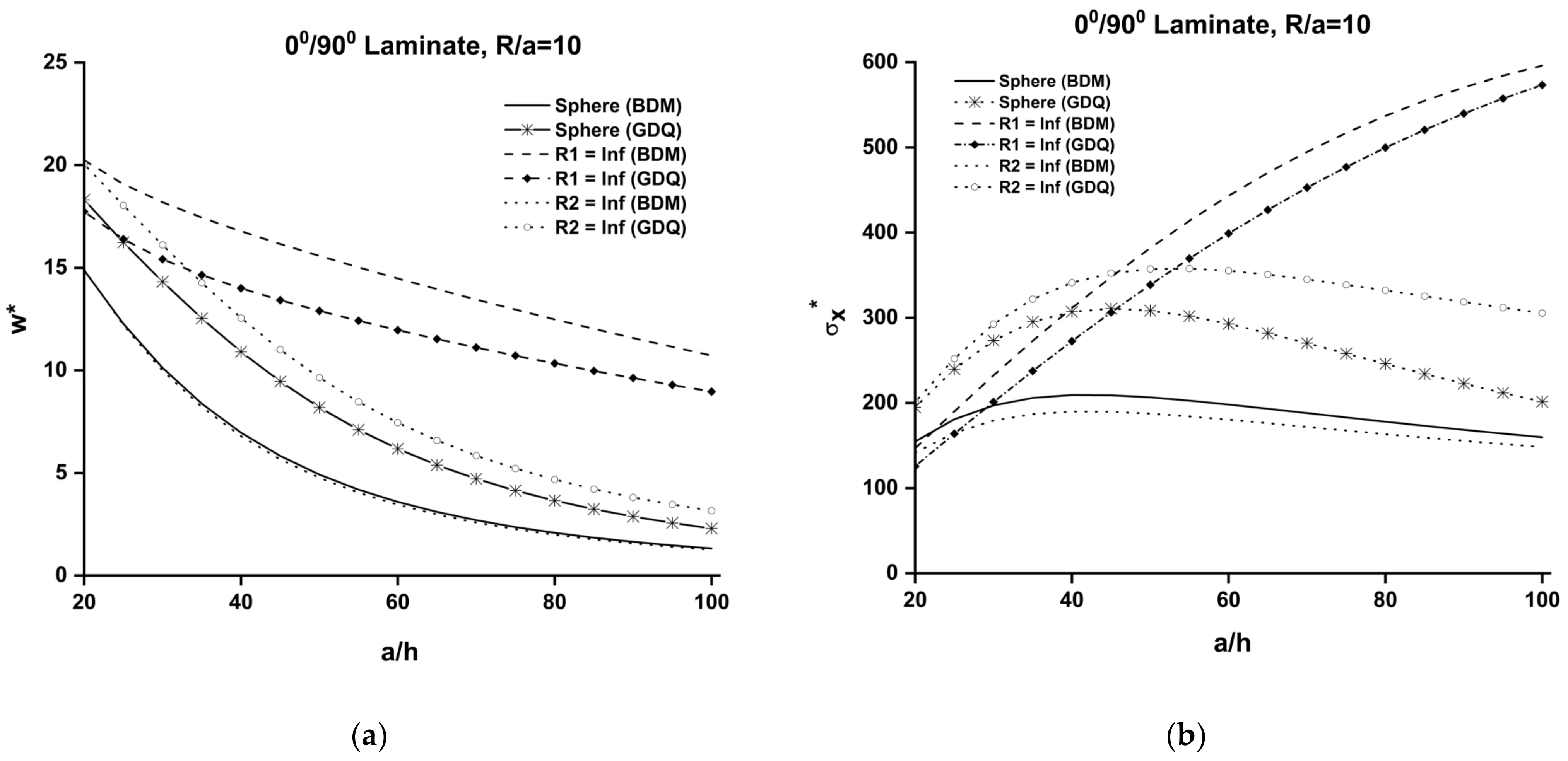
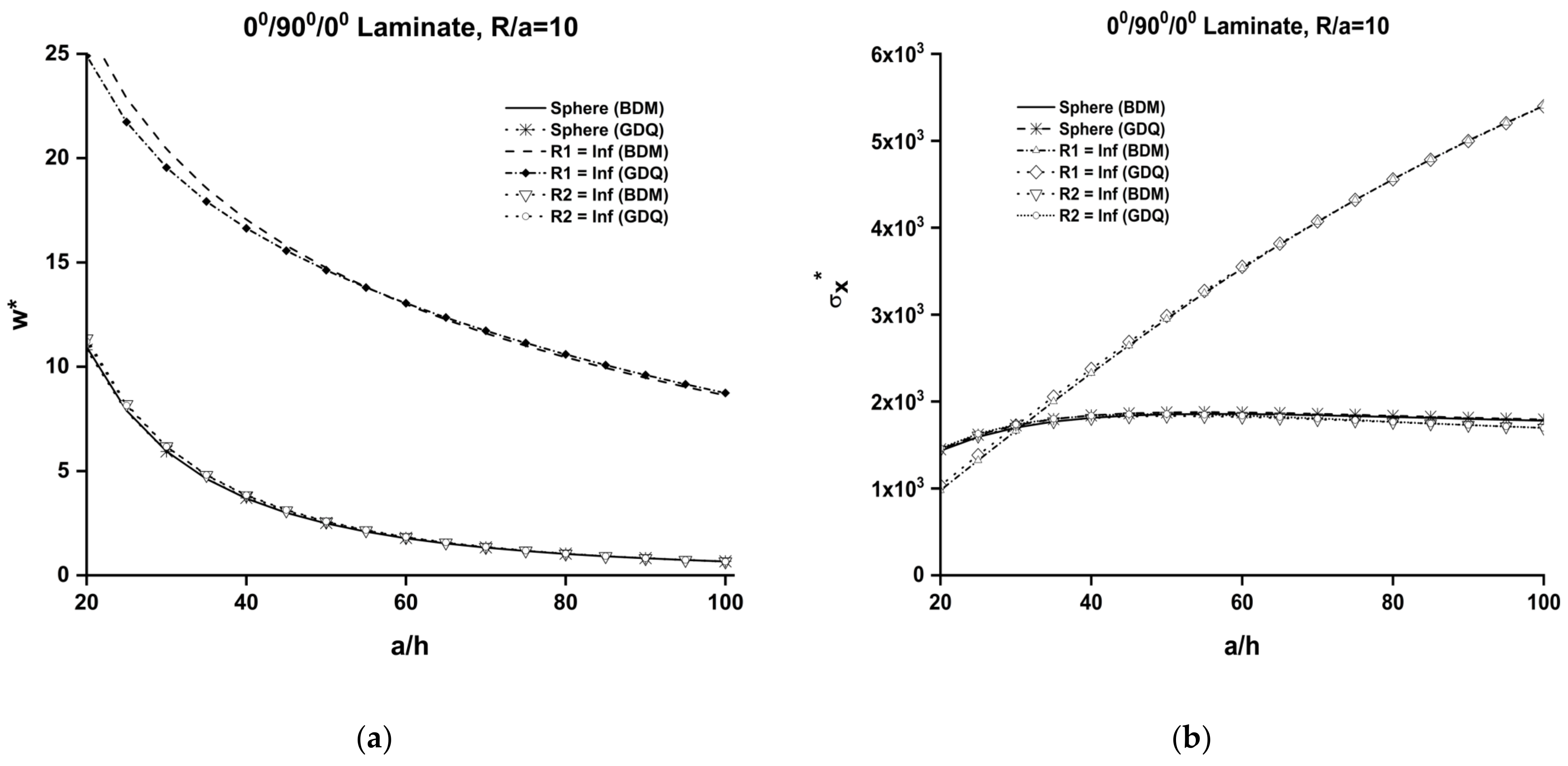
Variations of normalized central deflection, w*, and stresses, σ x , of spherical (R/a = 10) shell and two cylindrically curved panels for various length-to-thickness, a/h ratios under uniform loading are presented in Figure 3 for antisymmetric cross-ply [0°/90°] and Figure 4 for symmetric [0°/90°/0°] lamination, respectively. The transverse shear deformation curves of the [0°/90°] spherical and cylindrical panel, with R2 → ∞, are almost the same for the whole range of a/h ratio in the BDM method given in Figure 3a, as has already been observed in the case of the mixed simply supported boundary conditions in Reference [30]. While there is a relative difference between the BDM and GDQ methods for [0°/90°] spherical and cylindrical panels, normalized central deflection, w*, and stress, σ x , curves have similar characteristics for both methods. However, the normalized central deflection, w*, and stress, σ x , curves of symmetric [0°/90°/0°] spherical and cylindrical panels with R2 → ∞ are almost the same for the whole range of a/h ratio, as is shown in Figure 4. The normalized central deflection and stress results obtained with BDM for symmetric [0°/90°/0°] lamination are exactly matched with GDQ method. Variations of the normalized stress, σ x , of antisymmetric [0o/90o] and symmetric [0°/90°/0°] spherical and two cylindrically curved panels for different R/a ratios are individually displayed in Figure 3b and Figure 4b, respectively.
Figure 5 and Figure 6 present the variations of the normalized central deflection, w*, and stress, σ x , of moderately thick (a/h = 20) curved panels (one spherical and two cylindrical) with antisymmetric [0°/90°] and symmetric [0°/90°/0°] laminations with R/a ratio. Based on the present results, the spherical panel response was found to represent similar characteristic to those observed for its cylindrical counterpart, with R2 → ∞ for each R/a ratio value. Symmetric [0°/90°/0°] laminates also exhibited a similar trend. For symmetric [0°/90°/0°] lamination, non-dimensional displacements, w*, both for the spherical panel and cylindrical counterparts—as (R2 → ∞)—possess a flatter regime after R/a > 60, while non-dimensional displacement, w*, values in the cylindrical panel under R1 → ∞ conditions possess a flatter regime after R/a > 20. The normalized central deflection results for symmetric [0°/90°/0°] laminations obtained with BDM are exactly matched with the GDQ solution. Variations of the normalized stress, σ x , of the moderately thick (a/h = 20) antisymmetric [0°/90°] and symmetric ([0°/90°/0°] spherical and two cylindrically curved panels for different R/a ratios are individually displayed in Figure 5b and Figure 6b, respectively.
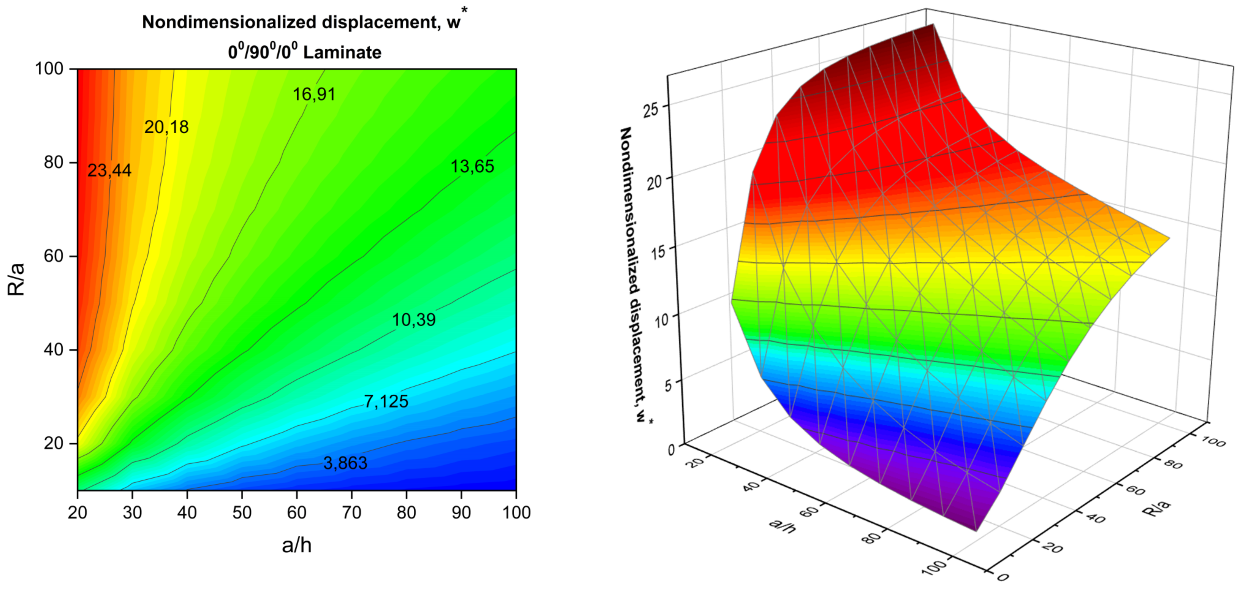
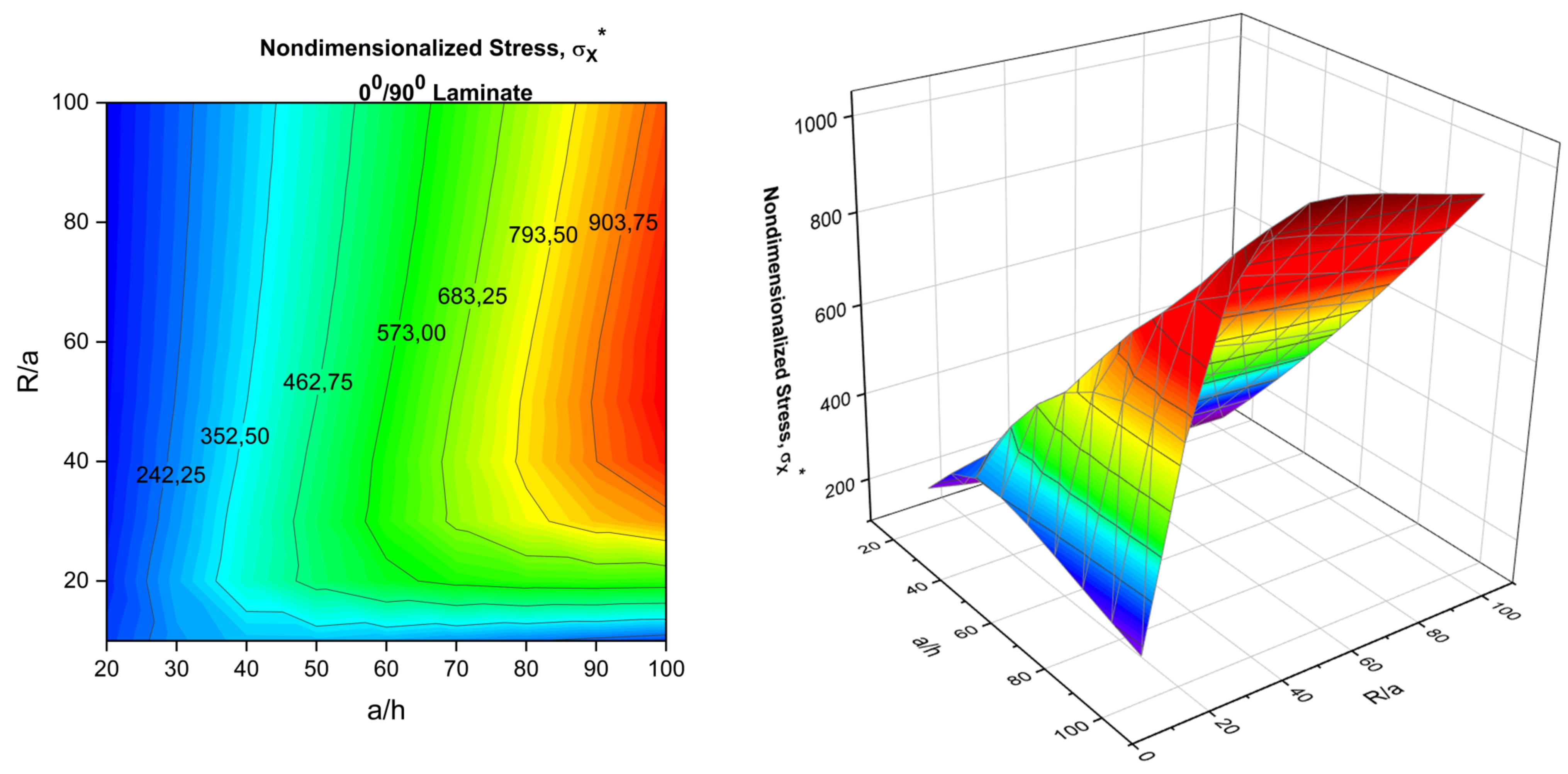
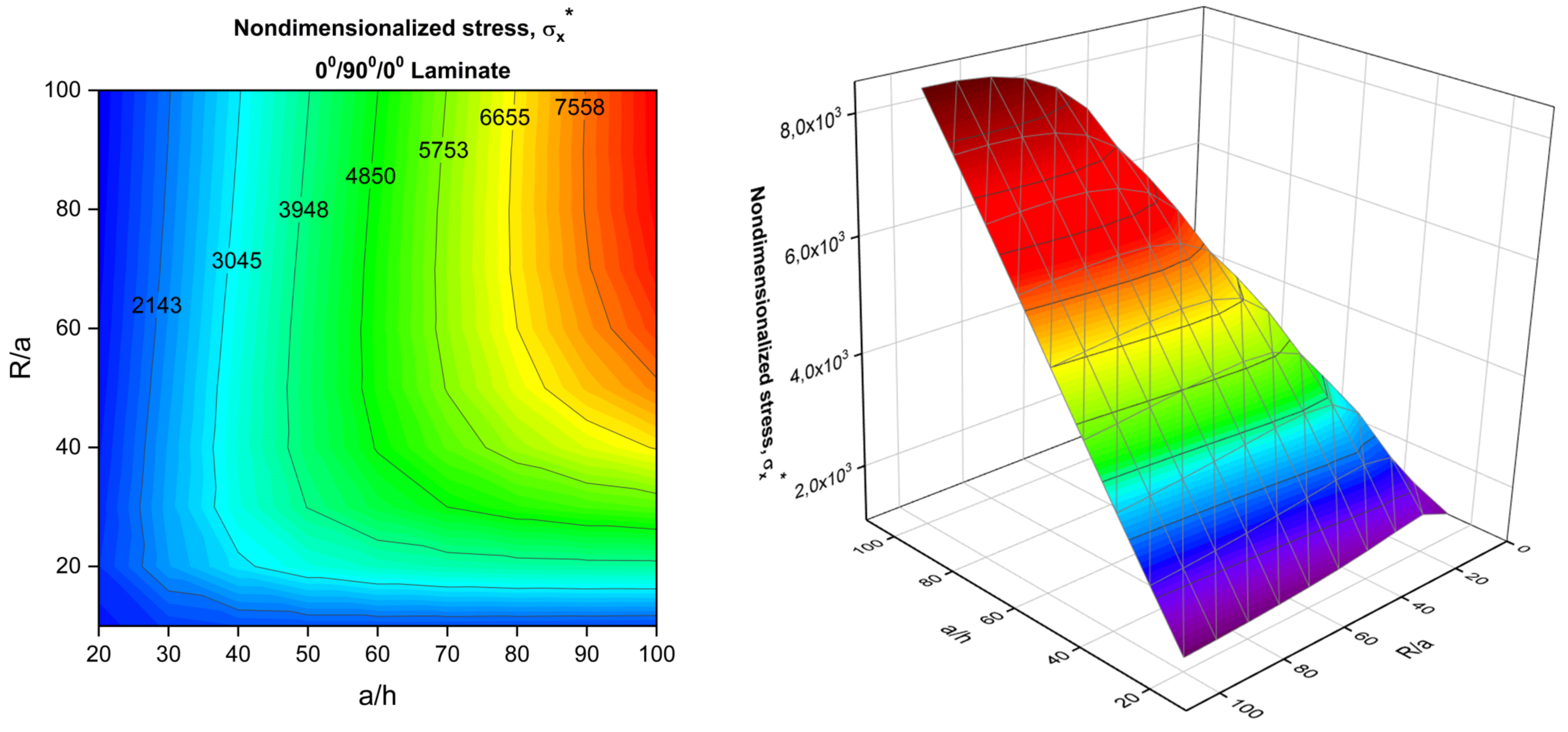
Figure 7 and Figure 8 present the nondimensional displacement, w*, of [0°/90°] and [0°/90°/0°] spherical panels with the change of R/a and a/h ratios, respectively. The impact of transverse shear deformation and the action of membrane owing to curvature on w* is observable. The curvature effect on transverse displacement, w*, also plays a critical role in the thinner shell regime, specifically beginning from the ratio R/a < 40. Bending–stretching coupling is inherent in antisymmetric laminations, and it directly impacts the interaction of membrane action with the beam–column/tie-bar effect. The membrane action due to curvature has a complicated interaction with the stated mechanism. This interaction must be considered for the prior design of composite shells. Figure 9 and Figure 10 display the variations of the normalized stresses, σ x , with a/h and R/a ratios for antisymmetric [0°/90°] and symmetric [0°/90°/0°] spherical panels, respectively. The membrane action has similar effect in both the thick and the thinner panel regime, particularly for R/a ≤ 40, as mentioned above.
Variations of the non-dimensional displacements, w , and stresses, σ x of a moderately thick (a/h = 20) shell panel (R/a = 10) of antisymmetric [0°/90°] cross-ply spherical panels, computed at the whole surface are presented in Figure 11 and Figure 12, respectively. Non-dimensional displacements, w*, and stresses, σ x , reached their maximum value at the center of the panel. It can be observed on the graphs that the boundary conditions were exactly satisfied by the boundary discontinuous double Fourier series method.

5. Conclusions

In this study, an analytical solution was presented using the boundary discontinuous Fourier series method for the static analysis of thick and shallow cylindrical, spherical panels in addition to plates (a special case of the shells) made of symmetric and antisymmetric cross-ply laminated composite material subjected to unsolved mixed type boundary conditions described on the edges. The governing equilibrium equations for laminated composite panels were obtained using the virtual work principle. Boundary Fourier coefficients arising from the discontinuity of the assumed functions and their derivatives at the boundaries were introduced in order to solve the complementary solution. Analytical solutions obtained with the BDM method were also compared with the successful integration of the generalized differential quadrature (GDQ) method. Comprehensive tabular and graphical results were displayed so as to show the effects of curvature on the deflections and stresses of thick shallow shells. The validity of the proposed model was authenticated with a review of the available literature, and the convergence characteristics were demonstrated. The changing trends of displacements and moments were explained in detail by investigating the effects of various parameters, such as lamination, material properties, curvature, etc. The numerical results could particularly be utilized during the early design stages of such laminated structures and as benchmark solutions for the future comparison of numerical results, such as finite element analysis and boundary element methods. The following are the major findings of the present research.
It is worth noting that almost no difference resulted from changing from moderately deep (R/a = 10) to (R/a = Plate) between BDM and GDQ for the very well-known SS3 type boundary conditions. The relatively small discrepancies between the present methodologies and the finite element method can be predicated to the variation between strong-form and weak-form formulations. Our proposed solution methodologies for BDM and GDQ methods are based on the strong form, as it satisfies the compulsory and natural boundary conditions. In contrast to strong-form, the finite element method uses the weak-form formulation and does not apply natural or force boundary conditions which are imposed on the secondary variable, such as forces and moments.
A rapid and monotonic convergence was observed with the Fourier series for the terms m, n > 10 for displacements and m, n > 20 for stress in the BDM. The stress convergence was higher than the displacement. This is possibly due to the presence of a discontinuity (complementary boundary constraint) in the derivative of the displacement in expression of the stress. The same convergence characteristics were observed for grid numbers m, n = 13 with the generalized differential quadrature method.
A difference was seen when changing from the range 11.28% (R/a = Plate) to 18.75% (R/a = 10) for moderately thick (a/h = 20) antisymmetric [0°/90°] plates and shell with the roller skate-type boundary condition prescribed on two opposite edges, while the remaining two edges were subjected to the simply supported constraint between the BDM and GDQ methods. This is possibly due to the presence of a discontinuity in the derivatives which comes from the bending–stretching matrix (B matrix presence) in antisymmetric lamination. However very close results were obtained for symmetric ([0°/90°/0°] plates and shells using the whole range R/a and a/h ratios. It is also important to state that all three methods (BDM, DQM, and FEM) use different formulations, and among them, BDM provides analytical solutions and satisfies boundary conditions exactly, as is shown in Table 2 compared to FEM and DQM.
The difference between BDM and GDQ for an antisymmetric [0°/90°] shell increases with the increase of (E1/E2). The reason for this may be the dominant discontinuity in the bending–stretching matrix (B matrix presence) in antisymmetric lamination.
The effect of the modulus ratio, E1/E2, was more pronounced in the thin laminates (a/h > 50). Furthermore, this effect was increased by the beam–column effect in the case of an antisymmetric laminate. This is because the bending–stretching coupling is dominant in an antisymmetric laminate and produces a softening effect on the beam–column type, which consequently increases the normalized central deflection.
The effect of the radius-to-length ratio R/a on transverse displacement, w*, also plays a critical role in the thinner shell regime, specifically beginning from the ratio R/a < 40. Bending–stretching coupling is inherited in antisymmetric laminations, and it directly impacts the interaction of membrane action with the beam–column/tie-bar effect. The membrane action due to curvature has a complicated interaction with the stated mechanism. This interaction should be considered during the prior design of composite shells.

Author Contributions

Conceptualization, İ.A.; methodology, İ.A., A.S.O., software, İ.A.; validation, İ.A.; formal analysis, İ.A.; investigation, İ.A.; resources, İ.A., A.S.O.; data curation, İ.A.; writing—original draft preparation, İ.A.; writing—review and editing, İ.A., A.S.O.; visualization, İ.A.; supervision, A.S.O. All authors have read and agreed to the published version of the manuscript.

Funding

This research received no external funding.

Data Availability Statement

Not applicable.

Conflicts of Interest

The authors declare no conflict of interest.

Appendix A

The unknown boundary Fourier coefficients are defined as follows:
a ¯ n = 4 a b 0 b u 1 , 1 a , ξ 2 u 1 , 1 0 , ξ 2 sin ( β ξ 2 ) d ξ 2 ,
b ¯ n = 4 a b 0 b u 1 , 1 a , ξ 2 + u 1 , 1 0 , ξ 2 sin ( β ξ 2 ) d ξ 2 ,
c ¯ n = 4 a b 0 b u 3 a , ξ 2 u 3 0 , ξ 2 cos ( β ξ 2 ) d ξ 2 ,
d ¯ n = 4 a b 0 b u 3 a , ξ 2 + u 3 0 , ξ 2 cos ( β ξ 2 ) d ξ 2 ,

Appendix B

Definition of the Constants in Equations (31)–(39)
f 1 = A 55 R 1 ;     f 2 = c 2 D 66 ,
f 3 = f 1 + g 1 ;         f 4 = A 66 β 2 2 + c 2 D 66 β 2 2 ;   f 5 = A 44 R 2 2 ,
f 6 = A 12 β R 1 + A 22 β R 2 + A 44 β R 2 ,
f 7 = B 22 β 2 + A 44 R 2 + c D 66 α 2 ,
f 8 = A 11 R 1 + A 12 R 2 ,
f 9 = A 12 R 1 + A 22 R 2 ,   f 10 = A 44 β 2 + A 55 α 2 ,
f 11 = B 11 α R 1 A 55 α ,   f 12 = B 22 β R 2 A 44 β ,
f 13 = B 11 R 1 ,   f 14 = B 22 R 1 ,
f 15 = D 22 β 2 D 66 α 2 A 44 ,
g 1 = A 11 R 1 + A 12 R 2 ,   g 2 = D 66 β 2 D 11 α 2 A 55

References

  1. Love, A.E.H. A Treatise on the Mathematical Theory of Elasticity; Cambridge University Press: Cambridge, UK, 2013; ISBN 1107618096. [Google Scholar]
  2. Donnell, L.H. A Discussion of Thin Shell Theory. In Proceedings of the 5th International Congress of Applied Mechanics, New York, NY, USA, 12–16 September 1938. [Google Scholar]
  3. Sanders, J.L. An Improved First-Approximation Theory for Thin Shells; US Government Printing Office: Washington, DC, USA, 1960; Volume 24.
  4. Timoshenko, S.; Woinowsky-Krieger, S. Theory of Plates and Shells; McGraw-Hill: New York, NY, USA, 1959; Volume 2. [Google Scholar]
  5. Reissner, E. A New Derivation of the Equations for the Deformation of Elastic Shells. Am. J. Math. 1941, 63, 177–184. [Google Scholar] [CrossRef]
  6. Qatu, M.S.; Asadi, E.; Wang, W. Review of Recent Literature on Static Analyses of Composite Shells: 2000–2010. Open J. Compos. Mater. 2012, 2, 61. [Google Scholar] [CrossRef] [Green Version]
  7. Liew, K.M.; Zhao, X.; Ferreira, A.J.M. A Review of Meshless Methods for Laminated and Functionally Graded Plates and Shells. Compos. Struct. 2011, 93, 2031–2041. [Google Scholar] [CrossRef]
  8. Gupta, A.; Talha, M. Recent Development in Modeling and Analysis of Functionally Graded Materials and Structures. Prog. Aerosp. Sci. 2015, 79, 1–14. [Google Scholar] [CrossRef]
  9. Van Dung, N.; Tho, N.C.; Ha, N.M.; Hieu, V.T. On the Finite Element Model of Rotating Functionally Graded Graphene Beams Resting on Elastic Foundation. Math. Probl. Eng. 2021, 2021, 1586388. [Google Scholar] [CrossRef]
  10. Nam, V.H.; van Vinh, P.; van Chinh, N.; van Thom, D.; Hong, T.T. A New Beam Model for Simulation of the Mechanical Behaviour of Variable Thickness Functionally Graded Material Beams Based on Modified First Order Shear Deformation Theory. Materials 2019, 12, 404. [Google Scholar] [CrossRef] [Green Version]
  11. Bui, T.Q.; Doan, D.H.; van Do, T.; Hirose, S.; Duc, N.D. High Frequency Modes Meshfree Analysis of Reissner–Mindlin Plates. J. Sci. Adv. Mater. Devices 2016, 1, 400–412. [Google Scholar] [CrossRef] [Green Version]
  12. Pagano, N.J. Exact Solutions for Rectangular Bidirectional Composites and Sandwich Plates. J. Compos. Mater. 1970, 4, 20–34. [Google Scholar] [CrossRef]
  13. Fan, J.; Zhang, J. Analytical Solutions for Thick, Doubly Curved, Laminated Shells. J. Eng. Mech. 1992, 118, 1338–1356. [Google Scholar] [CrossRef]
  14. Kumari, P.; Kar, S. Static Behavior of Arbitrarily Supported Composite Laminated Cylindrical Shell Panels: An Analytical 3D Elasticity Approach. Compos. Struct. 2019, 207, 949–965. [Google Scholar] [CrossRef]
  15. Atashipour, S.R.; Girhammar, U.A.; Al-Emrani, M. Exact Lévy-Type Solutions for Bending of Thick Laminated Orthotropic Plates Based on 3-D Elasticity and Shear Deformation Theories. Compos. Struct. 2017, 163, 129–151. [Google Scholar] [CrossRef]
  16. Nik, A.M.N.; Tahani, M. Analytical Solutions for Bending Analysis of Rectangular Laminated Plates with Arbitrary Lamination and Boundary Conditions. J. Mech. Sci. Technol. 2009, 23, 2253–2267. [Google Scholar] [CrossRef]
  17. Whitney, J.M.; Leissa, A.W. Analysis of a Simply Supported Laminated Anisotropic Rectangular Plate. AIAA J. 1970, 8, 28–33. [Google Scholar] [CrossRef]
  18. Reddy, J.N.; Liu, C. A Higher-Order Shear Deformation Theory of Laminated Elastic Shells. Int. J. Eng. Sci. 1985, 23, 319–330. [Google Scholar] [CrossRef]
  19. Huang, Y.; Yuan, D.-C. Static Analysis of Symmetric Angle-Ply Laminated Plates by Analytical Method. AIAA J. 2006, 44, 667–669. [Google Scholar] [CrossRef]
  20. Li, H.; Liu, N.; Pang, F.; Du, Y.; Li, S. An Accurate Solution Method for the Static and Vibration Analysis of Functionally Graded Reissner-Mindlin Rectangular Plate with General Boundary Conditions. Shock Vib. 2018, 2018, 4535871. [Google Scholar] [CrossRef] [Green Version]
  21. Chaudhuri, R.A. On the Roles of Complementary and Admissible Boundary Constraints in Fourier Solutions to the Boundary Value Problems of Completely Coupled r Th Order PDEs. J. Sound Vib. 2002, 251, 261–313. [Google Scholar] [CrossRef]
  22. Chaudhuri, R.A. On Boundary-Discontinuous Double Fourier Series Solution to a System of Completely Coupled PDE’s. Int. J. Eng. Sci. 1989, 27, 1005–1022. [Google Scholar] [CrossRef]
  23. Chaudhuri, R.A.; Kabir, H.R.H. On Analytical Solutions to Boundary-Value Problems of Doubly-Curved Moderately-Thick Orthotropic Shells. Int. J. Eng. Sci. 1989, 27, 1325–1336. [Google Scholar] [CrossRef]
  24. Chaudhuri, R.A.; Kabir, H.R.H. Sensitivity of the Response of Moderately Thick Cross-Ply Doubly-Curved Panels to Lamination and Boundary Constraint-I. Theory. Int. J. Solids Struct. 1993, 30, 263–272. [Google Scholar] [CrossRef]
  25. Chaudhuri, R.A.; Kabir, H.R.H. Boundary-Discontinuous Fourier Analysis of Doubly-Curved Panels Using Classical Shallow Shell Theories. Int. J. Eng. Sci. 1993, 31, 1551–1564. [Google Scholar] [CrossRef]
  26. Chaudhuri, R.A.; Abu-Arja, K.R. Exact Solution of Shear-Flexible Doubly Curved Anti-Symmetric Angle-Ply Shells. Int. J. Eng. Sci. 1988, 26, 587–604. [Google Scholar] [CrossRef]
  27. Chaudhuri, R.A.; Abu-Arja, K.R. Static Analysis of Moderately-Thick Finite Antisymmetric Angle-Ply Cylindrical Panels and Shells. Int. J. Solids Struct. 1991, 28, 1–15. [Google Scholar] [CrossRef]
  28. Oktem, A.S.; Chaudhuri, R.A. Levy Type Analysis of Cross-Ply Plates Based on Higher-Order Theory. Compos. Struct. 2007, 78, 243–253. [Google Scholar] [CrossRef]
  29. Oktem, A.S.; Chaudhuri, R.A. Fourier Analysis of Thick Cross-Ply Levy Type Clamped Doubly-Curved Panels. Compos. Struct. 2007, 80, 489–503. [Google Scholar] [CrossRef]
  30. Oktem, A.S.; Chaudhuri, R.A. Levy Type Fourier Analysis of Thick Cross-Ply Doubly Curved Panels. Compos. Struct. 2007, 80, 475–488. [Google Scholar] [CrossRef]
  31. Oktem, A.S.; Chaudhuri, R.A. Boundary Discontinuous Fourier Analysis of Thick Cross-Ply Clamped Plates. Compos. Struct. 2008, 82, 539–548. [Google Scholar] [CrossRef]
  32. Mantari, J.L.; Oktem, A.S.; Soares, C.G. Static and Dynamic Analysis of Laminated Composite and Sandwich Plates and Shells by Using a New Higher-Order Shear Deformation Theory. Compos. Struct. 2011, 94, 37–49. [Google Scholar] [CrossRef]
  33. Oktem, A.S.; Soares, C.G. Higher Order Theory Based Fourier Analysis of Cross-Ply Plates and Doubly Curved Panels. J. Compos. Mater. 2012, 46, 2675–2694. [Google Scholar] [CrossRef]
  34. Chaudhuri, R.A.; Balaraman, K.; Kunukkasseril, V.X. A Combined Theoretical and Experimental Investigation on Free Vibration of Thin Symmetrically Laminated Anisotropic Plates. Compos. Struct. 2005, 67, 85–97. [Google Scholar] [CrossRef]
  35. Viola, E.; Tornabene, F.; Fantuzzi, N. Static Analysis of Completely Doubly-Curved Laminated Shells and Panels Using General Higher-Order Shear Deformation Theories. Compos. Struct. 2013, 101, 59–93. [Google Scholar] [CrossRef]
  36. Asadi, E.; Qatu, M.S. Static Analysis of Thick Laminated Shells with Different Boundary Conditions Using GDQ. Thin-Walled Struct. 2012, 51, 76–81. [Google Scholar] [CrossRef]
  37. Kurtaran, H. Geometrically Nonlinear Transient Analysis of Moderately Thick Laminated Composite Shallow Shells with Generalized Differential Quadrature Method. Compos. Struct. 2015, 125, 605–614. [Google Scholar] [CrossRef]
  38. Kurtaran, H. Geometrically Nonlinear Transient Analysis of Thick Deep Composite Curved Beams with Generalized Differential Quadrature Method. Compos. Struct. 2015, 128, 241–250. [Google Scholar] [CrossRef]
  39. Tornabene, F.; Fantuzzi, N.; Bacciocchi, M. The Local GDQ Method for the Natural Frequencies of Doubly-Curved Shells with Variable Thickness: A General Formulation. Compos. B Eng. 2016, 92, 265–289. [Google Scholar] [CrossRef]
  40. Tornabene, F.; Viscoti, M.; Dimitri, R. Higher Order Theories for the Free Vibration Analysis of Laminated Anisotropic Doubly-Curved Shells of Arbitrary Geometry with General Boundary Conditions. Compos. Struct. 2022, 297, 115740. [Google Scholar] [CrossRef]
  41. Allahkarami, F.; Tohidi, H.; Dimitri, R.; Tornabene, F. Dynamic Stability of Bi-Directional Functionally Graded Porous Cylindrical Shells Embedded in an Elastic Foundation. Appl. Sci. 2020, 10, 1345. [Google Scholar] [CrossRef] [Green Version]
  42. Zare Jouneghani, F.; Dimitri, R.; Bacciocchi, M.; Tornabene, F. Free Vibration Analysis of Functionally Graded Porous Doubly-Curved Shells Based on the First-Order Shear Deformation Theory. Appl. Sci. 2017, 7, 1252. [Google Scholar] [CrossRef] [Green Version]
  43. Kiarasi, F.; Babaei, M.; Asemi, K.; Dimitri, R.; Tornabene, F. Three-Dimensional Buckling Analysis of Functionally Graded Saturated Porous Rectangular Plates under Combined Loading Conditions. Appl. Sci. 2021, 11, 10434. [Google Scholar] [CrossRef]
  44. Tornabene, F.; Fantuzzi, N.; Bacciocchi, M.; Viola, E.; Reddy, J.N. A Numerical Investigation on the Natural Frequencies of FGM Sandwich Shells with Variable Thickness by the Local Generalized Differential Quadrature Method. Appl. Sci. 2017, 7, 131. [Google Scholar] [CrossRef]
  45. Reddy, J.N. Mechanics of Laminated Composite Plates and Shells: Theory and Analysis; CRC Press: Boca Raton, FL, USA, 2003; ISBN 0203502809. [Google Scholar]
  46. Hobson, E.W. The Theory of Functions of a Real Variable and the Theory of Fourier’s Series; The University Press: Cambridge, UK, 1921; Volume 1. [Google Scholar]
  47. Green, A.E. Double Fourier Series and Boundary Value Problems. Math. Proc. Camb. Philos. Soc. 1944, 40, 222–228. [Google Scholar] [CrossRef]
  48. Shu, C.; Du, H. A Generalized Approach for Implementing General Boundary Conditions in the GDQ Free Vibration Analysis of Plates. Int. J. Solids Struct. 1997, 34, 837–846. [Google Scholar] [CrossRef]
  49. Oktem, A.S.; Chaudhuri, R.A. Effect of Inplane Boundary Constraints on the Response of Thick General (Unsymmetric) Cross-Ply Plates. Compos. Struct. 2008, 83, 1–12. [Google Scholar] [CrossRef]
Figure 1. Geometry of a laminated doubly curved panel.
Applsci 12 12547 g001
Figure 2. Convergence of displacements, w , and stresses, σ x , of a moderately thick (a/h = 20) and symmetric cross-ply (0°/90°/0°) spherical panel (R/a = 10).
Applsci 12 12547 g002
Figure 3. (a) Variation of the non-dimensional displacement, w , and (b) non-dimensional stresses, σ x , with a/h ratio for antisymmetric [0°/90°] spherical and cylindrical panels (R/a = 10).
Applsci 12 12547 g003
Figure 4. (a) Variation of non-dimensional displacement, w , and (b) non-dimensional stresses, σ x , with the a/h ratio for symmetric [0°/90°/0°] spherical and cylindrical panels (R/a = 10).
Applsci 12 12547 g004
Figure 5. (a) Variation of non-dimensional displacement, w , and (b) non-dimensional stresses, σ x , of moderately thick (a/h = 20) curved panels (one spherical and two cylindrical) with an R/a ratio for antisymmetric [0°/90°] lamination.
Applsci 12 12547 g005
Figure 6. (a)Variation of non-dimensional displacement, w , and (b) non-dimensional stresses, σ x , of moderately thick (a/h = 20) curved panels (one spherical and two cylindrical) with an R/a ratio for symmetric [0°/90°/0°] lamination.
Applsci 12 12547 g006
Figure 7. Nondimensional displacement, w*, of (0°/90°) spherical panels with the change of R/a and a/h ratios.
Applsci 12 12547 g007
Figure 8. Nondimensional displacement, w*, of (0°/90°/0°) spherical panels with the change of R/a and a/h ratios.
Applsci 12 12547 g008
Figure 9. Nondimensional stresses, σ x , of (0°/90°) spherical panels with the change of R/a and a/h ratios.
Applsci 12 12547 g009
Figure 10. Nondimensional stresses, σ x , of (0°/90°/0°) spherical panels with the change of R/a and a/h ratios.
Applsci 12 12547 g010
Figure 11. Variations of the non-dimensional displacements, w , of a moderately thick (a/h = 20) shell panel (R/a = 10) and of antisymmetric [0°/90°] cross-ply spherical panels along the panel surface.
Applsci 12 12547 g011
Figure 12. Variations of the non-dimensional stresses, σ x , of a moderately thick (a/h = 20) shell panel (R/a = 10) and of antisymmetric [0°/90°] cross-ply spherical panels along the panel surface.
Applsci 12 12547 g012
Table 1. Normalized central deflections and stresses of cross-ply laminated shells under distributed load (a/h = 100).
[0°/90°][0°/90°/0°][0°/90°/90°/0°]
R/a BDMGDQRef. [18]BDMGDQRef. [18]BDMGDQRef. [18]
10 w 5.54285.5425.54283.6443.6443.64453.7203.7203.720
2011.27311.2711.2735.5475.5475.54735.6615.6615.661
5015.71415.7115.7146.4826.4826.48276.6146.6146.614
10016.64516.6416.6456.6426.6426.64216.7776.7776.777
Plate16.97916.9716.9806.6976.6966.69706.8336.8336.842
R/a BDMGDQFEMBDMGDQFEMBDMGDQFEM
10 σ x 420.17420.2418.984688.64688.64678.54961.84961.84954.4
20868.116868.1866.1806962.9696369507238.27238.27227
501196.101196.111967956.67956.77985.28175.88175.88209.2
1001256.621256.61255.68081.28081.38075827182718265.9
Plate1268.701268.71267.48073807380648229.68229.58222.7
Table 2. Normalized central deflections of cross-ply [0°/90°] laminated shells under uniform load. With SS–RS boundary conditions (a/h = 20).
R/aBDMGDQFEM
1014.88018.31520.900
w 2020.76320.79622.165
Plate22.15219.90122.603
10154.778194.918142.100
σ x 20172.361176.382129.650
Plate136.668118.459105.135
101850.12323.42569.2
σ y 202612.82614.22684.3
Plate2785.62466.02690.4
Table 3. Normalized central deflections of cross-ply laminated shells under uniform load.
[0°/90°][0°/90°/0°][0°/90°/90°/0°]
R/aa/hMethodw* σ x   σ y w* σ x σ y w* σ x σ y
1020BDM14.880154.7781850.110.9501432.6101.04610.9991489.3110.386
GDQ18.315194.9182323.410.8111450.899.454310.8641510.8108.887
50BDM4.9204206.6151460.82.4851851.640.883.1181239476.979
GDQ8.1924308.40526902.5081874.741.7463.14432419.078.042
100BDM1.3248159.760550.630.6661778.99.19410.92362499.936.3349
GDQ2.3004201.4571313.90.6711792.59.96370.93042518.537.3247
Plate20BDM22.147136.554278528.660944.08269.43420.966769.890200.210
GDQ19.901118.4592466.027.0581004.4252.1320.190828.9191.707
50BDM19.818399.6296406.519.5983048.2436.8015.7862680.8390.017
GDQ17.114338.5545439.219.4693070.2458.0715.8532681.5389.6595
100BDM19.193837.1661244.516.7996544.3793.0214.1375893.2703.959
GDQ16.588695.9111058.217.9766381.6846.77914.985622.0741.542
Table 4. Normalized central deflections of cross-ply [0°/90°] laminated shells under uniform load.
R/aa/hMethodE1/E2
31020304050
w*1020BDM33.87723.800617.04713.17110.6558.902
GDQ34.55925.926820.21816.76914.39212.638
50BDM16.0559.3365.8604.2293.2832.668
GDQ17.22212.1089.1307.4446.3145.494
100BDM5.42332.72621.60041.12920.86990.705
GDQ5.83183.6652.60412.06771.73061.495
Plate20BDM41.70831.44924.46420.27717.42715.346
GDQ39.95228.52421.94218.27415.83314.059
50BDM37.95328.48221.97718.07715.42913.500
GDQ36.68325.32019.00715.60913.39611.810
100BDM36.99527.69921.31117.48714.89513.010
GDQ36.12324.73418.44815.08912.91411.362
σ x 1020BDM408.591268.165181.547134.061104.29384.170
GDQ420.420294.297218.847175.913147.473127.130
50BDM727.107402.740247.767176.540135.605109.158
GDQ755.659480.335346.930278.613234.863203.835
100BDM696.610332.097193.171136.115104.81985.020
GDQ706.825363.486233.464178.37146.929126.241
Plate20BDM344.536231.245159.110118.96093.38675.828
GDQ338.443212.727139.872101.94378.76263.292
50BDM932.956647.333459.655352.222282.161233.055
GDQ895.587582.226394.657294.155231.333188.603
100BDM1905.61336.1958.7740.8597.8496.9
GDQ1808.31183.6807.6605.1478391.2
σ y 1020BDM834.21380.21747.41922.32009.32051.6
GDQ8581525.62111.62499.82776.92984.3
50BDM1085.21373.31453.21460.31447.61428.7
GDQ118418942480.728663141.93350
100BDM731.916670.952579.850528.011495.387472.958
GDQ811.31060.71244.813741474.61557
Plate20BDM967.91795.52521.23006.73361.33634.6
GDQ921.11601.72225.82672.73016.93293.2
50BDM2259.04162.75810.86906.97708.38329.4
GDQ2166.536334934.75869.56600.47198.3
100BDM4428812711,30313,40114,92916,112
GDQ42857123961111,39012,78113,921
Table 5. Normalized central deflections of cross-ply [0°/90°/0°] laminated shells under uniform load.
R/aa/hMethodE1/E2
31020304050
w*1020BDM32.25919.21512.7319.6207.7556.504
GDQ31.79518.86412.5449.5147.6926.466
50BDM13.2605.6323.0592.0911.5871.277
GDQ13.3445.6783.0862.1111.6011.289
100BDM4.3561.6310.8340.5540.4140.329
GDQ4.3571.6350.8390.5590.41770.332
Plate20BDM43.81834.61630.07427.49325.59724.062
GDQ42.63132.96828.41925.95424.19222.785
50BDM37.06525.62720.85018.65317.26316.240
GDQ37.14625.55920.72818.52017.13216.116
100BDM35.24023.01518.04715.88314.58513.674
GDQ36.17324.16919.23517.04215.70114.742
σ x 1020BDM875.11245.61395.21459.51496.11519.9
GDQ886.21264.11413.81477.51513.61537.1
50BDM1550.21865.418671836.21809.61788.7
GDQ1555.81883.51889.31859.81833.71813.1
100BDM15591798.81792.41765.91743.51725.8
GDQ1554.91802.41803.41781.61762.41747
Plate20BDM699.61927.91956.36931.67895.94858.31
GDQ720.6972.11011.4991.6958.5922.4
50BDM1998.12828.23033.53041.72998.12936.2
GDQ1993.228393052.93065.730252965.3
100BDM4140.55968.86481.16559.96519.66434.3
GDQ4059.65843.363286388.96334.76237.9
σ y 1020BDM361.159190.887119.38387.68869.43057.484
GDQ357.635187.504117.34786.42468.60156.918
50BDM409.137127.94654.63932.17822.03216.464
GDQ412.912129.88655.70132.89822.57416.899
100BDM265.09751.62714.3686.3623.6012.383
GDQ264.01752.36115.1907.0744.2082.906
Plate20BDM452.400334.082283.944257.786239.216224.367
GDQ440.178316.606266.128241.087223.864210.326
50BDM993.809632.001496.701439.754405.647381.325
GDQ992.951627.821491.164433.981399.974375.874
100BDM1910.41142859.2746681.9638.5
GDQ1947.41193.2913.2799.1733.2687.7
Publisher’s Note: MDPI stays neutral with regard to jurisdictional claims in published maps and institutional affiliations.