
Study on the Deformation Induced by Vertical Two-Layer Large Diameter Pipe-Jacking in the Soil-Rock Composite Stratum


Abstract
:1. Introduction
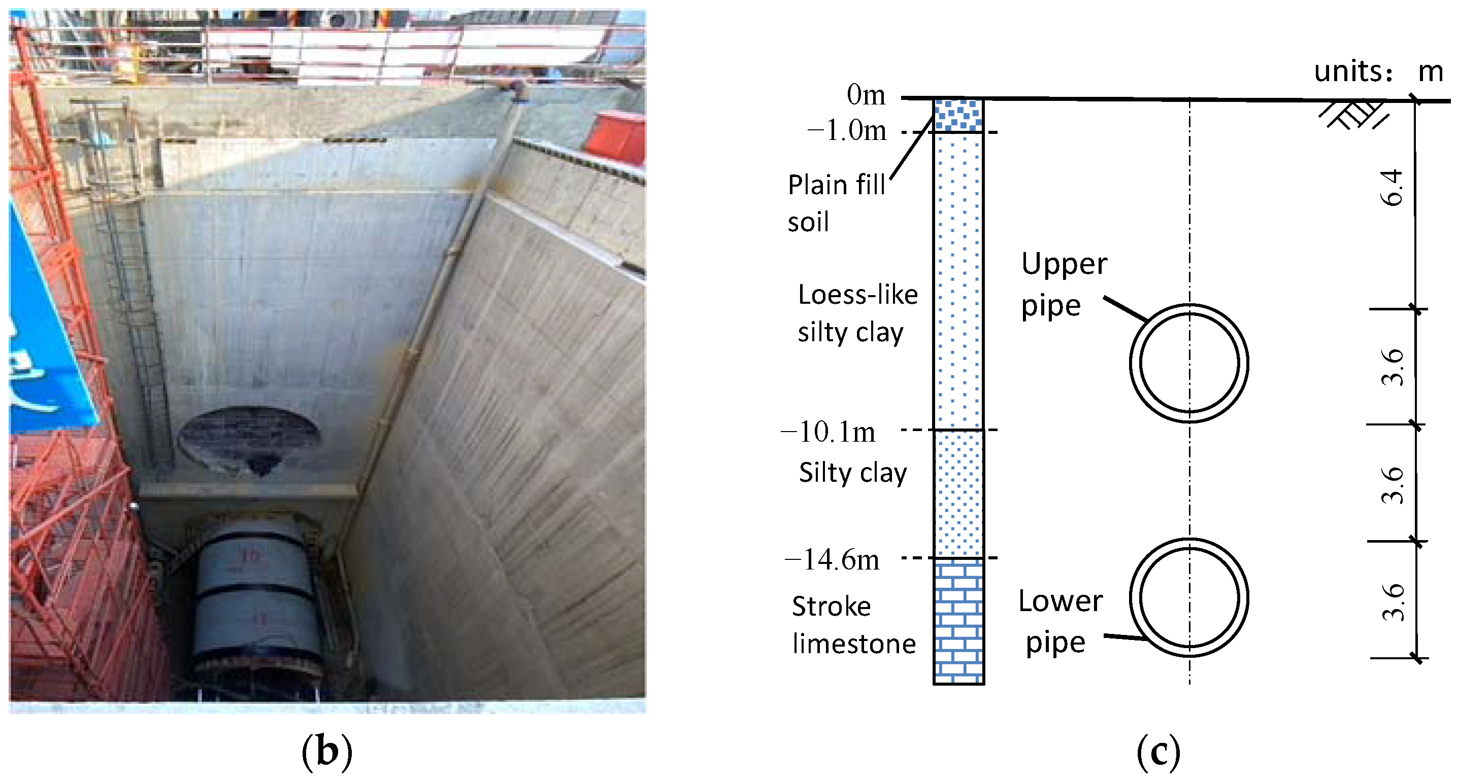
2. Project Overview
3. On-Site Monitoring Arrangement
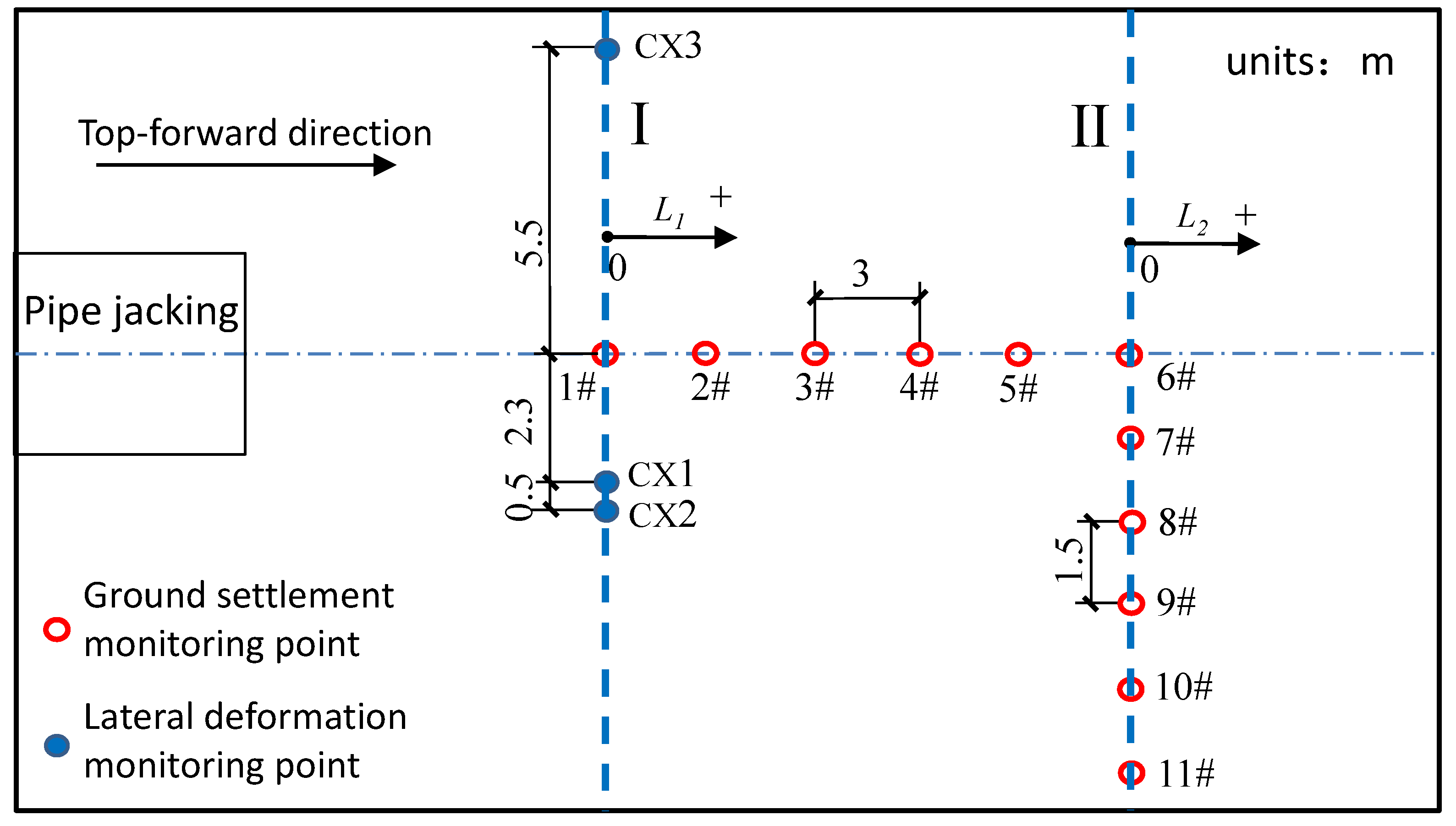
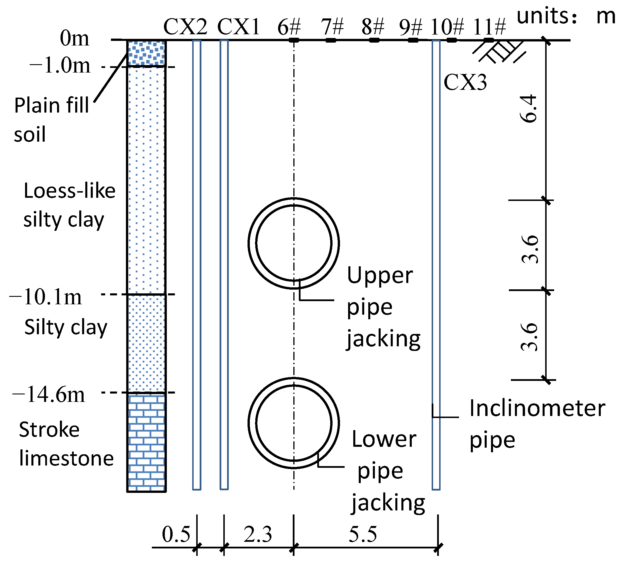
3.1. Layout of On-Site Monitoring Points
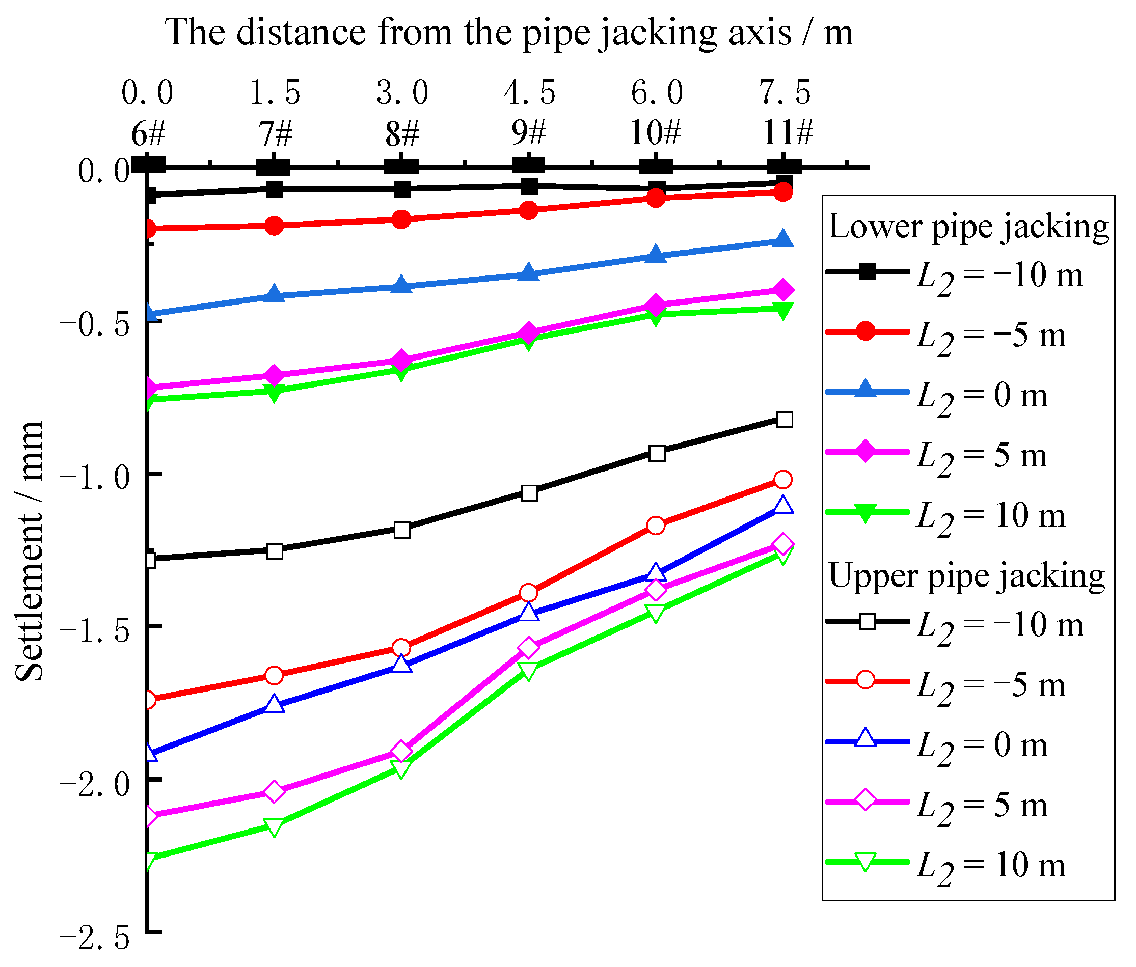
3.2. Transverse Ground Settlement
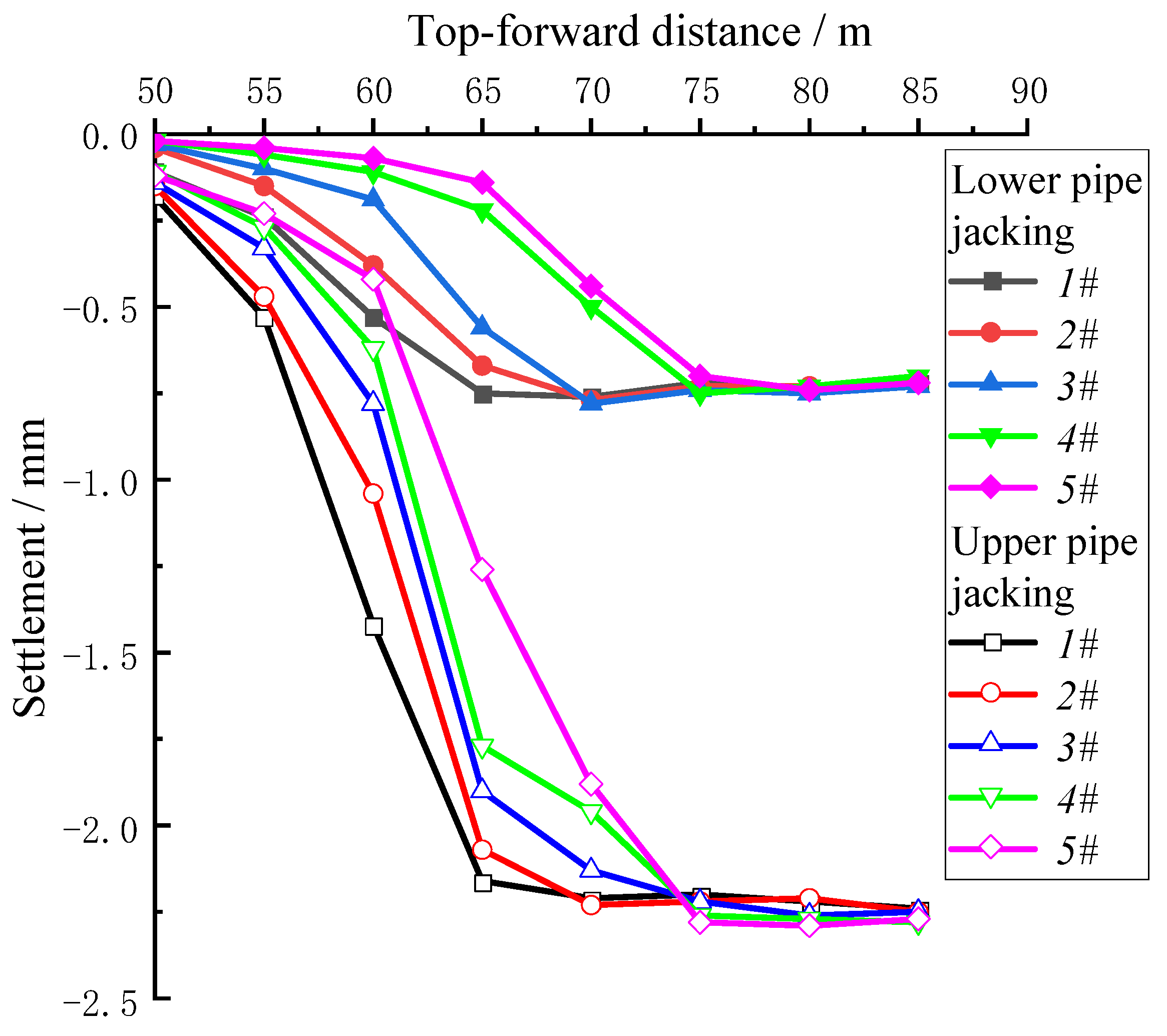
3.3. Longitudinal Ground Settlement
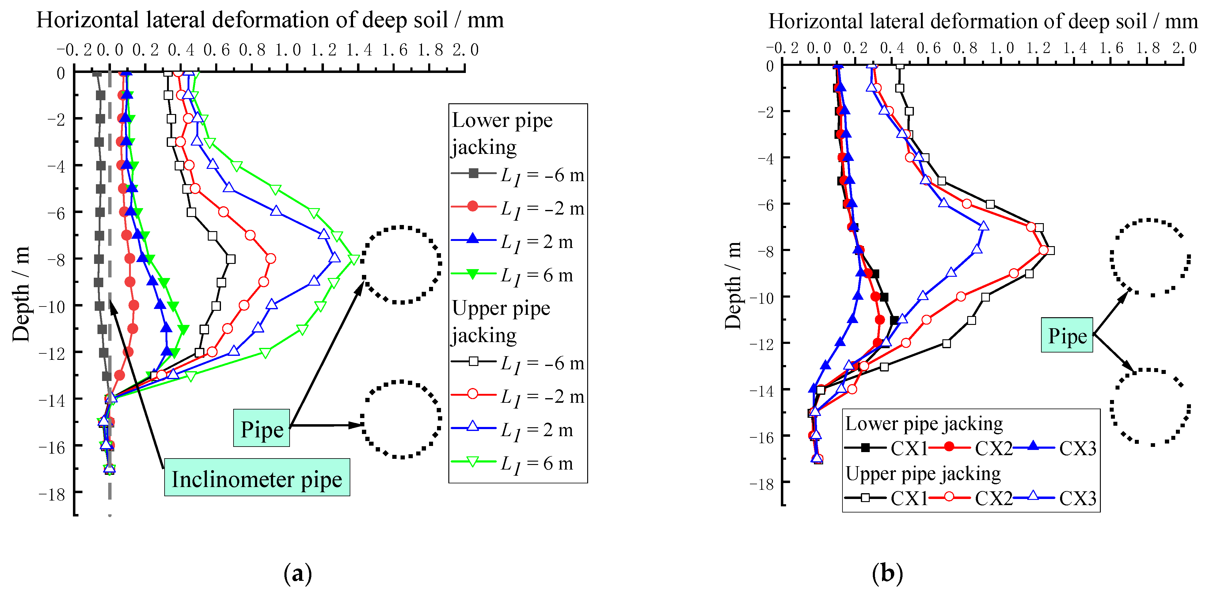
3.4. Horizontal Lateral Displacement of Deep Soil
4. Numerical Simulation
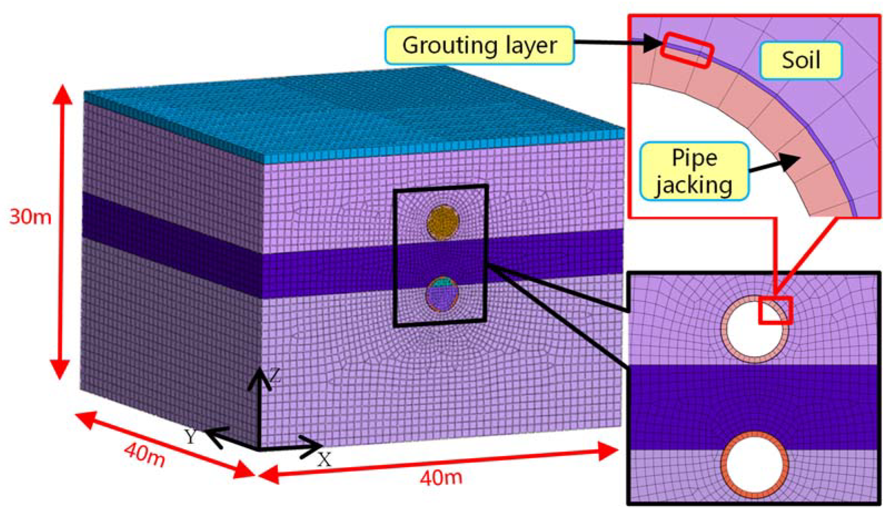
4.1. Model Establishment
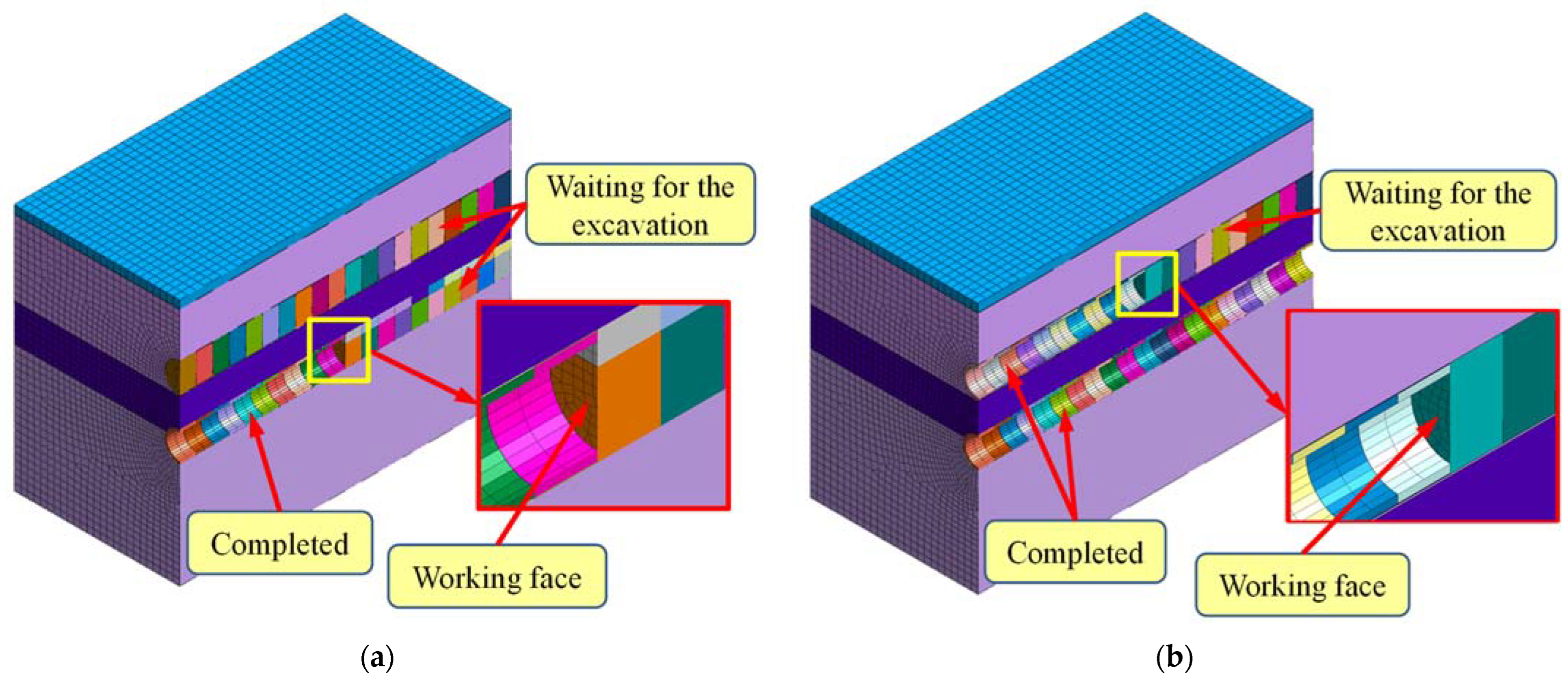
4.2. Construction Process Simulation Method
4.3. Constitutive Model and Calculation Parameters
5. Analysis of Numerical Simulation Results
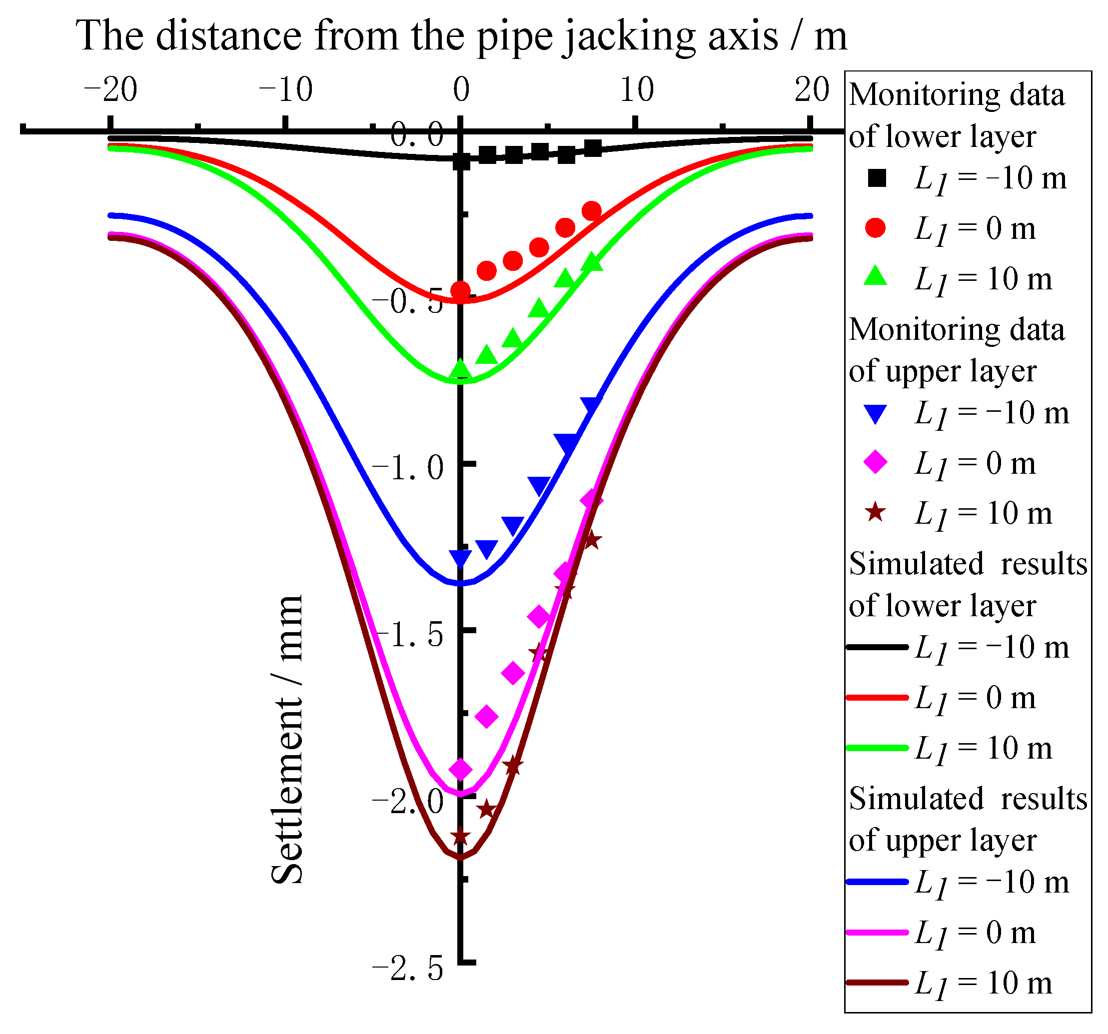
5.1. Analysis of Ground Settlement
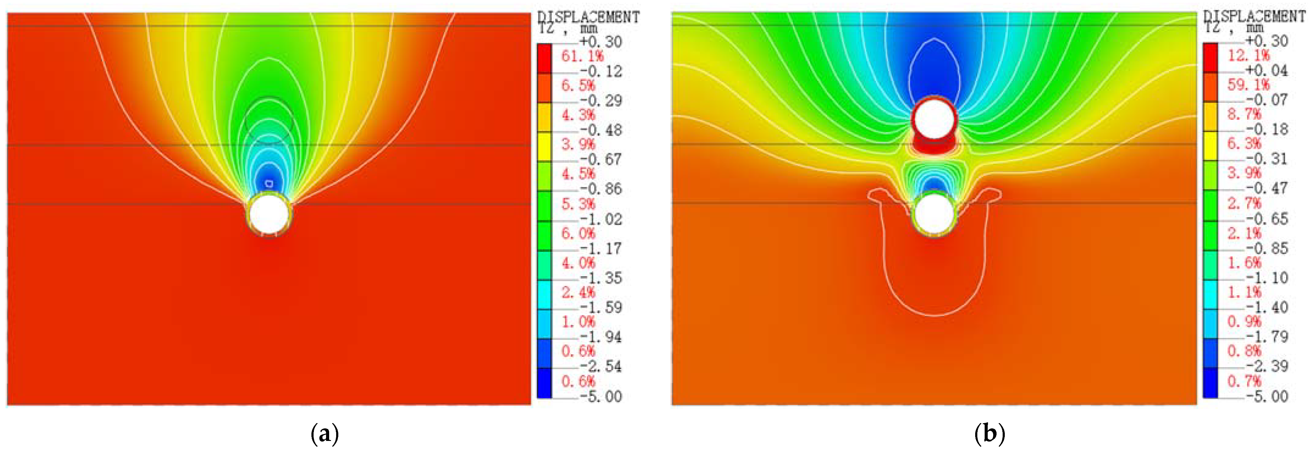
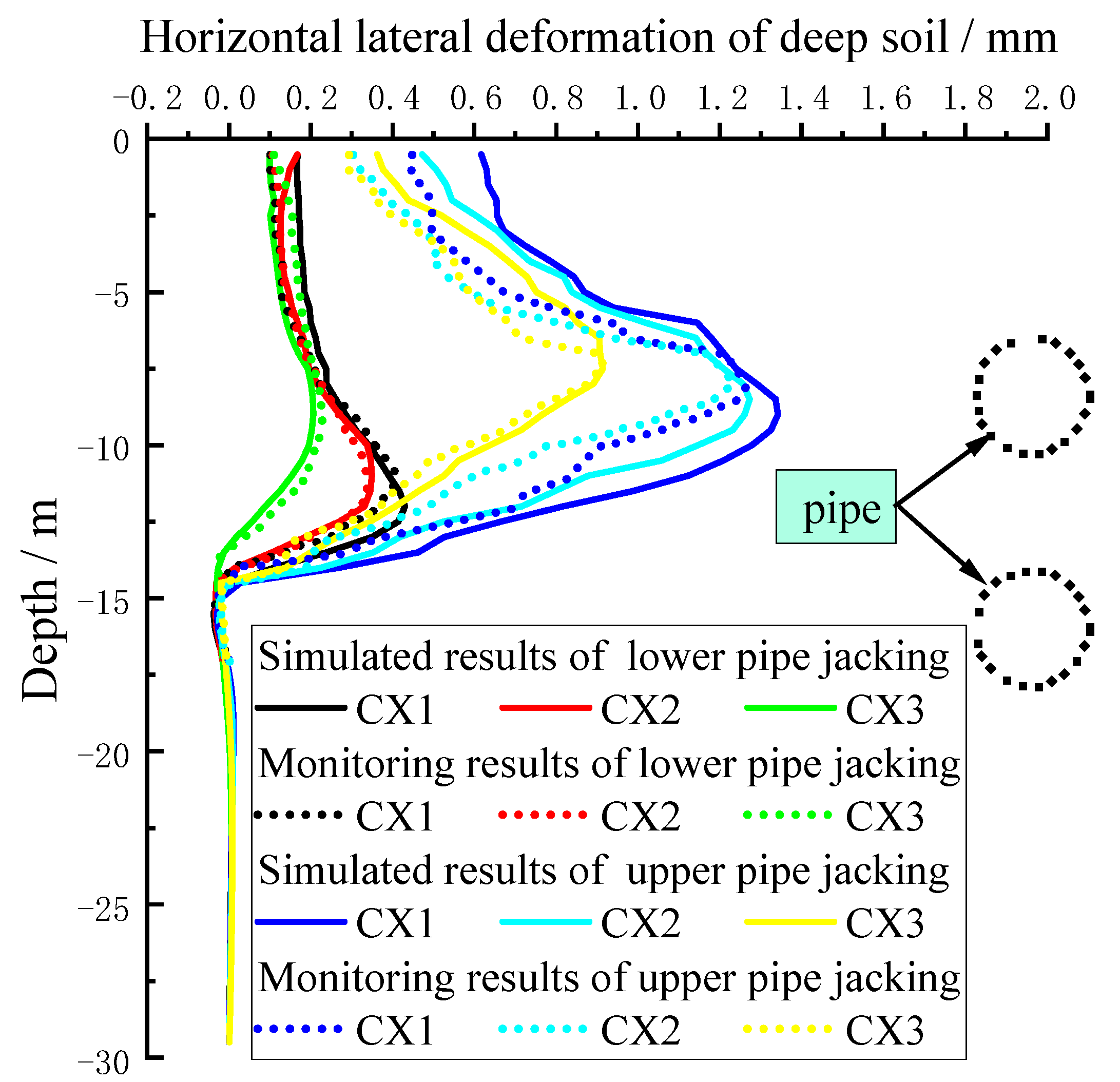
5.2. Analysis of Horizontal Lateral Displacement
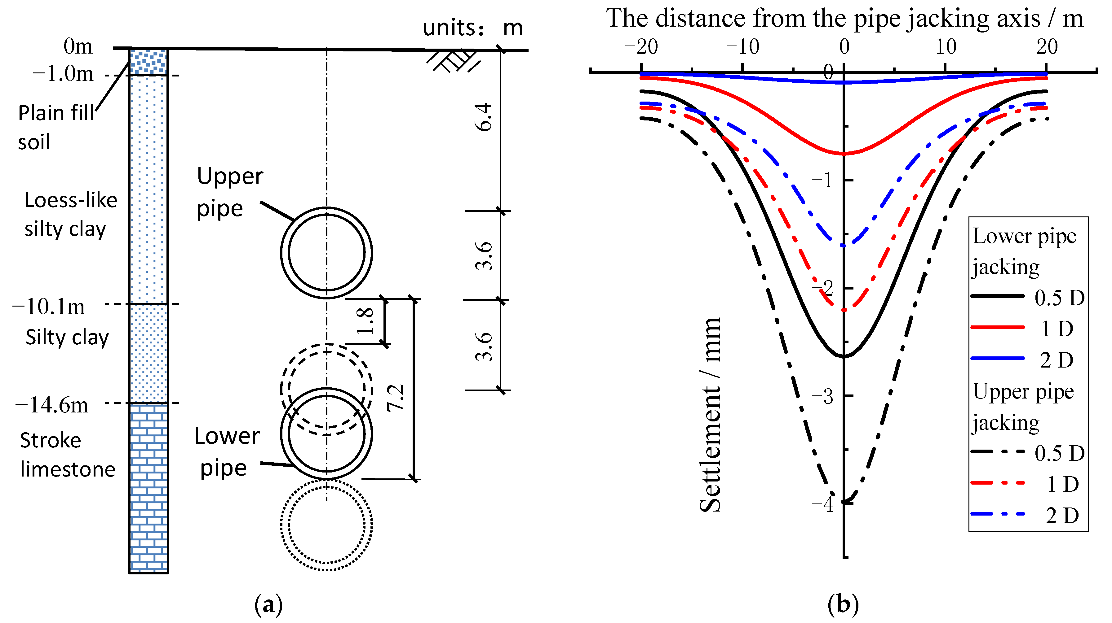
5.3. Influence Analysis of Vertical Spacing between Pipes
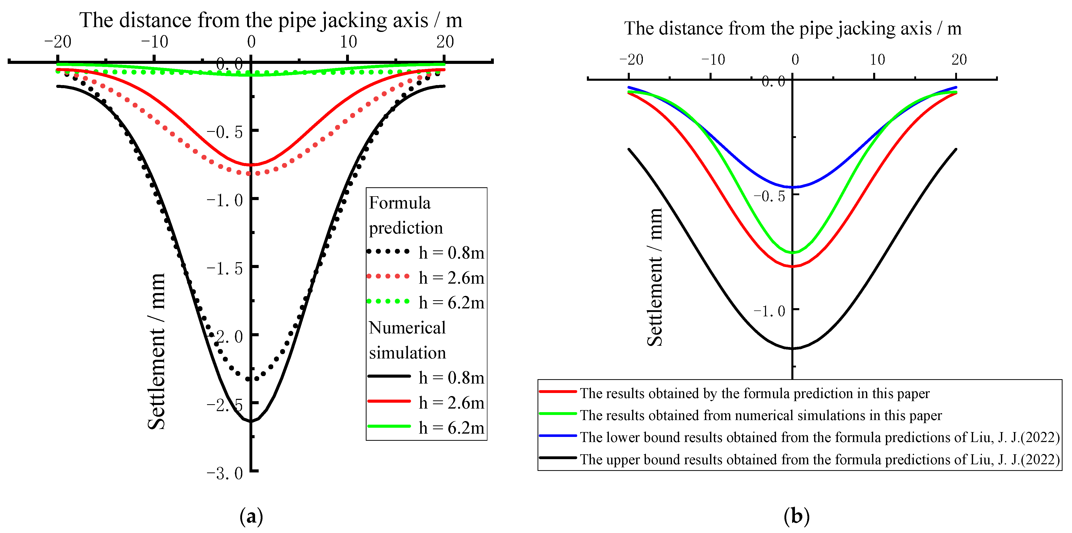
5.4. Ground Settlement Prediction for Pipe Jacking in the Soil-Rock Composite Stratum
6. Conclusions
- (1)
- The cumulative settlement of the pipe jacking machine before reaching the monitoring section accounts for about 60–70%, and 30–40% settlement can still be generated when the pipe jacking machine is far away from the monitoring section.
- (2)
- The maximum transverse and longitudinal ground settlements caused by the upper pipe are about three times those of the lower pipe. The maximum horizontal lateral displacement of the upper pipe jacking is about 3.3 times the lower pipe jacking construction.
- (3)
- In the construction of two-layer pipe jacking, total ground settlement increases with the reduction of vertical clear spacing between the upper and lower pipe. When the vertical clear spacing increased from half of the pipe diameter to 2.0 times pipe diameter, the total ground settlement is reduced by 75%.
- (4)
- The peck formula, which is used to estimate the lateral land subsidence distribution by tunnel construction, is modified to make it more applicable in the soil–rock composite stratum to calculate the ground settlement induced by pipe jacking.
Author Contributions
Funding
Institutional Review Board Statement
Informed Consent Statement
Data Availability Statement
Acknowledgments
Conflicts of Interest
References
- Song, Z.P.; Mao, J.C.; Tian, X.X.; Zhang, Y.W.; Wang, J.B. Optimization analysis of controlled blasting for passing through houses at close range in super-large section tunnels. Shock. Vib. 2019, 2019, 1941436. [Google Scholar] [CrossRef] [Green Version]
- Song, Z.P.; Shi, G.L.; Wang, J.B.; Wei, H.M.; Wang, T.; Zhou, G.N. Research on management and application of tunnel engineering based on BIM technology. J. Civ. Eng. Manag. 2019, 25, 785–797. [Google Scholar] [CrossRef]
- Tian, X.X.; Song, Z.P.; Wang, J.B. Study on the propagation law of tunnel blasting vibration in stratum and blasting vibration reduction technology. Soil Dyn. Earthq. Eng. 2019, 126, 105813. [Google Scholar] [CrossRef]
- Zhang, Y.W.; Weng, X.L.; Song, Z.P.; Sun, Y.F. Modeling of loess soaking induced impacts on metro tunnel using water soaking system in centrifuge. Geofluids 2019, 2019, 5487952. [Google Scholar] [CrossRef] [Green Version]
- Elbaz, K.; Shen, S.L.; Cheng, W.C.; Arulrajah, A.; Shirlaw, J.N. Cutter-disc consumption during earth pressure balance tunnelling in mixed strata. Proc. Inst. Civ. Eng.-Geotech. Eng. 2018, 171, 363–376. [Google Scholar] [CrossRef]
- Shou, K.; Yen, J.; Liu, M. On the frictional property of lubricants and its impact on jacking force and soil-pipe interaction of pipe-jacking. Tunn. Undergr. Space Technol. 2010, 25, 469–477. [Google Scholar] [CrossRef]
- Peck, R.B. Deep excavations and tunneling in soft ground. In Proceedings of the 7th ICSMFE, International Conference on Soil Mechanics and Foundation Engineering, Mexico City, Mexico, 29 August 1969; Balkema: Rotterdam, The Netherlands, 1969. [Google Scholar]
- Fang, Y.G.; Mo, H.H.; Zhang, C.Y. Theoretic and testing analysis of soil deformation in the area of disturbance caused by pipe-jacking. Chin. J. Rock Mech. Eng. 2003, 22, 601–605. [Google Scholar]
- Tang, J.; Li, S.C.; Zhu, Y.F. Measurement and Analysis of Settlement Induced by Rectangular Pipe Jacking in Silt Stratum. Adv. Mater. Sci. Eng. 2021, 2021, 8347227. [Google Scholar] [CrossRef]
- Bing, F.J.; Wang, X.; Xi, N.; Fang, L. 3D numerical simulation of pipe jacking and its soil applicability study. Chin. J. Undergr. Space Eng. 2011, 6, 1209–1215. [Google Scholar]
- Ren, D.J.; Xu, Y.S.; Shen, J.S.; Zhou, A.N.; Arulrajah, A. Prediction of ground deformation during pipe-jacking considering multiple factors. Appl. Sci. 2018, 8, 1051. [Google Scholar] [CrossRef] [Green Version]
- Wei, G.; Xu, R.Q.; Tu, W. Testing study and analysis on soil disturbance induced by pipe jacking construction. Chin. J. Rock Mech. Eng. 2004, 23, 476–482. [Google Scholar]
- Yu, J.F. Study on the Deformation of Earth’s Surface Induced by Pipe Jacking Construction. Master’s Thesis, Guangzhou University, Guangzhou, China, 2006. [Google Scholar]
- Jing, L.; Yuan, J.Y.; Yuan, Y. Ground loss parameter and soil deformation in pipe jacking. Rock Soil Mech. 2013, 34, 173–178. [Google Scholar]
- Huang, H.W.; Hu, X. 3D numerical analysis on construction mechanics effect of pipe-jacking. Chin. J. Rock Mech. Eng. 2003, 22, 400–406. [Google Scholar]
- Niu, Z.L.; Cheng, Y.; Zhang, Y.W.; Song, Z.P.; Yang, G.Y.; Li, H. A New Method for Predicting Ground Settlement Induced by Pipe Jacking Construction. Math. Probl. Eng. 2020, 2020, 1681347. [Google Scholar] [CrossRef]
- Qi, W.C.; Wang, L.H.; Zhou, S.Y.; Kang, Y.L.; Zhang, Q. Total loads modeling and geological adaptability analysis for mixed soil-rock tunnel boring machines. Undergr. Space 2022, 7, 337–351. [Google Scholar] [CrossRef]
- Yang, J.H.; Chen, W.B.; Zhang, L.; Xu, X.C.; Cheng, L.Y. Research on varying regularity of soil vertical deformation caused by the construction of two-layer jacking-pipe. Sci. Technol. Eng. 2014, 14, 274–279. [Google Scholar]
- An, G.F.; Wang, T.; Si, H.F.; Liu, T.J. Influence of construction sequence and different types of pipes on ground surface settlement caused by the construction of two-layer jacking-pipes. Mod. Tunn. Technol. 2019, 56, 119–126. [Google Scholar]
- Yu, J.; Gong, X.N. Numerical analysis of surface settlement control considering pipe jacking construction process. Chin. J. Rock Mech. Eng. 2014, 33, 2605–2610. [Google Scholar]
- Yang, C.S.; Mo, H.H.; Chen, J.S.; Li, Y.D.; Hou, M.X. Influence of the Approaching Construction of Underlying Shield Tunnels on Overlying Metro Tunnels. Mod. Tunn. Technol. 2015, 52, 145–151. [Google Scholar]
- Han, X.; Li, N.; Standing, J.R. An Adaptability Study of Gaussian Equation Applied to Predicting Ground Settlements Induced by Tunelling in China. Rock Soil Mech. 2007, 28, 23–28. [Google Scholar]
- Xie, D.W.; Ge, S.P.; Ding, W.Q.; Ouyang, W.B. Soil Mass Deformation Induced by Shield Tunnel Construction. Mod. Tunn. Technol. 2017, 54, 61–69. [Google Scholar]
- Zhang, Y.; Yin, Z.Z.; Xu, Y.F. Analysis on Three-Dimensional Ground Surface Deformations Due to Shield Tunnel. Chin. J. Rock Mech. Eng. 2002, 21, 388–392. [Google Scholar]
- Hu, C.M.; Feng, C.; Mei, Y. Modifying of Peck’s settlement calculation formula related to metro tunnel construction in Xi’an water-rich sand. Chin. J. Undergr. Space Eng. 2018, 14, 176–181. [Google Scholar]
- Lu, L.H.; Sun, J.C.; Zhou, G.F. Research on the surface deformation prediction for curved shield construction in clay stratum. J. Railw. Eng. Soc. 2018, 35, 99–105. [Google Scholar]
- Liu, J.J.; Liu, J.W.; Ren, X.M.; Jia, N. Modification of Peck formula for ground settlement caused by shield tunneling in soil-rock composite stratum. J. Henan Polytech. Univ. (Nat. Sci.) 2022, 41, 171–177. [Google Scholar]


| Soil Layer Classification | E/MPa | μ | γ (kN/m3) | c/kPa | /° | |
|---|---|---|---|---|---|---|
| Plain fill soil | 13.5 | 0.35 | 18 | 8 | 10 | 5.81 |
| Loess-like silty clay | 18 | 0.35 | 25 | 15 | 18 | 6.39 |
| Silty clay | 18.9 | 0.33 | 19.6 | 30 | 16 | 7 |
| Stroke limestone | 500 | 0.27 | 23 | 55 | 32 | 1170 |
| Grouting layer | 10 | 0.38 | 15 | 5 | 5 | 2.29 |
| Tube segment | 3000 | 0.17 | 24 | - | - | - |
| Area | m | ||||
|---|---|---|---|---|---|
| Beijing | β | β | (0.5–1.0) | (2–4) | 0.4–0.7 |
| 0.5 D/mm | 1 D/mm | 2 D/mm | |
|---|---|---|---|
| Lower pipe jacking (SL) | 2.64 | 0.75 | 0.09 |
| Upper pipe jacking (SU) | 4.00 | 2.21 | 1.59 |
| Total ground settlement (ST) | 6.64 | 2.96 | 1.68 |
| SL/ST | 39.8% | 25.3% | 5.4% |
Publisher’s Note: MDPI stays neutral with regard to jurisdictional claims in published maps and institutional affiliations. |
© 2022 by the authors. Licensee MDPI, Basel, Switzerland. This article is an open access article distributed under the terms and conditions of the Creative Commons Attribution (CC BY) license (https://creativecommons.org/licenses/by/4.0/).
Share and Cite
Shao, G.; Yang, N.; Han, J. Study on the Deformation Induced by Vertical Two-Layer Large Diameter Pipe-Jacking in the Soil-Rock Composite Stratum. Appl. Sci. 2022, 12, 12780. https://doi.org/10.3390/app122412780
Shao G, Yang N, Han J. Study on the Deformation Induced by Vertical Two-Layer Large Diameter Pipe-Jacking in the Soil-Rock Composite Stratum. Applied Sciences. 2022; 12(24):12780. https://doi.org/10.3390/app122412780
Chicago/Turabian StyleShao, Guangbiao, Nan Yang, and Jianyong Han. 2022. "Study on the Deformation Induced by Vertical Two-Layer Large Diameter Pipe-Jacking in the Soil-Rock Composite Stratum" Applied Sciences 12, no. 24: 12780. https://doi.org/10.3390/app122412780