Article

Linear Active Disturbance Rejection Control-Based Diagonal Recurrent Neural Network for Radar Position Servo Systems with Dead Zone and Friction

College of Automation and Electronic Engineering, Qingdao University of Science and Technology, Qingdao 266061, China
*
Author to whom correspondence should be addressed.
Appl. Sci. 2022, 12(24), 12839; https://doi.org/10.3390/app122412839
Submission received: 23 November 2022 / Revised: 6 December 2022 / Accepted: 12 December 2022 / Published: 14 December 2022

Abstract

:
This paper proposes a control scheme for the radar position servo system facing dead zone and friction nonlinearities. The controller consists of the linear active disturbance rejection controller (LADRC) and diagonal recurrent neural network (DRNN). The LADRC is designed to estimate in real time and compensate for the disturbance with vast matched and mismatched uncertainties, including the internal dead zone and friction nonlinearities and external noise disturbance. The DRNN is introduced to optimize the parameters in the linear state error feedback (LSEF) of the LADRC in real time and estimate the model information, namely Jacobian information, of the plant on-line. In addition, considering the Cauchy distribution, an adaptive tracking differentiator (ATD) is designed in order to manage the contradiction between filtering performance and tracking speed, which is introduced to the LADRC. Another novel idea is that the back propagation neuron network (BPNN) is also introduced to tune the parameters of the LADRC, just as in the DRNN, and the comparison results show that the DRNN is more suitable for high precision control due to its feedback structure compared with the static BPNN. Moreover, the regular controller performances and robust performance of the proposed control approach are verified based on the radar position servo system by MATLAB simulations.

1. Introduction

The position servo system is an important part of airborne radar, of which the control performance directly decides the real time target detection and stability performance of airborne radar [1,2,3]. The servo mechanism is susceptible to the influence of external interference such as the attitude of the carrier, vibration, airflow and the follow-up of the target position when the radar is tracking for the target. Therefore, the radar position servo system is supposed to have high static stability, dynamic response capability and strong resistance disturbance capability [4,5]. Traditional PID control is currently widely used in radar position servo systems, it has a tracking lag and is easily affected by external disturbances since dead zone and friction nonlinearities widely exist in radar servo systems [6] so it cannot meet high precision control requirements. Therefore, it is of great practical significance and application value to implement non-linear compensation methods such as external interference and internal clearance, change the problem of tracking hysteresis, improve the stability of the system during operation, and ensure that the system operates in the optimal state.
A.
Literature Review
The dead zone is a non-smooth nonlinear phenomenon, which often exists in hydraulic servomechanisms, servomotors, etc., in industrial systems [7]. The dead zone directly affects the control precision of the system and even makes the system unstable [8]. According to [9], an adaptive robust control scheme with dead zone compensation was proposed, which was applied to synthesize the system controller for both accurate parameter estimation and guaranteed robust performance to various uncertainties. Ref. [10] investigated the output tracking problem for uncertain nonlinear systems in the presence of actuator dead zone nonlinearity with piecewise time-varying parameters. Technically, a better enhancement of the system performance was achieved by a modified tuning functions approach. In [11], a fuzzy logic dead zone compensator was adopted based on the estimation of the dead zone width that was obtained by using an adaptive method to manage the non-symmetric dead zone input phenomenon. In addition, friction nonlinearity inevitably exists in those contact-type mechanisms, which usually results in sliding and crawling of the mechanism, and greatly affects the stability of the system [12]. It is usually laborious to establish a mathematical model of friction nonlinearity in a practical system because of its special nonlinearity. The Stribeck friction model [13] is widely applied in practical system modeling studies, which can reflect the relationship between relative speed and friction coefficient well, and can describe the friction phenomena well such as static friction, the Stribeck effect and so on. Moreover, it is convenient for identifying the parameters of the Stribeck friction model. Ref. [13] drew the conclusion through a series of experiments that the friction force changed continuously during the process from static to moving. At low speed, the friction torque decreased with the increase in angular velocity. Concerning the friction compensation of the control system, work [14] designed an adaptive steering control system with a friction compensator for an unmanned surface vehicle (USV), where the radial basis function (RBF) neural network was integrated to approximate the friction disturbance online. An adaptive extended state observer (AESO) based robust controller was proposed in [15] for precise position tracking control of a magnetic rodless cylinder with strong static friction, where the AESO with dynamic gains was utilized to estimate the static friction and nonlinearities. There is no doubt that the combination of the dead zone and friction nonlinearity brings greater challenges to designing the controller for implementing the high-precision control of the radar system.
An active disturbance rejection controller (ADRC) is an excellent tool for total disturbance compensation, which only requires minimal model information and can sufficiently eliminate the model uncertainties as well as unknown disturbances. The most important aspect is the design of the extended state observer (ESO), which can estimate the total disturbance of the system in real time. Han in [16] expounded on the development from PID to ADRC in detail. Although ADRC has high feedback efficiency and tracking accuracy due to its nonlinear mechanism, it is not suitable for practical engineering applications. In [17,18], the ADRC is linearized, which greatly simplifies the parameter adjustment method of the ADRC and makes it more suitable for practical engineering. Aiming at the weak anti-interference ability of a photovoltaic grid connected inverter management scheme, an improved LADRC controller was proposed by Refs. [19,20], which optimizes the parameters by observing and estimating the total interference by linear extended state observer (LESO), compensating the interference by the PD controller and adding adaption. The results showed that the improved method has better rapidity and robustness. The objective of [21] was to design a vibration isolation platform for payloads on spacecraft with a robust, wide bandwidth and multi-degree-of-freedom (MDOF), where the LADRC algorithm was utilized for the active control. An improved LADRC based on proportional differentiation was proposed in [22] in order to improve the control performance of the grid-side inverter of the energy storage system, where LESO was improved to a proportional differentiation link. In [23], a novel compound control scheme that combined the advantages of partial feedback linearization (PFL) and LADRC was presented for a pressurized water reactor (PWR), where the controller parameters were optimized by tuning bandwidth. Ref. [24] proposed a cascade control strategy based on the LADRC for a DC/DC boost converter, solving the problem of unstable output voltage of the boost converter. Motivated by the salient feature in model independence, the LADRC is employed for the tracking control of the radar position servo system to mitigate the undesirable impact of the internal nonlinear dynamics and unknown external disturbances.
B.
Contributions Statement
Inspired by the above research, a linear active disturbance rejection control (LADRC) scheme based on the diagonal recurrent neural network (DRNN) [25,26,27,28] has been designed for adaptive control of the radar position servo system facing dead zone and friction nonlinearities in this paper. For one thing, the LADRC is used for real-time estimates and compensates for disturbance with unknown nondeterminacies. Moreover, an adaptive tracking differentiator (ATD) was also designed and introduced into the LADRC in order to eliminate the peak value of the control signal and reduce the spike impact of the control signal on the actuator. For another thing, DRNN is utilized to identify the sensitivity of the plant with respect to its input on-line and optimize parameters of the LSEF in the LADRC in real time. Moreover, the compound controller DRNN-LADRC can accomplish high accuracy control; additionally, it can also improve the resistance interference ability of the controller, forming an adaptive form to attain the optimal control result. The effectiveness of this method was proven by MATLAB simulation.
The main contributions of this paper are summarized as follows:
a. It is well known that increasing the speed factor in the traditional tracking differentiator (TD) will reduce its filtering effect, reproduce the noise of the input signal in the output signal, and produce the peak error of the output differential signal [29]. Then, it is necessary to increase the filtering factor, but this will increase the lag of the system output. The ATD, which can adaptively adjust the speed factor and filter factor according to the change rate of the input signal, is designed in this paper to deal with the contradiction between filtering performance and tracking speed.
b. The LADRC has self-learning ability and better control performances by introducing the DRNN to tune the parameters of the LSEF in real time, adapting well to the changes of the plant such as parameter and disturbance changes, etc. Moreover, it has higher tracking accuracy for the radar position servo system than the LADRC based on the back propagation neural network (BPNN-LADRC) [30], since DRNN is found to be more suitable to identify dynamic nonlinear systems than those static neural networks such as BPNN, radical basis function neural network (RBFNN) and so on, that contains internal feedback loops which can store the plant information and utilize it at the later stage [25,26].
c. The LADRC containing the proposed ATD consumes less energy than the LADRC [22,31]; the peak value of the control signal is removed, thus effectively suppressing the influence on the final control element, and it is of great significance in practical application.
d. In the whole control system, only one parameter (controller bandwidth, denoted as w 0 ) needs to be adjusted; other arguments are automatically adjusted by the algorithm proposed in this paper.
C.
Paper Organization
The rest of this paper is organized as follows. In Section 2, the radar position servo model with dead zone and friction nonlinearities is introduced. In Section 3, the design of the proposed compound controller DRNN-LADRC is specified. The controller effects with regard to the ATD performance, tracking the performance of the proposed controller and robust performance are verified with several case studies in Section 4. Finally, Section 5 concludes this paper.

2. Radar Position Servo System Modeling

A precise radar servo system generally has two branches, namely azimuth and pitch, which are both driven by the motor. This paper takes the azimuth axis of the radar position servo system as an example to verify the performance of the composite controller. Taking the antenna as the total load in this model, the following dynamic equations of the radar servo system are established and the model block diagram of the radar position servo system is shown in Figure 1.
Where u c is the input voltage of the motor, R a is the armature resistance, L a is the armature inductance [31], K T is the motor torque coefficient, B is the elastic coefficient, F is the viscous damping coefficient, K P is the power magnification, T L is the load torque, K E is the back electromotive force of the motor, J is the system moment of inertia, θ is the output pointing angle of the load antenna, S is the complex frequency domain, and 1 R a + L a s and 1 J s + F are the output formulas of motor voltage after Laplace transform.
Ignoring the influence of the elastic moment on the system, the relationship between u c and θ can be obtained as follows:
θ ( s ) = K T K P U C ( s ) ( L a s + R a ) T L ( s ) s ( J s + F ) ( L a s + R a ) + K E K T
Since the induction L a of the motor utilized in this system is very small, the influence of L a on the system can be ignored and the system (1) can be rewritten as:
J R a θ ¨ + ( F R a + K E K T ) θ ˙ = K T K P u c R a T L
When the servo system drives the antenna to track the target, it is mainly affected by the unbalanced torque and inertia moment; thus, the load torque equation can be obtained as follows:
T L = m θ ¨ r + J L θ ¨
where m is the weight of the load antenna, r is the eccentric disturbance of the load antenna, and J L is the load moment of inertia.
Substitute (3) into (2):
R a ( J + m r + J L ) θ ¨ + ( F R a + K E K T ) θ ˙ = K T K P u c
Then (4) can also be written in the following state space equation as
x ˙ 1 = x 2 x ˙ 2 = F R a + K E K T R a ( J + m r + J L ) x 2 + K T K P R a ( J + m r + J L ) u y = x 1
where θ = x 1 , θ ˙ = w = x 2 and w is the mechanical angular velocity.
Since the backlash-like nonlinearities such as dead zone and friction nonlinearity, etc., exist in practical servo systems, then a dead zone function with non-smooth nonlinearity and the Stribeck friction model [11,32] are both introduced into (5). The dead zone Φ γ ( t ) , d function is assumed and defined as
ϕ γ ( t ) , d = s i g n ψ ( t ) ψ ( t ) d 2 1 f s g γ ( t ) , d
where ψ ( t ) = γ ( t ) γ ( t ) , f s g γ ( t ) , d = s i g n γ ( t ) + d s i g n γ ( t ) d 2 , γ ( t ) is the input of dead zone, d is the unknown constant.
Then, the Stribeck friction model, which reflects the effect that the friction torque decreases with the increase in angular velocity, is described as
Γ ( x 2 ) = F C + ( F S F C ) e γ x 2 s i g n ( x 2 ) + B x 2
where F c is Coulomb friction, F s is the maximum static friction, B is the viscous friction coefficient, and γ is the empirical constant.
Considering the dead zone and friction nonlinearities inevitably involved in the system, the system can be described as
x ˙ 1 = x 2 x ˙ 2 = F R a + K E K T R a ( J + m r + J L ) x 2 + ϕ γ ( t ) , d + Γ ( x 2 ) + K T K P R a ( J + m r + J L ) u y = x 1

3. Compound Controller DRNN-LADRC Design

3.1. Preliminary to LADRC

The core idea of the LADRC is that LESO estimates the total disturbance in real time, and then uses the control law to compensate for the total disturbance. As for the system (8), define Λ t , x 2 , d = F R a + K E K T R a J + m r + J L x 2 + Φ γ ( t ) , d + Γ x 2 , b 0 = K T K P R a ( J + m r + J L ) and Λ ˙ t , x 2 , d = q . Then, the extended state variable is defined as x 3 = Λ t , x 2 , d in order to design the LESO. Thus, system (8) can be rewritten as
X ˙ = A X + B u + S q y = C X
where A = 0 1 0 0 0 1 0 0 0 , B = 0 b 0 0 , C = 1 0 0 , S = 0 0 1 T ,   X = x 1 x 2 x 3 T can be observed through the following LESO:
ζ ˙ = A ζ + B u + H ( y y ^ ) y ^ = C ζ
where ζ = ζ 1 ζ 2 ζ 3 T , H = η 1 η 2 η 3 T is the observer gain vector simplified by its characteristic equation, which is given as follows:
λ 0 ( s ) = s 3 + η 1 s 2 + η 2 s + η 3 = ( s + ω 0 ) 3
where w 0 is the observer bandwidth that means H = 3 w 0 3 w 0 2 w 0 3 T . It is well known that the larger w 0 , the better the tracking effect [33]. However, oversized w 0 will also reduce the immunity. Thus, w 0 is not supposed to be designed too large in practical applications.
The resulting values ζ 1 = y ^ , ζ 2 = y ˙ ^ and ζ 3 = Λ ˙ t , x 2 , d can all be obtained through the LESO, and LSEF [23] is designed as follows:
u 0 = k p ( v d ζ 1 ) k d ζ 2 u = u 0 ζ 3 b 0
where v d is the desired signal, optimizing two key parameters k p and k d can make the system more stable. In this paper, the neural network is introduced to optimize k p and k d in real time.
Assumption 1.
The expected signal  v d ( t ) is glossy and bounded, so that  v d ( t ) V d holds, is a known constant.
Assumption 2.
The total disturbance  Λ ( t , x 2 , d ) is bounded, so that  Λ ( t , x 2 , d Λ d holds,  Λ d is a known constant.

3.2. Proposed Adaptive Tracking Differentiator Design

Remark 1.
As the input signal change rate increases, the output signal will have an obvious tracking lag in the traditional TD. The elimination of the lag is achieved by increasing the speed factor, but it will reduce the filtering effect of the TD and reproduce the noise of the input signal in the output differential signal. At the same time, a spike error of the output differential signal will exist. The ATD, which can adaptively adjust the speed factor and filter factor according to the change rate of the input signal, is designed in this paper, to manage the contradiction between filtering performance and tracking speed. Moreover, the LADRC introducing the proposed ATD will consume less energy than the LADRC [34], eliminating the peak value of the control signal and reducing the impact of the control effect on the final controlling element.
The traditional TD [34] is described as follows:
v 1 ( k + 1 ) = v 1 ( k ) + h v 2 ( k ) v 2 ( k + 1 ) = v 2 ( k ) + h f s t v 1 ( k ) v d ( k ) , v 2 ( k ) , κ , h 0
where v d ( k ) is the desired trajectory, h is the sampling step, κ is the speed factor, h 0 is the filter factor, v 1 ( k ) and v 2 ( k ) track v d ( k ) and v ˙ d ( k ) , respectively, and f s t ( · ) is a nonlinear composite function, which can be expressed as
f s t ( z 1 , z 2 , κ , h ) = κ a l , a l κ sgn ( a ) , a > l
a = z 2 + a 0 l 2 sgn ( f ) , f > l 0 z 2 + f h , f l 0
l = κ h , l 0 = l h , a 0 = l 2 + 8 κ f , f = z 1 + h z 2
In order to manage the above problem of the traditional TD, it is necessary to design a continuous and bounded function as the adaptive control function of the speed factor κ , which can increase rapidly with the increase in the differential signal. At the same time, the filter factor h 0 is supposed to be taken large when the differential signal is around zero in order to eliminate spike error.
The Cauchy distribution [35] is considered, and its probability density function f ( x ) and cumulative distribution function F ( x ) are given as
f ( x ) = 1 π σ 1 + x x 0 σ 2
F ( x ) = 1 π arctan x x 0 σ + 1 2
where σ is the scale factor, and x 0 is the position factor.
It is well known that the position of two function curves can be adjusted by tuning x 0 ; the height and width of the curves can be adjusted by tuning σ . Additionally, the value of f ( x ) is large enough when x x 0 , F ( x ) is a bounded function that increases rapidly with the increase of x . Then, F ( x ) and f ( x ) are utilized to design the adaptive function of κ and h 0 by setting x 0 = 0 , respectively, which are described as
κ ( v 2 ) = K 1 π arctan v 2 σ 1 + 1 2 + L
where K is the variety range of κ , and L is the initial value of κ .
h 0 ( v 2 ) = 1 π σ 2 1 + v 2 2 σ 2
Therefore, (13) can be rewritten as
v 1 ( k + 1 ) = v 1 ( k ) + h v 2 ( k ) v 2 ( k + 1 ) = v 2 ( k ) + h f s t v 1 ( k ) v d ( k ) , v 2 ( k ) , κ ( v 2 ) , h 0 ( v 2 )
After introducing (18) into the LADRC, LSEF (12) can be rewritten as
e 1 = v 1 ζ 1 , e 2 = v 2 ζ 2 u 0 = k p e 1 + k d e 2 u = u 0 ζ 3 b 0

3.3. Proposed Improved LADRC Design

Remark 2.
In most cases, k p and k d as the gains of the PD controller are acquired by an experiential or trial-and-error approach [36]. Moreover,  k p and k d may be simplified by placing both poles for the closed loop equivalent system at the same critically damped location so that people need only consider adjusting the controller bandwidth [35]. In this paper, the DRNN is introduced to estimate the sensitivity of the plant with respect to its input on-line and tune the  k p and k d in real time, making the LADRC have self-learning ability and adapt well to the changes of the radar servo system.
(1) DRNN-based LADRC Design
The DRNN is better suited for estimating the system model than the static feed-forward networks, and the DRNN has the ability to manage time-varying input or output through its natural temporal operation since the signals within the hidden layer are the feedback signals from the output layer and have different time delays [28]. Additionally, the structure of the DRNN is shown in Figure 2, where the dashed part denotes the diagonal weights that transmit the unit delay output of the recurrent neuron as an input to the same recurrent neuron. The DRNN has a three-layer structure, namely the input layer, the hidden layer and the output layer. The input weight vector is denoted by Q I D R = w 11 I , w 12 I , , w ε λ I T , where ε denotes the number of input neurons in the input layer, and λ denotes the number of recurrent neurons in the hidden layer. Additionally, the diagonal weight vector and output weight vector are expressed by Q D D R = w 1 D , w 2 D , , w λ D T , and Q O D R = w 1 O , w 2 O , , w λ O T . The external input vector is denoted by I ( k ) = I 1 ( k ) , I 2 ( k ) , , I ε ( k ) T . The output of any λ t h recurrent neuron is described by Ψ λ ( k ) , which is evaluated as
Ψ λ ( k ) = f a c t N λ ( k )
where f a c t ( · ) is an activation function, which is expressed by f a c t ( x ) = e x e x e x + e x ; O λ ( k ) is the input of any λ t h recurrent neuron, which is evaluated as
O λ ( k ) = w λ D Ψ λ ( k 1 ) + ε w ε λ I I ε ( k )
There is only one neuron in the output layer, and its activation function is linear so there is no restriction on its value. Thus, the output of the DRNN can be obtained as
G D R ( k ) = λ w λ O Ψ λ ( k )
Then, an error function for a training cycle can be defined as
E D = 1 2 y ( k ) y D ( k ) 2 = 1 2 e d 2 ( k )
where y ( k ) is the output of the plant, y D ( k ) = Y D ( k ) .
The gradient of error function (23) with respect to an arbitrary weight vector simply becomes
E D Q = e d ( k ) y D ( k ) Q = e d ( k ) G D R ( k ) Q
where Q represents Q O D R , Q D D R or Q I D R .
Lemma 1
[37]. Given the DRNN shown in Figure 2 and described by (20)–(22), the output gradients with respect to output, recurrent and input weights, respectively, were given by
G D R ( k ) w λ O = Ψ λ ( k )
G D R ( k ) w λ D = w λ O G λ ( k )
G D R ( k ) w ε λ I = w λ O S ε λ ( k )
where L λ ( k ) = Ψ λ ( k ) w λ D , S ε λ ( k ) = Ψ λ ( k ) w ε λ I , which respectively satisfy
L λ ( k ) = f ˙ a c t O λ ( k ) Ψ λ ( k 1 ) + w λ D L λ ( k 1 )
S ε λ ( k ) = f ˙ a c t O λ ( k ) I ε ( k ) + w λ D S ε λ ( k 1 )
where f ˙ a c t O λ ( k ) = 1 + Ψ λ ( k ) 1 Ψ λ ( k ) 2 .
From (24), the negative gradient can be obtained as
E d Q = e d ( k ) G D R ( k ) Q
where the output gradients are given by (25)–(29).
Now, the steepest descent method is utilized to train weights and the updated role of the weights becomes
Q ( k + 1 ) = Q ( k ) + μ D E D Q + χ D Q ( k ) Q ( k 1 )
where μ D is the learning rate of the DRNN and χ D is the momentum factor of the DRNN.
Next, (19) can be discretized as
u ( k ) = k p e 1 ( k ) + k d e 2 ( k ) ζ 3 ( k ) b 0
where e 1 ( k ) = v 1 ( k ) ζ 1 ( k ) , e 2 ( k ) = v 2 ( k ) ζ 2 ( k ) , k p and k d are adjusted as follows.
An error function for adjusting parameters of the LSEF is defined as
E T ( k ) = 1 2 v d ( k ) y ( k ) 2 = 1 2 e t 2 ( k )
where v d ( k ) is the input desired signal.
In the same way, the error gradients with respect to k p ( k ) and k d ( k ) are given by
E T ( k ) k p ( k ) = e t ( k ) y ( k ) k p ( k ) = e t ( k ) y ( k ) u ( k ) u ( k ) k p ( k )
E T ( k ) k d ( k ) = e t ( k ) y ( k ) k d ( k ) = e t ( k ) y ( k ) u ( k ) u ( k ) k d ( k )
where y ( k ) u ( k ) G D R ( k ) u ( k ) is the Jacobian information of the plant, which represents the sensitivity of the plant with respect to its input. The sensitivity is unknown, which can be estimated by DRNN since the accurate mathematical model of the plant is usually unknown. In [38], the sensitivity is given as
G D R ( k ) u ( k ) = λ w λ O f ˙ a c t O λ ( k ) w ε λ I
And the gradients of (32) with respect to k p ( k ) and k d ( k ) can be obtained as
u ( k ) k p ( k ) = e 1 ( k )
u ( k ) k d ( k ) = e 2 ( k )
Substitute (37) and (38) in (34) and (35), respectively:
E T ( k ) k p ( k ) = e t ( k ) y ( k ) k p ( k ) = e t ( k ) y ( k ) u ( k ) u ( k ) k p ( k )
E T ( k ) k p ( k ) = e t ( k ) y ( k ) k d ( k ) = e t ( k ) y ( k ) u ( k ) e 2 ( k )
Therefore, the gradient descent algorithm can be utilized to optimize the parameters and the tuning role is given as
k ( k ) = k ( k 1 ) + μ E T ( k ) k ( k )
where k ( k ) is k p ( k ) or k d ( k ) , μ is the learning rate with respect to k p ( k ) or k d ( k ) .
According to (41), it can be considered that k p ( k ) and k d ( k ) can change with the change of system error, so as to achieve the best control effect.
The control target is to promise that the desired trajectory can be tracked with a small domain of the origin in presence of dead zone and friction disturbances. The scheme map of the compound controller DRNN-LADRC is given in Figure 3.
(2) System stability analysis
Since the discrete form can be converted to the continuous form, the convergence of LESO and the stability analysis of the whole system have been derived in the continuous form in this section.
Firstly, the convergence of LESO is analyzed.
Order, χ i t = x i t ζ i t , i = 1 , 2 , 3
i t = χ i t / w 0 i 1 , i = 1 , 2 , 3 , combining (4) and (5), the error equation of LESO estimation can be obtained:
· 1 t = η 1 w 0 0 1 + w 0 2 · 2 t = η 2 w 0 1 1 + w 0 3 · 3 t = η 3 w 0 2 1 + q w 0 2
Because η 1 = 3 w 0 , η 2 = 3 w 0 2 , η 3 = w 0 3 , then (42) can be expressed as
· t = w 0 M σ + N q w 0 2
Among them, M = 3 1 0 3 0 1 3 0 0 , N = 0 0 1 .
Theory 1.
Assuming q is bounded, then there is a positive number α i > 0 , limited time T > 0 , making  χ i t α i , i = 1 , 2 , 3 , t T > 0 , χ i t α i , i = 1 , 2 , 3 , t T > 0 .
Solve Equation (43) to get
t = e w 0 M t 0 + 0 t e w 0 M t τ N q w 0 2 d τ
Order:
G t = 0 t e w 0 M t τ N q w 0 2 d τ
Because q bounded, q E , E > 0 , then
G i t E w 0 3 M 1 N i + M 1 e w 0 A t N i
And because M 1 = 0 0 1 1 0 3 0 1 3 , then
M 1 N i = 1 , i = 1 3 , i = 2 , 3
Because A is a Hurwitz matrix, there is a finite time T > 0 , so that all t T , i , j = 1 , 2 , 3 have:
e w 0 M t i j 1 w 0 3 e w 0 M t N i 1 w 0 3
Set up M 1 = υ 11 υ 12 υ 13 υ 21 υ 22 υ 23 υ 31 υ 32 υ 33 , N 1 = ρ 11 ρ 12 ρ 13 ρ 21 ρ 22 ρ 23 ρ 31 ρ 32 ρ 33 , then
M 1 e w 0 M t N i = υ i 1 ρ 13 + υ i 2 ρ 23 + υ i 3 ρ 33 1 w 0 3 , i = 1 4 w 0 3 , i = 2 , 3
For simultaneous Equations (46), (47) and (49), Equation (46) can be written as
G i t 3 E w 0 3 + 4 E w 0 6
For all t T , i = 1 , 2 , 3 , order max 0 = 1 0 + 2 0 + 3 0 ,
e w 0 M t 0 i max 0 w 0 3
i t max 0 w 0 3 + 3 E w 0 3 + 4 E w 0 6
Order χ max 0 = χ 1 0 + χ 2 0 + χ 3 0 , in addition, according to i t = χ i t / w 0 i 1 , and according to Formulas (50)–(52)
χ i t max 0 w 0 3 + 3 E w 0 4 i + 4 E w 0 7 i = α i
Equation (53) shows that if the differential of the total disturbance is bounded, the prediction error of LESO is bounded, and when the w 0 increases, χ i t 0 .
Then, we analyze the stability of the whole control system. Consider the following:
V ˙ t = J V t + p t
Among them, V t = V 1 t , V 2 t , , V n t Τ R n , p t = p 1 t , p 2 t , , p n t T R n , J is n × n matrix.
Lemma 2.
If J is a Hurwitz matrix and lim t p t = 0 , then  lim t V t = 0 .
Theory 2.
If q is bounded, there is a constant w 0 > 0 , k p > 0 , k d > 0 to make the closed-loop system stable.
Definition 1.
v a = v ˜ 1 , v ˙ a = v ˜ 2 , v ¨ a = v ˜ 3 , δ 1 = v ˜ 1 x 1 , δ 2 = v ˜ 2 x 2 , δ 3 = v ˜ 3 x 3 , because χ i t = x i t ζ i t , i = 1 , 2 , 3 , Equation (12) can be written as
u = k p δ 1 + χ 1 + k d δ 2 + χ 2 x 3 χ 3 + v ˜ 3 / d
Because
δ · 1 = v ˜ ˙ 1 x ˙ 1 = v ˜ 2 x 2 = δ 2
δ · 2 = v ˜ ˙ 2 x ˙ 2 = v ˜ 2 x 3 + b 0 u = k p δ 1 k d δ 2 k p χ 1 k d χ 2 χ 3
Then
δ · t = Γ ˜ 1 δ t + Γ ˜ 2 χ t
Among them, Γ ˜ 1 = 0 1 k p k d , Γ ˜ 2 = 0 0 0 k p k d 1 .
According to Theory 1, χ i t χ max 0 w 0 3 + 3 E w 0 4 i + 4 E w 0 7 i , i = 1 , 2 , 3 , and when w 0 increases χ i t 0 , available lim t Γ ˜ 2 χ t = 0 , the size selection of k p and k d makes Γ ˜ 1 a Hurwitz matrix. Because the DRNN optimizes k p and k d , it must make k p > 0 , k d > 0 , in conclusion, according to Theory 1 and Lemma 1, the existence constant w 0 > 0 , k p > 0 , k d > 0 , make lim t δ i t = 0 , i = 1 , 2 and the closed loop system is stable.
(3) BPNN-based LADRC Design
Remark 3.
Along with [33], the BP algorithm is introduced to regulate the LSEF parameters of  k p  and  k d online to further enhance the robustness and adaptability of the LADRC in this paper, where the sensitivity of the plant with respect to its input  y ( k ) u ( k )  cannot be accurately calculated, and the sgn y ( k ) u ( k )  function was utilized to approximate it. However, this will cause an approximation error and influence tracking accuracy. Based on the discussions in Section  3 C ( 1 ) , the DRNN is introduced to update  k p  and  k d  of LSEF in the LADRC in a timely way, and is estimated as equation (32) by identifying the plant via the DRNN; it will predict the changes of the plant in a timely way and adjust the parameters more accurately so as to reduce tracking error.
The BPNN is a static feed-forward network; it has three layers, too: the input layer, hidden layer and output layer. The BPNN structure is shown in Figure 4. The input vector of the BPNN is denoted by X β ( k ) = v ( k ) , y ( k ) , e b ( k ) , 1 T , where e b ( k ) = v d ( k ) y ( k ) , β is the number of input neurons in the input layer and β = 1 , 2 , 3 , 4 . The output vector is denoted by H ω ( k ) = k p ( k ) , k d ( k ) T , where ω is the number of output neurons in the output layer and ω = 1 , 2 . Additionally, the hidden weight vector and output weight vector, respectively, are expressed by Q D B P N N = w 11 D , , w φ β D T , Q O B P N N = w 11 O , , w ω φ O T , where φ is the number of hidden neurons in the hidden layer and φ = 1 , 2 , 3 , 4 , 5 .
The input and output of any φ t h hidden neuron in the hidden layer is expressed as
ϖ ϕ D ( k ) = β = 1 4 w ϕ β D x β ( k )
ψ ϕ D ( k ) = f a c t 1 ϕ D ( k )
where f a c t 1 ( · ) is the activation function of hidden layer neurons, which is given as
f a c t 1 ( x ) = e x e x e x + e x
And the input and output of any ω t h output neuron in the output layer are expressed as
ϖ ω O ( k ) = ϕ = 1 5 w ω ϕ O ψ ϕ D ( k )
ψ ω O ( k ) = f a c t 2 ω O ( k )
where f a c t 2 ( · ) is the activation function of output layer neurons, which is given as
f a c t 2 ( x ) = e x e x + e x
Therefore, the tuning equation k p ( k ) and k d ( k ) can be obtained as
ψ 1 O ( k ) = k p ( k )
ψ 2 O ( k ) = k d ( k )
Then, the performance index of the BPNN for training its hidden weight and output weight is defined as
E B ( k ) = 1 2 v d ( k ) y ( k ) 2 = 1 2 e b 2 ( k )
The gradient of (67) with respect to the output weight is calculated as
E B ( k ) w ω ϕ O ( k ) = E B ( k ) y ( k ) y ( k ) u ( k ) u ( k ) ψ ω O ( k ) ψ ω O ( k ) ϖ ω O ( k ) ϖ ω O ( k ) w ω ϕ O ( k )
where
E B ( k ) y ( k ) = e b ( k ) , ψ ω O ( k ) ϖ ω O ( k ) = f ˙ a c t 2 ϖ ω O ( k ) , ϖ ω O ( k ) w ω ϕ O ( k ) = ψ ϕ D ( k )
For the unknown y ( k ) u ( k ) , it is still approximately replaced by the symbolic function of sgn y ( k ) u ( k ) , which can be described as
sgn y ( k ) u ( k ) = sgn y ( k ) y ( k 1 ) u ( k ) u ( k 1 )
Along with the Equation (37) and (38), u ( k ) ψ ω O ( k ) can be obtained as
u ( k ) ψ 1 O ( k ) = e 1 ( k )
u ( k ) ψ 2 O ( k ) = e 2 ( k )
Substitute (69)–(72) into (68), then (68) can be written as
E B ( k ) w ω ϕ O ( k ) = ς ω O ( k ) ψ ϕ D ( k )
where ς ω O ( k ) = e b ( k ) sgn y ( k ) y ( k 1 ) u ( k ) u ( k 1 ) u ( k ) ψ ω O ( k ) f ˙ a c t 2 ϖ ω O ( k ) .
Based on the above analysis, the steepest decent algorithm is also employed to train the output layer weight coefficients, which can be expressed as
Δ w ω ϕ O ( k ) = μ B ς ω O ( k ) ψ ϕ D ( k ) + χ B Δ w ω ϕ O ( k 1 )
where μ B is the learning rate of the BPNN, and χ B is the momentum factor of the BPNN.
In the same way, the training algorithm of the hidden layer weight coefficients can be expressed as
Δ w ϕ β D ( k ) = μ B f ˙ a c t 1 ϖ ϕ D ( k ) ω = 1 2 ς ω O ( k ) w ω ϕ O ( k ) X β ( k )

4. Case Study

This section consists of five case studies. Performance comparison between the proposed ATD and traditional TD is made subject to the input signal, which is contaminated by Gaussian noise in Case Study 1. In Case Study 2, the regular performances of the proposed compound controller DRNN-LADRC are investigated for the radar position servo system facing the dead zone and friction disturbances. Case Study 3 makes a comparison in tracking accuracy between the proposed DRNN-LADRC and BPNN-LADRC in order to reflect the dynamic advantage of the DRNN. In Case Study 4, the robustness of the proposed DRNN-LADRC against a strong dynamic nonlinear function and external disturbance of Gaussian noise is tested. Case Study 5 makes a comparison in energy consumption between the LADRC with the proposed ATD and LADRC without any types of TD by changing the initial input signal into a step signal.

4.1. Case Study 1: Performance Comparison between ATD and TD

In this part, the influences of the speed factor κ and the filter factor h 0 on the performance of the TD are analyzed through simulation studies while the input signal exhibits noise disturbance, firstly. Then, the proposed ATD is simulated with the same input signal to verify the availability of the ATD. The tracking target is v ˜ d ( k ) = 0.1 π sin ( 2 t ) cos ( t ) + G a u n o i s e , where G a u n o i s e is the external Gaussian noise and the signal-to-noise ratio (SNR) is 40. v d ( k ) = 0.1 π sin ( 2 t ) cos ( t ) is the signal without any noise and d v d ( k ) = 0.1 π 2 cos ( 2 t ) + sin ( t ) is the derivative signal.
Tracking outputs of the given signal and derivative signal via TD are shown in Figure 5a,b, while κ = 1.5 and h 0 = 0.002 . The results depicted in Figure 5 show that v 1 and v 2 have phase lags of v ˜ d and d v d , respectively, when the speed factor is small. In addition, the phase lag of v 2 is small when d v d ( k ) 0 so the waveform is obviously distorted. Additionally, tracking outputs of the given signal and derivative signal via TD are shown in Figure 6a,b, while κ = 15 and h 0 = 0.002 . As shown in Figure 6, the tracking effects of v 1 and v 2 are good without phase lags by increasing the speed factor. However, noise disturbance is introduced into v 2 , and the filtering effect is poor. Moreover, an error spike exists when d v d ( k ) 0 , which greatly affects the tracking performance of the derivative signal. Then, two tracking curves of the TD are shown in Figure 7a,b, while κ = 15 and h 0 = 0.2 . It is clear from Figure 7 that v 2 has filtered out the noise by increasing the filter factor. Unfortunately, v 1 and v 2 have phase lags of v ˜ d and d v d again, and the amplitude of the v 1 and v 2 becomes smaller, resulting in waveform distortion. Moreover, two tracking outputs of the proposed ATD are shown in Figure 8a,b, while K = 300 , L = 15 , σ 1 = 3.5 and σ 2 = 10.25 . Figure 8 shows that v 1 and v 2 track well without phase lags. As shown in the partial amplification in Figure 8b, the introduction of noise in v 2 has been greatly reduced, and the error spike when d v d ( k ) 0 is basically eliminated. The adaptive adjustment curves of κ ( k ) and h 0 ( k ) in the ATD are shown in Figure 9.

4.2. Case Study 2: Regular Controller Performances

In this part, the tracking control of the radar system (8) via the proposed compound controller DRNN-LADRC verifies the control performance of the composite controller, and uses the classic LADRC controller for comparison. The tracking target of the radar system is v d ( k ) = 0.1 π sin ( 2 t ) cos ( t ) . The parameters of the radar system (8) are given as follows: R a = 1.25   Ω , J = 0.03   kg m 2 , K E = 3.11   v / rad s 1 , K T = 3.2   N m / A , K P = 3.5 , F = 0.74 , m = 8.5   k g , r = 0.3   m , J L = 2.37   k g m 2 , γ ( t ) = sin ( t ) , d = 0.5 , F c = 0.01   N m , F s = 0.03   N m , and B = 0.02 , τ = 3 . The parameters of the DRNN-LADRC are expressed as: h = 0.001 , w 0 = 180 , k p ( 0 ) = 35 , k d ( 0 ) = 35 , b 0 = 1.8 , K = 300 , L = 15 , σ 1 = 3.5 , σ 2 = 10.25 , μ D = 0.4 χ D = 0.04 μ = 0.5 I ( k ) = u ( k 1 ) y ( k 1 ) 1 T , μ D = 0.4 , χ D = 0.04 , and μ l = 0.5 the number of neurons in the input layer, hidden layer, and output layer are 3, 7 and 1, respectively. The initial value of the weight vectors with respect to the input layer, hidden layer, and output layer, are random vectors in a certain range, and the initial weight is usually set from −0.5 to 0.5.
Tracking outputs of the proposed DRNN-LADRC and traditional LADRC under the same conditions are demonstrated in Figure 10. Additionally, the comparison results of tracking errors between the DRNN-LADRC and LADRC are shown in Figure 11. As seen, the tracking accuracy of the DRNN-LADRC is higher with smaller tracking errors, the disturbance effects caused by the dead zone and friction nonlinearities are alleviated and the tracking performance of the radar system has been improved. The responses of the proposed ATD depicted in Figure 12a show that v 1 and v 2 can track the initial and derivative signal well, respectively, without phase lags. Additionally, the adaptive adjustment curves of κ ( k ) and h 0 ( k ) are shown in Figure 12b. Figure 13 shows the adaptive adjustment curves of k p ( k ) and k d ( k ) in LSEF, which can adjust constantly with the change of system error. The Jacobian information of the plant, namely the sensitivity of the plant with respect to its input, is estimated by the DRNN on-line as shown in Figure 14, which can be introduced into the process of the parameter adjustment in LSEF. The internal disturbances of the radar position servo system are shown in Figure 15, and the curves of friction nonlinearity and dead zone are shown in Figure 15a,b, respectively.

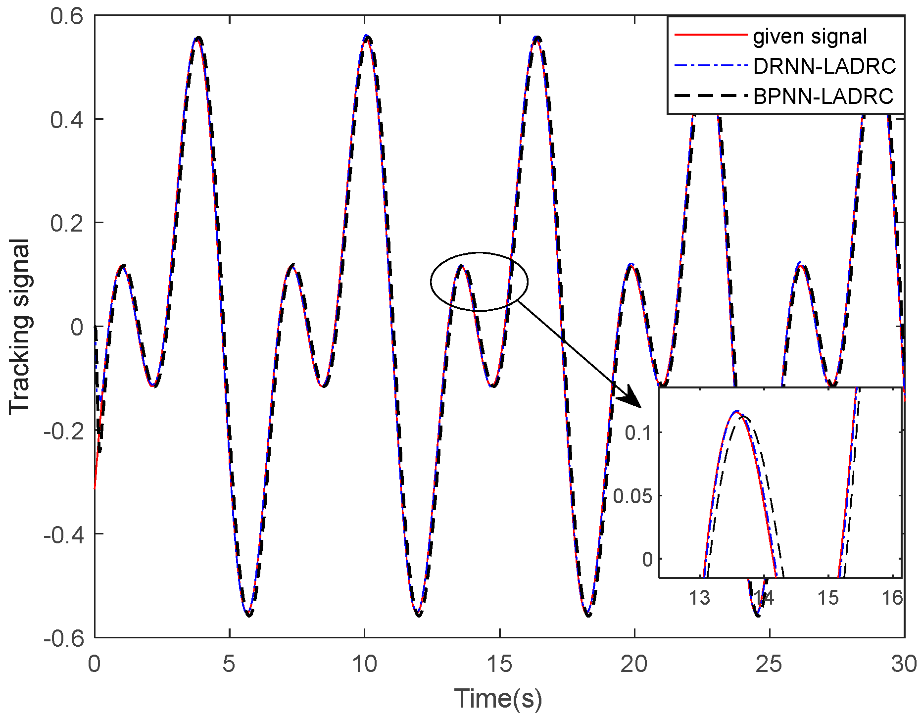
4.3. Case Study 3: Performance Comparison between DRNN-LADRC and BPNN-LADRC

In this part, tracking control of BPNN-LADRC for the radar position servo system is simulated as compared with DRNN-LADRC, which is studied in Case Study 2. The parameters of the BPNN-LADRC are given as: w 0 = 85 ; the number of the neurons in the input layer, hidden layer and output layer, are 4, 5 and 2, respectively. Additionally, the initial value of the weight vectors with respect to the hidden layer and output layer are also random vectors in a certain range. The remaining parameters and input signal are invariant, just as in Case Study 2.
The tracking outputs of the DRNN-LADRC and BPNN-LADRC for the radar system are demonstrated in Figure 16, and the tracking errors are shown in Figure 17. It is clear from Figure 17 that the proposed DRNN-LADRC has better control performance compared with the BPNN-LADRC. It can be seen that the DRNN-LADRC has higher control accuracy and will be more effective in high-precision control. In addition, the tracking error of the BPNN-LADRC fluctuates from −0.043 to 0.026 as shown in Figure 17, which is lower than the tracking error of the LADRC, which fluctuates from −0.048 to 0.044 as shown in Figure 11. The adaptive adjustment curves of k p ( k ) and k d ( k ) in the BPNN-LADRC are shown in Figure 18.

4.4. Case Study 4: Robust Performance Verification

In order to validate the stability of the proposed compound controller DRNN-LADRC and its application value in practical engineering, the robust performance of the proposed compound controller DRNN-LADRC is tested based on the radar system. With the controller parameters unchanged as given in Case Study 2, a constructed function with strong dynamic nonlinearity is added to the radar system, which is expressed as:
f n o n ( t ) = sin ( 2 π t ) 2 ( t , 0 , 1 ) + ( t 1 ) ( t , 1 , 1.5 ) ( t 2 ) ( t , 1.5 , 2.5 ) + ( t 3 ) ( t , 2.5 , 3 )
where ( t , a 1 , a 2 ) = s i g n ( t a 1 ) s i g n ( t a 2 ) 2 , a1 and a2 are positive constants.
At the same time, the Gaussian noise, where the SNR is 40, is added to the servo system, too. The constructed function is shown in Figure 19. As seen, the function is special, which is zero after 3 s. Tracking output and tracking error are shown in Figure 20 and Figure 21, respectively. As seen, the maximum value of tracking error is approximately 0.023, which is acceptable. Therefore, the proposed controller has strong robustness and actual application value.

4.5. Case Study 5: Step Response via the LADRC by Introducing ATD

In this part, tracking control of the radar position servo system via LADRC1, which contains the proposed ATD, is simulated as compared with LADRC2 without the ATD under the same conditions. The input signal turns into a step signal, which steps to 2 at 5 s. The parameters of the LADRC1 are given as: h = 0.001 , K = 300 , L = 120 , σ 1 = 3.5 , σ 2 = 10.25 , w 0 = 180 , k p = 15 , and k d = 10 .
The step responses of LADRC1 and LADRC2 are shown in Figure 22. As shown in Figure 22, ADRC1 has faster tracking performance with an acceptable overshoot of 2.73 % . The control signals of LADRC1 and LADRC2 are shown in Figure 23. As seen, the LADRC1 consumes less energy compared with LADRC2, which smoothly eliminates the excessive control gain in order to track the change of input signal immediately, and the peak value of the control signal has been greatly reduced, which reduces the spike impact on the actuator. Thus, the LADRC1 containing the proposed ATD has more practical application value.

4.6. Discussion

The study of cases 2, 3 and 4 above shows that the designed DRNN-LADRC controller can stably track the given signal and effectively reduce the adverse effects of interference on the radar position servo system. At the same time, compared with the LADRC and BPNN-LADRC, DRNN-LADRC has a more significant signal tracking ability, interference suppression ability and better system adjustment ability. In addition, Case 1 and Case 5 show that the introduction of ATD effectively solves the contradiction between tracking speed and filtering performance, and achieves the purpose of energy saving. It consumes less energy than the TD, successfully eliminates the peak value of the control signal, reduces the peak impact of the control signal on the actuator, and has a more practical application value.

5. Conclusions

In order to improve tracking performances of the radar position servo system facing dead zone and friction nonlinearities, this paper proposes a DRNN-based linear active disturbance rejection control method. Firstly, the ATD, which can adaptively adjust the speed factor and filter factor according to the change rate of the input signal, is designed in order to manage the contradiction between filtering performance and tracking speed; the results of Case Study 1 show that the ATD has good tracking and filtering performances while the input signal is contaminated by Gaussian noise. What is more, the LADRC effectively removes the excessive value of the control signal by introducing the proposed ATD while the LADRC faces step or square wave signal, as demonstrated in Case Study 5, which can track the change of the input signal immediately, reduce the energy of the controller, and reduce the spike impact on the actuator. Secondly, the LADRC has a self-learning ability by introducing the DRNN to optimize its parameters in LSEF in real time, which can adjust the parameters according to the radar system error and reduce the tracking error compared to the traditional LADRC, as demonstrated in Case Study 2. Moreover, the compound controller has higher tracking accuracy of the radar system compared with the BPNN-LADR, as demonstrated in Case Study 3, since the signals within the hidden layer of the DRNN are the feedback signals from the output layer and have different time delays that can predict the plant model accurately. Thirdly, the strong robustness of the proposed compound controller is verified by adding a constructed function with strong dynamic nonlinearity and Gaussian noise to the radar system with the controller parameters unchanged, as demonstrated in Case Study 4.
At present, this paper is limited to theoretical analysis. Due to the limitation of experimental conditions, this paper only simulates the proposed control scheme, so it is necessary to further verify this method through experiments. At the same time, because the radar servo system is composed of the azimuth and elevation axis, this paper only studies the azimuth axis, and will study the algorithm of the whole system in the next step.

Author Contributions

Conceptualization, S.C.; Methodology, G.Z.; Software, G.Z.; Validation, S.C.; Investigation, T.Z.; Resources, S.C.; Data curation, T.Z. All authors have read and agreed to the published version of the manuscript.

Funding

This research received no external funding.

Institutional Review Board Statement

Not applicable.

Informed Consent Statement

Not applicable.

Data Availability Statement

Not applicable.

Conflicts of Interest

The authors declare no conflict of interest.

References

  1. Zhang, Y.; Zhang, Q.P.; Zhang, Y.C.; Pei, J.F.; Huang, Y.L.; Yang, J.Y. Fast Split Bregman Based Deconvolution Algorithm for Airborne Radar Imaging. Remote Sens. 2020, 12, 1747. [Google Scholar] [CrossRef]
  2. Cui, X.-D.; Yao, Z.-G.; Zhao, Z.-L.; Wang, M.-W.; Fan, C.-H.; Su, T. Comparison of Liquid Water Content Retrievals for Airborne Millimeter-Wave Radar with Different Particle Parameter Schemes. J. Trop. Meteorol. 2020, 6, 188–198. [Google Scholar]
  3. Yang, Z.W.; Xu, H.J.; Huang, P.H.; Liu, A.F.; Tian, M. Preliminary Results of Multichannel SAR-GMTI Experiments for Airborne Quad-Pol Radar System. IEEE Trans. Geosci. Remote Sens. 2020, 58, 3822–3840. [Google Scholar] [CrossRef]
  4. Zhou, Q.S.; Li, Z.H.; Shi, J.P.; Mao, Y.X. Robust cognitive transmit waveform and receive filter design for airborne MIMO radar in signal-dependent clutter environment. Digit. Signal Process. 2020, 101, 102709. [Google Scholar] [CrossRef]
  5. Mei, D.; Yu, Z.Q. Active disturbance rejection control strategy for airborne radar stabilization platform based on cascade extended state observer. Assem. Autom. 2020, 40, 613–624. [Google Scholar] [CrossRef]
  6. Ji, H.Y.; Li, Z.J.; Pan, K.D.; Zhang, Z.J. Shipborne Radar Servo Control based on Neural Sliding Mode Variable Structure. In Proceedings of the 2018 IEEE 3rd Advanced Information Technology, Electronic and Automation Control Conference (IAEAC), Chongqing, China, 12–14 October 2018; pp. 231–235. [Google Scholar]
  7. Li, B.A.; Tan, Y.H.; Zhou, L.; Dong, R.L. Robust-nonsmooth Kalman Filtering for Stochastic Sandwich Systems with Dead-zone. Int. J. Control Autom. Syst. 2020, 19, 101–111. [Google Scholar] [CrossRef]
  8. Zhou, Q.; Zhao, S.Y.; Li, H.Y.; Lu, R.Q.; Wu, C.W. Adaptive Neural Network Tracking Control for Robotic Manipulators With Dead Zone. IEEE Trans. Neural Netw. Learn. Syst. 2018, 30, 1–10. [Google Scholar] [CrossRef]
  9. Sun, P. Adaptive Robust Motion Control of an Ironless Permanent Magnet Linear Synchronous Motor with Dead-zone Compensation. In Proceedings of the 2019 22nd International Conference on Electrical Machines and Systems (ICEMS), Harbin, China, 11–14 August 2019; pp. 1–5. [Google Scholar]
  10. Lu, K.X.; Liu, Z.; Lai, G.Y.; Zhang, Y.; Chen, C.L.P. Adaptive Fuzzy Tracking Control of Uncertain Nonlinear Systems Subject to Actuator Dead Zone with Piecewise Time-varying Parameters. IEEE Trans. Fuzzy Syst. 2018, 27, 1493–1505. [Google Scholar] [CrossRef]
  11. Ren, J.B.; Wang, B.F.; Cai, M.J.; Yu, J.P. Adaptive Fast Finite-Time Consensus for Second-Order Uncertain Nonlinear Multi-Agent Systems with Unknown Dead-Zone. IEEE Access 2020, 8, 25557–25569. [Google Scholar] [CrossRef]
  12. Xing, M.M.; Zhou, L.L.; Zhang, C.M.; Xue, K.F.; Zhang, Z.Y. Simulation Analysis of nonlinear friction of rod string in Sucker Rod Pumping System. J. Comput. Nonlinear Dyn. 2019, 14, 091008. [Google Scholar] [CrossRef]
  13. Stribeck, R. Die wesentlichen Eigenschaften der Gleitund Rollenlager–The key qualities of sliding and roller bearings. Z. Des Ver. Dtsch. Ing. 1902, 46, 1342–1348. [Google Scholar]
  14. Wan, L.L.; Zhang, C.; Chen, Y. Adaptive steering control system of the USV with friction compensation. In Proceedings of the 2018 Chinese Automation Congress (CAC), Xi’an, China, 30 November–2 December 2018; pp. 1831–1834. [Google Scholar]
  15. Yang, H.J.; Sun, J.H.; Xia, Y.Q.; Zhao, L. Position Control for Magnetic Rodless Cylinders with Strong Static Friction. IEEE Trans. Ind. Electron. 2018, 65, 5806–5815. [Google Scholar] [CrossRef]
  16. Han, J.Q. From PID to Active Disturbance Rejection Control. IEEE Trans. Ind. Electron. 2009, 56, 900–906. [Google Scholar] [CrossRef]
  17. Gao, Z.Q. Scaling and bandwidth-parameterization based controller tuning. In Proceedings of the 2003 American Control Conference, Denver, CO, USA, 4–6 June 2003; Volume 6, pp. 4989–4996. [Google Scholar]
  18. Gao, Z.Q. On the centrality of disturbance rejection in automatic control. ISA Trans. 2014, 53, 850–857. [Google Scholar] [CrossRef] [Green Version]
  19. Zhang, M.; Zhuang, K.; Zhao, T.; Chen, X.; Xue, J.; Qiao, Z.; Cui, S.; Gao, Y. Bus Voltage Control of Photovoltaic Grid Connected Inverter Based on Adaptive Linear Active Disturbance Rejection. Energies 2022, 15, 5556. [Google Scholar] [CrossRef]
  20. Zhao, F.Z.; Wang, X.; Zhu, T. Low-Frequency Passivity-Based Analysis and Damping of Power-Synchronization Controlled Grid-Forming Inverter. IEEE J. Emerg. Sel. Top. Power Electron. 2022. [Google Scholar] [CrossRef]
  21. Chi, W.C.; Ma, S.J.; Sun, J.Q. A hybrid multi-degree-of-freedom vibration isolation platform for spacecrafts by the linear active disturbance rejection control. Appl. Math. Mech. 2020, 41, 805–818. [Google Scholar] [CrossRef]
  22. Ma, Y.J.; Yang, L.Y.; Zhou, X.S.; Yang, X.; Zhou, Y.L.; Zhang, B. Linear Active Disturbance Rejection Control for DC Bus Voltage Under Low-Voltage Ride-Through at the Grid-Side of Energy Storage System. Energies 2020, 13, 1207. [Google Scholar] [CrossRef] [Green Version]
  23. Liu, Y.Y.; Liu, J.Z.; Zhou, S.L. Linear active disturbance rejection control for pressurized water reactor power based on partial feedback linearization. Ann. Nucl. Energy 2019, 137, 107088. [Google Scholar] [CrossRef]
  24. Li, H.; Liu, X.X.; Lu, J.W. Research on Linear Active Disturbance Rejection Control in DC/DC Boost Converter. Electronics 2019, 8, 1249. [Google Scholar] [CrossRef] [Green Version]
  25. Elkenawy, A.; El-Nagar, A.M.; El-Bardini, M.; El-Rabaie, N.M. Diagonal recurrent neuron network observer-based adaptive control for unknown nonlinear systems. Trans. Inst. Meas. Control 2020, 42, 2833–2856. [Google Scholar] [CrossRef]
  26. Liu, T.; Liang, S.; Xiong, Q.Y.; Wang, K. Adaptive Critic based Optimal Neurocontrol of a Distributed Microwave Heating System using Diagonal Recurrent Network. IEEE Access 2018, 6, 68839–68849. [Google Scholar] [CrossRef]
  27. Kumar, R.; Srivastava, S.; Gupta, J.R.P. Diagonal recurrent neural network based adaptive control of nonlinear dynamical systems using lyapunov stability criterion. ISA Trans. 2017, 67, 407–427. [Google Scholar] [CrossRef] [PubMed]
  28. Kumar, R.; Srivastava, S.; Gupta, J.R.P.; Mohindru, A. Diagonal recurrent neural network based identification of nonlinear dynamical systems with Lyapunov stability based adaptive learning rates. Neurocomputing 2018, 287, 102–117. [Google Scholar] [CrossRef]
  29. Zhang, Q.; Guan, L.W.; Xu, D.X. Odometer Velocity and Acceleration Estimation Based on Tracking Differentiator Filter for 3D-Reduced Inertial Sensor System. Sensors 2019, 19, 4501. [Google Scholar] [CrossRef] [PubMed] [Green Version]
  30. Jiang, R.H.; Liu, C.; Ning, Y.H.; Xie, Y. Improved auto-disturbance rejection controller of radar servo-system with high tracking accuracy. J. Electr. Mach. Control 2019, 23, 102–109. [Google Scholar]
  31. Wang, R.L.; Lu, B.C.; Hou, Y.L.; Gao, Q. Passivity-Based Control for Rocket Launcher Position Servo System Based on ADRC Optimized by IPSO-BP Algorithm. Shock. Vib. 2018, 2018, 5801573. [Google Scholar] [CrossRef] [Green Version]
  32. Zheng, Q.; Goforth, F.J. A disturbance rejection based control approach for hysteretic systems. In Proceedings of the 49th IEEE Conference on Decision and Control (CDC), Atlanta, GA, USA, 15–17 December 2010; pp. 3748–3753. [Google Scholar]
  33. Gao, Z.Q.; Huang, Y.; Han, J.Q. An alternative paradigm for control system design. In Proceedings of the 40th IEEE Conference on Decision and Control, Orlando, FL, USA, 4–7 December 2001; pp. 4578–4585. [Google Scholar]
  34. Dinkar, S.K.; Deep, K. Opposition-based antlion optimizer using Cauchy distribution and its application to data clustering problem. Neural Comput. Appl. 2019, 32, 6967–6995. [Google Scholar] [CrossRef]
  35. Liu, W.C.; Cheng, L.; Hou, Z.G.; Tan, M. An active disturbance rejection controller with hysteresis compensation for piezoelectric actuators. In Proceedings of the 2016 12th World Congress on Intelligent Control and Automation (WCICA), Guilin, China, 12–15 June 2016; pp. 2148–2153. [Google Scholar]
  36. Ku, C.C.; Lee, K.Y. System Identification and Control Using Diagonal Recurrent Neural networks. In Proceedings of the 1992 American Control Conference, Chicago, IL, USA, 24–26 June 1992; pp. 545–549. [Google Scholar]
  37. Liu, T.; Liang, S.; Xiong, Q.Y.; Wang, K. Two-Stage Method for Diagonal Recurrent Neural Network Identification of a High-Power Continuous Microwave Heating System. Neural Process. Lett. 2019, 50, 2161–2182. [Google Scholar] [CrossRef]
  38. Yuan, R.F.; Wu, G.Q. Mechanism analysis of vehicle start-up judder based on gradient characteristic of Stribeck effect. Proc. Inst. Mech. Eng. Part D J. Automob. Eng. 2019, 234, 505–521. [Google Scholar] [CrossRef]
Figure 1. Block diagram of radar position servo system model.
Applsci 12 12839 g001
Figure 2. Structure of the DRNN.
Applsci 12 12839 g002
Figure 3. Block diagram of whole system, where e i represents e 1 or e 2 .
Applsci 12 12839 g003
Figure 4. Structure of the BPNN.
Applsci 12 12839 g004
Figure 5. Tracking outputs of TD while κ = 1.5 , h 0 = 0.002 . (a) Tracking the given signal, (b) Tracking the derivative signal.
Applsci 12 12839 g005
Figure 6. Tracking outputs of TD while κ = 15 , h 0 = 0.002 . (a) Tracking the given signal, (b) Tracking the derivative signal.
Applsci 12 12839 g006
Figure 7. Tracking outputs of TD while κ = 15 , h 0 = 0.2 . (a) Tracking the given signal, (b) Tracking the derivative signal.
Applsci 12 12839 g007
Figure 8. Tracking outputs of the ATD. (a) Tracking the given signal, (b) Tracking the derivative signal.
Applsci 12 12839 g008
Figure 9. The adaptive adjustment curves of the speed factor κ ( k ) and filter factor h 0 ( k ) .
Applsci 12 12839 g009
Figure 10. Tracking outputs of the DRNN-LADRC and traditional LADRC for the radar system.
Applsci 12 12839 g010
Figure 11. Comparison result of tracking errors between the DRNN-LADRC and traditional LADRC.
Applsci 12 12839 g011
Figure 12. Responses of the ATD. (a) Tracking signals of v 1 and v 2 , (b) Adaptive adjustment curves of κ ( k ) and h 0 ( k ) .
Applsci 12 12839 g012
Figure 13. The adaptive adjustment curves of k p ( k ) and k d ( k ) in DRNN-LADRC.
Applsci 12 12839 g013
Figure 14. Sensitivity curve for the radar system with respect to its input.
Applsci 12 12839 g014
Figure 15. Curves of the internal nonlinear disturbances. (a) The friction nonlinearity, (b) The dead zone.
Applsci 12 12839 g015
Figure 16. Tracking outputs of the DRNN-LADRC and BPNN-LADRC for the radar system.
Applsci 12 12839 g016
Figure 17. Comparison result of tracking errors between the DRNN-LADRC and BPNN-LADRC.
Applsci 12 12839 g017
Figure 18. The adaptive adjustment curves of k p ( k ) and k d ( k ) in BPNN-LADRC.
Applsci 12 12839 g018
Figure 19. Curve of the constructed function with strong dynamic nonlinearity.
Applsci 12 12839 g019
Figure 20. Tracking output of the DRNN-LADRC for the new radar servo system.
Applsci 12 12839 g020
Figure 21. Tracking error of the DRNN-LADRC for the new radar servo system.
Applsci 12 12839 g021
Figure 22. Step responses from the LADRC with ATD and LADRC without ATD.
Applsci 12 12839 g022
Figure 23. Comparison results of control signal between the LADRC with ATD and LADRC without ATD.
Applsci 12 12839 g023
Publisher’s Note: MDPI stays neutral with regard to jurisdictional claims in published maps and institutional affiliations.

