Article

Combustion and Explosion Characteristics of Pulverised Wood, Valorized with Mild Pyrolysis in Pilot Scale Installation, Using the Modified ISO 1 m3 Dust Explosion Vessel

by
Muhammad Azam Saeed
1,2,*,
Lukasz Niedzwiecki
3,4,*,
Muhammad Yousaf Arshad
2,
Jan Skrinsky
4,
Gordon E. Andrews
1 and
Herodotos N. Phylaktou
1
1
School of Chemical and Process Engineering, University of Leeds, Leeds LS2 9JT, UK
2
Department of Chemical Engineering, University of Engineering and Technology, GT Road, Lahore 39161, Pakistan
3
Department of Energy Conversion Engineering, Wrocław University of Science and Technology, Wyb.Wyspiańskiego 27, 50-370 Wrocław, Poland
4
Energy Research Centre, Centre for Energy and Environmental Technologies, VŠB—Technical University of Ostrava, 17. Listopadu 2172/15, 708 00 Ostrava, Czech Republic
*
Authors to whom correspondence should be addressed.
Appl. Sci. 2022, 12(24), 12928; https://doi.org/10.3390/app122412928
Submission received: 8 November 2022 / Revised: 7 December 2022 / Accepted: 12 December 2022 / Published: 16 December 2022
(This article belongs to the Special Issue The Pyrolysis of Biomass: Reaction Mechanism and Product Application)

Abstract

:

Featured Application

Design of explosion safety measures for torrefaction installations and design of pulverized-fired burners for biocoal.

Abstract

Biomass is a renewable energy source with great potential worldwide and in the European Union. However, valorization is necessary to turn many types of waste biomass into a tradable commodity that has the potential to replace coal in power plants without significant modifications to firing systems. Mild pyrolysis, also known as torrefaction, is a thermal valorization process of low-quality biomass that could be suitable for such a purpose. In this work, typical Spruce-Pine-Fir residues from a sawmill were tested in terms of the explosion and flame propagation properties. The ISO 1 m3 dust explosion vessel was used, with a modified and calibrated dust dispersion system that could cope with very coarse particles. The deflagration index, Kst, was higher for the torrefied sample, with a peak at 36 bar m/s compared with 27 for the raw biomass. The peak flame speeds were similar for both samples, reaching 1 m/s. The peak Pmax/Pi was between 7.3 and 7.4 bar for both untreated and torrefied biomass. The mechanism for coarse particle combustion is considered to be influenced by the explosion-induced wind blowing the finer fractions ahead of the flame, which burns first, subsequently devolatilizing the coarser fractions.

1. Introduction

Extensive effort is needed to achieve the ambitious climate goals set by the Paris agreement. Biomass is a considerable renewable energy source, which fulfilled approx. 19% of heating needs and almost 3% of electricity needs in 2019, in the EU [1]. However, biomass processing generates particles, the accumulation of which could be considered an important hazard at various stages of bio-based supply chains [2,3,4]. Due to the possible loss of life and high cost due to such explosions, a cautious approach is adopted, and significant emphasis is put on prevention aspects, focusing on the elimination of potential explosion hazards both in biomass processing and utilization facilities [5,6].
With increasing interest in novel processes for the valorization of biomass [7,8], the necessity of investigations focused on process safety, as well as on the characteristics of the valorized biomass with respect to its subsequent utilization, is evident. Torrefaction, also known as mild pyrolysis [9,10], is one of the processes that offer important benefits in using valorized biomass as a sustainable solid fuel [11,12]. It offers important advantages across the whole bioenergy value, improving solid fuel properties [13,14,15] and offering advantages for various energy conversion processes, such as combustion [16,17,18] or gasification [19,20,21]. The influence is multifaceted. Firstly, torrefaction has an enhancing influence on the reactivity of biomass, which has been confirmed by many studies [22,23,24,25]. Secondly, torrefaction improves grindability and makes biomass more brittle [26,27,28]. This is important since particle size distribution has an immense influence on the behavior of solid fuels during combustion [29,30,31]. Moreover, torrefaction is capable of removing some part of chlorine from biomass [32], followed by the formation of chloromethane [33]. This has a positive influence in terms of the formation of deposits in boilers [34], and the diminishing influence of torrefaction on the formation of deposits has been confirmed empirically for the combustion of torrefied Palm Kernel Shells in small-scale boilers [35].
A number of published works confirmed the feasibility of using torrefied biomass to decrease the carbon footprint of thermal power plants by co-firing torrefied biomass with coal at ratios much higher in comparison to untreated biomass [36,37]. However, not much is known about the process safety of torrefied biomass, thus creating potential business uncertainties for large-scale users, such as power plants, where explosions are related to significant human and financial losses. Huescar-Medina et al. [38] investigated the influence of torrefaction on selected parameters of dust explosivity of wheat and willow, reporting a slight increase in (dp/dt)max and KSTmax due to torrefaction. Huescar-Medina et al. [39] also characterized the explosion reactivity of torrefied spruce. Abelha, Carbo, and Cieplik [40] reported the explosivity properties of dusts from torrefied biomass pellets and measured flame front velocity using an in-house developed method. Flame speeds have been compared for coal and biomass by various sources [41,42,43].
Due to the reported increase in the biomass explosion parameters caused by torrefaction, it seems sensible to determine if coarse particles, typically not considered hazardous in the case of raw biomass, should be treated as a potential risk for torrefied materials. Moreover, a good understanding of combustion behaviour and knowledge of laminar burning velocity is critical in terms of the design of burners, as well as assessment of consequences of fuel change for existing burners, whether that be a transition from coal to torrefied biomass (also known as biocoal) or transition from untreated biomass to biocoal. Therefore, the aim of this paper is to perform a comparative analysis, investigating both explosion properties as well as laminar burning velocities for both torrefied and untreated biomass—i.e., SPF (Spruce-Pine-Fir) residue from a typical, small-scale sawmill.

2. Materials and Methods

2.1. Mild Pyrolysis Process

Bulk samples of the woody mixture and its torrefied sample comprising spruce, pine, and fir were received from RFT, Liverpool. A sample of valorized material was produced using patented torrefaction technology, as shown in Figure 1, developed by the company. The technology is based on the indirect delivery of the process heat through phase change of the heat transfer medium (Thermal fluid). The pilot unit can process approximately 20 kg/h of biomass. Processing capacity is determined mostly by the moisture content of a feedstock and requirements for the parameters of the obtained torrefied product. The torrefaction process used in this work heats biomass by direct contact with hot, hollow, flat surfaces (trays). The temperature was measured by K-type thermocouples for each tray individually, with the tip of the thermocouple being in proximity to the bottom side of the top plate. 3 K-type thermocouples measure temperature in proximity to the bottom side of the bottom plate for Trays 1, 3, and 4. Due to rotating elements (paddles), it was not possible to measure the temperature inside the bed or on the top side of the (top) plate.
Material delivered for the test performed for this work (test in the 1 m3 vessel) was a subject of mild pyrolysis. The average temperature for all the trays of the reactor, measured in proximity to the bottom side of the top plate, was 302.9 °C. An important novelty of this particular reactor, in comparison to other modern torrefaction reactors [44,45,46], is the ability to achieve very low residence times due to enhanced mixing of the bed. The mean residence time of biomass particles inside the reactor was 7 min. Typically, the residence time for mild pyrolysis of biomass ranges between 30 and 90 min [47,48,49]. However, shorter residence times of 5–12 min have been proposed [50,51]. Shorter residence times could be considered beneficial, as the productivity of a reactor of a certain size depends on its residence time in a linear manner. However, heat exchange limitations within the bed should always be carefully considered, with mixing being especially important.

2.2. Characterization of Feedstock and Product

Torrefied coarse wood particles (less than 3 mm) were the fuel used in this work. Biomass came from wood processing, originating from three different kinds of wood: Spruce (S), Pine (P), and Fir (F). These three wood species were mixed in roughly equal proportions during wood processing, and it was not possible to separate each species. The untreated sample is a typical example of residues from wood processing in the UK. Two samples were investigated: the raw coarse ground biomass, marked as Spruce-Pine-Fir Raw (SPFR), and the torrefied biomass, marked as Spruce-Pine-Fir torrefied (SPFT), across the manuscript. Their properties are summarized in Table 1 for their elemental composition and their volatile, fixed carbon, and ash content.
The elemental analysis, performed using Perkin Elmer 2400 analyzer, was used to determine the stoichiometric air-to-fuel ratio, A/F [52,53,54]. TGA analysis was used to determine the volatile, fixed carbon, ash, and moisture content of the biomass [55,56,57]. The Shimadzu TGA-50 was used, with alumina crucibles, with sample size of approx. 10 mg. Volatile matter content and ash content were determined in separate runs. The program for determination of volatile matter content consisted of heating the biomass up to 105°C with the heating rate of 10 °C/min, followed by a hold period of 30 min. Subsequently, the sample was heated up to 900 °C with the heating rate of 10 °C/min, in N2 atmosphere, followed by a holding time of 2 h. For determination of ash content, the same step was used for drying. Subsequently, the sample was heated up to 550 °C with the heating rate of 10 °C/min, in the air atmosphere, followed by a holding time of 2 h. Such temperature ensured that no inorganics could be removed from the biomass [34]. Higher heating value was determined using IKA C2000 bomb calorimeter.
Table 1 shows that torrefaction produced an increase of elemental carbon with a reduction in the % oxygen. This produced a 10% increase in the stoichiometric A/F. The calorific value on a dry basis was increased by 9%, as shown in Table 1.

2.3. Particle Size Distribution

The raw and torrefied biomass samples were of the coarse particle size distribution of less than 3 mm that were sieved to less than 1 mm for the present work. The sample particle size was analyzed by a Malvern Mastersizer. The particle size distributions for the raw and torrefied samples are summarised in Table 2. This shows that torrefaction resulted in the reduction of the particle size by 20% on a d10 basis and 18% on an SMD (Surface mean diameter) or equal surface area basis. This could be attributed to mechanical attrition in the reactor and, to some extent, to the shrinking effect during drying (the first stage of the torrefaction process). However, the proportion of fines (d < 100 µm) was reduced slightly by the torrefaction process. This was probably caused by the entrainment of the fine particles, with torgas to the thermal oxidizer.

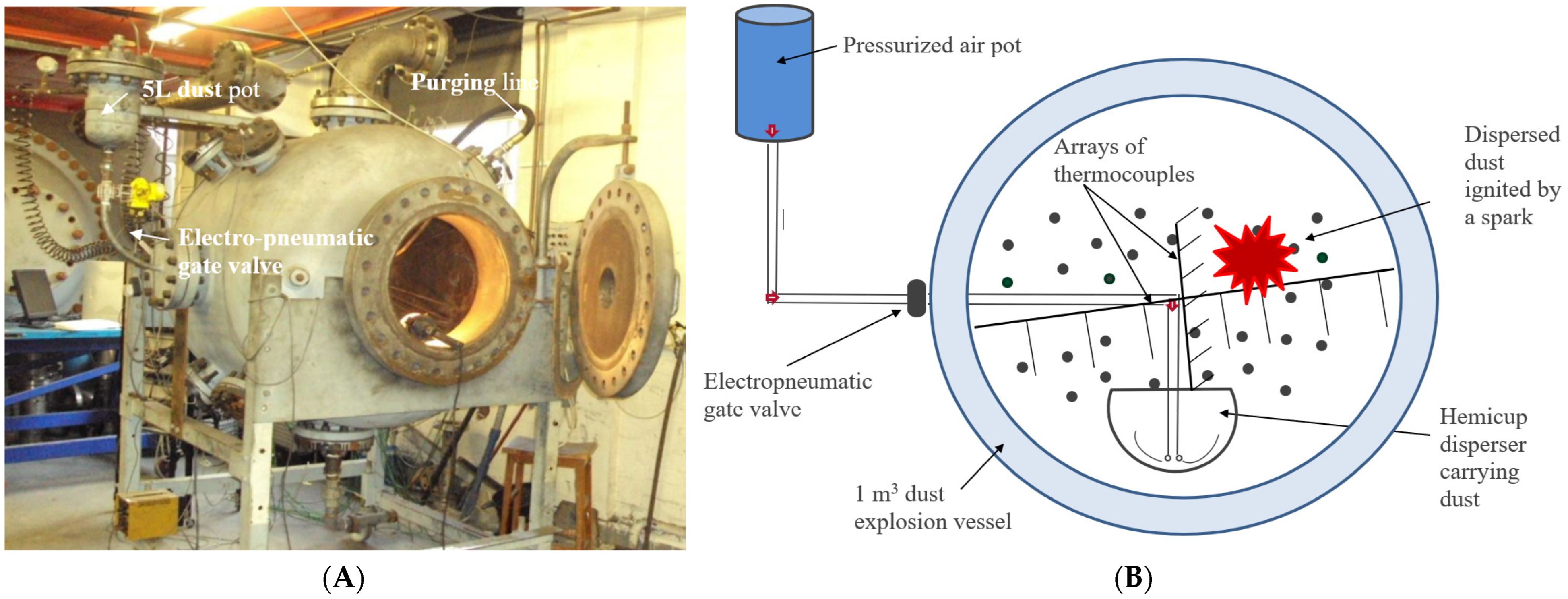
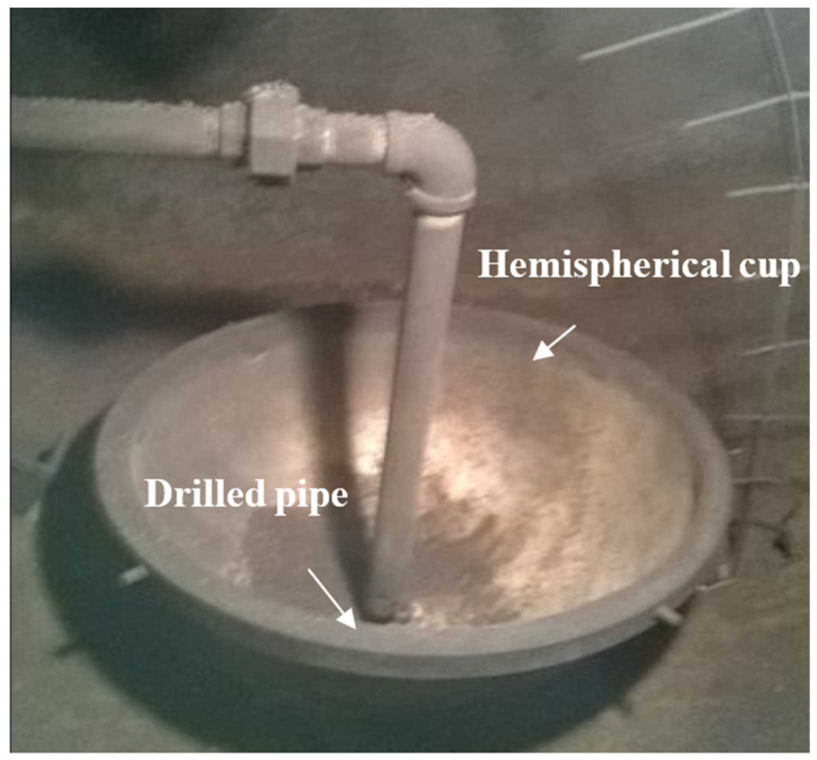
2.4. The Modified ISO 1 m3 Dust Explosion Vessel for Coarse Biomass Powders

The modified ISO 1 m3 vessel, shown in Figure 2, was used for the determination of the flammability and explosion characteristics of biomass samples. The standard C-ring particle injector was found to be incapable of dispersing the pulverized coarse woody biomass, as the particles were compressed and blocked the flow in the delivery C ring. This occurred even when the woody biomass was sieved to less than 63 µm. SEM analysis of the particles sieved to <63 µm shows that cylinders of diameter less than 63 µm occur with lengths much greater than 63 µm, and these block in the C-ring [41]. Several modifications were investigated, but for particles used in the power station burner and pellet store clouds of dust, no externally located dust injection system could be made to work. Thus, the principle of placing dust in an external pot and injecting it with 20-bar compressed air, developed by Bartknecht [58], had to be abandoned.
The Hartmann method [52] of dust dispersion was developed for the 1 m3 explosion vessel, whereby the dust was placed inside the vessel in a chamber and dispersed with a blast of air. A hemispherical container was placed on the floor of the 1 m3 vessel, as shown in Figure 3. This was 0.4 m in diameter with a volume of 17 L and could contain 3.5 kg of biomass particles with a bulk density of 200 kg/m3. This was dispersed with compressed air from a 10 L external volume at 20 bar pressure. The air was fed via a pipe the same size as the “C” ring to the bottom of the hemisphere and injected through a series of holes around and along the tube end, with the same total hole area as for the C-ring injector. Calibration of the drilled pipe hemispherical cup injection system showed that an ignition delay of 0.5 s was required to give the same Kst for corn flour as the standard ISO 1 m3 design.
The 1 m3 vessel was modified for the testing of a wide range of particle size distribution of biomass. Different dispersers were designed and calibrated for testing the fibrous biomass samples that were not passing through standard C-ring disperser and were choking the holes with a significant amount left over in the pot. Out of different designs of the dispersers, the drilled pipe hemispherical disperser was calibrated using standard fine corn flour and Colombian coal samples based on the same explosibility results by varying the ignition delay as compared to a standard C-ring disperser. In the drilled pipe hemispherical disperser, the weighed dust was placed in the hemispherical cup inside, at the bottom centre part of the vessel. Compressed air lifted the dust particles by transverse motion and dispersed the sample in the vessel. The dispersed dust was ignited after calibrated optimum ignition delays of these dispersers. Post-explosion residues were corrected for the unburnt dust and the ash contents for the actual burnt concentrations.

2.5. The Measurement of Spherical Flame Speed and Burning Velocity

Sets of thermocouples were placed horizontally and vertically in the vessel to detect the rate of flame arrival. Twelve thermocouples were placed in the horizontal direction on both sides of the ignition source to measure the flame propagation right and left to the igniter. Another eight thermocouples were installed vertically downward. So, the three sets of thermocouples recorded the time of flame arrival and helped to measure the average flame speeds in three directions. The sets of thermocouples recorded the time of flame arrival that was used to plot the time of arrival of the flame as a function of the position of the thermocouple, and the slope of the linear line determined the average flame speeds. It was found that the average flame speed was the same, with a minor deviation of 2%, showing the uniform propagation of flame. Moreover, these average flame speeds were measured in the constant pressure region in between 0.2 to 0.7 of the vessel radius as in the initial 20%, there was igniter affecting the flame, and after 70% of the vessel radius, pressure rise starts to change significantly. Windmill Wavecap software (12.70) was used for capturing the data, and IMC FAMOS (Fast acting and monitoring of signals) was used for the analysis of the experimental results. The rate of pressure rise was determined from the pressure rise signal after some degree of smoothing. Pressure transducers had factory-calibrated accuracy of 99% in pressure measurements. The errors in thermocouples due to response time were ignored as the relative distances were considered for flame speed measurements. The flame speed should be converted to a burning velocity by dividing it by the adiabatic expansion ratio at constant pressure. However, the calculation of adiabatic flame temperatures of biomass is difficult due to the compositional differences and the ash and water content. Instead, the procedure of Cashdollar [59] was used that takes the measured maximum to initial pressure as the expansion ratio.

2.6. The Explosion Residue and Implications for the Flame Front Equivalence Ratio, Ø

After each test, significant unburnt material was found inside the 1m3 vessel and in the hemispherical cup. This residue was collected, its mass was measured, and its composition was analyzed and compared to the pre-test material in Table 1. The size distribution of the residue was also determined, and these are given in Table 2.
In this work, we report the explosion mixture concentration in terms of the Equivalence Ratio [59]:
E q u i v a l e n c e   r a t i o ,   Ø = S t o i c h i o m e t r i c   A i r   t o   F u e l   b y   m a s s A c t u a l   A i r   t o   F u e l   b y   m a s s ,
For the very coarse-size mixtures used in the present work, it is proposed that fine particles play an important role in flame propagation. The propagation of a flame in dust clouds consisting of very coarse particles was postulated as being due to the initial flame front burning only the fine particles. Due to the burnt gas expansion, the explosion-induced wind ahead of the flame front would separate the fine and coarse particles due to particle drag. The particle drag was greater for large particles, and these would lag behind the flame, which would burn in the fine fraction. For the flame to propagate in the fines their concentration has to be flammable, and hence there is a need to express the equivalence ratio of the fines (<100 µm) separate from the overall equivalence ratio. The equivalence ratio based on fine particles smaller than 100 µm is given by (2).
F i n e s   ( 100   μ m )   E q u i v a l e n c e   r a t i o = S t o i c h i o m e t r i c   A i r   t o   F u e l   b y   m a s s A c t u a l   A i r   t o   F u e l   b y   m a s s < 100   μ m   ,
The stoichiometric air to fuel ratio was determined using Equation (3):
S t o i c h i o m e t r i c   A i r   t o   F u e l   b y   m a s s = 1 0.232   · ( 8 3 · c + 8 · h o ) ,   kg air / kg fuel
where c, h, and o indicate mass fractions of carbon, hydrogen and oxygen.
The nominal equivalence ratio (1) is the actual air to fuel by mass, as the total mass of injected and initial air in the 1 m3 divided by the mass of biomass placed in the hemisphere (including fine and coarse size particles). The fines equivalence ratio (2) is based on the same air mass but divided by the mass of particles <100 µm.
Both of these definitions assume that all coarse and fine dusts burn in the explosion. However, some of the fine and coarse particles were found in the post-explosion residues, as was found in previous biomass dust explosion work for particle size <63 µm. This was because the explosion-induced wind would result in the particles ahead of the flame hitting the wall and then not burning. Thus, a mixture concentration based on the dust mass placed in the hemisphere is not the concentration that the flame propagated through [58,59]. There are two possible definitions for the two equivalence ratio equations in (1) and (2). The first uses the nominal mass of the biomass and associated fines placed in the hemisphere, referred to as the nominal equivalence ratio. The second definition uses the difference in the nominal mass of dust and the residual mass of dust to give the actual mass of dust that was burned in the explosion. This is the flame front equivalence ratio or corrected equivalence ratio.

3. Results and Discussion

3.1. Fraction of Original Mass That Burns in the Explosion

Table 1 shows that the explosion residues have almost the same composition as that of their parent sample, apart from the higher ash content of the deposits due to the accumulation of burnt biomass ash. Table 2 shows that their size distributions were very similar for the torrefied biomass but were smaller for the raw biomass. This could be due to a reduction in size during the flame propagation and wall impact of the unburned biomass. However, it would be expected that similar effects would occur with the torrefied biomass. The data in Table 1 and Table 2 indicate that the unburned biomass residues are the original injected material, not partially burnt products. There was no evidence that only the fines burned, leaving all the coarse biomass unburned. Thus, an equivalence ratio for the explosion based on all the dust injected taking part in the explosion, referred to as the nominal equivalence ratio, is not the equivalence ratio at the flame front. The mass of biomass that burnt in the explosion (nominal mass—residual mass) is the basis of the flame front equivalence ratio, which will be referred to as a corrected equivalence ratio. As the quantity of biomass fuel burned in each explosion is less than the nominal amount, the flame front equivalence ratio must be leaner than the nominal.
The origin of this unburnt biomass was postulated by Sattar et al. [58] for biomass and other dusts, to be caused by the action of the explosion-induced wind ahead of the flame front in blowing particles away from the flame and eventually onto the vessel wall, where they fell onto the floor of the vessel at the end of the explosion. While in contact with the wall, they acted as an insulating layer that reduced the rate of vessel cooling, as shown by the reduction in the rate of pressure loss. As the finer particles will move with the wind and the coarser will lag, this is the origin of the explanation in the present work of the coarse particles burning in the products of an initial fine particle flame.

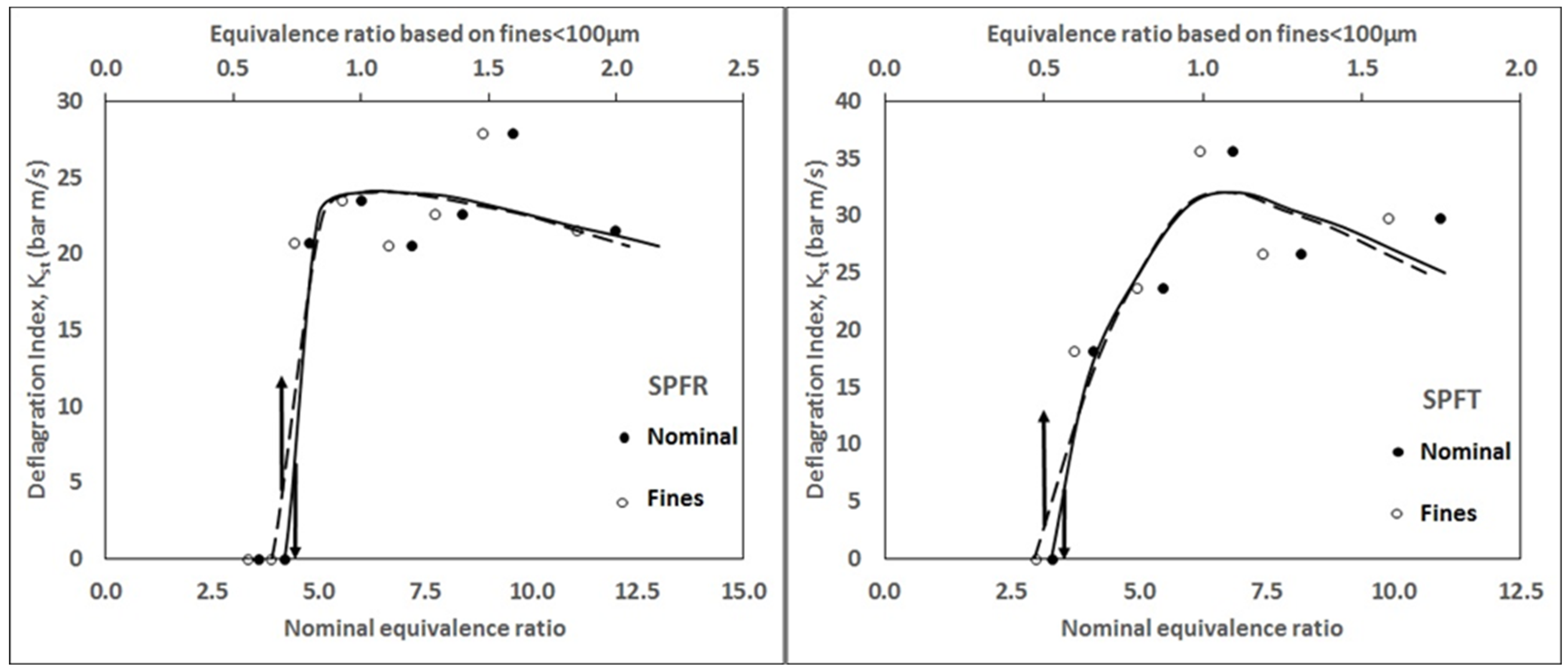
3.2. Deflagration Index

The Deflagration Index, Kst, as a function of the Equivalence Ratio, Ø, is shown in Figure 4. The peak Kst was measured to be 27 and 36 bar∙m/s for raw and torrefied wood mixture, respectively. The peak Kst for the torrefied wood mixture occurred at a nominal Ø of 6.8 (Fines Ø ~ 1). For the raw wood mixture, the maximum Kst occurred at Ø = 9.6 (Fines Ø ~ 1.6). Figure 5 shows that the torrefied sample had higher Kst at all Ø and was much more reactive (1/3rd more) at the most reactive concentration. For Ø > 6, based on the nominal concentration, there were some fluctuations in Kst due to the excess mass of fuel affecting the flame propagation. For higher fuel concentration, the additional mass of fuel absorbs the heat from the burnt gases, and this reduces Kst slowly as fuel mass is increased. Biomass with coarse particle size, whether raw or torrefied, showed their most reactive concentration at overall Ø, giving the Ø for the fines near stoichiometric. This indicates that the flame propagated in the fines.
A mechanism for coarse biomass powders to burn in a propagating flame is proposed to explain these results, which is an extension of that used to explain why about half of the initial dust does not burn in the explosion [59,60]. The action of the wind, induced by the expanding spherical flame, on particles ahead of the flame with a variable size distribution is to blow the smallest particles close to the gas velocity, with the larger particles lagging due to drag effects. The flame front is then driven by the finer particles, and the larger particles lag and are heated to ignition by the hot burnt gases from the flame front. The mixture has to be very rich (nominal concentration) for the finer particles ahead of the flame to burn close to Ø = 1, as <20% of the total mass of particles was in the size fraction that will burn easily, as shown in Table 2. A flammable mixture of 20% fine particles with ØMEC of 0.2 needs Øfines of at least 1.0 for the overall mixture to burn. This is close to the results in Figure 5 for SPF raw and torrefied samples. With this mechanism, the larger particles are gasified in the rich mixture of the hot burnt gases from the flame burning in the finer fraction. This releases CO and H2, which have insufficient oxygen to burn, but the volume release keeps the explosion pressure high for rich mixtures.
The maximum explosion pressure, Pmax, to the initial pressure, Pi, is shown in Figure 5 as a function of the nominal equivalence ratio, Ø. This shows that the normalized peak explosion pressure rise was 7.4 bar for SPFT and 7.3 bar for SPFR, which shows that the two materials burnt with a similar flame temperature. These are large pressure rises indicating that a high proportion of the coarse mixture had burnt as well as the fines burning. In spite of the low reactivity of these mixtures, as shown by their low Kst, the overpressure was high and would destroy any process plant enclosure used in processing this material. These pressure rises were lower than those of purely fine particles of biomass, whereas, for similar biomass composition, Pmax/Pi was about 8.5 bar [58,59].

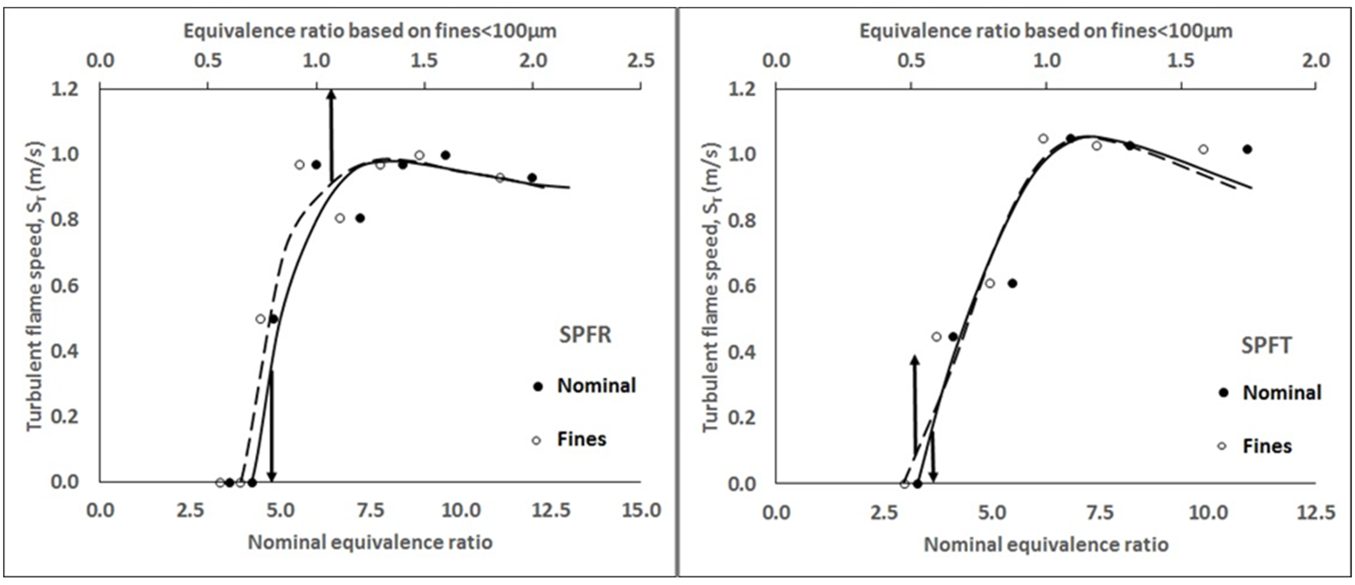
3.3. Flame Speed and Burning Velocity Measurements

The measured turbulent spherical flame speeds, ST, for SPFR and SPFT are shown in Figure 6 as a function of the equivalence ratio, Ø. These measurements of the mixture reactivity are very similar in their dependency on the equivalence ratio, Ø, as for the Kst results in Figure 4. However, the two peak ST for the raw and torrefied biomass were very similar at close to 1.0 m/s compared with a significant difference in Kst in Figure 4. This difference may be due to the turbulent flame speed, ST being measured in the constant pressure period of the explosion and Kst is measured just before the peak pressure. Figure 6 also shows that for rich mixtures, the flame speed remains high as the fuel concentration increases. This is considered to be explained by the mechanism of the coarse biomass flame front with the flame driven by the finer particles in the mixture and the coarse particles gasified behind the flame front. As more fuel is added, the Ø of the fine fraction flame increases and the temperature of this initial combustion increases, which results in more efficient devolatilization of the coarse fraction and the gas volume released in the gasification reactions increases which cause the pressure to remain high even though for gases the pressure would fall for richer mixtures.
Figure 7 compares as a function of the mass mean particle size, d50, the present peak ST with previous measurements [30,39,42,58,59] of ST for fine pulverized raw biomass and thermally treated biomass. The previous data was all for biomass sieved to <63 µm for raw and torrefied biomass (different torrefaction processes) and then analyzed for the size distribution. The d50 as high as 200 µm was found compared with 350–450 µm in the present work where the particles were sieved to <1 mm. Figure 8 presents the same data in terms of the Kst. Figure 7 and Figure 9 show that the present results for coarse-based biomass are consistent with previous results with a prime dependence of the mixture reactivity on the particle size. When compared at the same d50, the difference in mixture reactivity between the raw and torrefied biomass was small, with the torrefied biomass having a slightly greater dependence on size, mainly as a result of the present results.
The laminar burning velocity, UL, of a dust/air mixture was determined from the measured ST in Figure 9 by dividing by the calibrated turbulence factor for the ISO 1 m3 using the calibrated turbulence factor and then using Equation (1). The results are shown in Figure 9 and show very low values of UL for the coarse particles in the present work.
A very good linear correlation was found between the peak turbulent flame speeds and peak deflagration index of the raw and thermally treated wood samples, as shown in Figure 10. It showed a reduction in the explosibility characteristics with increasing particle size. A similar linear correlation was also observed for the raw and thermally treated wood samples’ peak laminar burning velocity and peak deflagration index.

3.4. Minimum Explosible Concentration, MEC

The MEC of the coarse SPF raw and torrefied biomasses were determined from Figure 5, Figure 6 and Figure 7 to be 4.2Ø and 3.3Ø, respectively based on nominal concentration. Based on fuel concentration for mass smaller than 100 µm, these are roughly 1/6th of their nominal concentration. Lean flammability limits based on fines (<100 µm) equivalence ratio (assuming 100% consumption of fines) were 0.65Øfines and 0.5Øfines for raw and torrefied SPF wood mixtures, respectively. These concentration of flammability limits are for 0% ignition probability to avoid the risk of marginalized ignited concentrations. Moreover, there are no specific criteria defined for the resolution of lean flammability limits as for gas lean flammability limits. According to European dust explosion standards, a 50% reduction of dust concentration for the testing of dust explosibility characteristics was employed, which is a poor resolution for MEC. So, it is better to use the concentration of 0% ignition probability for the MEC of dusts. The MEC based on the fines’ equivalence ratio is realistic and higher than the 100% fine size dusts mixture due to less proportion of fines with the inerting effect of coarse size particles affecting the efficient propagation of flame.

4. Conclusions

Raw and commercially torrefied SPF biomass samples were investigated for very coarse fractions, <1 mm, using an ISO 1 m3 explosion vessel modified and calibrated to enable coarse woody biomass samples to be dispersed. The size distributions of the sieved samples show that the torrefaction process produced finer fractions than in the raw biomass, and this led to the torrefied samples having a leaner MEC and higher reactivity in leaner mixtures than for raw samples. Both unprocessed and torrefied SPF exhibited explosions, but only for rich mixtures. The peak Pmax/Pi was between 7.3 and 7.4 bar for both unprocessed and torrefied SPF. The deflagration index, Kst, was higher for the torrefied sample, with a peak at 36 bar m/s compared with 27 for the raw biomass. The peak flame speeds were similar for both samples, reaching 1 m/s. Post-explosion residues showed almost the same composition and size distribution as their parent samples, indicating that they were the parent material. The equivalence ratio at the flame front was taken as the initial mass of dust minus the residue, Ø. A mechanism was proposed for coarse biomass flame propagation whereby the flame propagated in the fine fraction, and the coarse particles were devolatilized in the burnt gases behind the fine particle flame front. This explained the MEC results and the most reactive mixture being very rich.

Author Contributions

Conceptualization, G.E.A. and H.N.P.; methodology, G.E.A. and H.N.P.; validation, M.A.S.; formal analysis, M.A.S.; investigation, M.A.S. and L.N.; resources, G.E.A. and H.N.P.; data curation, M.A.S., M.Y.A. and J.S.; writing—original draft preparation, M.A.S. and L.N.; writing—review and editing, M.A.S., L.N., M.Y.A., J.S.; visualization, M.A.S., M.Y.A. and J.S.; supervision, G.E.A. and H.N.P.; project administration, G.E.A. and H.N.P.; funding acquisition, G.E and H.N.P. All authors have read and agreed to the published version of the manuscript.

Funding

The authors acknowledge the financial support provided by University of Engineering and Technology Lahore, Pakistan for carrying out this research work. Financial support of this work from the National Science Centre, Poland—project no. 2019/33/N/ST8/02641, is gratefully acknowledged.

Institutional Review Board Statement

Not applicable.

Informed Consent Statement

Not applicable.

Data Availability Statement

Not applicable.

Acknowledgments

The authors are grateful to Renewable Fuel Technologies UK Ltd. for providing the raw and torrefied wood mixture samples for pursuing this work.

Conflicts of Interest

The authors declare no conflict of interest.

References

  1. Tzelepi, V.; Zeneli, M.; Kourkoumpas, D.S.; Karampinis, E.; Gypakis, A.; Nikolopoulos, N.; Grammelis, P. Biomass Availability in Europe as an Alternative Fuel for Full Conversion of Lignite Power Plants: A Critical Review. Energies 2020, 13, 3390. [Google Scholar] [CrossRef]
  2. Mračková, E.; Schmidtová, J.; Marková, I.; Jad’ud’ová, J.; Tureková, I.; Hitka, M. Fire Parameters of Spruce (Picea Abies Karst. (L.)) Dust Layer from Different Wood Technologies Slovak Case Study. Appl. Sci. 2022, 12, 548. [Google Scholar] [CrossRef]
  3. Portarapillo, M.; Danzi, E.; Sanchirico, R.; Marmo, L.; Di Benedetto, A. Energy Recovery from Vinery Waste: Dust Explosion Issues. Appl. Sci. 2021, 11, 11188. [Google Scholar] [CrossRef]
  4. Tureková, I.; Marková, I. Ignition of Deposited Wood Dust Layer by Selected Sources. Appl. Sci. 2020, 10, 5779. [Google Scholar] [CrossRef]
  5. Eckhoff, R.K.; Li, G. Industrial Dust Explosions. A Brief Review. Appl. Sci. 2021, 11, 1669. [Google Scholar] [CrossRef]
  6. Garrido-Ceca, I.; Puig-Gamero, M.; Ramírez-Gómez, Á. Influence of Bends in the Functionality of Passive Explosion Isolation Valves. Appl. Sci. 2022, 12, 11654. [Google Scholar] [CrossRef]
  7. Knapczyk, A.; Francik, S.; Jewiarz, M.; Zawiślak, A.; Francik, R. Thermal Treatment of Biomass: A Bibliometric Analysis—The Torrefaction Case. Energies 2020, 14, 162. [Google Scholar] [CrossRef]
  8. Kantorek, M.; Jesionek, K.; Polesek-Karczewska, S.; Ziółkowski, P.; Stajnke, M.; Badur, J. Thermal Utilization of Meat-and-Bone Meal Using the Rotary Kiln Pyrolyzer and the Fluidized Bed Boiler—The Performance of Pilot-Scale Installation. Renew. Energy 2021, 164, 1447–1456. [Google Scholar] [CrossRef]
  9. Krochmalny, K.; Niedzwiecki, L.; Pelińska-Olko, E.; Wnukowski, M.; Czajka, K.; Tkaczuk-Serafin, M.; Pawlak-Kruczek, H. Determination of the Marker for Automation of Torrefaction and Slow Pyrolysis Processes—A Case Study of Spherical Wood Particles. Renew. Energy 2020, 161, 350–360. [Google Scholar] [CrossRef]
  10. Kerdsuwan, S.; Laohalidanond, K.; Gupta Ashwani, K. Upgrading Refuse-Derived Fuel Properties From Reclaimed Landfill Using Torrefaction. J. Energy Resour. Technol. 2021, 143, 021302. [Google Scholar] [CrossRef]
  11. Rasheed, T.; Anwar, M.T.; Ahmad, N.; Sher, F.; Khan, S.U.-D.; Ahmad, A.; Khan, R.; Wazeer, I. Valorisation and emerging perspective of biomass based waste-to-energy technologies and their socio-environmental impact: A review. J. Environ. Manag. 2021, 287, 112257. [Google Scholar] [CrossRef]
  12. Nunes, L.J.R.; Loureiro, L.M.E.F.; Sá, L.C.R.; Silva, H.F.C. Sugarcane Industry Waste Recovery: A Case Study Using Thermochemical Conversion Technologies to Increase Sustainability. Appl. Sci. 2020, 10, 6481. [Google Scholar] [CrossRef]
  13. Szwaja, S.; Magdziarz, A.; Zajemska, M.; Poskart, A. A Torrefaction of Sida Hermaphrodita to Improve Fuel Properties. Advanced Analysis of Torrefied Products. Renew. Energy 2019, 141, 894–902. [Google Scholar] [CrossRef]
  14. Sh, L.; Lee, B.H.; Lee, Y.J.; Jeon, C.H. Comparing the Physicochemical Properties of Upgraded Biomass Fuel by Torrefaction and the Ashless Technique. Appl. Sci. 2019, 9, 5519. [Google Scholar] [CrossRef] [Green Version]
  15. Luo, H.; Lu, Z.; Jensen, P.A.; Glarborg, P.; Lin, W.; Dam-Johansen, K.; Wu, H. Experimental and Modelling Study on the Influence of Wood Type, Density, Water Content, and Temperature on Wood Devolatilization. Fuel 2020, 260, 116410. [Google Scholar] [CrossRef]
  16. Lu, Z.; Jian, J.; Jensen, P.A.; Wu, H.; Glarborg, P. Influence of Torrefaction on Single Particle Combustion of Wood. Energy Fuels 2016, 30, 5772–5778. [Google Scholar] [CrossRef]
  17. Luo, H.; Lu, Z.; Jensen, P.A.; Glarborg, P.; Lin, W.; Dam-Johansen, K.; Wu, H. Effect of Gasification Reactions on Biomass Char Conversion under Pulverized Fuel Combustion Conditions. Proc. Combust. Inst. 2020, 38, 3919–3928. [Google Scholar] [CrossRef]
  18. Jaworski, T.J.; Kajda-Szcześniak, M. Study on the Similarity of the Parameters of Biomass and Solid Waste Fuel Combustion for the Needs of Thermal Power Engineering. Sustainability 2020, 12, 7894. [Google Scholar] [CrossRef]
  19. Pedroso, D.T.; Machin, E.B.; Cabrera-Barjas, G.; Flores, M.; Urra, H.G.; De Carvalho, F.S.; Silva Dos Santos, M.I.; Machín, A.B.; Canettieri, E.V.; Pérez, N.P.; et al. Sugarcane Bagasse Torrefaction for Fluidized Bed Gasification. Appl. Sci. 2021, 11, 6105. [Google Scholar] [CrossRef]
  20. Lucantonio, S.; Di Giuliano, A.; Gallucci, K. Influences of the Pretreatments of Residual Biomass on Gasification Processes: Experimental Devolatilizations Study in a Fluidized Bed. Appl. Sci. 2021, 11, 5722. [Google Scholar] [CrossRef]
  21. Čespiva, J.; Niedzwiecki, L.; Wnukowski, M.; Krochmalny, K.; Mularski, J.; Ochodek, T.; Pawlak-Kruczek, H. Torrefaction and Gasification of Biomass for Polygeneration: Production of Biochar and Producer Gas at Low Load Conditions. Energy Rep. 2022, 8, 134–144. [Google Scholar] [CrossRef]
  22. Sher, F.; Iqbal, S.Z.; Liu, H.; Imran, M.; Snape, C.E. Thermal and Kinetic Analysis of Diverse Biomass Fuels under Different Reaction Environment: A Way Forward to Renewable Energy Sources. Energy Convers. Manag. 2020, 203, 112266. [Google Scholar] [CrossRef]
  23. Wang, T.; Tang, L.; Raheem, A.; Chen, X.; Wang, F. Study on CO2 Gasification Characteristics of Pyrolysis Char from Pinewood Block and Pellet. Biomass Convers. Biorefin. 2021. [Google Scholar] [CrossRef]
  24. Zhang, S.; Su, Y.; Xiong, Y.; Zhang, H. Physicochemical Structure and Reactivity of Char from Torrefied Rice Husk: Effects of Inorganic Species and Torrefaction Temperature. Fuel 2020, 262, 116667. [Google Scholar] [CrossRef]
  25. Li, L.; Huang, Y.; Zhang, D.; Zheng, A.; Zhao, Z.; Xia, M.; Li, H. Uncovering Structure-Reactivity Relationships in Pyrolysis and Gasification of Biomass with Varying Severity of Torrefaction. ACS Sustain. Chem. Eng. 2018, 6, 6008–6017. [Google Scholar] [CrossRef]
  26. Junga, R.; Pospolita, J.; Niemiec, P. Combustion and Grindability Characteristics of Palm Kernel Shells Torrefied in a Pilot-Scale Installation. Renew. Energy 2020, 147, 1239–1250. [Google Scholar] [CrossRef]
  27. Sher, F.; Yaqoob, A.; Saeed, F.; Zhang, S.; Jahan, Z.; Klemeš, J.J. Torrefied Biomass Fuels as a Renewable Alternative to Coal in Co-Firing for Power Generation. Energy 2020, 209, 118444. [Google Scholar] [CrossRef]
  28. Khalsa, J.H.A.; Leistner, D.; Weller, N.; Darvell, L.I.; Dooley, B. Torrefied Biomass Pellets—Comparing Grindability in Different Laboratory Mills. Energies 2016, 9, 794. [Google Scholar] [CrossRef] [Green Version]
  29. Castells, B.; Amez, I.; Medic, L.; Torrent, J.G. Particle Size Influence on the Transport Classification Labels and Other Flammability Characteristics of Powders. Appl. Sci. 2020, 10, 8601. [Google Scholar] [CrossRef]
  30. Saeed, M.A.; Medina, C.H.; Andrews, G.E.; Phylaktou, H.N.; Slatter, D.; Gibbs, B.M. Agricultural Waste Pulverised Biomass: MEC and Flame Speeds. J. Loss Prev. Process Ind. 2014, 36, 308–317. [Google Scholar] [CrossRef]
  31. Saeed, M.A.; Anez, N.F.; Andrews, G.E.; Phylaktou, H.N.; Gibbs, B.M. Steam Exploded Pine Wood Burning Properties with Particle Size Dependence. Fuel 2017, 194, 527–532. [Google Scholar] [CrossRef]
  32. Szabová, Z.; Kuracina, R.; Sahul, M.; Mynarz, M.; Lepík, P.; Kosár, L. Influence of the Pyrotechnic Igniter Composition Aging on Explosion Parameters of Dispersed Dusts. Appl. Sci. 2021, 11, 10728. [Google Scholar] [CrossRef]
  33. Jagodzińska, K.; Czerep, M.; Kudlek, E.; Wnukowski, M.; Yang, W. Torrefaction of Wheat-Barley Straw: Composition and Toxicity of Torrefaction Condensates. Biomass Bioenergy 2019, 129, 105335. [Google Scholar] [CrossRef]
  34. Hardy, T.; Arora, A.; Pawlak-Kruczek, H.; Rafajłowicz, W.; Wietrzych, J.; Niedźwiecki, Ł.; Vishwajeet; Mościcki, K. Non-Destructive Diagnostic Methods for Fire-Side Corrosion Risk Assessment of Industrial Scale Boilers, Burning Low Quality Solid Biofuels—A Mini Review. Energies 2021, 14, 7132. [Google Scholar] [CrossRef]
  35. Pawlak-Kruczek, H.; Arora, A.; Mościcki, K.; Krochmalny, K.; Sharma, S.; Niedzwiecki, L. A Transition of a Domestic Boiler from Coal to Biomass—Emissions from Combustion of Raw and Torrefied Palm Kernel Shells (PKS). Fuel 2020, 263, 116718. [Google Scholar] [CrossRef]
  36. Szufa, S.; Piersa, P.; Junga, R.; Błaszczuk, A.; Modliński, N.; Sobek, S.; Marczak-Grzesik, M.; Adrian, Ł.; Dzikuć, M. Numerical Modeling of the Co-Firing Process of an in Situ Steam-Torrefied Biomass with Coal in a 230 MW Industrial-Scale Boiler. Energy 2023, 263, 125918. [Google Scholar] [CrossRef]
  37. Li, J.; Zhang, X.; Pawlak-Kruczek, H.; Yang, W.; Kruczek, P.; Blasiak, W. Process Simulation of Co-Firing Torrefied Biomass in a 220 MWe Coal-Fired Power Plant. Energy Convers. Manag. 2014, 84, 503–511. [Google Scholar] [CrossRef] [Green Version]
  38. Huéscar Medina, C.; Sattar, H.; Phylaktou, H.N.; Andrews, G.E.; Gibbs, B.M. Explosion Reactivity Characterisation of Pulverised Torrefied Spruce Wood. J. Loss Prev. Process Ind. 2015, 36, 287–295. [Google Scholar] [CrossRef]
  39. Saeed, M.A.; Farooq, M.; Anwar, A.; Abbas, M.M.; Soudagar, M.E.M.; Siddiqui, F.A.; Shakir, M.A.; Nizami, A.S.; Chaudhry, I.A.; Pettinau, A.; et al. Flame propagation and burning characteristics of pulverized biomass for sustainable biofuel. Biomass Convers. Biorefin. 2021, 11, 409–417. [Google Scholar] [CrossRef]
  40. Abelha, P.; Carbo, M.; Cieplik, M. Explosivity Properties of Dusts from Torrefied Biomass Pellets. Chem. Eng. Trans. 2016, 48, 403–408. [Google Scholar] [CrossRef]
  41. Saeed, M.A.; Slatter, D.M.; Andrews, G.E.; Phylaktou, H.N.; Gibbs, B.M. The Burning Velocity of Pulverised Biomass: The Influence of Particle Size. Chem. Eng. Trans. 2016, 53, 31–36. [Google Scholar] [CrossRef]
  42. Saeed, M.A.; Andrews, G.E.; Phylaktou, H.N.; Gibbs, B.M. Flame Speed and Kst Reactivity Data for Pulverised Corn Cobs and Peanut Shells. J. Loss Prev. Process Ind. 2017, 49, 880–887. [Google Scholar] [CrossRef]
  43. Huéscar Medina, C.; Maccoitir, B.; Sattar, H.; Slatter, D.J.F.; Phylaktou, H.N.; Andrews, G.E.; Gibbs, B.M. Comparison of the Explosion Characteristics and Flame Speeds of Pulverised Coals and Biomass in the ISO Standard 1 M3 Dust Explosion Equipment. Fuel 2015, 151, 91–101. [Google Scholar] [CrossRef]
  44. Piersa, P.; Unyay, H.; Szufa, S.; Lewandowska, W.; Modrzewski, R.; Ślężak, R.; Ledakowicz, S. An Extensive Review and Comparison of Modern Biomass Torrefaction Reactors vs. Biomass Pyrolysis—Part 1. Energies 2022, 15, 2227. [Google Scholar] [CrossRef]
  45. Tic, W.; Guziałowska-Tic, J.; Pawlak-Kruczek, H.; Woźnikowski, E.; Zadorożny, A.; Niedźwiecki, Ł.; Wnukowski, M.; Krochmalny, K.; Czerep, M.; Ostrycharczyk, M.; et al. Novel Concept of an Installation for Sustainable Thermal Utilization of Sewage Sludge. Energies 2018, 11, 748. [Google Scholar] [CrossRef] [Green Version]
  46. Nunes, L.J.R. A Case Study about Biomass Torrefaction on an Industrial Scale: Solutions to Problems Related to Self-Heating, Difficulties in Pelletizing, and Excessive Wear of Production Equipment. Appl. Sci. 2020, 10, 2546. [Google Scholar] [CrossRef] [Green Version]
  47. Nanou, P.; Carbo, M.C.; Kiel, J.H.A. Detailed Mapping of the Mass and Energy Balance of a Continuous Biomass Torrefaction Plant. Biomass Bioenergy 2016, 89, 67–77. [Google Scholar] [CrossRef] [Green Version]
  48. Margaritis, N.; Grammelis, P.; Karampinis, E.; Kanaveli, I.-P. Impact of Torrefaction on Vine Pruning’s Fuel Characteristics. J. Energy Eng. 2020, 146, 04020006. [Google Scholar] [CrossRef]
  49. Jagodzińska, K.; Czerep, M.; Kudlek, E.; Wnukowski, M.; Pronobis, M.; Yang, W. Torrefaction of Agricultural Residues: Effect of Temperature and Residence Time on the Process Products Properties. J. Energy Resour. Technol. 2020, 142, 070912. [Google Scholar] [CrossRef] [Green Version]
  50. Piersa, P.; Szufa, S.; Czerwińska, J.; Ünyay, H.; Adrian, Ł.; Wielgosinski, G.; Obraniak, A.; Lewandowska, W.; Marczak-Grzesik, M.; Dzikuć, M.; et al. Pine Wood and Sewage Sludge Torrefaction Process for Production Renewable Solid Biofuels and Biochar as Carbon Carrier for Fertilizers. Energies 2021, 14, 8176. [Google Scholar] [CrossRef]
  51. Szufa, S.; Piersa, P.; Adrian, Ł.; Sielski, J.; Grzesik, M.; Romanowska-Duda, Z.; Piotrowski, K.; Lewandowska, W. Acquisition of Torrefied Biomass from Jerusalem Artichoke Grown in a Closed Circular System Using Biogas Plant Waste. Molecules 2020, 25, 3862. [Google Scholar] [CrossRef]
  52. Saeed, M.A.; Andrews, G.E.; Phylaktou, H.N.; Gibbs, B.M. Raw and Steam Exploded Pine Wood: Possible Enhanced Reactivity with Gasification Hydrogen. Int. J. Hydrogen Energy 2016, 41, 16566–16576. [Google Scholar] [CrossRef]
  53. Szufa, S.; Wielgosiński, G.; Piersa, P.; Czerwińska, J.; Dzikuć, M.; Adrian, Ł.; Lewandowska, W.; Marczak, M. Torrefaction of Straw from Oats and Maize for Use as a Fuel and Additive to Organic Fertilizers—TGA Analysis, Kinetics as Products for Agricultural Purposes. Energies 2020, 13, 2064. [Google Scholar] [CrossRef] [Green Version]
  54. Horák, J.; Kuboňová, L.; Hopan, F.; Kremer, J.; Dej, M.; Tomšej, T.; Krpec, K.; Ryšavý, J.; Molchanov, O.; Garba, M.; et al. Influence of Co-Combustion of Unsuitable Fuels with Standardized Fuels in Households on CO, OGC, PM, and PAH Emissions. Environ. Sci. Pollut. Res. 2022, 29, 44297–44307. [Google Scholar] [CrossRef]
  55. Pawlak-Kruczek, H.; Arora, A.; Gupta, A.; Saeed, M.A.; Niedzwiecki, L.; Andrews, G.; Phylaktou, H.; Gibbs, B.; Newlaczyl, A.; Livesey, P.M. Biocoal—Quality Control and Assurance. Biomass Bioenergy 2020, 135, 105509. [Google Scholar] [CrossRef]
  56. Szufa, S.; Dzikuć, M.; Adrian, Ł.; Piersa, P.; Romanowska-Duda, Z.; Lewandowska, W.; Marcza, M.; Błaszczuk, A.; Piwowar, A. Torrefaction of Oat Straw to Use as Solid Biofuel, an Additive to Organic Fertilizers for Agriculture Purposes and Activated Carbon—TGA Analysis, Kinetics. E3S Web Conf. 2020, 154, 02004. [Google Scholar] [CrossRef] [Green Version]
  57. Horák, J.; Hopan, F.; Kremer, J.; Kuboňová, L.; Polcar, L.; Molchanov, O.; Ryšavý, J.; Krpec, K.; Kubesa, P.; Dej, M.; et al. Real Measurement of Carbon Monoxide, Total Suspended Particulate, and Thermal Efficiency in Modern Biomass Household Boilers. Biomass Convers. Biorefin. 2022, 12, 4463–4472. [Google Scholar] [CrossRef]
  58. Sattar, H.; Andrews, G.E.; Phylaktou, H.N.; Gibbs, B.M. Turbulent Flames Speeds and Laminar Burning Velocities of Dusts Using the ISO 1 M3 Dust Explosion Method. Chem. Eng. Trans. 2014, 36, 157–162. [Google Scholar] [CrossRef]
  59. Saeed, M.A.; Slatter, D.J.F.; Andrews, G.E.; Phylaktou, H.N.; Gibbs, B.M. Combustion of Pulverized Biomass Crop Residues and Their Explosion Characteristics. Combust. Sci. Technol. 2016, 188, 2200–2216. [Google Scholar] [CrossRef]
  60. Saeed, M.A.; Andrews, G.E.; Phylaktou, H.N.; Gibbs, B.M. Global Kinetics of the Rate of Volatile Release from Biomasses in Comparison to Coal. Fuel 2016, 181, 347–357. [Google Scholar] [CrossRef]
Figure 1. Diagram of the Pilot Torrefaction Installation.
Applsci 12 12928 g001
Figure 2. Modified ISO 1 m3 vessel ((A)—a picture of the vessel; (B)—a diagram of the experimental rig).
Applsci 12 12928 g002
Figure 3. Drilled pipe hemispherical disperser.
Applsci 12 12928 g003
Figure 4. Deflagration Index (Kst) vs. Equivalence ratio (Ø) for raw SPF (SPFR) and torrefied SPF (SPFT) wood mixture.
Applsci 12 12928 g004
Figure 5. Normalized maximum explosion pressure (Pmax/Pi) vs. Equivalence ratio (Ø) for raw SPF and torrefied SPF wood mixture.
Applsci 12 12928 g005
Figure 6. Turbulent flame speed (ST) vs. Equivalence ratio (Ø) for raw SPF and torrefied SPF wood mixture.
Applsci 12 12928 g006
Figure 7. Maximum turbulent flame speed (ST, max) vs. average size for 50% fraction (d50) for present samples in comparison to other results of raw (R) and thermally treated samples (T) [30,39,42,58,59].
Applsci 12 12928 g007
Figure 8. Peak deflagration Index (Kst, max) vs. average size for 50% fraction (d50) for present samples in comparison to other results of raw (R) and thermally treated samples (T) [30,39,42,58,59].
Applsci 12 12928 g008
Figure 9. Peak laminar burning velocity (UL, max) as a function of average size for 50% fraction (d50) for present samples in comparison to other results of raw (R) and thermally treated samples (T) [30,39,42,58,59].
Applsci 12 12928 g009
Figure 10. Correlation of peak turbulent flame speed (ST, max) with peak deflagration index (Kst) for present samples in comparison to other results of raw (R) and thermally treated samples (T) [30,39,42,58,59].
Applsci 12 12928 g010
Table 1. Proximate and ultimate analysis of the samples.
Biomass%C%H%N%O%H2O%VM%FC%AshHHV
MJ/kg
LHV
MJ/kg
Stoich A/F
g/g
Stoich. F/A
g/m3
Dry Ash-Free (daf)As Received (ar)DryardafActual
SPFR50.46.91.241.47.873.416.22.619.917.86.4187
SPFR residue51.16.31.241.46.872.217.53.519.817.86.3212
SPFT54.76.91.137.4474.618.13.221.720.17.05183
SPFT residue57.96.21.434.54.265.222.77.821.318.77.3187
SPFR—Spruce-Pine-Fir raw; SPFT—Spruce-Pine-Fir Torrefied; HHV—Higher Heating Value; LHV—Lower Heating Value.
Table 2. Size distribution in µm of the raw and torrefied biomass (SPFR—Spruce-Pine-Fir Raw biomass; SPFR—Spruce-Pine-Fir after torrefaction).
Biomassd10, µmd50, µmd90, µmdsmd or d32, µmFines (Particles < 100 µm), %
SPFR9145186618415.4
Post-explosion SPFR residue6928874712417
SPFT7334778515114.5
Post-explosion SPFT residue7834378116414
Publisher’s Note: MDPI stays neutral with regard to jurisdictional claims in published maps and institutional affiliations.

