Article

An Example-Guide for Rapid Seismic Assessment and FRP Strengthening of Substandard RC Buildings

by
Sousana Tastani
1,* and
Georgia Thermou
2,*
1
Civil Engineering Department, Democritus University of Thrace, 671 00 Xanthi, Greece
2
Civil Engineering Department, The University of Nottingham, Nottingham NG7 2RD, UK
*
Authors to whom correspondence should be addressed.
Appl. Sci. 2022, 12(24), 12950; https://doi.org/10.3390/app122412950
Submission received: 9 November 2022 / Revised: 11 December 2022 / Accepted: 12 December 2022 / Published: 16 December 2022
(This article belongs to the Special Issue Women in Civil Engineering)

Abstract

:
This paper presents a rapid seismic assessment and Fibre Reinforced Polymer (FRP) retrofit design methodology which relies on the European design guidelines recently published in Chapter 8 of fib Bulletin 90 on the use of externally applied FRP reinforcement in the seismic retrofitting of reinforced concrete (r.c.) structures. For this purpose, an example-guide is developed with step-by-step hand calculations aiming to facilitate engineers of practice and researchers working in the field to easily understand the proposed methodology. A three-storey, pilotis-type residential r.c. building is selected typical of the Mediterranean construction practice in the 1970s. The methodology followed only aims to provide preliminary results on seismic assessment and retrofitting before the implementation of more sophisticated analysis if need be (e.g., in case of irregular buildings). The assessment procedure identified that the columns of the ground storey, being the most critical structural elements for the stability of the structure, are vulnerable to brittle failure modes. To remove all the brittle failure modes attributed to inherent deficiencies and enhance the overall deformation capacity of the building, the strengthening schemes applied in the ground storey (pilotis) is a combination of local strengthening measures, such as FRP wrapping, and global interventions. The latter may refer to the addition of r.c. jacketing to the central column to remove slenderness and of metal X-braces to modify the lateral deflection shape of the building and thus moderate the interstorey displacement demand.

1. Introduction

In Europe, the use of externally applied FRPs in retrofitting of r.c. structures has been a subject of continuous research since the 1990s with numerous published papers, reports and successful research projects. The technical Bulletin on Externally bonded FRP reinforcement for r.c. structures ([1], and references therein) by the fib (International Federation of Concrete) Task Group 9.3 summarized the knowledge at that time and provided detailed design guidelines on the use of FRP, the practical execution and the quality control, based on the expertise and state-of-the-art knowledge of the task group members back in 2001. Its main purpose was to cover most of the design problems rather than tackling in detail all the aspects of r.c. strengthening with FRP composites. The first applications in construction appeared the same period, e.g., in Greece after the 1999 Athens earthquake, as a pressing need for immediate enhancement of the seismically vulnerable old structures (the problem of the seismic vulnerability of the existing building stock refers to methods to predict possible effects at the occurrence of seismic events and to develop prioritization plans for risk mitigation, see, i.e., [2,3]: a prioritization plan could include, i.e., FRP retrofitting). Since then, a significant amount of progress has been made that is reflected in the new Task Group 5.1 Bulletin 90 [4]. Especially Chapter 8, also presented in [5], summarizes design guidelines which are based on the comparative assessment of past models, requirements established from first principles and reference is made to the available experimental data ([6,7,8,9,10,11,12,13,14,15,16,17,18,19,20,21,22,23,24,25] and references therein). Alternative retrofit strategies for the seismic strengthening with composite materials are presented considering the overall response of the existing structure. Apart from detailing of FRP interventions for seismic applications, in addition global interventions need to be considered provided that on first assessment it is deemed necessary to also moderate the deformation demand by increasing the effective stiffness of the structure. This approach is common in existing r.c. buildings where system deficiencies in lateral stiffness distribution along the height of the building (e.g., soft stories) are combined with lightly reinforced concrete members that possess limited deformation capacity [26,27].
The novelty of the methodology [4,5] lies in the use of performance-based design criteria for the assessment and retrofitting at both local and global level of existing structures. Based on the concepts developed, damage is expected to occur when the displacement demand imposed by the seismic excitation exceeds the displacement capacity of the individual members. The use of FRP jacketing at local level (i.e., structural element level) aims to modify the hierarchy of strengths by suppressing any premature failure mode (i.e., shear, anchorage/splice, compression reinforcement buckling) that usually occurs in old-type r.c. structural members due to improper seismic detailing and promote flexural failure. The addition of FRP jacketing at existing r.c. structural members with inherent deficiencies, however, does not affect the flexural strength, and thus the translational stiffness of the structures. Therefore, when enhancement of translational stiffness is deemed necessary, global retrofit measures should be applied.
The objective of this paper is to deliver an example-guide based on hand calculations of an existing multi-story r.c. building, representative of the older construction practice, which is going to be strengthened with the use of FRPs following the conceptual framework developed in Chapter 8 of Bulletin 90 [4,5]. The example-guide provides a step-by-step overview of the response of the building at local and global level and decisions on whether global strengthening measures need to be adopted along with measures at local level using FRPs. Furthermore, it sheds light to the detailed calculations entailed to perform assessment and design of the retrofit schemes. The ambition is that the example guide will provide a useful reference to the engineers of practice, researchers working in the field, university educators and students, and thus help in the wider application of the methodologies proposed in [4,5].

2. Synopsis of the Methodology

The methodology [4,5] comprises two stages; assessment and retrofitting at both local and global structural level. The assessment starts upon knowledge of the building’s geometry, materials properties, and reinforcing detailing of the primary elements (columns, beams). The axial loads of the ground floor columns are calculated based on the seismic combination and the elements’ slenderness is checked. Those columns subjected to high axial loads are considered susceptible to brittle failure, thus rendering them critical for the stability of the structure. The deformation capacity (in terms of drift at yielding and at ultimate) and flexural strength are assessed. The methodology suggests alternative approaches to estimate the deformation capacity aiming to demonstrate the easiness in application of each approach and the differences in the yielding values. At this stage the secant to yield translational stiffness is estimated and the effective period of the structure is calculated and directly related to demand in terms of elastic spectral displacement. The deformation capacity of the existing members is dictated by the type of deficiency identified and needs to be modified accordingly (i.e., in case of insufficient shear strength, short lap splices).
Strengthening at global level aims to modify the lateral response shape of the building by controlling the distribution of interstorey drift height-wise. This is achieved by the addition of stiffness along the height of the building as to comply with the target period value (lower than the effective period and closer to the code requirement) and the target response shape (i.e., target interstorey drift distribution). Design charts are used to facilitate the procedure of defining the required increase in stiffness per storey. In general, an exceedance of the code’s reference period value no higher than 25% and a shear-type shape leads to reduced intervention cost. The seismic displacement demand is recalculated for the strengthened building and demand at structural element level is defined. Based on the assessment outcome and if the ductility capacity is below demand, then the required FRP number of plies need to be calculated. In case of columns, the addition of FRP reinforcement also aims to alleviate brittle modes of failure (i.e., shear, lap-splice, compression bar buckling). Special attention is attributed to the external, beam-column joints which are not laterally supported by transverse beams and do not have sufficient detailing (i.e., horizontal stirrups).

3. Assessment

3.1. Description of the Building: Materials and Detailing

The 3-storey residential r.c. frame building has a plan 10 m × 12 m (Figure 1a) and total height Htot = 9 m. The storey height is 3 m, the clear column height is H = 2.7 m, and thus the shear span length is LV = H/2 = 1.35 m. Only the upper two storeys have masonry infills, whereas the ground storey is open (pilotis type of building, Figure 1b).
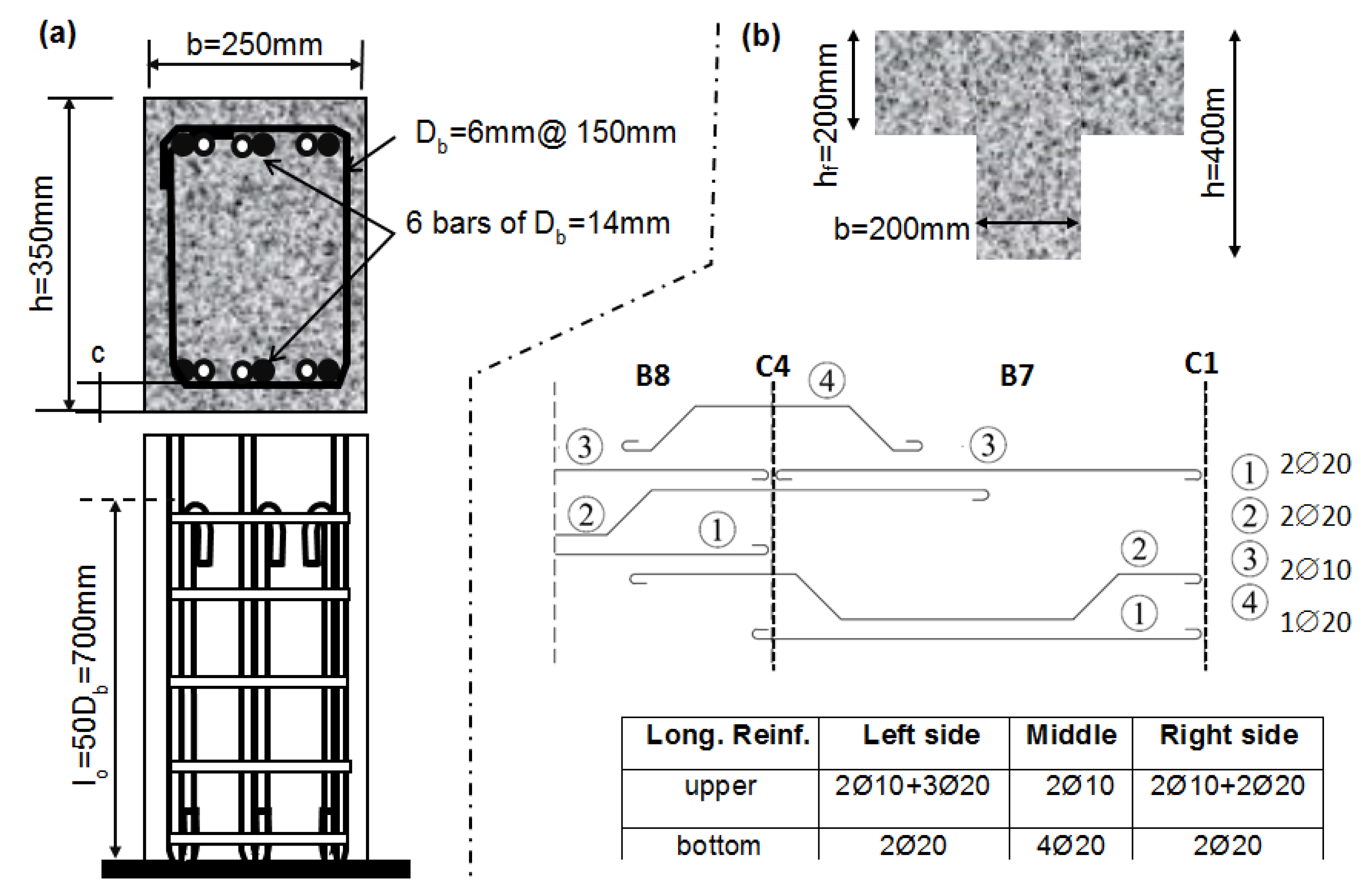
Typical columns have a rectangular cross section with h = 350 mm and b = 250 mm, reinforced internally with six longitudinal bars of diameter Db = 14 mm, with clear cover c = 20 mm and effective depth d about the strong axis x being d = 350 − 20 − 0.5 × 20 = 323 mm. The reinforcing ratio is ρl = As/bh = 1.06%. The columns’ transverse reinforcement comprises stirrups of Db,st = 6 mm at 150 mm centres, all anchored with 90° hooks at the ends (Figure 2a); this shear reinforcement is of poor effectiveness both due to its magnitude and anchorage detailing. The lap splicing length is developed at the bottom of the column and consists of a straight part lo = 50 Db = 700 mm with end hook (Figure 2a). In this case, the effective splice length is artificially increased by 12.5 Db aiming to account for the influence of the hook (thus lo = 62.5 Db = 875 mm). All beams have a cross section height of h = 400 mm (including the flange thickness that is equal to the slab thickness, hslab = 200 mm) and breadth b = 200 mm, reinforced as presented in Figure 2b. The beam transverse reinforcement comprises stirrups of Db,st = 6 mm at 250 mm centres anchored with 90° hooks at the ends. The materials mean strength is considered for the assessment procedure [28]: the mean in situ cylindrical concrete compressive strength is fcm = 16 MPa (by following [29]). The longitudinal reinforcement is ribbed steel StIV with an average yield strength based on tests of extracted samples fys = 500 MPa. Transverse reinforcement is smooth steel StI with an average yield strength based on tests of extracted samples fyw = 240 MPa.

3.2. Assessment of Pilotis Columns

In a pilotis-type frame structure (i.e., common practice in Greece and southern countries in Europe) infill walls are absent in the ground storey bays to allow for parking or shop windows. The lateral deformation imposed by the seismic loading localizes in the ground floor due to the low stiffness compared to that of the upper floors, thus acting as a soft storey. Therefore, an assessment of ground floor columns is critical since earthquake events have revealed that ground columns’ failure precedes that of beams (for beams a similar assessment procedure may be followed, not presented here due to page limitations).

3.2.1. Slenderness

A first step is to check the slenderness of the columns. The total gravity load of each floor, Wfloor, is calculated by the seismic combination, G + 0.3 Q, where G stands for the total dead load (25 kN/m3 of reinforced concrete for the slab of thickness hf = 0.2 m and additional 2 kN/m2) and Q is the total live load (3.5 kN/m2), hence, Wfloor = plan area·(Ghf + 0.3 Q) = 120 m2·(25 × 0.2 + 2 + 0.3 × 3.5) = 966 kN whereas the total weight carried by the building’s ground floor columns is Wtot = 3 × 966 = 2900 kN (three floors). For simplicity the weight of the external brick masonry walls of the 2nd and 3rd floor was not considered in the building mass because it represents about 5–10% of the weight of the r.c. elements. For example, the masonry weight per floor is Wmasonry ≈ 165 kN (see the detailed calculation in Table A1 of Appendix A—the same is valid for the next calculations where it is deemed necessary). Thus, the total masonry weight is 330 kN—this is an upper limit since the calculation does not consider any openings. Each ground column undertakes part of the total axial load after multiplying Wtot by the ratio of the tributary area (i.e., the light hatched area as per column C1 in Figure 1a) to the total floor area. The values of axial loads NEd along with the corresponding axial load ratios, vEd = NEd/(bhfcm) are NEd = 181.3 kN—vEd = 0.13 for the corner columns C1/3/7/9, and NEd = 362.5 kN—vEd = 0.26 for all the peripheral columns C2/4/6/8. The central column C5, by having NEd = 725 kN—vEd = 0.52, is prone to crushing before yielding due to the high axial load. In order to reduce vEd below 0.4, thus securing a dominant flexural response, the increase in the cross-section dimensions is required. The slenderness effect is taken into consideration by following the procedure of ACI 318-19 [30]. The radius of gyration for the cross section of the column with respect to the weak axis y-y (Figure 1a) is i = √(Ig/Ag) ≈ 0.3 b = 75 mm and the associated slenderness is λ = (βo∙H)/i = 36 > λlim = max{25; 15/√vEd = 20.8} = 25. The reduction in slenderness is achieved by increasing the cross section to hnew = 450 mm and bnew = 350 mm. The new calculations are: vEdnew = 0.29, inew ≈ 0.3 bnew = 105 mm and λnew = 25.7 < λlim = max{25; 27.9} = 27.9. Note that vEdnew = 0.29 is an upper value given that the increase in the cross section dimensions is usually implemented by using concrete of higher quality.

3.2.2. Deformation and Strength Indices from Flexure

The strength and deformation capacity were assessed as per the response of the building in y-y direction (strong axis: bending about x-x in Figure 1a). The corner columns are expected to yield first due to the lower axial load. The central column C5 is susceptible to crushing before yielding due to the high axial load. For lightly reinforced concrete elements, the curvature at the onset of tension reinforcement yielding ϕy is approximated ϕy = (2εsy)/h = 2 × 0.0025/350 = 0.0143/m, common for all columns. The moment at yielding as per the point of action of the concrete force can be approximated by Equation (1):
My = Asl,1∙fym∙jd + NEd(0.5 h − 0.4 × 0.25∙d)
where jd = 0.85 d is the internal lever arm between tensile force of bottom steel reinforcement and concrete compressive force and Asl,1 = 3 × π × 142/4 = 462 mm2 is the area of tensile reinforcement. The implementation of Equation (1) for corner columns (NEd = 181.3 kN) results to My ≈ 89 kNm and for peripheral columns (NEd = 362.5 kN) to My ≈ 115 kNm. A more precise calculation of curvature and moment at yielding can be deduced from cross section analysis by using Response2000 [31], where for corner columns ϕy = 0.0128/m, My = 90 kNm and for peripheral columns ϕy = 0.0148/m, My = 109 kNm. The two procedures for definition of ϕy, My result to similar values.
The curvature at ultimate ϕu = εcu/(ξd), at concrete crushing strain εcu = 0.0035, may be found by using the graph of Figure 3 (similar graphs were derived in [32]): for symmetrically reinforced cross section (present case), the normalized compression zone ξ = x/d (d = 323 mm) is plotted against the total longitudinal reinforcing ratio ρl for several axial load ratios. This graph was deduced at yielding of tensile reinforcement; aiming to address the fact that at ultimate the compressive zone x becomes shorter, a reduction factor 0.9 is also applied to ξ value. Thus, for ρl = 1.06% for corner columns (vEd = 0.13) is ξ = 0.24 and ϕu = 0.0035/(0.9 × 0.24 × 323) = 0.05/m and for peripheral (vEd = 0.26) is ξ = 0.27 and ϕu = 0.044/m. All useful values of the assessment are summarized in Table 1.
The secant to yield effective stiffness of the columns is given as EI = Myy. Hence, for the two groups of columns: (i) EI = 89/0.0143 ≈ 6250 kNm2 for corner columns, (ii) EI = 115/0.0143 ≈ 8050 kNm2 for peripheral one. For concrete grade C16/20 the Young Modulus is E = 29 GPa, the moment of inertia of uncracked section is I = bh3/12 = 8.93 × 108 mm4 (no consideration of internal reinforcement) thus the elastic stiffness is EIel ≈ 25,900 kNm2. This is near threefold the effective values above (in pushover analysis cross sections are assumed cracked, hence 50% of the elastic value is used, EIcr = 50%EIel = 12,950 kNm2). The secant to yield translational stiffness of the columns is calculated by using K = 12 EI/H3. For corner columns K = 12 × 6250/2.73 = 3810 kNm−1 and for peripheral columns K ≈ 4910 kNm−1 whereas the elastic and that of the cracked cross section values are 15,790 kNm−1 and 7895 kNm−1, respectively. By comparing values of K, the order of magnitude of the error for the estimated translational stiffness may be large, depending on the adopted approach. This difference has a great impact on the structure period of vibration, and thus on the maximum displacement that is going to be developed during the earthquake. Later, in Section 4, the secant to yield translation stiffness is used in defining the effective translational period Teff of the building (Table 1).
The chord rotation at yielding is approximated as θy = (ϕyH)/6 = (0.0143 × 2.7)/6 = 0.64%. A more detailed expression of this property is [33]:
θy = 1/3ϕy(avz + LV) + 0.0014(1 + 1.5 h/LV) + 0.125ϕyDb fsy)/√fcm
with avz = 0 (it is assumed that shear cracking is not expected to precede flexural yielding), LV = 1350 mm (i.e., half the column clear height), h = 350 mm, Db = 14 mm, fsy = 500 MPa and fcm = 16 MPa. Equation (2) results to θy = 1.15% that is almost double of the simplified estimation (θy = 0.64%). However, the most conservative value θy = 0.64% is used in the following calculations because it is testified in relevant tests on substandard columns as a lower bound magnitude [34].
The ultimate chord rotation θu is estimated by following the three alternative procedures presented in chapter 8 of [4] and are summarized in Table 1. More specifically:
(a)
From basic mechanics:
θu = 1/γely + (ϕu − ϕy) lpl (1 − 0.5 lpl/LV)]
where γel is equal to 1.5 for primary members, θy = 0.64%, ϕu is the ultimate curvature of the end section evaluated by assigning the concrete ultimate strain εcu = 0.0035 (values are shown in Table 1). The plastic hinge length lpl can be estimated from three alternatives, as:
lpl = 0.1 LV + 0.17 h + 0.24 (Dbfsy)/√fcm
lpl = 0.2 h [1 + 1/3 min (9,LV/h)]
lpl = 0.5 d
Their implementation results to lpl(3a) = 615 mm or lpl(3b) = 160 mm or lpl(3c) = 161.5 mm, respectively. Note that Equation (3b) considers cyclic loading and Equation (3c) is a simple definition of lpl for members with old type detailing. The results of Equation (3b,c) coincide. The difference in results for lpl obtained from Equation (3a–c) is considerably high and affects the estimations of the elements’ ductility. For example, for corner columns θu(lpl = 615 mm) = 1.6% or θu(lpl = 160 mm) = 0.8%. The corresponding rotation ductility is μθ = θuy = 1.6/0.64 = 2.4 or μθ = 0.8/0.64 = 1.2. Apparently, the results in Table 1 for lpl = 160 mm suggest that all columns—except of the middle one—fail close to yielding demonstrating no ductility. For lpl = 615 mm all columns demonstrate adequate ductility in the order of 2.
(b)
Empirically, by following the proposed Equation (4a,b):
μϕ = 0.45 εcu,c/(εsyνEd) for νEd ≥ 0.2 and μϕ = 0.45 εcu,csy × h/ξd for νEd < 0.2
μθ = θuy = μΔ = 0.5(μϕ + 1)
where, term ξ from Table 1 should be multiplied with 0.9 (as previously explained), εcu,c = 0.0035, εsy = 0.0025 and θy = ϕyH/6 = εsy(H/h)/3 = 0.64%. The μθ value shall be multiplied by 1.5 to account for the contribution of reinforcement pullout to the rotation capacity. Implementing Equation (4a,b) for example for columns C1/3/7/9 (νEd = 0.13 < 0.2), result in μϕ = 3.16 and μθ = 1.5 × [0.5 × (3.16 + 1)] = 3.1 and θu =3.1∙0.64% = 2%. This value of θu [Table 1, column denoted as (b)] is close to that calculated above in procedure (a) when using lpl = 615 mm from Equation (3a).
(c)
The value of the plastic part of the chord rotation capacity of concrete members under cyclic loading is given by the following calibrated Equation (5) (from [33]):
θ u pl = 1 γ el 0.0185 × 0.48 1 + α sl 1.6 0.25 ν max 0.01 ,   ω max 0.01 ,   ω 0.3 f c 0.2 L V h 0.35 × 25 α w ρ wy f yw f c 1.275 100 ρ d
where θuy + θ u pl y = 0.64%). The implementation of this expression is demonstrated for corner columns C1/3/7/9: γel = 1.8, αsl = 1 because slippage of vertical bars from their anchorage or lap-splice at the lower end of the column is physically possible (presence of splices), ν = 0.13, ω = ρs1fsy/fc = 0.53% × 500/16 = 0.165, and ω’ (even if ρs1 = ρs2 = 0.5ρl = 0.53%) is taken double of ω due to the presence of splices, fc = 16 MPa, fsy = 500 MPa, LV = 1350 mm, h = 350 mm, ρd = 0 (absence of diagonal reinforcement), ρwy = Asy/(shb) = 2 × (π × 62/4)/(150 × 250) = 0.15% (ratio of transverse steel parallel to the direction of loading, here y-direction), αw = 0.14 (confinement effectiveness factor, limited contribution because stirrups are sparse) and fyw = 240 MPa. This results in θ u pl = 2.33% and θu = 0.64% + 2.33% ≈ 3%. For the peripheral columns the calculations lead to θu = 0.64% + 1.95% = 3.1%. It is important to note that in this procedure (c) the presence of splice lo in the vicinity of plastic hinge length deteriorates the plastic rotation when lo < lou,min and then the total rotation capacity should be multiplied by lo/lou,min; term lou,min is given by Equation (5a,b):
  l ou , min = D b f sy 1.05 + 14.5 a l ρ wy f yw / f c f c
al = (1 − sh/(2bo)) × (1 − sh/(2ho)) × nrestr/ntot
Their implementation results to al = 0.32 and lou,min =1513 m. The hooked splice may be assumed as sufficient detailing for earthquake resistance (no need to divide with 1.2). Because lo = 875 mm < lou,min = 1513 mm, thus the ultimate rotation for the corner columns is θu = 875/1513 × 3% = 1.7% and for peripheral columns, θu = 875/1513 × 3.1% = 1.8%.
The calculations of θu deduced by the three procedures (a–c), led to µθ results higher than 2, however when considering a narrow plastic length, they may receive values close to 1. The demonstration of the three procedures aims at highlighting the easiness or complexity each one encompasses as per its implementation.

3.2.3. Brittle Mechanisms: Shear and Lap-Splices

The calculations in Section 3.2.2 for determining the flexural response of the ground storey columns ignored the columns’ shear capacity. The preceding calculations are meaningful provided the columns are able to develop the lateral force Vfl that corresponds to flexural capacity, i.e., Vfl = My/LV. Thus, for corner columns Vfl = 89/1.35 ≈ 66 kN and for peripheral Vfl = 115/1.35 ≈ 85 kN. Note that Vfl should be multiplied by a safety factor >1 aiming to account for the over-strength of columns. More specifically, in accordance with EN1998-1 [35], for medium ductility r.c. buildings (DCM), the over-strength for beams and columns may be found by the product of the flexural capacity with (i) the material safety factor 1.15 for steel, (ii) a factor equal to 1.2 due to design-action effects at the end sections of critical regions, and (iii) a factor equal to 1 and 1.1 due to steel strain hardening for beams and columns, respectively. Thus, for columns the overstrength factor is 1.15 × 1.2 × 1.1 ≈ 1.5. The shear capacity of the columns is given by Equation (6) (from [33]):
VRd,o = 1/γel {(h − x)/(2LV)·min(N, 0.55Acfc) + [1 − 0.05min(5,μθpl)](VRd,c + VRd,s)}
VRd,c = 0.41√(fc)b × x
VRd,s = ρsw,ybohofy,st = Asy/(shbo)bohofy,st
where γel = 1.15, x = ξd (ξ from Table 1, multiplied also with the correction factor 0.9 as explained before). Applying Equation (6b,c), for corner columns result to VRd,c ≈ 29 kN, for peripheral to VRd,c ≈ 32 kN and VRd,s = 28 kN. For the definition of μθpl = (θu − θy)/θy = μθ − 1, among procedures (a–c) above, procedure (b) is chosen because it results to a more conservative estimation of VRd,o. Thus for the corner columns the term [1 − 0.05 min(5,μθpl)] in Equation (6a) is [1 − 0.05 min(5,3.1−1)] = 0.89 and for peripheral columns is 0.92 (μθpl = 2.6 − 1 = 1.6). Next, Equation (6a) is implemented: for corner columns is VRd,o ≈ 60 kN < 1.5 Vfl = 1.5 × 66 = 99 kN and for peripheral VRd,o = 80 kN < 1.5 Vfl = 1.5 × 85 ≈ 128 kN.
It may conclude that both corner and peripheral columns will fail in shear near yielding at almost the same drift (θyVRd,o/Vfl: for corner columns is 0.64% × 60/66 = 0.59% and for peripheral 0.64% × 80/85 = 0.6%).
Another concern is whether the available splice length lo suffices for the reinforcing bars to develop their yielding strength. The available bond strength is given by Equation (7):
τb = 2μfr/(πDb) × [2cfctk + 0.33 (Ast fy,st)/(Nbs)]
and yielding is secured when τb ≥ γelDbfsy/(4lo). Values for the parameters are: μfr = 1, Db = 14 mm, fctk = 0.33 fcm0.5 = 0.33 × 160.5 = 1.3 MPa, c = 20 mm, Ast = 2 × π × 62/4 = 56.5 mm2, fy,st = 240 MPa, Nb = 3 bar pairs, s = 150 mm, γel = 1.15, fsy = 500 MPa, thus Equation (7) yields to τb = 2.82 MPa. For a splice with a hook (lo = 875 mm) is τb = 2.8 MPa > γelDbfsy/(4lo) = 2.3 MPa, thus lap splice suffices longitudinal reinforcement yielding, but after that milestone (where µθ > 1) cover cracking is anticipated; this implication diminishes cover contribution (i.e., 2cfctk ≈ 0) in defining bond strength thus a splice failure is also anticipated.
From the preceding assessment analysis, it may be concluded that the ground columns may suffer shear failure before any yielding of the longitudinal reinforcement that occurs at a drift of 0.6%; the latter corresponds to lateral displacement at the top of the ground storey Δ = 0.6% × 2.7 m = 16 mm. [Note: If a straight splice without hook detailing was used, then lap splice failure is also anticipated for both the peripheral and the corner columns before yielding].

4. Global Strengthening Requirements

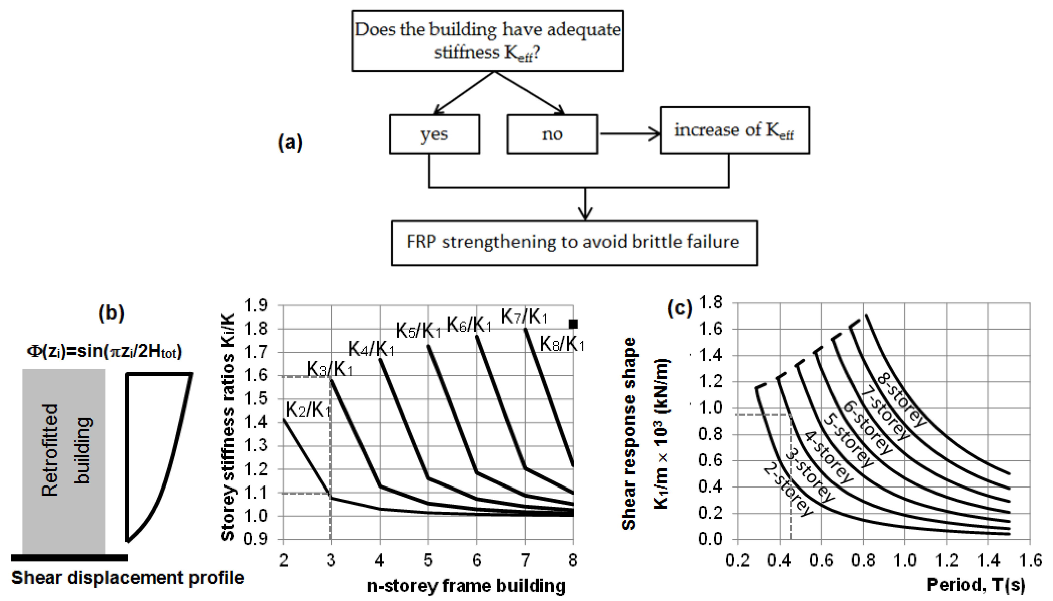
The strengthening of the existing building should consider whether the available effective stiffness, Keff, suffices to resist the seismic demand or if there is need to moderate, i.e., the drift demand. In the latter case, the retrofit solution should include global intervention measures to increase Keff along with local interventions like FRP jacketing for alleviating brittle modes of failure (Figure 4a). Note that by increasing Keff the demand may be reduced in two different ways: (a) a higher effective stiffness results in a lower predominant period tending towards the left in the displacement spectrum, and (b) through a more uniform distribution of deformation demand in the structure, which secures that the magnitude of deformation demanded by individual members is lowered.
The necessary calculations for global measures are based on Appendix 8.2 of [4]. More specifically, the total building mass is M = 290 tonnes. The effective translational period Teff is calculated based on the secant to yield sectional analysis for the definition of individual column translational stiffness K. By assuming that the building has a soft first storey (i.e., pilotis-type), then practically all lateral translation is concentrated in the ground storey (Keff = ∑i=1nKi ΔΦi2 = K1 × 12 = K1). Thus, the translational stiffness against seismic sway of the ground storey is (direction y-y): Keff ≈ 38,690 kN/m. Note that column’s C5 stiffness was taken conservatively as the least among the other two groups. Its reinforcement does not reach yielding due to the applied high axial load. Therefore, the effective period is Teff = 2π√(M/Keff) = 2 × 3.14 × √(290/38,690) = 0.54 s. The empirical reference value Tref in EN 1998-1 [35] is Tref = 0.075 Htot3/4 = 0.075 × 93/4 = 0.39 s. Because Teff/Tref =0.54/0.39 = 1.4, Teff exceeds by more than 25% the empirical Tref. Thus, Keff should be increased to lower Teff to an acceptable range of values, i.e., 0.4–0.45 s for a three-storey building.
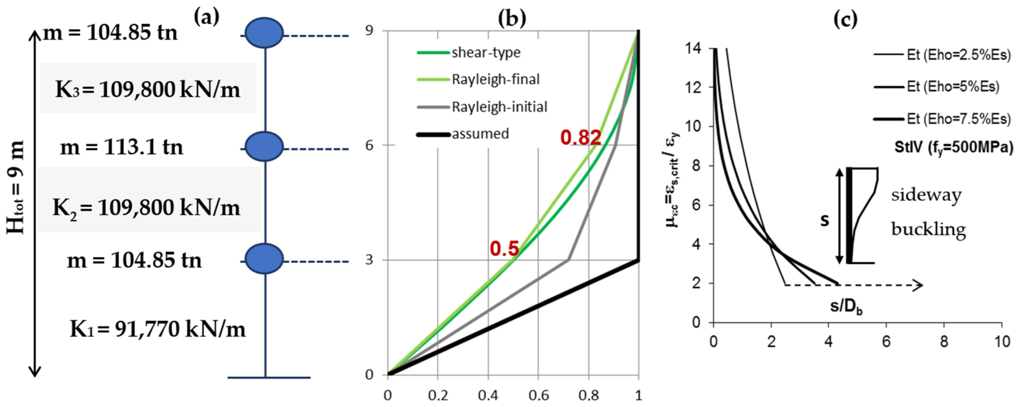
The target or improved period, Ttrg, of the retrofitted structure may be selected based on experience, as a value between Tref and the initial Teff. A note of caution is that the cost of the intervention increases as Ttrg is reduced getting closer to Tref. Besides, an increase in Keff is required aiming at modifying the lateral deflection shape (fundamental response shape) due to localization of deformation at the ground floor columns (i.e., the assumed in Figure 5b). For the seismic assessment of the building, the peak ground acceleration was considered PGA = 0.24 g and the soil class as B. For Teff = 0.54 s, the elastic spectral displacement demand is estimated from Equation (8) for TC ≤ T ≤ TD (from [35]):
Sd (T) = ag Sηβo (TCT)/40
where S = 1.2 (soil class B), TC = 0.5 s, TD = 2 s, ag = 0.24 g, η = 1 (ξ = 5%) and βo = 2.5, hence Sd = 0.048 m. The elastic displacement Sd will induce a lateral drift in the pilotis θ = Sd/H = 0.048/2.7 ≈ 1.8% which corresponds to drift or displacement ductility demand of μθ = μΔ = 1.8/0.64 = 2.8. According to Table 1, and after the implementation of only local measures to alleviate the brittle shear failure, the drift supply by considering the most conservative procedure a is lower than the demand for all columns. The reduction in the drift demand along with the improvement of the deflection shape of the pilotis-type building requires the increase in pilotis stiffness (i.e., adoption global intervention measures) before any application of FRP jacketing (local measures).
The selection of a shear-type drift distribution along the building’s height (Figure 5b) reduces the required intervention because a soft storey formation may be re-engineered towards this option for moderate improvement. By using the charts of Figure 4b,c result in the following target values for the storey stiffness ratios Ki/K1: K2/K1 = 1.1 and K3/K1 = 1.6 (see the dashed lines in Figure 4b, K1 stands for the ground floor or first floor). For the chosen target period Ttrg = 0.45 s and by using Figure 4c, the required ground storey stiffness is K1/m1 = 950 kN/m, which once multiplied with storey mass m1 = 96.6 tn results in K1 = 91,770 kN/m, also, K2 = 1.1 × 91,770 ≈ 100,950 kN/m and K3 = 1.6 × 91,770 ≈ 146,830 kN/m for the 2nd and 3rd floor, respectively. The target stiffness value of the ground storey, K1 = 91,770 kN/m, is much larger than the available Keff = 38,690 kN/m. Such a stiffness increase in ground storey may be achieved partly by the need to increase the central column cross section due to slenderness effect and by adding metallic cross bracings in the direction of the seismic action under consideration (here the direction is y-y).
The central column of increased cross section (350 × 450 mm) is assumed as being pinned at the base with elastic stiffness KC5,new = 3EI/H3 = 11,748 kN/m (the initial value was 3810 kN/m). The required cross braces stiffness is deduced as: ΣKX = K1 − KC5,new − 4 corner columns × 3810 kN/m − 4 peripheral columns × 4910 kN/m ≈ 45,140 kN/m. The span of each brace is L = 5 m − 1.5 × 0.35 m = 4.475 m and ϕ = arctan(hst,cl/L) = 0.6 thus ϕ = 31° (hst,cl = 2.7 m). The length of the brace diagonals is D = √(44752 + 27002) = 5226 mm. The stiffness of braces is (modulus of elasticity for cast steel sections, Es = 150,000 MPa): ΣKX = 45,140 kN/m =2EsAbr/Dcos2ϕ = 2 × 150,000 × Abr/5226 × cos2(31°) thus Abr ≈ 1100 mm2. By adding two braces symmetrically (i.e., by connecting columns C1–C4 and C6–C9), then each brace should have total cross section Abr = 650 mm2.
After the increase in the pilotis stiffness under the requirement of a shear-type deflection shape using the charts of Figure 4b, one could validate this simple solution by performing the Rayleigh iterative method and considering the stiffness of the exterior infill walls of the upper floors. More specifically, in each of the upper two floors, for two exterior solid walls in y-y direction of a total cross section area Aw = 2 × (10 m − 3 × 0.35 m) × 0.12 m ≈ 2.15 m2 or ρmw = Aw/(Afloor = 120 m2) ≈ 0.018 and for hi = 2.7 m, fbc = 5 MPa, fmc = 5 MPa (each is divided by γm = 1.5), and μymw = 2.5, θymw = 0.15%, then the masonry wall stiffness in each floor is: Kmw ≈ Afloor/hi × (0.1fbc0.7fmc0.3)/(μymwθymw) × ρmw,i ≈ 71,100 kN/m. The available effective stiffness of the 2nd and 3rd floor are then: K2 = K3 = Keff + Kmw = 38,690 + 71,100 ≈ 109,800 kN/m (Figure 5a). Because the available magnitudes K2 and K3 are higher than or close to the required for the chosen shear-type response of the building (i.e., K2 = 100,950 kN/m and K3 = 146,830 kN/m), there is no need for global measures in these floors. For the Rayleigh iterative method, the floor mass (i.e., 96.6 tonnes) is increased by adding a share of the total masonry weight Wmasonry = 33 tonnes; thus Wmasonry was distributed as ¼ in each of the ground and the 3rd floor and ½ in the 2nd floor. After such analysis, the deflection shape presented in Figure 5b was obtained (the light green coloured curve titled Rayleigh-final) and is very close to the shear-type on which the addition of stiffness was based. Moreover, from this analysis the calculated period is found 0.46 s, very close to the target value Ttrg = 0.45 s. In addition, the initially assumed lateral deflection shape and the initial approximated shape by using the Rayleigh method are plotted in Figure 5b for comparison reasons (the masonry mass and stiffness of the upper floors is considered).
For the selected period Ttrg = 0.45 s (<TC = 0.5 s), the elastic spectral displacement demand is estimated from Equation (9) (from [35]):
Sd (T) = ag SηβoT2/40
where ag = 0.24 g, S = 1.2 (soil class B), η = 1 (ξ = 5%) and βo = 2.5, thus Sd = 0.036 m. Considering that this displacement will be increased by about 20% when transferring from the spectrum (Equivalent Single Degree of Freedom) to the actual structure (Multi-Degree of Freedom), then, the relative drift demand at the ground storey (ΔΦ = 0.5, Figure 5b) is θdem= 1.2 × 0.5 × Sd/H = 0.8%, which corresponds to a ductility demand of μθ = μΔ= 0.80%/0.64% = 1.25. This demand is very close to the supply when a short plastic hinge length is considered [procedure (a) in Table 1]. To improve ductility and to alleviate premature shear failure, FRP jacketing is required.

5. Local Strengthening through FRP Jacketing

The objective is to remove, through FRP jacketing, brittle failure modes so that the flexural capacity of columns can be fully developed. The design methodology adopted follows the procedure described in Chapter 8 of [4,5]. FRP confinement is applied as to enhance (i) displacement ductility, (ii) shear strength, and additionally, to prevent failure due (iii) buckling of steel longitudinal bars. For the needs of the current example, a generic carbon FRP fabric with the following mechanical properties was selected for column and beam retrofitting: thickness to = 0.12 mm, modulus of elasticity: Ef = 165,000 MPa, ultimate tensile stress: ffu = 2970 MPa and ultimate strain εfuk = 0.018. The design tensile strain εfu,h in the FRP layer shall not exceed the limit: εfu,h= η1·η2·η3·εfukf where γf = 1.5 for fully wrapped FRP arrangement (i.e., the ground floor RC frames do not accommodate any masonry). Factors η1, η2, η3 are considered as follows:
-
Factor η1 accounts for the radius of chamfer R (= c + 0.5Db = 20 + 7 = 27 mm), at the corners of the member: η1 = 0.25 + 2(2R + Db)/h′ = 0.25 + 2(2 × 27 + 14)/(350 − 2 × 27) = 0.71 < 1 (h′ is the straight part of the largest cross section side).
-
Factor η2 = 1 accounts for the sufficiency of the wrap development length: the straight parts of the cross section sides h′ ≈ 300 mm and b′ ≈ 200 mm suffice to accommodate the minimum anchorage length of the external FRP layer lbmin = 0.5π√(Ef × to × soa)= 0.5π√(165,000 × 0.12 × 0.5/5) ≈ 70 mm (so and τa are slip and bond strength values, provided by the resin manufacturer); to this end the external layer of the FRP jacket can be anchored over the column’s shorter side.
-
Factor η3 = 1 for fully wrapped jacket (considers the redundancy of the jacket against debonding).
Accordingly, the design tensile strain εfu,h in the FRP layer is εfu,h = η1·η2·η3·εfu,h= 0.71 × 1 × 1 × 0.018/1.5 = 0.0085.
Given the required displacement ductility (μθ = 1.25) from Section 4, the associated curvature ductility is μϕ = 2μθ − 1 = 2 × 1.25 − 1 = 1.5. The maximum compression strain demand is εcu,c = 2.2μϕεsyνEd [form Equation (4a)]. For the corner columns (vEd = 0.13) εcu,c = 2.2 × 1.5 × 0.0025 × 0.13 = 0.0011 < 0.0035 and for the peripheral columns (vEd = 0.26) εcu,c = 0.0021 < 0.0035. From these calculations, it is concluded that there is no need for confinement of concrete through closed FRP jackets to meet its strain demands in the compression zone resulting from the displacement ductility calculation.
According to Section 3, flexural response dominates when the shear strength VRd exceeds 1.5 Vfl. For the simplicity of the following calculations it is taken as 1.5 Vfl = max(1.5 Vfl,corner,1.5 Vfl,peripheral) ≈ 128 kN and also the available VRd,o = min(VRd,o,corner,VRd,o,peripheral) = 60 kN. The difference ΔV = 1.5 Vfl − VRd,o = 68 kN will be resisted by FRP closed-type jacketing as ΔV = VRd,f = (2tf/b) × bh × Ef × εfu,h, which it results to tf = 0.07 mm < to = 0.12 mm. A single layer suffices for shear strengthening along the column’s height.
For the lap-splices, even if the available bond strength τb = 2.82 MPa [from Equation (7)] due to cover and stirrups contributions suffices for bar yielding [τb = 2.82 MPa > γelDbfsy/(4lo) = 2.3 MPa], however it is reduced after that milestone because cover is cracked [term 2cfctk in Equation (7) is set equal to 0]. The contribution of FRP jacketing in restoring the bond strength to the yielding limit is given by Equation (10):
τb = 2μfr/(πDb)[0.33Astfy,st/(Ns) + 2tf Efεf,sl)/Nb]
thus, for Db = 14 mm, μfr = 1, Nb = 3, εf,sl = 0.0015, tf = nto, Ast = 2 × π × 62/4 = 56.5 mm2, fy,st = 240 MPa and s = 150 mm Equation (10) results to tf = 0.25 = nto = n × 0.12, or n = 2 layers needed to wrap the splice region of lo = 700 mm, that is developed at the bottom of the column.
To eliminate potential buckling of compressive bars, given the required curvature ductility, μϕ = 1.5, the compression strain demand is εcu,c < 0.0035 for both the corner and the peripheral columns (as previously was checked from εcu,c =2.2μϕεsyνEd). From the buckling curve of Figure 5c (case StIV-fy = 500 MPa and sideway buckling) and for s/Db =150/14 ≈ 11, the strain at which the bar will become unstable is μεc ≈ 2 = εs,crits,y thus εs,crit = 2 × 0.0025 = 0.005. Hence, for the estimation of the required jacket confinement, it must be ensured that εcu,c ≥ max(εcu,c = 0.0035, εs,crit = 0.005) = 0.005. Equation (11a–c) correlate term εcu,c with the FRP jacketing:
εcu,c = εcu + 0.075[ζ × (αf ρfvEf εfu,h + αwρsvfy,st)/fc − 0.1] ≥ εcu
αf ≈ 1 − ((b − 2R)2 + (h − 2R)2)/(3bh)
ρfv = 2tf(h + b))/(hb)
with εcu = 0.0035, ζ = 1 (for εcu,c ≤ 0.01), αf = 0.56, αw = 0.15, ρsv = 0.00314 and εfu,h = 0.0085 (as previously calculated); thus Equation (11a) results to ρfv = 0.0023 and ρfv = 2tf (b + h)/(bh), which in turn corresponds to n = 2 layers along the critical regions of all columns, top and bottom, of length lpl = 615 mm (for simplicity of the intervention this length is rounded to 600 mm).
Given the above calculations for elimination of premature buckling and splice failure, the applied jacketing (2 layers result to tf = 0.24 mm and thus to ρfv = 0.0033) offers a limited displacement ductility. This is testified through Equation (12):
µΔ = 1.3 + 12.4 × (0.5 × αfρfvEfεfu,h/fc − 0.1) ≥ 1.3
Its implementation results to µΔ = 1.06 ≥ 1.3 thus µΔ = 1.3. This supply suffices against the required value (as previously calculated µΔ = 1.25).
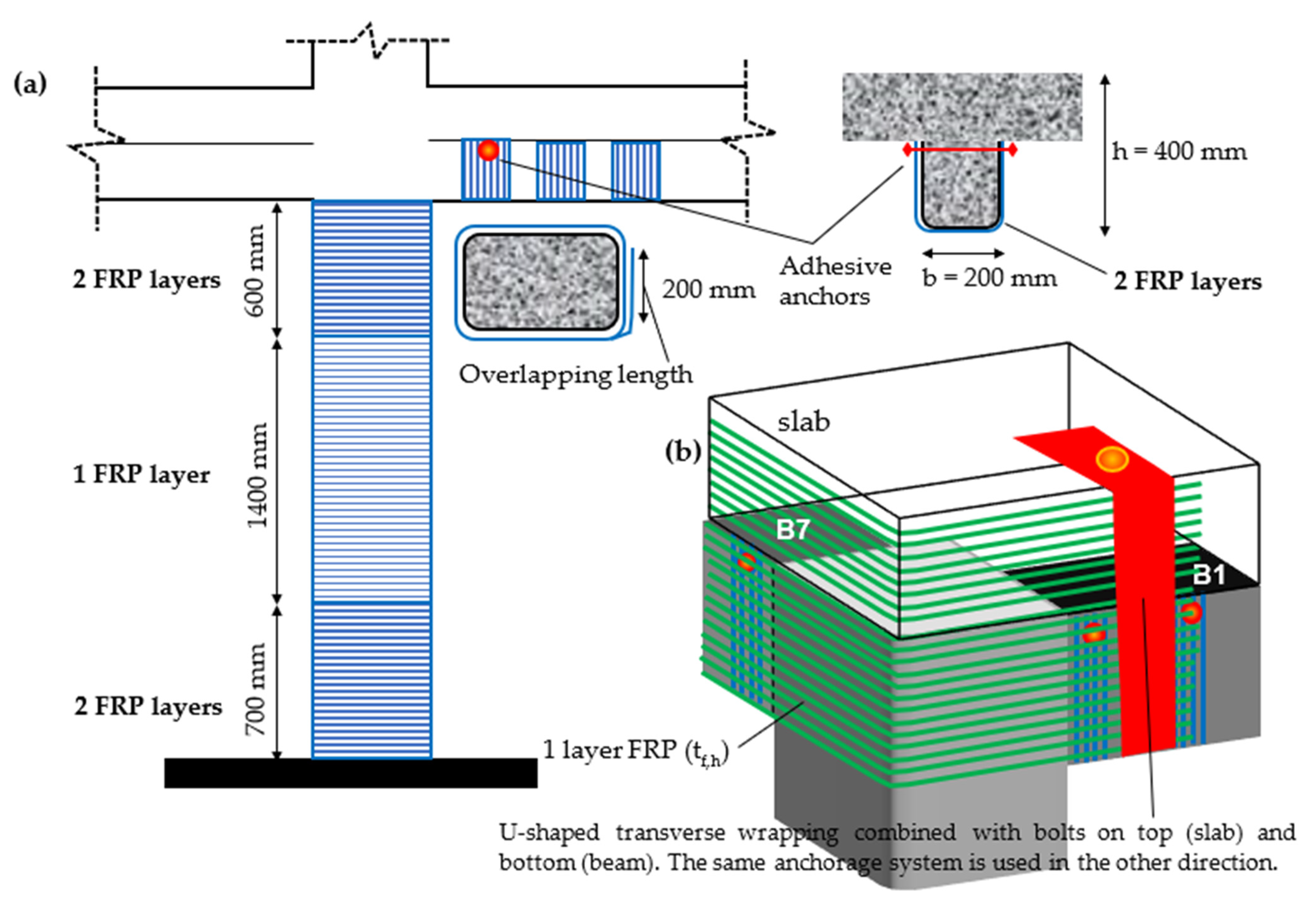
The FRP strengthening of the ground storey columns (except C5) is summarized as follows: a single CFRP layer is wrapped along the height of each column to alleviate shear failure, one additional CFRP layer is wrapped at the lower 700 mm of each column to strengthen the splice region, one additional CFRP layer is wrapped at the upper 600 mm of each column to alleviate compressive bar buckling (Figure 6a). Column C5 does not require any FRP intervention because the increase in its cross-section size is implemented through reinforced concrete jacketing. (Note: For beams, by following similar procedure, FRP U-shaped jacketing of two-layer strips of width 100 mm and spacing 100 mm along the element full length is required along with special details in the ends in order to secure the jacket against debonding, e.g., adhesive anchors, see Chapter 6 in [4], Figure 6a).

Beam-Column Joint Strengthening

External beam-column joints are not laterally supported on four sides by beams, hence require horizontal shear reinforcement to prevent deterioration due to cracking induced by the high shear stress demand. This demand is the result of the steep moment gradients as they facilitate reversal of moment from one face of the member to the other. In old structures, r.c. beam-column joints rarely had in their body horizontal stirrups. So, it is deemed necessary to retrofit such a critical element of the structure.
As it is observed in the plan layout of Figure 1a, T- and L-shaped (knee or corner) joints exist. The strengthening design procedure is presented in detail for the L-shaped joint B1-C1-B7 of the ground storey; apparently all other L-shaped joints of the ground floor follow the same requirements. It is noted that in Chapter 8 of fib Bulletin 90 [4] two design approaches are presented. In this example, Approach 1 is implemented aiming to determine the required amount of horizontal FRP reinforcement through its function as added shear reinforcement in the joint panel. Approach 1 generally leads to significant amount of FRP reinforcement because, in the interest of conservatism, neglects any confining contribution, which could in turn lead to a retrofit inferior to expectations.
The first step is to calculate the sums of yield moments in the beams and in the columns framing into the joint. Hence, ΣMyb is the sum of yield moments of the beams that frame into the joint and ΣMyc is the sum of yield moments of the columns that frame into the joint:
x-x direction—weak axis (C1–B1): Beam B1-left has yield moment 134 kNm. The yield moments of the column below and above the joint are 53 kNm (NEd = 181.3 kN) and 48 kNm (NEd = 120.8 kN), respectively (the cross-section analysis was performed using Response2000 [11]). Hence, ΣMyc = 53 + 48 = 101 kNm < ΣMyb = 134 kNm. By being columns weaker than beams, they define the magnitude of shear stress in the joint. Hence, the vertical shear force Vj,v is derived by following the Greek Code for Assessment and Retrofit [36], from Equation (13) as:
Vj,v = ΣMyc(1/jdc − 1/Lb,n·Hn/H) + 1/2|(Vg+ψq,b)l − (Vg+ψq,b)r|
where jdc is the internal lever arm of the column section, Hn and H are the theoretical and clear storey heights, and Lb,n is the theoretical half span of the beam. The beams are considered as fully fixed at their ends. The load from the slabs is assumed to be transferred to beam B1. Conservatively, it is assumed that the loads transferred from the slab to B1 correspond to a quarter of the area of the slab. Hence, the total linear load for the seismic combination is estimated as g = 9.75 kN⁄m, q = 4.38 kN⁄m and g + 0.3q = 11.06 kN⁄m, hence (Vg+ψq,b)l = (g + 0.3q)l/2 = 33.19 kN. Then, by implementing Equation (13) results to Vj,v = 510.8 kN. The horizontal shear force Vj,h acting in the joint is obtained from: Vj,h = Vj,v × hc/hb =510.8 × 250/400 = 319.2 kN with upper limit of: Vj,h ≤ 80% × ηfcm√(1 − vEd/η)·bjhjc where η = 0.6(1 − fck/250) = 0.58, bj = min[max(bc, bb), min(bc, bb) + hc/2] = 250 mm and hjc = 250 − 2∙d2= 250 − 2 × 27 =196 mm. Thus Vj,h = 319.2 kN < 334.4 kN.
y-y direction—strong axis (C1–B7): The yield moment of beam B7-right is 134 kNm. The yield moments of the column below and above the joint are ~90 kNm and 83 kNm: ΣMyc = 83 + 90 = 173 kNm > ΣMyb = 134 kNm. By being beams weaker than columns, they define the magnitude of shear stress in the joint. The horizontal shear force Vj,h is derived by following the Greek Code for Assessment and Retrofit [36], from Equation (14) as:
Vj,h = ΣMyb(1/jdb − 1/Hn × Lb,n/Lb)
where jdb(=0.9 d; d = 370 mm) is the internal lever arm of the beam section, Hn is the theoretical storey height, Lb,n and Lb are the theoretical and clear half span of the beams, thus Vj,h =354.4 kN with upper limit of Vj,h ≤ 80%∙ηfcm √(1 − vEd/η) × bj hjc, η = 0.6(1 − fck/250), where bj = 250 mm, η = 0.58, hjc = 350 − 2∙d2 = 350 − 2 × 27 = 296 mm. Thus, Vj,h = 354.4 kN < 505 kN.
The horizontal shear force used for the calculation of the required FRP reinforcement, where fibers are oriented in the horizontal direction, is the maximum among 319.2 kN and 354.4 kN. For such a simple plan view of a building, one could deduce that the strong axis horizontal shear force apparently prevails. [Note: Alternatively, and with respect to the strong axis, the EN 1998-1 [35] for exterior beam-column joints proposes the simplified expression Vj,h = 1.20As1fy − Vcol, where As1 is the top reinforcement of beam as As1 = 2 × π × 102/4 + 2 × π × 202/4 ≈ 785 mm2 (see Figure 2b) fy = 500 MPa and Vcol the shear force in the column above the joint as Vcol = My/LV = 83/1.35 ≈ 62 kN hence Vj,h ≈ 410 kN, which should be lower than 80%∙ηfcm√(1 − vEd/η)·bjhjc = 505 kN. This approach increases the demand for FRP by almost 55 kN in comparison with what the most recent Code [36] deduces].
Prefabricated Carbon Fiber Reinforced Polymer (CFRP) plates will be used for the beam-column joint strengthening. An essential requirement is the proper anchorage of the FRP plates, otherwise FRP strengthening should not be considered effective. Fib Bulletin 90 [2] in its Section 9.2.3 provides details about anchorage of FRP strengthening in beam-column joints. The plates selected to be used have a thickness of to = 1.4 mm, modulus of elasticity Ef = 205,000 MPa, ultimate tensile stress ffu = 3200 MPa and ultimate strain εfuk = 0.017. The design tensile strain εfd in the FRP layer shall not exceed the limit: εfd = εfukf = 0.017/3 = 0.0056 where γf = 3 for FRP anchored on brittle substrate. According to fib Bulletin 90 [4] the allowable design value of FRP tensile strain shall not be taken higher than 0.004. Hence, εfd = 0.004. The thickness, tf,h, is estimated from tf,h = γRd × Vj,h/(hb∙Ef∙εfd) as tf,h = 1.6 mm > to = 1.4 mm. Because the calculated value is very close to to, given the increased conservatism the Approach 1 has, one layer of CFRP L-shaped plate is required by covering the full height of the beams (detailing as shown in Figure 6b).

6. Conclusions

The methodology [4,5] implemented for the development of the detailed example –guide uses performance-based design criteria for the assessment and retrofitting at both local and global level. Damage is identified when the displacement demand due to earthquake excitation exceeds the displacement capacity of the individual members. The addition of externally bonded FRP reinforcement aims to remedy any deficiencies in the response of existing structural members due to the lack of seismic detailing (i.e., sparse shear reinforcement, short anchorage/splices). Global measures are adopted to modify the lateral response shape of the building and control interstorey drift.
The conceptual framework [4,5] is applied to a case study of a pilotis-type multi-story r.c. building, representative of the older construction practice in Southern Europe in the ‘70s. The building is assessed and retrofitted using externally applied FRP jacketing. Hand calculations are provided which cover in detail all the steps required for assessment and retrofitting.
The implementation of the methodology, as it is outlined in Section 2, revealed the following: as per the assessment stage (i) the order of magnitude of the error for the translational stiffness when cracked cross section (7895 kNm−1) or secant to yield (3810 kNm−1) definition is adopted may be large; this difference (here 100%) has a great impact on the estimation of the structure’s period of vibration, and thus on the maximum displacement reached during the seismic excitation; (ii) the estimated values of the deformation indices defined by using the alternative formulae included in [4,5] do not always agree with observations made on relevant experimental (the simplest formulae seem to estimate effectively the deformation indices); and (iii) the calculations of the deformation indices related to flexural response will not be realised when brittle failure modes are anticipated such as shear and lap splice which are repeatedly reported after a strong seismic event. At global level, interventions aim to lower the structure’s period close to the code reference value and to re-design the lateral response shape of the building in response to a more uniform distribution of the interstorey drift. For local interventions FRP jacketing is applied. The FRP plies required are calculated firstly to suppress all possible premature modes of failure (shear, bond, compression reinforcement buckling, exterior joints disintegration) and promote flexural response, and secondly to increase the ductility capacity in response to the seismic demand. Special attention needs to be given to the execution of the FRP application (i.e., corner rounding, special anchoring).

Author Contributions

Equal contribution by the two authors. All authors have read and agreed to the published version of the manuscript.

Funding

This research received no external funding.

Institutional Review Board Statement

Not applicable.

Informed Consent Statement

Not applicable.

Data Availability Statement

Not applicable.

Conflicts of Interest

The authors declare no conflict of interest.

Notation

Aggross area of concrete
Astotal area of longitudinal steel reinforcement
Dbdiameter of longitudinal steel reinforcement
Db,stdiameter of transverse steel reinforcement
Ecmodulus of elasticity of concrete
Efmodulus of elasticity of FRP
Esmodulus of elasticity of steel
Hclear height of column
HtotHeight of building
Kjtranslational stiffness of the column
Lvshear span
NEdAxial load of column
Mymoment at yielding
MRdothe flexural strength
Nbnumber of tensile splice pairs
Lprovprovided anchorage length of beam longitudinal reinforcement
Rradius of rounded corner
Tref/eff/trgreference, effective or target period
VRddesign shear resistance
VRd,cthe contribution of the concrete compression zone to the shear strength of the original member
VRd,fshear strength of the FRP jacket
VRd,oshear strength of the original member
VRd,sthe contribution of the web reinforcement to the shear strength of the original member
Vfllateral force at flexural strength (=MRdo/Lv)
Wtottotal weight of the building due to the seismic combination G + 0.3Q
avzthe tension shift of the bending moment diagram
bwidth of cross section (b’ after chambering)
bfwidth of FRP strip
bowidth of confined core in a column (to centerline of hoops)
cthe clear cover
deffective depth of the member
fcconcrete strength
fcmmean value of the concrete compressive strength
fctkthe concrete tensile strength
ffddesign value of the FRP tensile strength
fymmean value of the longitudinal steel yield strength, also referred as fsy
fywthe mean yield strength of the shear reinforcement, also referred as fy,st
htotal depth of the member (h’ after chamfering)
hslabtotal depth of the slab
lplplastic hinge length
losplice length
iradius of gyration for the cross section
nthe number of FRP layers placed in the jacket
nlthe number of longitudinal reinforcing bars in the cross section
nfloorthe total number of floors of the building
sspacing of hoops/stirrups
tfthickness of FRP
tothe thickness of a single layer
vEdaxial load ratio
xdepth of the compression zone
zinternal lever arm
ϕucurvature at ultimate
ϕyyield curvature
αangle between fibres and the member axis perpendicular to the shear force
αfconfinement effectiveness factor defined for FRP
αwconfinement effectiveness factor defined for stirrups
γelfactor, greater than 1.00 for primary seismic members
γfmaterial safety factor for the FRP
εcu,cthe maximum compression strain demand
εcuultimate concrete strain
εfu,hultimate strain of the FRP jacket in the hoop direction
εs,critthe strain at which the bar will become unstable
εsyyield strain of the steel reinforcement
θuultimate chord rotation
θychord rotation at yielding
θuplplastic part of the chord rotation capacity
μΔdisplacement ductility
μθchord rotation ductility
μΦcurvature ductility
vd,maxthe maximum axial load ratio
ξ = x/drelative depth of the compression zone
ρslongitudinal steel reinforcement ratio
ρswtransverse steel reinforcement ratio
ρfvthe volumetric ratio of FRP reinforcement
ρsvthe volumetric ratio of transverse reinforcement
τbbond strength

Appendix A

Table A1. Detailed computations of several assessment and retrofitting indices.
FormulaeComputation
masonry weight per floor:
Wmasonry = specific weight × masonry thickness × perimeter × height
Wmasonry = 1200 Kgr/m3 × 12 cm (that is the total thickness of a two-layer bricks of breadth 6 cm) × 2 × (9.95 + 11.25) m × 2.7 m ≈ 165 kN
slenderness effect:
(i) the radius of gyration for the cross section of the column with respect to the weak axis y-y is i = √(Ig/Ag) ≈ 0.3b and (ii) the slenderness is λ = (βo∙H)/I and λ < λlim = max{25; 15/√vEd}
Calculations for central column with vEd = 0.52:
i = √(Ig/Ag) ≈ 0.3b = 0.3 × 250 = 75 mm
λ = (βo∙H)/i = (1 × 2700)/75 = 36 and
λ = 36 > λlim = max{25; 15/√0.52 = 20.8} = 25
Flexural strength:
My = Asl,1 × fym × jd + NEd × (0.5 h − 0.4 × 0.25∙d)
For corner columns (NEd = 181.3 kN):
My = 462 × 500 × 0.85 × 323 + 181.3 × 103 × (0.5 × 350 − 0.4 × 0.25 × 323) ≈ 89 kNm
plastic hinge length lpl (three alternatives):
Equation (3a)
Equation (3b)
Equation (3c)
lpl(3.a) = 0.1 × 1350 + 0.17 × 350 + 0.24 × (14 × 500)/√16 = 615 mm
lpl(3.b) = 0.2 × 350 × [1 + 1/3 min(9,1.35/0.35)] = 160 mm
lpl(3.c) = 0.5 × 323 = 161.5 mm
ultimate chord rotation θu:
θu = 1/γely + (ϕu − ϕy) lpl (1 − 0.5 lpl/LV)]
For corner columns:
θu(lpl = 615 mm) = 1/1.5 × [0.64% + (0.05 − 0.0143) × 0.615 × (1 − 0.5 × 0.615/1.35)] = 1.6%, or
θu(lpl = 160 mm) = 1/1.5 × [0.64% + (0.05 − 0.0143) × 0.16 × (1 − 0.5 × 0.16/1.35)] = 0.8%
Curvature ductility:
Equation (4a)
Equation (4b)
μθ value shall be multiplied by 1.5 to account for the contribution of reinforcement pullout to the rotation capacity.
for corner columns (νEd = 0.13 < 0.2):
μϕ = 0.45 × 0.0035/0.0025 × 350/(0.9 × 0.24 × 323) = 3.16 and μθ = 1.5 × [0.5 × (3.16 + 1)] = 3.1 and θu =3.1 × 0.64% = 2%
Equation (5b)
Equation (5a)
al = (1 − 150/(2 × 210))∙(1 − 150/(2 × 310)) × 4/6 = 0.32
lou,min = 14 × 500/[1.05 + 14.5 × 0.32 × 0.00151 × 240/16 × √16] = 1513 m
Equation (6b)
Equation (6c)
Equation (6a)
for corner columns:
VRd,c = 0.41√16 × 250 × 0.9 × 0.24 × 323/1000 ≈ 29 kN
for peripheral:
VRd,c = 0.41√16 × 250 × 0.9 × 0.27 × 323/1000 ≈ 32 kN
VRd,s = 2 × (π × 622/4)/(150 × 210) × 210 × 310 × 240/1000 = 28 kN
VRd,o|corner = 1/1.15{(350 − 0.9 × 0.24 × 323)/(2 × 1350) × min(181.25,0.55 × 250 × 350 × 16/1000) + 0.89 × (29 + 28)} ≈ 60 kN < 1.5 Vfl = 1.5 × 66 = 99 kN
VRd,o|periph. = 1/1.15{(350 − 0.9 × 0.27 × 323)/(2 × 1350) × min(362.5,0.55 × 250 × 350 × 16/1000) + 0.92 × (32 + 28)} = 80 kN < 1.5Vfl = 1.5 × 85 ≈ 128 kN
translational stiffness of the ground storey (soft storey):
Keff = ∑i=1nKi ΔΦi2 = K1 × 12 = K1
Keff = 4 (corner columns) × 3810 kN/m + 4 (per. columns) × 4910 kN/m + (central column) × 3810 kN/m ≈ 38690 kN/m
FRP as shear reinforcement:
For simplicity:
1.5Vfl = max(1.5Vfl,corner,1.5Vfl,peripheral)
VRd,o = min(VRd,o,corner,VRd,o,peripheral)
VRd,f = 1.5Vfl − VRd,o = (2tf/b) × bh × Ef × εfu,h
1.5Vfl = max(99 kN, 128 kN) ≈ 128 kN
VRd,o = min(60 kN, 80 kN) = 60 kN
ΔV = 1.5Vfl − VRd,o = 68 kN
ΔV = VRd,f = (2tf/b)·bh·Ef·εfu,h
68,000 Nt = (2tf/250) × 250 × 350 × 165,000 × 0.0085 → tf = 0.07 mm < to = 0.12 mm → 1 layer
Equation (10)for Db = 14 mm, μfr = 1, Nb = 3, εf,sl = 0.0015, tf = nto, Ast = 2 × π × 62/4 = 56.5 mm2, fy,st = 240 MPa and s = 150 mm:
2.3 = (2 × 1)/(3.14 × 14)(0.33 × 56.5 × 240/(3 × 150) + 2 × tf × 165,000 × 0.0015)/3) → tf = 0.25 = n × 0.12 → n = 2 layers
Equation (11b)
Equation (11c)
Equation (11a)
αf =1 − ((250 − 2∙33)2 + (350 – 2 × 33)2)/(3 × 250 × 350) = 0.56
ρsv= ((2 × 200 + 2 × 300) × 28.26)/(150 × 200 × 300) = 0.00314
εcu,c = 0.005 = 0.0035 + 0.075[1(0.56 × ρfv × 165,000 × 0.0085 + 0.15 × 0.00314 × 240)/16 − 0.1] → ρfv = 0.0023
and ρfv = 2tf(b + h)/(bh) →
0.0023 = 2tf (350 + 250))/(350 × 250) → tf = 0.17 mm
tf = nto → 0.17 mm = n × 0.12 mm → n = 2 FRP layers
Equation (12)µΔ = 1.3 + 12.4 × (0.5 × 0.56 × 0.0033 × 165000 × 0.0085/16 − 0.1) = 1.06 ≥ 1.3 thus µΔ = 1.3
The load from the slabs is assumed to be transferred to beam B1. Conservatively, it is assumed that the loads transferred from the slab to B1 correspond to a quarter of the area of the slab. Hence, the total linear load for the seismic combination is:
g = [((1/4 × 6 × 5 × 0.2))⁄6]slab × 25 + (0.2 × 0.2)beam × 25 + [((1/4 × 6 × 5))⁄6]slab × 2 = 9.75 kN⁄m,
q = [((1/4 × 6 × 5))⁄6]slab × 3.5 = 4.38 kN⁄m and g + 0.3q = 9.75 + 0.3 × 4.38 = 11.06 kN⁄m,
(Vg+ψq,b)l = (g + 0.3q)l/2 = (11.06 × 6)/2 = 33.19 kN.
Equation (13): Vj,v = ΣMyc(1/jdc − 1/Lb,n × Hn/H) + 1/2|(Vg+ψq,b)l − (Vg+ψq,b)r| = 101 × 103(1/((250 − 2∙30)) − 1/3000 × 3000/2700) + 1/2 × |33.19 − 0| = 510.8 kN
Equation (14)Vj,h = 134 × 103(1/(0.9 × 370) − 1/3000 × 2500/2325) = 354.4 kN

References

  1. Fib Bulletin 14. Externally Bonded FRP Reinforcement for r.c. Structures; Report by Task Group 9.3; Fédération Internationale du Béton (fib): Lausanne, Switzerland, 2001; p. 130. [Google Scholar]
  2. Ruggieri, S.; Calo, M.; Cardellicchio, A.; Uva, G. Analytical-mechanical based framework for seismic overall fragility analysis of existing RC buildings in town compartments. Bull. Earthq. Eng. 2022, 20, 8179–8216. [Google Scholar] [CrossRef]
  3. Leggeri, V.; Ruggieri, S.; Zagari, G.; Uva, G. Appraising seismic vulnerability of masonry aggregates through an automated mechanical-typological approach. Autom. Constr. 2021, 132, 103972. [Google Scholar] [CrossRef]
  4. fib Bulletin 90. Externally Applied FRP Reinforcement for Concrete Structures; Technical Report, Task Group 5.1; Fédération Internationale du Béton (fib): Lausanne, Switzerland, 2019; ISBN 978-2-88394-131-1. [Google Scholar]
  5. Pantazopoulou, S.; Tastani, S.P.; Thermou, G.; Triantafillou, T.; Monti, G.; Bournas, D.; Guadagnini, M. Background to European seismic design provisions for the retrofit of R.C. elements using FRP materials. Fib Struct. Concr. 2015, 17, 194–219. [Google Scholar] [CrossRef]
  6. Bilotta, A.; Ceroni, F.; Di Ludovico, M.; Nigro, E.; Pecce, M.; Manfredi, G. Bond Efficiency of EBR and NSM FRP Systems for Strengthening Concrete Members. ASCE J. Compos. Constr. 2011, 15, 757–772. [Google Scholar] [CrossRef]
  7. Bournas, D.; Triantafillou, T. Flexural strengthening of reinforced concrete columns with near-surface-mounted FRP or stainless steel. ACI Struct. J. 2009, 106, 495–505. [Google Scholar]
  8. Coelho, M.; Sena-Cruz, J.; Neves, L. A review on the bond behavior of FRP NSM systems in concrete. Constr. Build. Mater. 2015, 93, 1157–1169. [Google Scholar] [CrossRef] [Green Version]
  9. Dias, S.; Barros, J. Shear strengthening of RC beams with NSM CFRP laminates: Experimental research and analytical formulation. Compos. Struct. 2013, 99, 477–490. [Google Scholar] [CrossRef] [Green Version]
  10. Novidis, D.; Pantazopoulou, S. Bond Tests of Short NSM—FRP & Steel Bar Anchorages. ASCE J. Compos. Constr. 2008, 12, 323–333. [Google Scholar]
  11. Sharaky, I.; Torres, L.; Baena, M.; Miàs, C. An experimental study of different factors affecting the bond of NSM FRP bars in concrete. Compos. Struct. 2013, 99, 350–365. [Google Scholar] [CrossRef]
  12. Thermou, G.; Pantazopoulou, S. Criteria and methods for redesign and retrofit of old structures. In Proceedings of the 10th U.S. National Conference on Earthquake Engineering, Frontiers of Earthquake Engineering, Anchorage, AK, USA, 21–25 July 2014. [Google Scholar]
  13. Pantazopoulou, S.; Guadagnini, M.; D’Antino, T.; Lignola, G.; Napoli, A.; Relafonzo, R.; Pellegrino, C.; Prota, A.; Balafas, I.; Tastani, S.; et al. Confinement of RC elements by means of EBR-FRP Systems, Chapter 5. In Design Procedures for the Use of Composites in Strengthening of Reinforced Concrete Structures—State of the Art Report of RILEM TC 234-DUC; Pellegrino, C., Sena-Cruz, J., Eds.; RILEM STAR Book Series; Springer: Berlin/Heidelberg, Germany, 2016. [Google Scholar] [CrossRef]
  14. Tastani, S.; Pantazopoulou, S.; Zdoumba, D.; Plakantaras, V.; Akritidis, E. Limitations of FRP jacketing in confining old-type reinforced concrete members in axial compression. ASCE J. Compos. Constr. 2006, 10, 13–25. [Google Scholar] [CrossRef]
  15. Pellegrino, C.; Modena, C. Analytical model for FRP confinement of concrete columns with and without internal steel reinforcement. ASCE J. Compos. Constr. 2010, 14, 693–705. [Google Scholar] [CrossRef]
  16. Biskinis, D.; Fardis, M. Models for FRP-wrapped rectangular RC Columns with Continuous or Lap-Spliced Bars under Cyclic Lateral Loading. Eng. Struct. 2013, 57, 199–212. [Google Scholar] [CrossRef]
  17. Tastani, S.; Balafas, I.; Dervisis, A.; Pantazopoulou, S. Effect of Core Compaction on Deformation Capacity of FRP-Jacketed Concrete. Constr. Build. Mater. 2013, 47, 1078–1092. [Google Scholar] [CrossRef]
  18. Bousselham, A. State of Research on Seismic Retrofit of RC Beam-Column Joints with Externally Bonded FRP. ASCE J. Compos. Constr. 2010, 14, 49–61. [Google Scholar] [CrossRef]
  19. Akguzel, U.; Pampanin, S. Assessment and Design Procedure for the Seismic Retrofit of Reinforced Concrete Beam-Column Joints using FRP Composite Materials. ASCE J. Compos. Constr. 2012, 16, 21–34. [Google Scholar] [CrossRef]
  20. Del Vecchio, C.; Di Ludovico, M.; Balsamo, A.; Prota, A.; Manfredi, G.; Dolce, M. Experimental Investigation on Exterior RC Beam-Column Joints Retrofitted with FRP Systems. ASCE J. Compos. Constr. 2014, 18, 1–13. [Google Scholar] [CrossRef]
  21. Del Vecchio, C.; Di Ludovico, M.; Prota, A.; Manfredi, G. Analytical Model and Design Approach for FRP Strengthening of non-Conforming RC Corner Beam–Column Joints. Eng. Struct. 2015, 87, 8–20. [Google Scholar] [CrossRef]
  22. Frascadore, R.; Di Ludovico, M.; Prota, A.; Verderame, G.; Manfredi, G.; Dolce, M.; Cosenza, E. Local Strengthening of RC Structures as a Strategy for Seismic Risk Mitigation at Regional Scale. Earthq. Spectra 2015, 31, 1083–1102. [Google Scholar] [CrossRef] [Green Version]
  23. Tureyen, A.; Frosch, R. Concrete Shear Strength: Another Perspective. ACI Struct. J. 2003, 100, 609–615. [Google Scholar]
  24. Richart, F.; Brandtzaeg, A.; Brown, R. Study of Failure of Concrete under Combined Compressive Stresses; Engineering Experiment Station, No. 185; University of Illinois: Urbana, IL, USA, 1928. [Google Scholar]
  25. Clough, R.; Penzien, J. Dynamics of Structures, 2nd ed.; McGraw-Hill International Editions: New York, NY, USA, 1993. [Google Scholar]
  26. Rozman, M.; Fajfar, P. Seismic response of RC frame building designed according to old and modern practices. Bull. Earthq. Eng. 2009, 7, 779–799. [Google Scholar] [CrossRef]
  27. Valente, M.; Milani, G. Alternative retrofitting strategies to prevent the failure of an under-designed reinforced concrete frame. Eng. Fail. Anal. 2018, 89, 271–285. [Google Scholar] [CrossRef]
  28. EN 1998-3 NEN SC8 PT3; Eurocode 8–Design of Structures for Earthquake Resistance—Part 3: Assessment and Retrofitting of Buildings and Bridges. European Committee for Standardization (CEN): Brussels, Belgium, 2021.
  29. EN 13791; Assessment of In-Situ Compressive Strength in Structures and Precast Concrete Components. European Committee for Standardization (CEN): Brussels, Belgium, 2019.
  30. ACI CODE-318-19; Building Code Requirements for Structural Concrete and Commentary. American Concrete Institute: Farmington Hills, MI, USA, 2019.
  31. Bentz, E.C. Sectional Analysis of Reinforced Concrete Members. Ph.D. Thesis, Department of Civil Engineering, University of Toronto, Toronto, ON, Canada, 2000; p. 184. [Google Scholar]
  32. Thermou, G.E.; Pantazopoulou, S.J.; Elnashai, A.S. Global interventions for seismic upgrading of substandard rc buildings. ASCE J. Struct. Eng. 2012, 138, 387–401. [Google Scholar] [CrossRef]
  33. EN 1998-3; Eurocode 8: Design of Structures for Earthquake Resistance—Part 3: Assessment and Retrofitting of Buildings. European Committee for Standardization (CEN): Brussels, Belgium, 2005.
  34. Dai, K.Y.; Yu, X.H.; Lu, D.G. Phenomenological hysteretic model for corroded RC columns. Eng. Struct. 2020, 210, 110315. [Google Scholar] [CrossRef]
  35. EN 1998-1; Eurocode 8: Design of Structures for Earthquake Resistance—Part 1: General Rules, Seismic Actions and Rules for Buildings. European Committee for Standardization (CEN): Brussels, Belgium, 2004.
  36. Greek Seismic Assessment and Retrofit Code, Earthquake Planning and Protection Organization, 2017. Official Government Gazette 2984 B, 30-8-2017. Available online: www.oasp.gr (accessed on 11 December 2022).
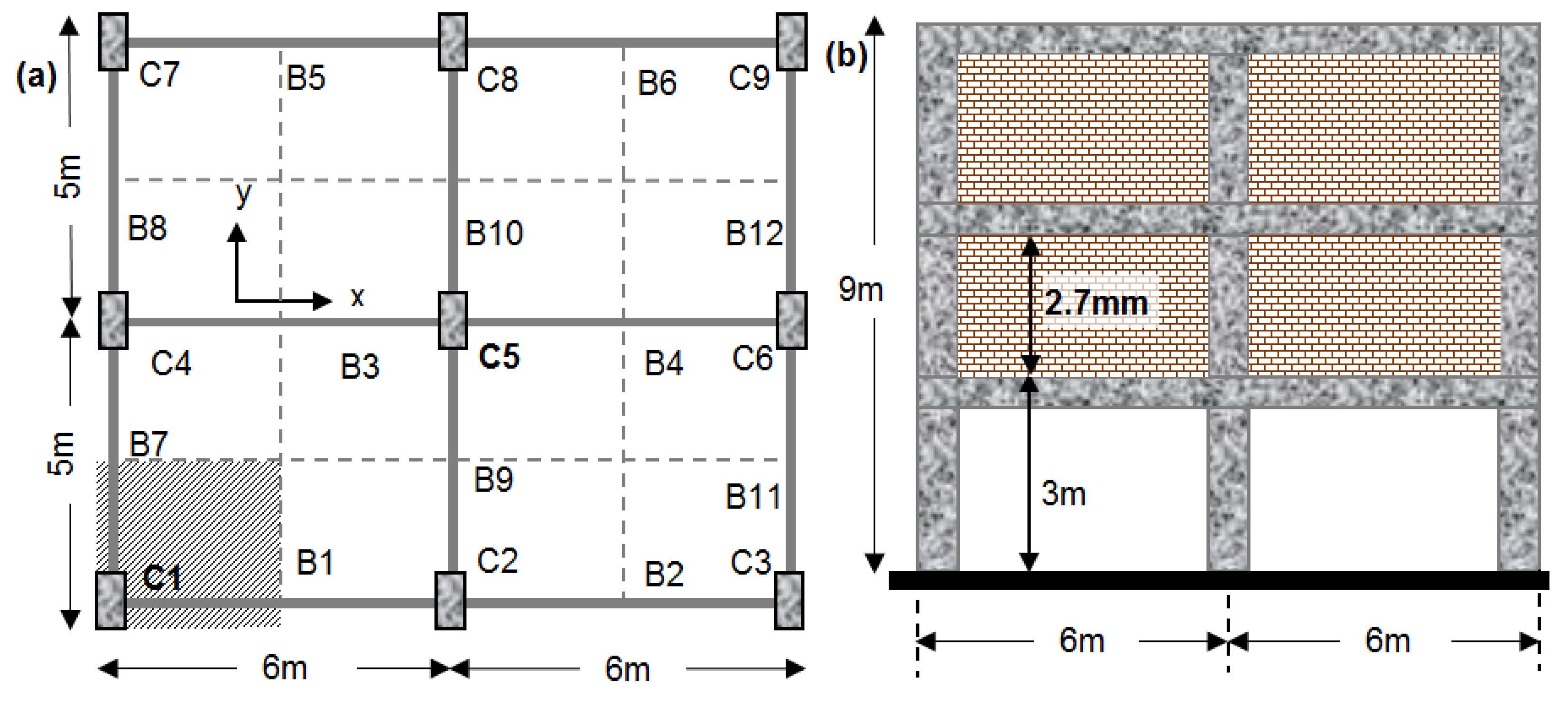
Figure 1. (a) Plan view of a typical storey and (b) elevation view of the building.
Applsci 12 12950 g001
Figure 2. (a) Column cross section detailing and splice arrangement at column base and (b) beam geometry and longitudinal reinforcement detailing.
Applsci 12 12950 g002
Figure 3. Estimation of compression zone depth at ultimate for symmetrically reinforced concrete cross section with variables being the axial load and the amount of reinforcement.
Applsci 12 12950 g003
Figure 4. (a) Flowchart on the decision of implementing local and/or global interventions. For shear deflection shape (b) Storey stiffness ratios k i   = K i / K 1 and (c) corresponding stiffness to mass ratio for the first storey, K 1 / m 1 , versus period (note to obtain required K 1 values multiply the ordinate by the mass m, in tons).
Applsci 12 12950 g004
Figure 5. (a) Stiffness distribution of the enhanced building and (b) its lateral displacement profile after performing Rayleigh iterative method. (c) Compressive strain ductility μεc versus stirrup spacing s/Db for StIV.
Applsci 12 12950 g005
Figure 6. (a) FRP jacketing in ground floor columns and beam. (b) Strengthening of corner joint B1-C1-B7.
Applsci 12 12950 g006
Table 1. Results from cross section analysis and rotation capacity.
Cross Section Analysis: ApproximationsChord Rotation from
Procedures (a–c)
Columnϕy =
sy/h (1/m)
My (kNm)K
(kNm−1)
ϕu (1/m) − ξ
from Figure 3
θy (%)(a): θu (%)
θ = θuy)
(b): θu (%)
θ = θuy)
(c): θu (%)
θ = θuy)
lpl = 160 mmlpl = 615 mm
1/3/7/9
vEd = 0.13
0.01438938100.05–0.240.640.8
(1.2)
1.6
(2.4)
2
(3.1)
1.7
(2.7)
2/4/6/8
vEd = 0.26
11549100.044–0.270.73
(1.1)
1.4
(2.2)
1.7
(2.6)
1.8
(2.8)
Publisher’s Note: MDPI stays neutral with regard to jurisdictional claims in published maps and institutional affiliations.