Abstract
Morphing airfoil is a promising technology for future aircraft to realize all-stage high performance. In the present paper, a conceptual aircraft with morphing airfoil is proposed and the aerodynamic characteristics of three types of morphing airfoils (variable-camber airfoil, variable-chord airfoil, and the combination of both morphing styles) are numerically investigated. The baseline airfoil is RAE 2822 supercritical airfoil; the Reynolds-averaged Navier–Stokes method is adopted for numerical simulation of flow around airfoils, and the accuracy of the numerical simulation method is validated by comparing with experimental data. It is found that the variable-camber and -chord airfoil can not only improve the high lift characteristics at take-off stage, but also increase the lift-to-drag ratio at transonic cruise and low-speed task stages during which the required lift is continuously decreasing due to the consumption of fuel. These findings imply that aircraft with proper morphing airfoil can achieve all-stage high aerodynamic performance.
1. Introduction
Performance is one of the most essential factors in the designing of aircraft. Traditional fixed-geometry aircraft cannot primely satisfy the aerodynamic performance requirements at different flight stages. As a new solution, morphing aircraft can change their aerodynamic configuration to ensure optimal performance under various environmental conditions and mission requirements [1,2,3,4,5,6,7,8,9,10]. Since the wing is the main component of the aircraft to provide lift, the primary research object of the current morphing aircraft technology is the morphing wing [11,12,13,14,15,16,17,18,19,20]. Specifically, the variable-camber airfoil technology that can be used on morphing wings has obvious advantages in improving the aerodynamic performance and enhancing the efficiency of the aircraft, which makes it attract extensive attention, and it has gradually become a research hotspot [21,22,23,24,25,26,27,28,29,30,31].
Extensive investigations have been conducted on aerodynamic aspects of variable-camber airfoil technology, with the main focus on aerodynamic design and benefits analysis of trailing-edge variable-camber airfoil. Two famous trailing-edge variable-camber designs are the Adaptive Compliant Trailing Edge (ACTE) [32,33,34] and the Variable Camber Continuous Trailing Edge Flap (VCCTEF) [35,36]. The ACTE technology, which is investigated by FlexSys and NASA, uses compliant structures to deform the trailing edge of the wing. This technology is relatively mature as a series of successful flights was tested on a testbed Gulfstream Ⅲ airplane [33]. The VCCTEF technology investigated by Boeing and NASA has completed aerodynamic analysis and optimization design of different VCCTEF configurations using two-dimensional airfoil and three-dimensional wing/body on a Generic Transport Model (GTM) under cruise condition [29,37,38]. Aiming at the aerodynamic aspects, Chen et al. [39], Majid and Jo [40], Lu et al. [41], and Tian et al. [30] utilize numerical simulation, experimental validation, and optimization design methods to conduct a systematic study on trailing-edge variable-camber airfoil at low-speed flight stage, and the critical design parameters and fine morphing strategy are identified. Besides, Niu et al. [26], Burdette and Martins [42], Lyu and Martins [43], Guo et al. [44,45,46], Shen et al. [47], Liang and Shan [48], He et al. [49], and Lei et al. [50] adopt drag reduction mechanism analysis, optimization design, and aerodynamic-performance benefits-quantification methods to perform series of trailing-edge variable-camber investigations under transonic cruise condition. Their research objects include airfoil, wing, and wing/body configuration, and the results show that variable-camber airfoil can achieve the largest drag reduction of 13.2% [44].
In addition to the above-mentioned aerodynamic research on trailing-edge variable-camber airfoils, some studies are also conducted on aerodynamic topics of the leading-edge variable-camber airfoil or both leading-edge and trailing-edge variable-camber airfoil. Magrini and Benini [51] indicate that the main benefit of the morphing leading edge is a substantial drag reduction. Kan et al. [28] studied the steady aerodynamic characteristics of the leading-edge variable-camber wing and unsteady aerodynamic characteristics under different leading-edge deflection frequencies. The design verification and optimization design research on aerodynamic aspects of Variable Camber Compliant Wing (VCCW) technology (both leading-edge and trailing-edge variable camber) undertaken by AFRL and others shows that VCCW is better than the flap-deflection method, and the benefits of increased lift under take-off stage and drag reduction under cruise condition are obvious [52,53]. Aiming at the aerodynamic topics of the both leading-edge and trailing-edge variable-camber technology, Kong et al. [54], Lu et al. [55], and Menshchikov and Somov [56] used numerical simulation or combined with a wind tunnel experiment to analyze the influence of both leading-edge and trailing-edge variable camber on the aerodynamic performance of airfoil at low-speed stage. Meanwhile, Zhang et al. [57] used high-fidelity aero-structural modeling to investigate the optimum deformations for a transonic airfoil, and the results reveal that morphing leading and trailing edges shows significant aerodynamic-performance improvement compared to morphing leading or trailing edges individually. Wang et al. [58] performed research on the influence of both leading-edge and trailing-edge variable camber on aerodynamic characteristics and optimization of drag reduction under transonic condition. These low-speed and transonic studies have obtained conclusions consistent with the VCCW research.
Based on the above aerodynamic research of variable-camber wings, it can be found that the aerodynamic benefits brought by variable-camber technology are not only reflected in the high lift performance at take-off stage, but also in the high lift–drag ratio performance under cruise stage; variable-camber technology is not only suitable for low-speed flight but also for transonic flight. Under this background, a scientific question raises about how morphing airfoil improves all-stage performance of an aircraft. Therefore, a conceptual aircraft with morphing airfoil is proposed in the present paper to investigate this scientific question. This kind of aircraft is designed to cruise at transonic speed and work at low speed. For example, it can respond rapidly from an airport hundreds of kilometers away to destinations for emergency rescue during the early stage of an epidemic or earthquake as well as for emergency detection of regional floods or forest fires, which denotes important value of application. The aerodynamic characteristics of three types of morphing airfoils (variable-camber airfoil, variable-chord airfoil, and the combination of both morphing styles) in the context of these conceptual aircraft missions is numerically investigated. The structure of the present paper is as follows: in Section 2, the conceptual morphing aircraft and the morphing airfoils are introduced; then, the method for numerical simulation is briefly described in Section 3; subsequently, Section 4 focuses on the results and discussions of aerodynamic characteristics; finally, conclusions are drawn in Section 5.
2. Conceptual Aircraft with Morphing Airfoil
Taking into consideration the fact that the required lift of an aircraft is continuously decreasing due to the fuel consumption during flight, morphing airfoil is utilized in this paper to achieve all-stage high performance of a conceptual aircraft. Supposing the take-off weight of this conceptual aircraft is W0. The aircraft enters the first high-altitude high-speed cruise stage (the Mach number of airfoil is 0.734, and the required lift range is 0.96W0~0.84W0) after the climbing stage; when it arrives at the destination, it lowers the altitude to enter the low-altitude low-speed mission stage (the Mach number of airfoil is 0.3, and the required lift range is 0.835~0.775W0); after this mission is completed, it climbs to high altitude and enters the second high-altitude high-speed cruise stage (the Mach number of airfoil is 0.734, the required lift range is 0.745~0.665W0); finally, it returns to the airport. The freestream conditions under these different flight stages are shown in Table 1. In order to realize high lift characteristics during the take-off stage and high lift-to-drag ratio characteristics during high-speed cruise and low-speed mission stage, three types of morphing airfoils are designed: variable-camber airfoil, variable-chord airfoil, and the combination of both morphing styles. Investigations on the aerodynamic characteristics of these morphing airfoils will be conducted to obtain the proper type of morphing airfoil for each flight stage.

Table 1.
Flight conditions under different flight states.
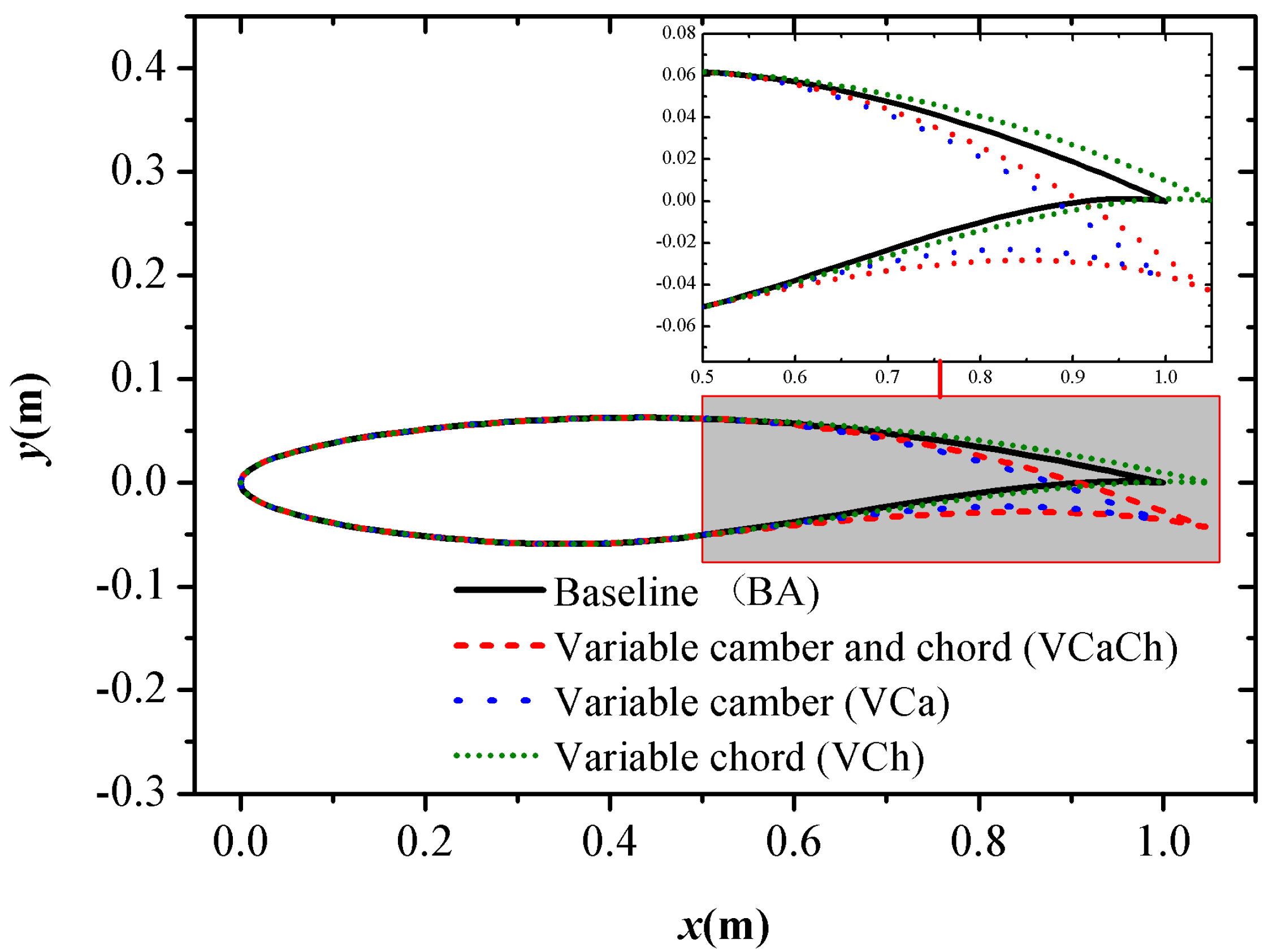
RAE 2822 supercritical airfoil is regarded as the baseline airfoil (identified as BA in the following). The baseline airfoil’s chord length is 1 m, and has the max thickness 12.11% at 37.9% chord. The simultaneous variable-camber and variable-chord airfoil (identified as VCaCh in the following) is obtained by translating the airfoil section after 70% chord length of the baseline airfoil by 5% chord length, and then deflecting the airfoil section from 90% chord length of the original airfoil to the trailing edge by a specified angle (upward deflection is negative and downward deflection is positive) when taking the thickness midpoint at 70% chord length of the baseline airfoil as the rotation axis. Finally, the airfoil section from 50% to 90% chord length is replaced by a smooth curve (in reality, this smooth curve is realized by flexible structure and flexible skin [8,59,60]; in a computational model, this smooth curve is realized by geometry software) so that a geometric model of variable camber and variable chord is obtained. The variable-camber airfoil (identified as VCa in the following) deflects the airfoil section from 90% chord length of the original airfoil to the trailing edge and the rotation axis is the same as VCaCh, then the airfoil section from 50% to 90% chord length is replaced by a smooth curve. The variable-chord airfoil (identified as VCh in the following) is obtained by translating the airfoil section after 70% chord length of the baseline airfoil by 5% chord length, then the airfoil section from 50% to 90% chord length is also replaced by a smooth curve. The above four airfoils are shown in Figure 1. In fact, there are mature implementation schemes to achieve the variable camber and variable chord mentioned above. For example, the ACTE technology uses compliant structures to make changes in wing trailing-edge shape with smoothly curved surfaces along the flow direction [32]. The variable chord can be realized by using the telescopic wing scheme, and the NextGen Company proposed the concept of sliding skin and conducted flight tests in which the chord length can be varied by up to 110% [61].
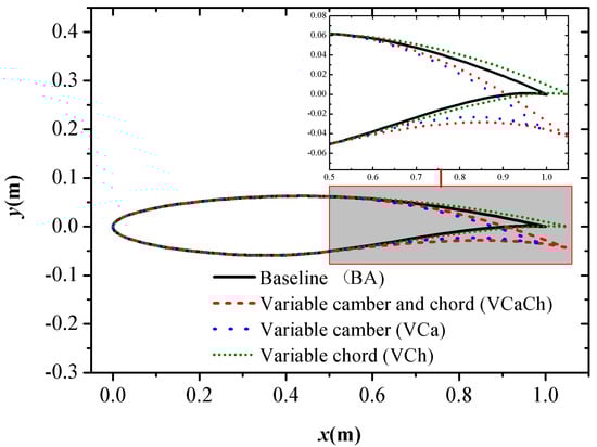
Figure 1.
RAE 2822 airfoil variable camber and chord-length diagram.
3. Numerical Simulation Method
3.1. Mathematical Model and Numerical Method
The Reynolds-averaged Navier–Stokes method is adopted for numerical simulation of flow around airfoils. The basic governing equations of compressible fluid flow under study are as follows:
where is Reynolds average velocity component with average sign omitted, is fluctuating velocity, is component of Kroneck tensor, is turbulent Prandtl number, is the sum of turbulent viscosity and molecular viscosity, which is called effective viscosity, and can be calculated by the Boussinesq hypothesis:
The turbulence model chooses the SST k-ω model [62], and its control equation is:
The formula of eddy viscosity coefficient in the above formula is:
where .
The simulations adopt an implicit algorithm, coupled solver, and choose the second-order upwind scheme as the discretization scheme. The boundary condition of the airfoil wall is a non-slip boundary condition, and the inlet and outlet of the far-field boundary, respectively, adopt pressure far-field and pressure outlet boundary conditions.
3.2. CFD Verification and Validation
As a classical two-dimensional transonic flow simulation validation case, the RAE 2822 airfoil case is widely selected as a numerical simulation method validation case [63,64]. In this case, the Mach number of Case 9 in an original wind tunnel experiment [65] is 0.73, the angle of attack is 3.19°, and the Reynolds number based on chord length (c = 0.61 m) is 6.5 × 10⁶. Here, the modified data [66] (Ma = 0.734, AOA = 2.79°, Re = 6.5 × 10⁶) are selected for verification and validation.
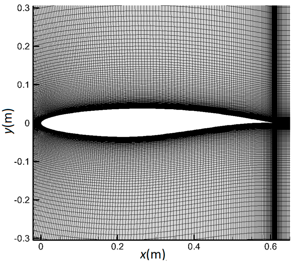
In this paper, the C-type structure grid is chosen, and the far-field boundary is about 20 times the chord length. Five sets of grids with different cell numbers (3.5 × 10⁴, 7.0 × 10⁴, 14.0 × 10⁴, 28.0 × 10⁴, 56.0 × 10⁴) are used for grid-independence research. Figure 2 shows the computational grid with a number of 14.0 × 10⁴ near the airfoil. The grids near airfoil wall, leading edge, and trailing edge are all encrypted. The first-layer grid near the wall grids is 3 × 10⁻⁶ m and the wall mesh has the y+ < 1 to resolve the boundary layer problem.
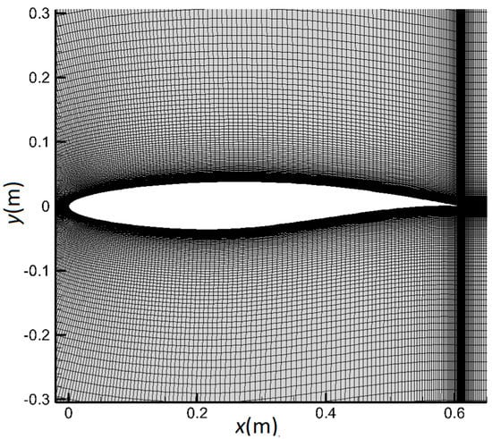
Figure 2.
Computational grid near the airfoil.
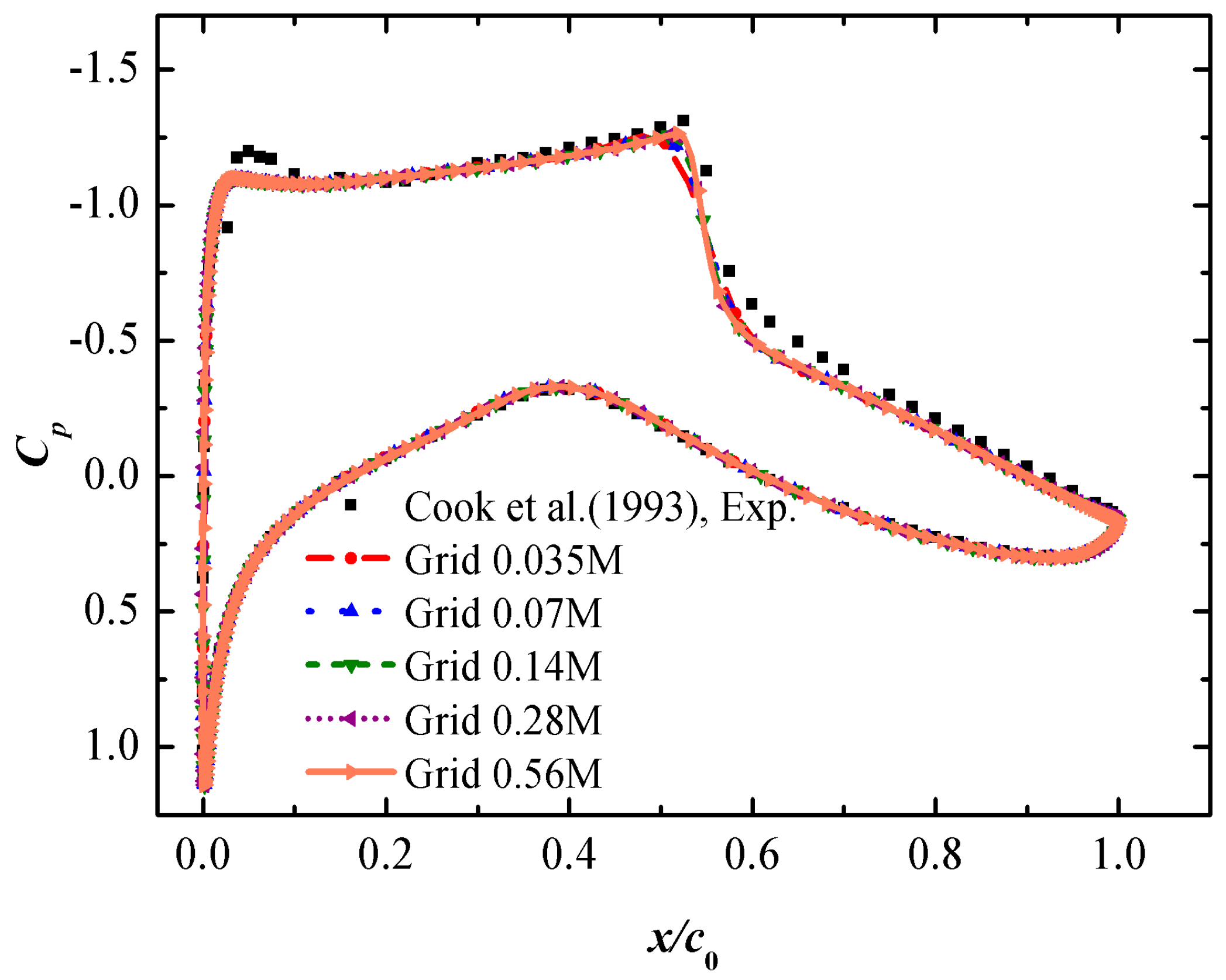
Table 2 shows the aerodynamic coefficient of different grids. The difference between the aerodynamic coefficient of the 14.0 × 10⁴ grid and the 28.0 × 10⁴ grid is less than 0.17%, which indicates that grid independence has been well achieved. It is verified that the numerical results obtained are independent of the density of the grid through the research of grid independence. Figure 3 shows the pressure coefficient Cp distributions on the airfoil surface resulting from numerical simulations and a wind tunnel experiment. The pressure coefficient distributions of the five grids are relatively close, but the shock waves captured by the 3.5 × 10⁴ and 7 × 10⁴ coarse grids are relatively inaccurate. Combining the results of Cp and aerodynamic coefficient, it is clear that the 14.0 × 10⁴, 28.0 × 10⁴, and 56.0 × 10⁴ grid cells could well reflect the flow state of the flow field, which confirms the accuracy of the numerical simulation method. On the premise of ensuring accuracy, the variable-camber and -chord-length airfoil will be investigated with 14.0 × 10⁴ grid cells to save computational resources.
Table 2.
Aerodynamic coefficient for different grids.
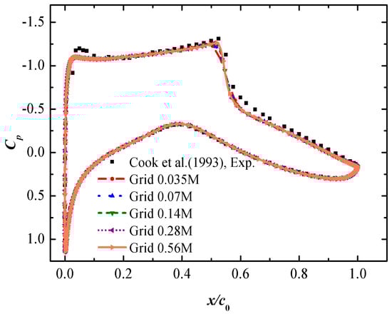
Figure 3.
Pressure coefficient distribution for different grids.
4. Results and Discussion
4.1. The Take-Off Stage at the Airport
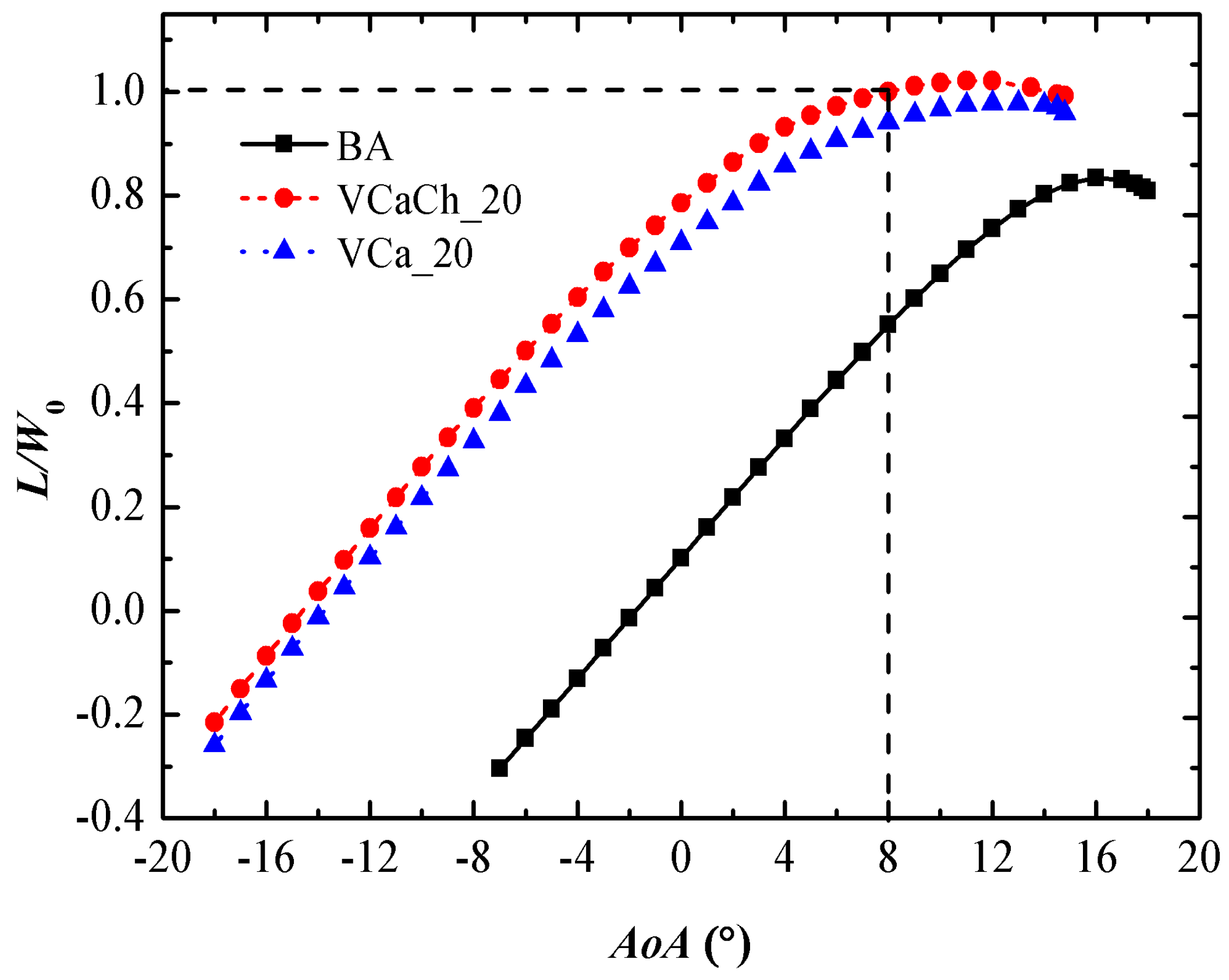
An aircraft has the largest weight at take-off state. Therefore, it is necessary to adopt high lift devices to increase lift. Trailing-edge deflection can significantly increase the lift of the airfoil. Therefore, the aerodynamic characteristics of simultaneous variable-camber and chord-length airfoil (VCaCh) and variable-camber airfoil (VCa) were compared (the deflection angle of the trailing edge of both airfoils is 20°). Figure 4 shows that stalling angle of the VCaCh airfoil is about 12°, supposing that the lift L when the attack angle AoA is 8° is equal to the required lift for takeoff, which is also equal to the take-off weight W0. The curves in Figure 4 indicate that the variable-camber airfoil significantly improves the maximum lift compared with the baseline airfoil (BA), and the lift improvement effect of VCaCh airfoil is better than that of VCa airfoil.
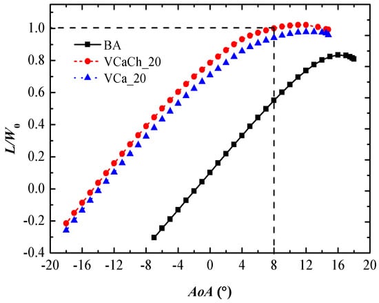
Figure 4.
Baseline and morphing-airfoil comparison: variation of L/W0 with AoA at Ma = 0.2.
4.2. The First High-Speed Cruise Stage of Flying to the Destination
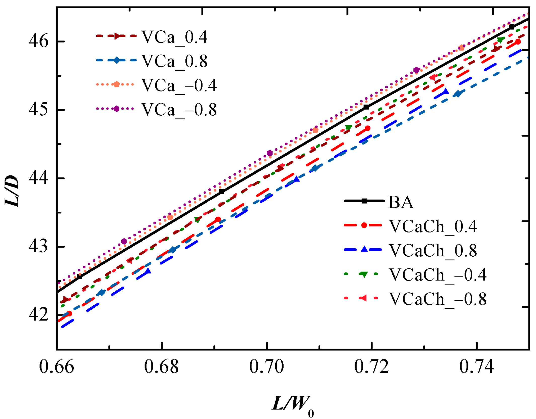
The lift–drag ratio is an essential aspect of morphing-benefit research as it can represent the flight aerodynamic efficiency and is a key parameter to be considered when an aircraft is in cruise state. Figure 5 shows the variation of L/D with L/W0 of VCaCh, VCa, and BA airfoil with different trailing-edge deflection angles at Ma = 0.734. The effects of the trailing-edge deflection angle of the morphing airfoil on the lift–drag ratio differ under different L/W0 ranges, as shown in Figure 5a. This study mainly compares the difference in lift–drag ratio under different L/W0 ranges throughout the designed flight stages. Therefore, Figure 5a was partially enlarged to obtain Figure 5b. The required lift range is 0.96~0.84W0 under the first high-speed cruise stage of flying to the destination. Figure 5b shows that the VCaCh morphing method can increase the lift–drag ratio whether with upward deflection or downward deflection, and the upward deflection effect is more significant. The increment of morphing airfoil that can improve the lift–drag ratio will raise with the increase in L/W0. VCaCh_0.4 airfoil is more excellent than VCaCh_0.8 airfoil in the range of L/W0 = 0.84~0.91, but it is the opposite in the range of L/W0 = 0.91~0.96. However, the VCa morphing method does not improve the lift–drag ratio under this stage, whether the trailing edge deflects upward or downward.
Figure 5.
Baseline and morphing-airfoil comparison: variation of L/D with L/W0 at Ma = 0.734. (a) L/W0 = 0.66~0.96; (b) the partially enlarged figure of (a): L/W0 = 0.84~0.96.
In Table 3, the lift–drag ratios of morphing airfoil and baseline airfoil are compared and the drag decomposition is conducted when the typical L/W0 = 0.95 is selected, so that the difference in lift–drag ratio of the morphing airfoil can be compared in more detail and the drag-reduction mechanism can be analyzed. The VCaCh_0.8 airfoil improves the lift–drag ratio by about 3.07% compared with BA airfoil, but VCa_0.8 airfoil fails to increase. From the results of drag decomposition, the friction drag Dfriction of VCaCh airfoil is greater than VCa airfoil, while the pressure drag Dpressure is significantly smaller than VCa when the deflection angle is the same. The pressure drag difference between the two morphing methods is larger than the friction drag difference, so the total drag Dtotal of VCaCh is smaller than that of VCa airfoil at this time, and the pressure drag is actually the reason that the total drag of VCaCh airfoil decreases compared with BA airfoil.
Table 3.
The drag decomposition and lift–drag ratio of morphing airfoil at Ma = 0.734, L/W0 = 0.95.
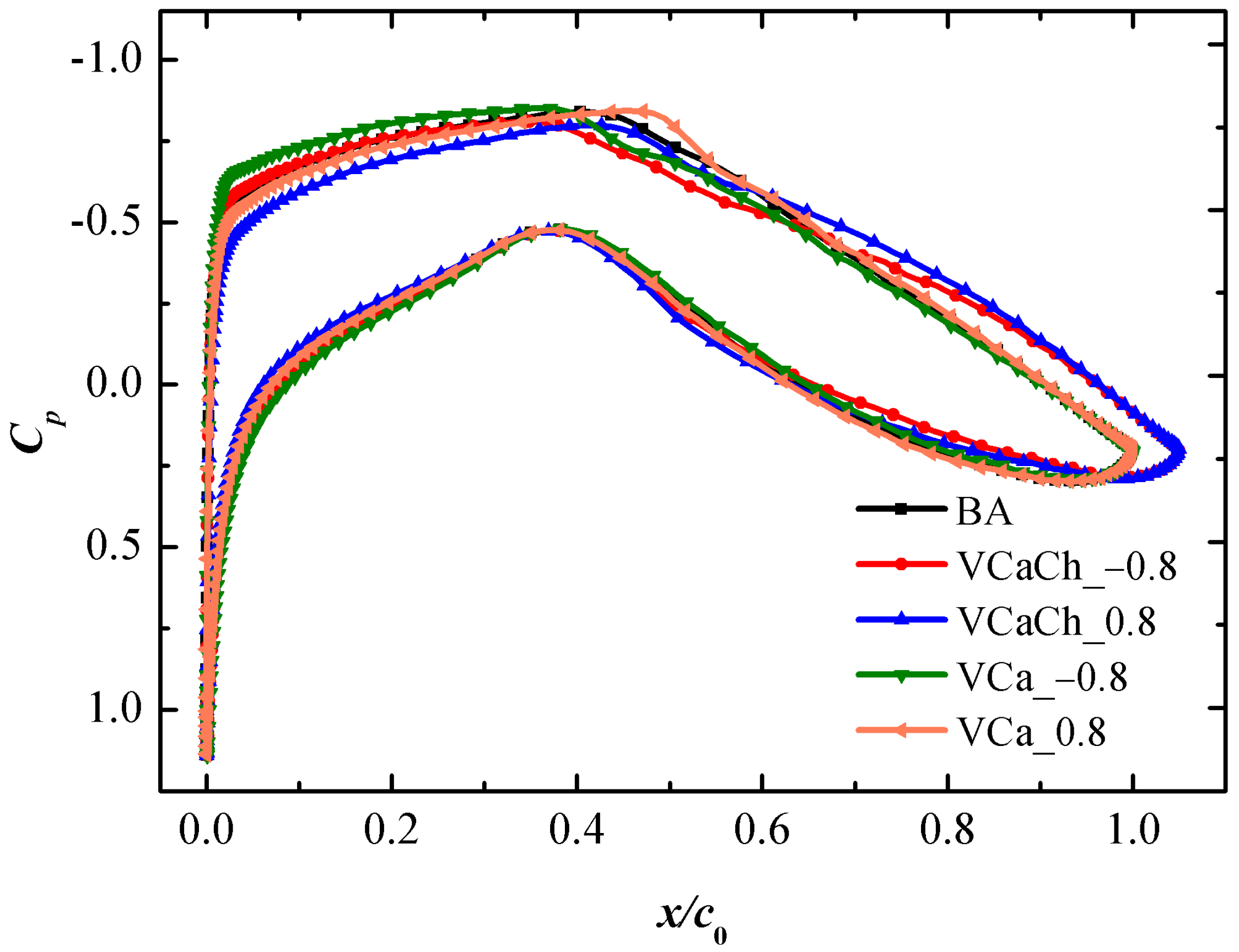
Pressure on the airfoil surface is the main source of aerodynamic force, and the variation of lift–drag characteristics is related to the change in pressure distribution to a great extent. In the transonic flow field around supercritical airfoil, the flow area above the upper surface of airfoil will form shock waves and cause shock-wave drag. Figure 6 shows the pressure coefficient distribution of morphing airfoil and BA airfoil when L/W0 = 0.95 and 0.86 during the first cruise stage. Firstly, the shock-wave position is analyzed. When the trailing edge deflects downward, the shock-wave position of VCa airfoil moves backward, while the VCaCh airfoil moves forward or changes unobviously. In terms of shock-wave intensity, both upward and downward deflections of VCaCh airfoil’s trailing edge can produce shock waves in different degrees. Instead, VCa airfoil upward deflection enhances shock waves or changes unobviously and downward deflection changes unobviously. Under the condition of L/W0 = 0.95, the BA airfoil has a strong shock wave, and the VCaCh_0.8 airfoil with the lowest total drag has the weakest shock wave. In the results of drag decomposition, the friction drag of VCaCh_0.8 is the largest, but the pressure and total drag are the smallest. This phenomenon can be explained in that, if the wave drag caused by a shock wave of VCaCh_0.8 airfoil is significantly reduced, then pressure drag reduces a lot, which indicates that the VCaCh morphing method mainly depends on wakening shock waves to improve aerodynamic characteristics under a transonic state.
Figure 6.
Pressure coefficient distributions of morphing airfoil at different L/W0. (a) L/W0 = 0.95; (b) L/W0 = 0.86.
In order to see the change of the shock-wave region in more detail, the algorithm proposed by Paparone et al. [67] was used to separate the shock-wave region, the formula is:
V is the incoming air flow velocity, and a is the local sound speed, and the region where Fwave ≥ 0.99 is supposed to be the shock-wave region. Shock-wave region diagrams of BA airfoil, VCaCh_0.8, and VCa_0.8 airfoil at L/W0 = 0.95 during the first cruise stage are shown in Figure 7. It can be seen that the shock wave’s position of VCaCh_0.8 airfoil is slightly different from that of BA airfoil, as the region is roughly in the range of x/c0 = 0.49~0.53. The maximum value of Fwave of VCaCh_0.8 airfoil, 1.15029, is also significantly lower than the 1.18437 of BA airfoil, which means the shock wave weakens greatly. On the other hand, the VCa_0.8 airfoil’s shock-wave position, which is in the range of x/c0 = 0.52~0.56, moves backward more obviously than that of BA airfoil, and the difference of the maximum value of Fwave between them is small.

Figure 7.
Shock-wave region for different morphing airfoils at Ma = 0.734, L/W0 = 0.95. (a) BA airfoil; (b) VCaCh_0.8 airfoil; (c) VCa_0.8 airfoil.
4.3. Low-Speed Flight Stage above the Destination
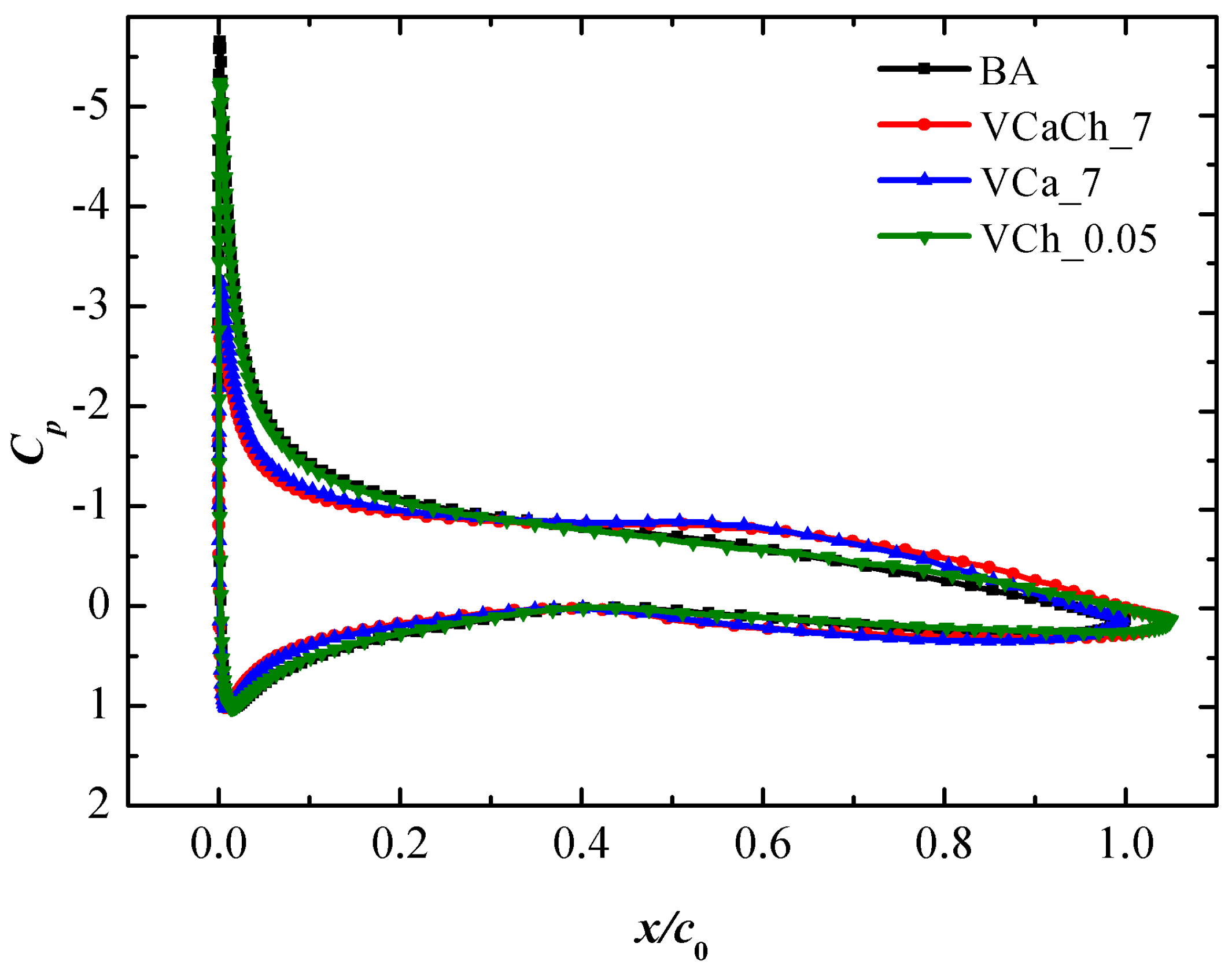
Figure 8 shows the variation of L/D with L/W0 of VCaCh and VCa airfoil with a trailing-edge deflection angle of 7°, VCh airfoil, and BA airfoil at Ma = 0.3. There are differences in lift–drag ratio among the three morphing methods under different L/W0 ranges, as shown in Figure 8. The results indicate that VCh morphing method can sightly improve lift–drag ratio compared with BA airfoil during the designed low-speed flight stage (L/W0 = 0.835~0.775), while VCaCh and VCa morphing methods have significant improvement. Besides, the VCaCh morphing method is better than VCa under the range of L/W0 = 0.805~0.835. In Table 4, the drag decomposition and lift–drag ratio of morphing airfoil are compared with that of BA airfoil at L/W0 = 0.83. Under this state, the lift–drag ratio of VCaCh_7 airfoil is increased by 4.82%, which is 0.22% higher than that of VCa_7 airfoil. From the analysis of drag decomposition, the friction drag of the three morphing airfoils is higher than that of the BA airfoil and the order is VCaCh > VCa > VCh > BA. This demonstrates that the simultaneous variable-camber and variable-chord method will increase friction drag compared to the variable-camber or variable-chord method. Besides, the pressure drags of the three methods are all reduced and the order is BA > VCh > VCa > VCaCh. Observing the pressure coefficient distributions in Figure 9, we find there is no shock wave at low speed, which means there is no shock-wave drag among pressure drag, and therefore all the pressure drag could be considered as form drag. Therefore, it can be concluded that both VCaCh and VCa airfoils obviously improve the lift–drag ratio by reducing the form drag during low-speed stage.
Figure 8.
Baseline and morphing-airfoil comparison: variation of L/D with L/W0 at Ma = 0.3.
Table 4.
The drag decomposition and lift–drag ratio of morphing airfoil at Ma = 0.3, L/W0 = 0.83.
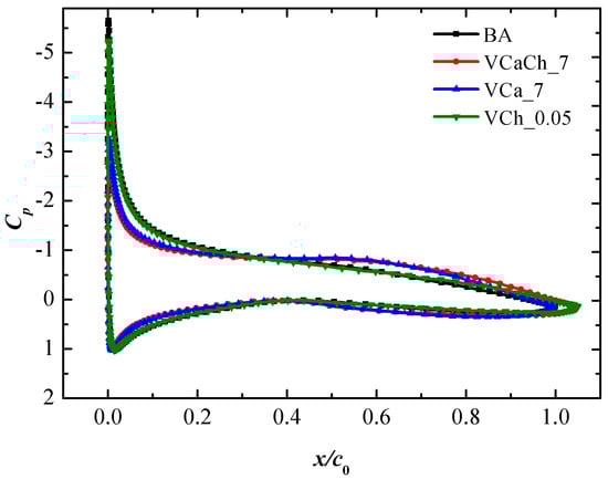
Figure 9.
Pressure coefficient distributions of morphing airfoil at Ma = 0.3, L/W0 = 0.83.
4.4. The Second High-Speed Cruise Stage of Flying Back to the Airport
During the second cruise stage in Figure 10, an aircraft needs smaller lift due to fuel consumption, ranging from 0.745W0 to 0.665 W0. Both VCaCh and VCa methods have little influence on lift–drag ratio at small L/W0. The lift–drag ratio can be improved by trailing-edge downward deflection with the VCa morphing method, but the improvement effect is small. The effect of the VCaCh morphing method is poor during this stage, and it fails to improve the lift–drag ratio. Table 5 shows that the improvement effect on lift–drag ratio of VCa_−0.8 airfoil with better aerodynamic efficiency is also very small, only 0.3%. Combined with the results of the first cruise stage, it can be concluded that with the decrease in required lift due to fuel consumption, the effect of variable camber on the lift–drag ratio is smaller under the transonic cruise stage. The results of drag decomposition show that trailing-edge downward deflection with the VCa morphing method can reduce total drag by reducing pressure drag at L/W0 = 0.7 during the second cruse stage. Although the pressure drag of VCaCh is smaller than VCa when the downward deflection angle is the same, the friction drag difference between them accounts for a larger proportion, resulting in smaller total drag of VCa. Therefore, the VCa morphing method is superior to VCaCh during this stage.
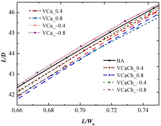
Figure 10.
Baseline and morphing-airfoil comparison: variation of L/D with L/W0 at Ma = 0.734.
Table 5.
The drag decomposition and lift–drag ratio of morphing airfoil at Ma = 0.734, L/W0 = 0.83.
Figure 11 shows the pressure distribution of BA airfoil under different L/W0 at Ma = 0.734. With the decrease in L/W0 (attack angle decreases), the leading-edge suction peak value decreases, the position of shock wave moves forward, and the shock wave is weakened. Furthermore, the shock wave of the BA airfoil is significantly weak when L/W0 = 0.7. According to the pressure coefficient distributions of morphing airfoil at L/W0 = 0.7 in Figure 12, the shock wave of VCaCh_−0.8 airfoil is weakened little compared with the BA airfoil, which has little influence on shock-wave drag. Therefore, the decrease in pressure drag of VCaCh_−0.8 airfoil is not enough to offset the increase in friction drag. The shock-wave strength of VCaCh_−0.8 airfoil is equivalent to that of the BA airfoil, which means its pressure drag decreases mainly because of the more obvious decrease in form drag.
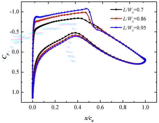
Figure 11.
Pressure coefficient distribution of the baseline airfoil under different L/W0 at Ma = 0.734.
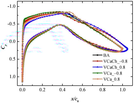
Figure 12.
Pressure coefficient distributions of morphing airfoil at Ma = 0.734, L/W0 = 0.7.
Combining with the pressure coefficient distribution during the above-two flight stages, it is found that the morphing airfoil has an influence on the leading-edge suction peak value. When the trailing edge deflects downward at the same L/W0, the leading-edge suction peak value increases compared with the BA airfoil, and the VCa airfoil increases more than VCaCh when the trailing edge deflects the same angle. Instead, compared with the BA airfoil, the leading-edge suction peak value decreases when the trailing edge deflects upward, and the decrease in VCaCh airfoil is greater than VCa when the trailing edge deflects the same angle. Then, the regularity can be explained as follows. When the trailing edge deflects upward, the attack angle of variable-camber airfoil required to reach the same L/W0 decreases due to the increase in camber, which shortens the acceleration region of the incoming flow at the head of the upper airfoil and reduces the peak value of negative pressure that is leading-edge suction peak value. This demonstrates that leading-edge suction peak value is related to the attack angle. At the same angle of downward deflection, the attack angle of VCaCh airfoil is smaller than that of VCa airfoil, which causes the leading-edge suction peak value decrement of VCaCh airfoil is larger. When the trailing edge deflects upward, the camber of the airfoil decreases along with the required attack angle increases, which causes the leading-edge suction peak value to increase. The VCa airfoil needs a larger attack angle, so the leading-edge suction peak value increment is larger.
5. Conclusions
Based on analyzing the influences of different airfoil morphing methods (simultaneous variable camber and chord (VCaCh), variable camber (VCa) alone, and variable chord (VCh) alone) on aerodynamic characteristics during four typical flight stages of a conceptual aircraft, the following conclusions can be drawn:
- (1)
- Both VCaCh and VCa morphing methods could improve the lift during the take-off stage. The benefits of VCaCh morphing method are more significant when the trailing edge deflects at the same angle. Therefore, if the take-off weight is large, the VCaCh morphing method is required.
- (2)
- During the first high-speed cruise stage of flying to the destination, the shock wave is quite strong at a larger L/W0. The VCaCh morphing method can significantly weaken the shock wave, reduce the shock-wave drag, and thus increase the lift-to-drag ratio.
- (3)
- During the low-speed flight stage above the destination, the pressure drag of VCaCh and VCa airfoils can be significantly reduced, which highly improves the lift–drag ratio.
- (4)
- The required lift force is small during the second high-speed cruise stage of flying back to the airport, and the shock wave is weak at a small L/W0. At this time, using the VCa morphing method of trailing-edge downward deflection could improve the lift–drag ratio, but the benefits are pretty small. This can be explained in that a variable camber improves the lift–drag ratio mainly through reducing the shock-wave drag, but the original shock-wave drag is actually small, so the influence of the variable camber on total drag is small.
- (5)
- During all stages of the flight, the adaptation of a VCaCh or VCa morphing method in a real-time manner can not only improve the high lift characteristics at take-off stage, but also increase the lift-to-drag ratio at transonic cruise and low-speed task stages during which the required lift is continuously decreasing due to the consumption of fuel, which implies that aircraft with proper morphing airfoil can achieve all-stage high aerodynamic performance.
Author Contributions
Conceptualization, Q.C., P.B.; methodology, writing—review, and supervision, Q.C.; investigation, Y.C., J.Z., Q.C., H.L.; computation, visualization, Y.C., J.Z.; formal analysis, Y.C., J.Z., Q.C.; writing—original draft, Y.C., J.Z., Q.C. All authors have read and agreed to the published version of the manuscript.
Funding
This work was supported by the National Natural Science Foundation of China (Grant No. 91741102), the Shenzhen Fundamental Research Program (Grant No. JCYJ20190807160413162), and the Fundamental Research Funds for the Central Universities (Grant No. 19lgzd15).
Institutional Review Board Statement
Not applicable.
Informed Consent Statement
Not applicable.
Acknowledgments
The authors would like to express their thanks for the support of the National Natural Science Foundation of China (Grant No. 91741102), the Shenzhen Fundamental Research Program (Grant No. JCYJ20190807160413162), and the Fundamental Research Funds for the Central Universities (Grant No. 19lgzd15).
Conflicts of Interest
The authors declare no conflict of interest.
References
- Ajanic, E.; Feroskhan, M.; Mintchev, S.; Noca, F.; Floreano, D. Bioinspired wing and tail morphing extends drone flight capabilities. Sci. Robot. 2020, 5, eabc2897. [Google Scholar] [CrossRef]
- Wu, K.; Zhang, P.; Wu, H. A new control design for a morphing UAV based on disturbance observer and command filtered backstepping techniques. Sci. China Technol. Sci. 2019, 62, 1845–1853. [Google Scholar] [CrossRef]
- Weisshaar, T.A. Morphing Aircraft Systems: Historical Perspectives and Future Challenges. J. Aircr. 2013, 50, 337–353. [Google Scholar] [CrossRef]
- Cui, E.J.; Bai, P.; Yang, J.M. The development path of smart morphing aircraft. Aeronaut. Manufact. Technol. 2007, 8, 38–41. [Google Scholar] [CrossRef]
- Bai, P.; Chen, Q.; Xu, G.; Liu, R.; Dong, E. Development status of key technologies and expectation about smart morphing aircraft. Acta Aerodyn. Sin. 2019, 37, 426–443. [Google Scholar]
- Chen, Q.; Yin, W.; Bai, P.; Leng, J.; Liu, Z. System design and characteristics analysis of a variable-sweep and variable-span wing-body. Acta Aeronaut. Astronaut. Sin. 2010, 31, 606–613. [Google Scholar]
- Xu, H.; Han, J.; Yun, H.; Chen, X. Calculation of the Hinge Moments of a Folding Wing Aircraft during the Flight-Folding Process. Int. J. Aerosp. 2019, 2019, 9362629. [Google Scholar] [CrossRef]
- Sun, J.; Guan, Q.; Liu, Y.; Leng, J. Morphing aircraft based on smart materials and structures: A state-of-the-art review. J. Intell. Mater. Syst. Struct. 2016, 27, 2289–2312. [Google Scholar] [CrossRef]
- Sun, X.; Gu, L.; Gong, C. Dynamics of a deflectable-nose missile. Sci. China Technol. Sci. 2012, 55, 3483–3494. [Google Scholar] [CrossRef]
- Yan, B.B.; Li, Y.; Dai, P.; Liu, S.X. Aerodynamic Analysis, Dynamic Modeling, and Control of a Morphing Aircraft. J. Aerosp. Eng. 2019, 32, 04019058. [Google Scholar] [CrossRef]
- Ameduri, S.; Concilio, A. Morphing wings review: Aims, challenges, and current open issues of a technology. Proc. Inst. Mech. Eng. Part C J. Mech. Eng. Sci. 2020, 0954406220944423. [Google Scholar] [CrossRef]
- Guo, S. Morphing Wing Technologies: Large Commercial Aircraft and Civil Helicopters. Aeronaut. J. 2020, 124, 2048–2053. [Google Scholar] [CrossRef]
- Liu, H.; Gao, X.; Wang, X. Parametric active aeroelastic control of a morphing wing using the receptance method. J. Fluids Struct. 2020, 98, 103098. [Google Scholar] [CrossRef]
- Fonzi, N.; Brunton, S.L.; Fasel, U. Data-driven nonlinear aeroelastic models of morphing wings for control. Proc. R. Soc. A Math. Phys. Eng. Sci. 2020, 476, 20200079. [Google Scholar] [CrossRef]
- Yang, W.; Xuan, J.; Song, B. Experimental Study on Flexible Deformation of a Flapping Wing with a Rectangular Planform. Int. J. Aerosp. Eng. 2020, 2020, 8857078. [Google Scholar] [CrossRef]
- Wang, C.; Zhang, R.; Zhou, C.; Sun, Z. Numerical Investigation on Flapping Aerodynamic Performance of Dragonfly Wings in Crosswind. Int. J. Aerosp. Eng. 2020, 2020, 7325154. [Google Scholar] [CrossRef] [Green Version]
- Xue, R.; Ye, Z.; Ye, K. Active aeroelastic wing application on a forward swept wing configuration. Eng. Appl. Comput. Fluid Mech. 2019, 13, 1063–1079. [Google Scholar] [CrossRef] [Green Version]
- De Gaspari, A.; Moens, F. Aerodynamic Shape Design and Validation of an Advanced High-Lift Device for a Regional Aircraft with Morphing Droop Nose. Int. J. Aerosp. Eng. 2019, 2019, 7982168. [Google Scholar] [CrossRef] [Green Version]
- Yin, D.; Zhang, Z. Design, fabrication and kinematics of a bio-inspired robotic bat wing. Sci. China-Technol. Sci. 2016, 59, 1921–1930. [Google Scholar] [CrossRef]
- Li, M.; Yuan, J.; Guan, D.; Chen, W. Application of piezoelectric fiber composite actuator to aircraft wing for aerodynamic performance improvement. Sci. China-Technol. Sci. 2011, 54, 395–402. [Google Scholar] [CrossRef]
- Lobo do Vale, J.; Raffaelli, J.; Suleman, A. Experimental Validation and Evaluation of a Coupled Twist-Camber Morphing Wing Concept. Appl. Sci. 2021, 11, 10631. [Google Scholar] [CrossRef]
- Pecora, R. Morphing wing flaps for large civil aircraft: Evolution of a smart technology across the Clean Sky program. Chin. J. Aeronaut. 2021, 34, 13–28. [Google Scholar] [CrossRef]
- Wang, B.W.; Yang, Y.; Qian, Z.S.; Wang, Z.G.; Lv, S.S. Review of technical development of variable camber wing. Acta Aeronaut. et Astronaut. Sin. 2020, 57, 603–614. [Google Scholar]
- Concilio, A.; Dimino, I.; Pecora, R. SARISTU: Adaptive Trailing Edge Device (ATED) design process review. Chin. J. Aeronaut. 2020, 34, 187–210. [Google Scholar] [CrossRef]
- You, H.; Kim, S.; Yun, G.J. Design Criteria for Variable Camber Compliant Wing Aircraft Morphing Wing Skin. AIAA J. 2020, 58, 867–878. [Google Scholar] [CrossRef]
- Niu, W.; Zhang, Y.; Chen, H.; Zhang, M. Numerical study of a supercritical airfoil/wing with variable-camber technology. Chin. J. Aeronaut. 2020, 33, 1850–1866. [Google Scholar] [CrossRef]
- Keidel, D.; Fasel, U.; Ermanni, P. Control Authority of a Camber Morphing Flying Wing. J. Aircr. 2020, 57, 603–614. [Google Scholar] [CrossRef]
- Kan, Z.; Li, D.; Shen, T.; Xiang, J.; Zhang, L. Aerodynamic characteristics of morphing wing with flexible leading-edge. Chin. J. Aeronaut. 2020, 33, 2610–2619. [Google Scholar] [CrossRef]
- Kaul, U.K.; Nguyen, N.T. Drag Characterization Study of Variable Camber Continuous Trailing Edge Flap. J. Fluids Eng. 2018, 140, 101108. [Google Scholar] [CrossRef]
- Tian, Y.; Wang, T.; Liu, P.; Feng, P. Aerodynamic/mechanism optimization of a variable camber Fowler flap for general aviation aircraft. Sci. China Technol. Sci. 2017, 60, 1144–1159. [Google Scholar] [CrossRef]
- Yin, W. Stiffness requirement of flexible skin for variable trailing-edge camber wing. Sci. China Technol. Sci. 2010, 53, 1077–1081. [Google Scholar] [CrossRef]
- Wakayama, S.; White, E.V. Evaluation of Adaptive Compliant Trailing Edge Technology. In Proceedings of the 33rd AIAA Applied Aerodynamics Conference, Dallas, TX, USA, 22–26 June 2015. [Google Scholar]
- Kota, S.; Flick, P.; Collier, F. Flight Testing of the FlexFloilTrade Adaptive Compliant Trailing Edge. In Proceedings of the 54th AIAA Aerospace Sciences Meeting, San Diego, CA, USA, 4–8 January 2016. [Google Scholar]
- Smith, M.S.; Bui, T.T.; Garcia, C.A.; Cumming, S.B. Longitudinal aerodynamic modeling of the adaptive compliant trailing edge flaps on a GIII airplane and comparisons to flight date. In Proceedings of the AIAA Atmospheric Flight Mechanics Conference, Washington, DC, USA, 13–17 June 2016. [Google Scholar]
- Nguyen, N. NASA Innovation Fund 2010 Project: Elastically Shaped Future Air Vehicle Concept; NASA Ames Research Center: Moffett Field, CA, USA, 2010. [Google Scholar]
- Nguyen, N.; Trinh, K.; Reynolds, K.; Kless, J.; Aftosmis, M.; Sr, J.U.; Ippolito, C. Elastically shaped wing optimization and aircraft concept for improved cruise efficiency. In Proceedings of the 51st AIAA Aerospace Sciences Meeting, Grapevine, TX, USA, 7–10 January 2013. [Google Scholar]
- Ting, E.; Chaparro, D.; Nhan, N.; Fujiwara, G.E.C. Optimization of Variable-Camber Continuous Trailing-Edge Flap Configuration for Drag Reduction. J. Aircr. 2018, 55, 2217–2239. [Google Scholar] [CrossRef]
- Liu, Y.; Bai, J.; Livne, E. Robust Optimization of Variable-Camber Continuous Trailing-Edge Flap Static Aeroelastic Action. AIAA J. 2017, 55, 1031–1043. [Google Scholar] [CrossRef]
- Chen, Q.; Bai, P.; Yin, W.; Leng, J.; Zhan, H.; Liu, Z. Analysis on the aerodynamic characteristics of variable camber airfoils with continuous smooth morphing trailing edge. Acta Aerodyn. Sin. 2010, 28, 46–53. [Google Scholar]
- Majid, T.; Jo, B.W. Comparative Aerodynamic Performance Analysis of Camber Morphing and Conventional Airfoils. Appl. Sci. 2021, 11, 10663. [Google Scholar] [CrossRef]
- Lu, W.S.; Tian, Y.; Liu, P.Q. Aerodynamic optimization and mechanism design of flexible variable camber trailing-edge flap. Chin. J. Aeronaut. 2017, 30, 988–1003. [Google Scholar] [CrossRef]
- Burdette, D.A.; Martins, J.R.R.A. Design of a transonic wing with an adaptive morphing trailing edge via aerostructural optimization. Aerosp. Sci. Technol. 2018, 81, 192–203. [Google Scholar] [CrossRef]
- Lyu, Z.; Martins, J.R.R.A. Aerodynamic Shape Optimization of an Adaptive Morphing Trailing-Edge Wing. J. Aircr. 2015, 52, 1951–1970. [Google Scholar] [CrossRef] [Green Version]
- Guo, T.; Bai, J.; Yang, T. Influence of continuous trailing-edge variable camber on aerodynamic characteristics of transonic airfoils. Acta Aeronaut. Astronaut. Sin. 2016, 37, 513–521. [Google Scholar]
- Guo, T.; Bai, J.; Yang, Y. Influence of continuous trailing-edge variable camber wing on aerodynamic characteristics of airliner. J. Beijing Univ. Aeronaut. Astronaut. 2017, 43, 1559–1566. [Google Scholar] [CrossRef]
- Guo, T.; Bai, J.; Li, L.; Chen, S. The morphing trailing-edge wing optimization design of the civil aircraft. Sci. Sin. Technol. 2018, 48, 55–66. [Google Scholar] [CrossRef]
- Shen, G.; Bai, J.; Liu, N.; Liu, R. Mechanical Simulation and Aerodynamic Analysis on a New Type of Wing Trailing Edge Variable Camber. J. Northwestern Polytech. Univ. 2016, 34, 578–586. [Google Scholar]
- Liang, Y.; Shan, X. Aerodynamic analysis and optimization design for variable camber airfoil of civil transport jet. Acta Aeronaut. Astronaut. Sin. 2016, 37, 790–798. [Google Scholar]
- He, M.; Yang, T.; Bai, J.Q.; Yang, Y. Drag reduction benefits of variable camber technology of airliner based on trailing-edge flap deflection. Acta Aeronaut. Astronaut. Sin. 2020, 41, 165–180. [Google Scholar]
- Lei, R.; Bai, J.; Xu, D.; Ma, S.; Hui, X.; Wang, H. Research on variable camber wing of civil aircraft considering buffeting characteristics. Sci. Sin. Technol. 2020, 50, 161–174. [Google Scholar]
- Magrini, A.; Benini, E. Aerodynamic Optimization of a Morphing Leading Edge Airfoil with a Constant Arc Length Parameterization. J. Aerosp. Eng. 2018, 31, 04017093. [Google Scholar] [CrossRef]
- Joo, J.J.; Marks, C.R.; Zientarski, L.; Culler, A. Variable camber compliant wing—Design. In Proceedings of the 23rd AIAA Adaptive Structures Conference, Kissimmee, FL, USA, 5–9 January 2015. [Google Scholar]
- Yeongmin, J.; Seongim, C.; Zientarski, L.A.; Joo, J.J. Aerodynamic characteristics and optimization techniques of a variable camber compliant win. In Proceedings of the 34th AIAA Applied Aerodynamics Conference, Washington, DC, USA, 13–17 June 2016. [Google Scholar]
- Kong, B.; Wang, F.; Zhou, T. The aerodynamic design of seamlessly camber-variable airfoil based on circulation control. Acta Aerodyn. Sin. 2013, 31, 583–586. [Google Scholar]
- Lu, W.S.; Tian, Y.; Liu, P.Q.; Wang, T.; Zhang, L. Aerodynamic performance of GAW-1 airfoil leading-edge and trailing-edge variable camber. Acta Aeronaut. Astronaut. Sin. 2016, 37, 437–450. [Google Scholar]
- Menshchikov, A.; Somov, A. Morphing wing with compliant aileron and slat for unmanned aerial vehicles. Phys. Fluids 2019, 31, 037105. [Google Scholar] [CrossRef]
- Zhang, Z.; De Graspari, A.; Ricci, S.; Song, C.; Yang, C. Gradient-Based Aerodynamic Optimization of an Airfoil with Morphing Leading and Trailing Edges. App. Sci. 2021, 11, 1929. [Google Scholar] [CrossRef]
- Wang, B.; Hao, X.; Guo, S.; Su, C. Cruise drag reduction of variable camber wing of wide-body civil transport. Acta Aerodyn. Sin. 2019, 37, 974–982. [Google Scholar]
- Campanile, L.; Sachau, D. The belt-rib concept: A structronic approach to variable camber. J. Intell. Mater. Syst. Struct. 2000, 11, 215–224. [Google Scholar] [CrossRef]
- Li, H.; Liu, L.; Xiao, T.; Ang, H. Design and simulative experiment of an innovative trailing edge morphing mechanism driven by artificial muscles embedded in skin. Smart Mater. Struct. 2016, 25, 095004. [Google Scholar] [CrossRef]
- Bowman, J.; Sanders, B.; Cannon, B.; Kudva, J.; Weisshaar, T. Development of Next Generation Morphing Aircraft Structures. AIAA 2007-1730, 2007. In Proceedings of the 48th AIAA/ASME/ASCE/AHS/ASC Structures, Structural Dynamics, Honolulu, HI, USA, 23–26 April 2007. [Google Scholar]
- Menter, F.R. Two-equation eddy-viscosity turbulence models for engineering applications. AIAA J. 1994, 32, 1598–1605. [Google Scholar] [CrossRef] [Green Version]
- Zhang, Y.F.; Zhang, X.L. Credibility analysis of RAE2822 airfoil transonic flow computation. Aeronaut. Comput. Tech. 2009, 039, 68–70. [Google Scholar] [CrossRef]
- Yu, T.; Wang, J.J.; Zhang, P.F. Numerical Simulation of Gurney Flap on RAE-2822 Supercritical Airfoil. J. Aircr. 2011, 48, 1565–1575. [Google Scholar] [CrossRef]
- Cook, P.H.; McDonald, M.A.; Firmin, M.C.P. Aerofoil RAE 2822—Pressure Distributions, and Boundary Layer and Wake Measurements; AGARD Report AR 138; Technical Editing and Reproduction Ltd.: London, Britain, 1979. [Google Scholar]
- Haase, W.; Brandsma, F.; Elsholz, E. EUROVAL—An European Initiative on Validation of CFD Codes; Notes on Numerical Fluid Mechanics, DLR; Springer: Berlin/Heidelberg, Germany, 1993. [Google Scholar]
- Paparone, L.; Tognaccini, R. Computational fluid dynamics-based drag prediction and decomposition. AIAA J. 2003, 41, 1647–1657. [Google Scholar] [CrossRef] [Green Version]


Publisher’s Note: MDPI stays neutral with regard to jurisdictional claims in published maps and institutional affiliations. |
© 2022 by the authors. Licensee MDPI, Basel, Switzerland. This article is an open access article distributed under the terms and conditions of the Creative Commons Attribution (CC BY) license (https://creativecommons.org/licenses/by/4.0/).