Abstract
The bimorph deformable mirror with a diameter of 320 mm, including 127 control electrodes, has been developed and tested. The flatness of the initial mirror surface of about 1 μm (P-V) was achieved by mechanically adjusting the mirror substrate fixed in the metal mount. To correct for the aberrations and improve the beam focusing in the petawatt Ti:Sa laser, the wide-aperture adaptive optical system with the deformable mirror and Shack–Hartmann wavefront sensor was developed. Correction of the wavefront aberrations in the 4.2 PW Ti:Sa laser using the adaptive system provided increases the intensity in the focusing plane to a value of 1.1 × 10²³ W/cm2
1. Introduction
At present, many modern laser facilities have already achieved a peak power of several PW [1,2,3], which creates the unique conditions for fundamental research on laser–matter interaction. The intensity of the focused radiation of this type of laser is mainly in the range of 1019–1021 W/cm2, which is sufficient for carrying out the relativistic optical experiments on the acceleration of the electrons and ions, generation of X-ray and gamma radiation, etc. [4]. However, to study the extreme phenomena in quantum electrodynamics, such as nonlinear Compton scattering, physical interaction of the light beams, and vacuum birefringence, the required intensity must be higher than 1022 W/cm2 [5]. Increasing the intensity to the specified levels in petawatt lasers is currently possible only with the use of adaptive optics [6,7,8].
The multi-petawatt Ti:Sa laser consists of a femtosecond oscillator with an amplifier, a grating pulse stretcher, an OPCPA preamplifier, power amplifier stages and a grating pulse compressor. According to this scheme, a Ti:Sa laser with a power of 4.2 PW (energy and pulse duration of 83 J and 20 fs, respectively), operating with a pulse repetition rate of 0.1 Hz, was built in CoReLS (Korea) [3]. Measurement of the wavefront (WF) distortion of PW radiation by a wavefront sensor (WFS) located after the pulse compressor showed the presence of the aberrations with an amplitude of about 3 µm (P-V) [9]. The main sources of WF distortions are the thermal deformations of the active elements of the amplifying stages due to the powerful optical pumping as well as aberrations of the wide-aperture optical elements located after the amplifiers are used for the beam expansion and direction, as well as pulse compression. In addition, the focusing parabolic mirror in the interaction chamber will also introduce significant distortions. To compensate for WF aberrations, the wide aperture adaptive optical system (AOS) was installed in the optical setup of the laser facility. The unique part of this system was the bimorph-type 320 mm deformable mirror (DM) that was specially designed for this laser in order to maximally increase the beam intensity on the target. This article describes the features and the benefits of the 320 mm bimorph deformable mirror application to achieve the intensity of more than 1023 W/cm2 of Ti:Sa laser [10].
2. Materials and Methods (Design of a 320 mm Bimorph Deformable Mirror)
Experiments in high-power laser systems have shown that the real WF aberrations are so-called large-scale [11,12], and, therefore, WF correctors, including the deformable mirrors, should be effective in compensating for such aberrations. In some contemporary wide-aperture lasers, adaptive optical systems include DMs based on piezoelectric actuators and mechanical step motors [13,14,15]. Since such mirrors have local response functions, surface deformation occurs locally, just in the area of each actuator, and thus a large number of actuators is required to compensate for large-scale aberrations. This, naturally, affects the complexity of the wavefront correctors, as well as the quality and reliability of the entire adaptive system. Moreover, the pattern of the actuators might print through the mirror substrate (so-called “print-through” effect) [13], which leads to the appearance of undesirable small-scale aberrations (almost like grating), diffraction scattering and additional maxima of intensity in the focal plane. In the future, ultra-high-power lasers should provide multipetawatt pulses with a repetition rate of 10 Hz (ELI HALPS project) [14] or even 100 Hz (GEKKO-EXA project) [15] to initiate laser confinement fusion. It should be noted that mechanical DMs are very slow (the time of one control cycle is more than 0.1 s), which does not allow using them to dynamically correct for the aberrations of each pulse with such a repetition rate.
Bimorph deformable mirrors differ from the other types of mirrors due to their possibility of precise correction for the large-scale aberrations using the rather small number of control electrodes [16]. Bimorph DMs of medium size (100–170 mm in diameter) installed in titanium-sapphire lasers with a peak power of 100–200 TW have already made it possible to achieve the intensities of 1019–1020 W/cm2 [17,18,19], which confirms the efficiency of this type of mirrors. This paper presents a wide-aperture bimorph deformable mirror for WF correction and improving the focusing quality of the petawatt power level laser beam. Since the size of DM in petawatt lasers must be large, the amplitude of the surface aberrations increases rapidly. Therefore, the DM design should include the possibility of preliminary adjustment of the surface shape.
A traditional bimorph DM consists of a firmly glued-together passive reflecting substrate and a thin piezoceramic plate with a grid of control electrodes [16,20,21]. The one-piece piezoceramic plate can be used for small-to-medium sized correctors. However, the mosaic of individual piezoplates should be arranged to cover the entire area of the substrate when constructing a large bimorph mirror (over 240 mm), as it is not possible to have a thin piezo ceramic disk with a diameter more than 240 mm. The disadvantage of such a mosaic configuration might be the fact that the mirror areas within each plate acts as an independent corrector. As a result, the mechanical stresses arise at the boundaries between the piezoelectric elements, and thus the “print through” is visualized on the mirror surface. However, the specific shape and the arrangement of the piezoceramic elements can significantly reduce the influence of this effect [22]. For wide-aperture DMs (300 mm and more), when the ratio of the substrate thickness to its diameter is about 1/50, the impact of the mirror’s own aberrations increases. In addition, when the thin substrate is fixed in the housing, the additional surface distortion appears in the area of the contact between the substrate and the mount parts (mirror housing). The value of the surface curvature also depends on the gravity and the changes in ambient temperature. The total surface distortions arising from the manufacturing errors, internal stresses in the dielectric layers of the coating, the effect of “printing” of the piezoelectric plates and fixing the substrate in the mount can significantly exceed the WF aberrations, for which DM is intended to compensate. In this case, most of the full voltage range should be spent to correct for initial distortions that makes DM useless in the adaptive systems.
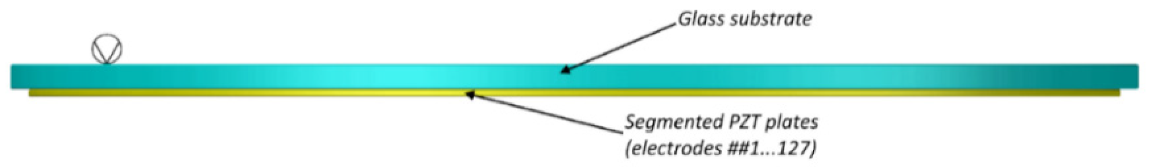
To correct for the beam aberrations in the CoReLS multipetawatt Ti:Sa laser [3], we developed the bimorph DM containing the glass substrate (BK7) with a diameter of 320 mm and thickness of 7 mm (Figure 1). A one-piece 240 mm piezoceramic disk was glued in the center of the substrate. The insulating paths were etched by the photolithography, and the grid of 91 electrodes was formed on the silver-covered disc surface. Nine piezoceramic plates in the form of the sectors were arranged around the big disk and filled the entire area of the substrate (Figure 2a). Each small plate contained four electrodes and, thus, the total number of the control electrodes was 127 (Figure 2b). Such a configuration of the arrangement of piezoceramic elements almost illuminated the “print through” effect of the glued piezoelectric plates.

Figure 1.
Design of the bimorph deformable mirror (##—numbers of the electrodes).
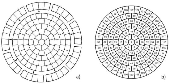
Figure 2.
Configuration of DM electrodes: (a) piezoceramic plates and their arrangement; (b) the map of the control electrodes.
The surface of the DM glass substrate was polished to a roughness of 2 nm (RMS). The flatness of the mirror after polishing was about 2 μm (P-V) including the overall concave curvature with a stroke of 1.8 μm. It should be noted that, at this stage, the curvature of the surface was not critical since it depends on the temperature. The significant change of the curvature as well as mirror profile is expected after the coating deposition. The multilayer dielectric coating provided a reflectivity of not less than 99.9% for a wavelength range from 740 to 860 nm, with a damage threshold of not less than 0.6 J/cm2 at a pulse duration of 20 fs.
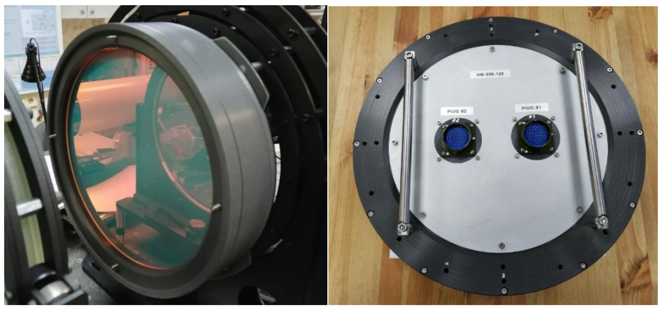
The coated mirror was installed in a metal mount, where it was fixed along the border through elastic spacers made of the porous silicone cord. Figure 3 shows the front and the back views of the mounted DM. Sixteen aligning screws located along the circle outside the mirror substrate were placed for adjusting the tension of the elastic spacers. Therefore, it was possible to push or pull the local sections of the mirror substrate to reduce the initial aberrations. Obviously, such a design allowed to compensate mechanically for astigmatism and a bit of coma aberrations that, as a rule, prevail in the initial surface distortions and require applying of the significant electrical voltage to correct for them. However, these screws cannot reduce mirror curvature and spherical aberration.
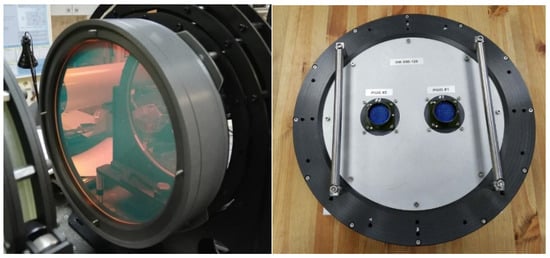
Figure 3.
Photos of the front and back views of DM.
3. Results
3.1. Investigations of the Deformable Mirror
DM study was carried out at the diagnostic setup based on Shack–Hartmann WFS [23]. The initial surface error excluding the overall surface curvature was about 14 μm after mirror assembly. To compensate for the curvature, the electric voltage of −34 V was applied to all 127 electrodes. After mechanical alignment with 16 screws, a flatness (P-V) equal to 1.03 μm (RMS = 0.17 μm) was achieved on a diameter of 300 mm. After correction in the closed-loop system with WFS feedback, the surface aberrations were decreased to P-V = 0.07 μm and RMS = 0.01 μm. Such a surface quality corresponds to a Strehl number of 0.99 (for the wavelength λ = 837 nm). The Fizeau interferograms of the DM surface before and after correction are shown in Figure 4a,b, where the flatness values (P-V and RMS) and residual aberrations in terms of orthogonal Zernike polynomials are presented on the right side of the pictures. The local deformation of the surface was about 1 μm (corresponding to the change in the wavefront of 2 μm) when the electric voltage of +150 V was applied to a single electrode. For the full range of the control voltages (from −300 to +600 V), deformation introduced by one electrode was expected to be at least 6 μm.
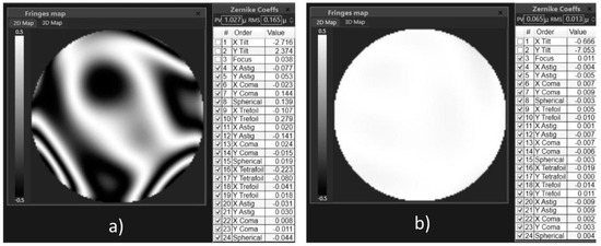
Figure 4.
The DM surface shape in terms of interferogram and expansion in Zernike polynomials (#—ordinal number of the Zernike polynomial): (a) the initial surface after manual correction without taking into account the curvature, P-V = 1.03 µm, RMS = 0.17 µm; (b) surface after aberrations correction in the closed-loop, P-V = 0.07 μm, RMS = 0.01 μm.
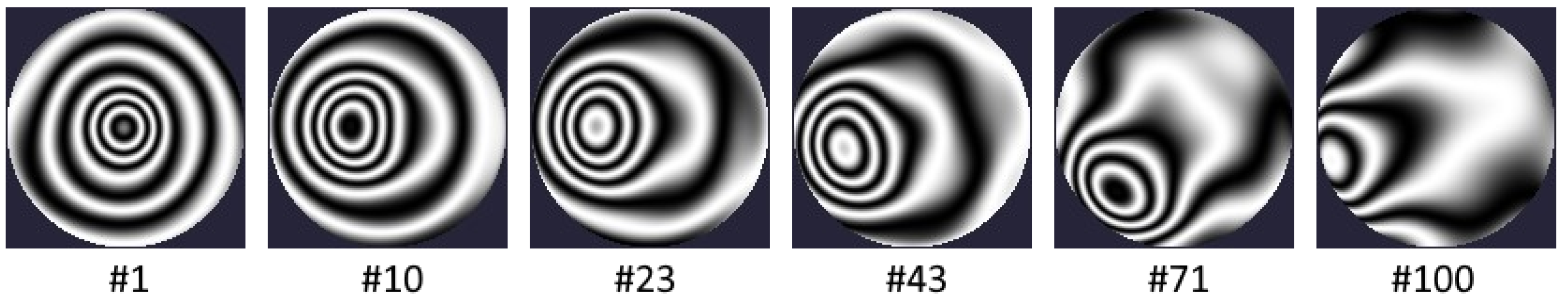
To measure the response functions, an electrical voltage of 100 V was applied sequentially to each electrode of the DM, and the change in the surface shape relative to its state in the absence of applied voltage was measured. In this case, the expansion coefficients were calculated in terms of the orthogonal Zernike polynomials, which can be used to construct a phase surface and represent it in the graphical form. The response functions of the bimorph DM are modal; when a voltage is applied to one of the electrodes, the surface deformation occurs not only in the area of the electrode location, but throughout the entire mirror aperture. Figure 5 shows examples of the response functions of some electrodes of a 320-mm bimorph DM presented in the form of the interferograms.
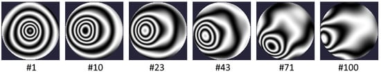
Figure 5.
Examples of the response functions of the electrodes under numbers ##1, 10, 23, 43, 71 and 100 in the form of the interferograms.
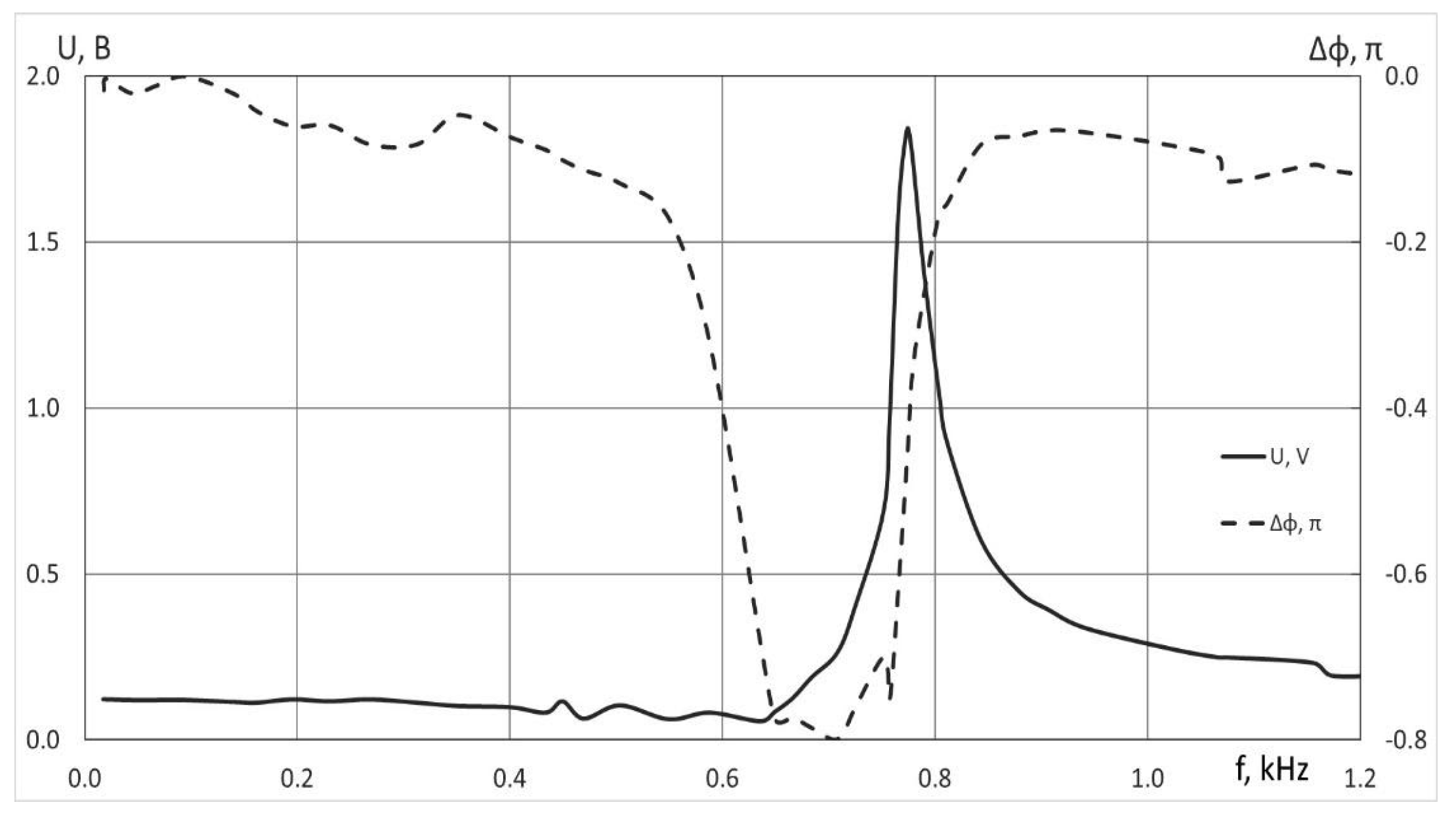
Investigations of the control frequency range of the corrector were carried out using a sound frequency generator and oscilloscope [24]. In this case, the induced piezoelectric signal was measured at one of the electrodes when a sine voltage was applied to the neighboring one. The phase shift between these signals was also studied. Figure 6 shows the change of the induced signal amplitude, as well as the phase shift versus the excitation frequency. The first resonance frequency when the response signal achieved the maximum amplitude and the phase shift was equal to π/2 was registered at 774 Hz. The presented graphs show the stability of the amplitude and phase for frequencies in the range from 0 to 400 Hz. Thus, this mirror provides the WF control at the frequencies up to 400 Hz and could even be used to correct for slowly changing phase fluctuations of the atmosphere in the pavilion where the whole laser is installed.
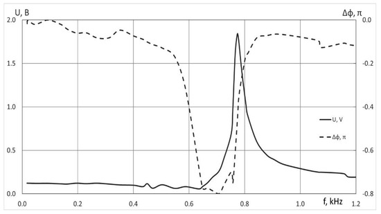
Figure 6.
Induced piezoelectric signal (solid line) and its phase shift (dashed line) vs. exitation frequency.
3.2. Wavefront Correction in a 4.2-Petawatt Ti: Sa Laser
The main parts of the CoReLS laser [3] and elements in the optical path from the end of power amplifiers to the target chamber are shown in Figure 7 [10]. The 127-channel bimorph mirror DM2 with a diameter of 320 mm was installed after the pulse compressor to compensate for additional WF aberrations arising in the wide-aperture optical elements and focusing optics in the compressor, the beam transport system and the interaction chamber. Wavefront correction was performed at a pulse energy of 89.7 J after booster amplifiers, while it decreased after the compressor to 55.6 J. The peak power in the target chumber was 2.7 PW. When measuring the wavefront and focal spot of the full power laser beam, the pulse energy was attenuated by the four high-quality (surface flatness below 20 nm RMS) partial reflection mirrors AM1-AM4 with 1%, 1%, 1% and 5% reflection coating. It was also assumed that the distortion of the wavefront from the thermal load in the pulse compressor was minimal due to the use of the fused quartz gratings. Thus, it would be expected that the divergence of the attenuated beam used for the measurement is not much different from the one at full energy.
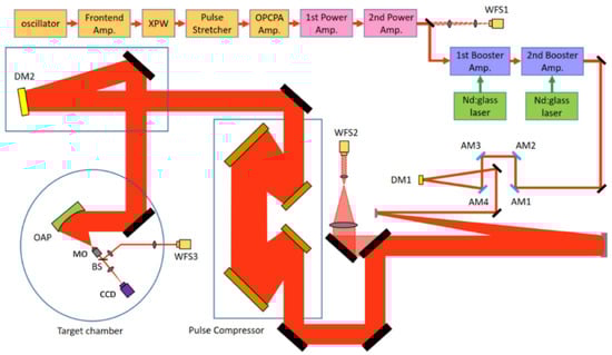
Figure 7.
Diagram of the petawatt laser setup with two adaptive systems: WFS1, WFS2, WFS3—wavefront sensors, DM1, DM2—deformable mirrors, AM1–AM4—attenuating mirrors, OAP—off-axis parabolic mirror, MO—micro objective, BS- beam splitter, CCD—video camera.
The phase conjugation algorithm [25] was used to control the DM2 based on the signals obtained from the Shack–Hartmann wavefront sensor WFS3. The 1-inch CMOS camera with a frame rate of up to 90 frames/s and the lenslet array with a size of 13.5 × 13.5 mm2 were used in WFS3. Thus, it contained more than 6500 microlenses with a focal length of 3.2 mm and size of 0.136 × 0.136 mm2. After focusing with an off-axis parabolic mirror (OAP), the beam was collimated using micro-objective MO. The part of the beam reflected from the beam splitter BS was directed to the sensor WFS3 (Figure 7). The video camera CCD recorded the intensity distribution in the focal plane of the OAP.
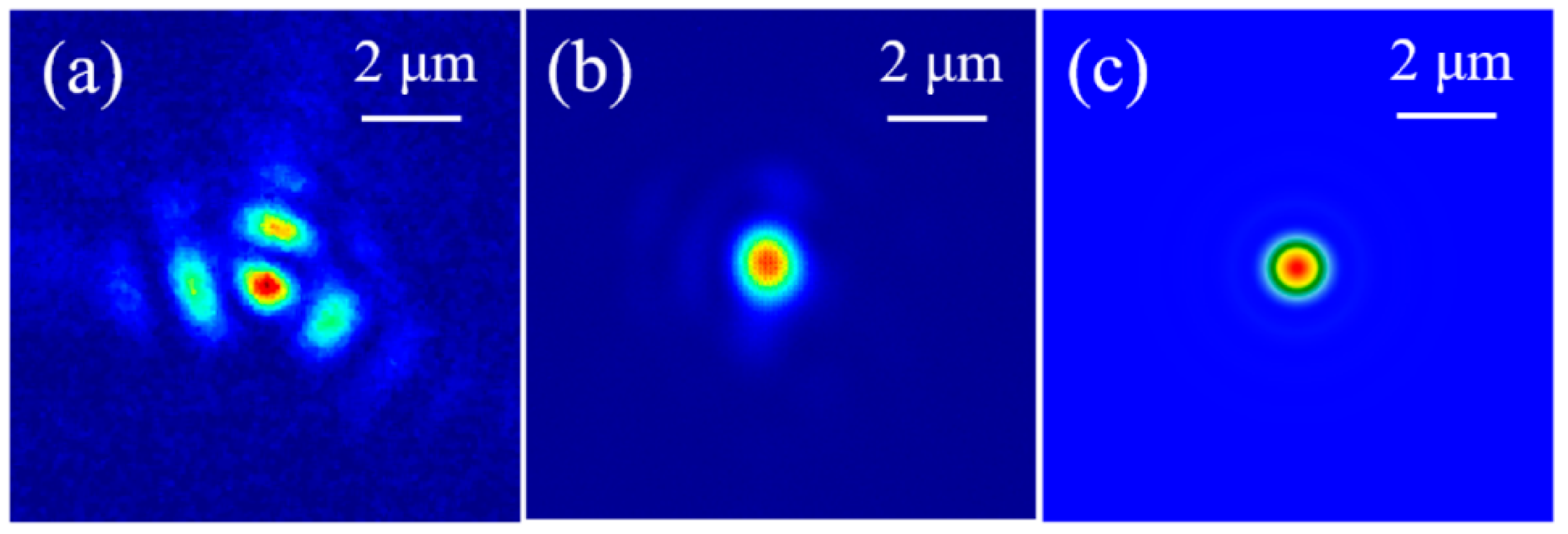
The wavefront correction reduced the initial value of the aberrations to 0.07 μm (RMS). After such a procedure in the focal plane of an f/1.1 parabolic mirror (focal length 300 mm), a significant increase in intensity was achieved. Figure 8 shows the images of the focal spots before and after correction. The corrected focal spot size was 1.1 μm (FWHM), and the calculated diffraction limit was 0.92 × 0.89 μm2. The peak intensity calculated for the focused 19.6 fs pulse (Figure 8b) at an energy of 55.6 J was equal to 1.1 × 10²³ W/cm2, which is a record among the values measured on high-power laser systems existing in the world [10].
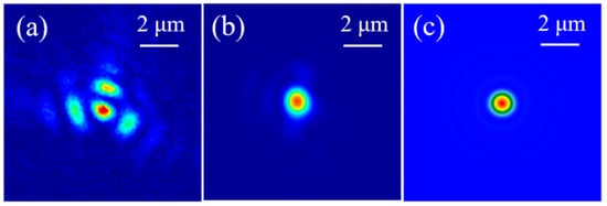
Figure 8.
Focal spot images: (a) before correction, (b) after WF correction, (c) diffraction quality for an f/1.1 parabolic mirror.
4. Conclusions
We have developed a wide-aperture bimorph deformable mirror with a diameter of 320 mm and a number of control electrodes of 127. The proposed shape and the arrangement of the piezoceramic plates reduced the “print-through” effect that usually appears on the reflective surface of the wide aperture mirrors. The design of the mirror allowed mechanically eliminating the initial aberrations of the mirror and obtaining a shape that differs from the flat one by 1 μm (P-V). The resonant frequency of the corrector was 774 Hz; the bandwidth of the mirror control was 400 Hz. The implementation of a wide-aperture adaptive optical system with a 320 mm bimorph deformable mirror in a 4.2 PW Ti:Sa laser increased the peak intensity at the interaction target to extreme values, allowing the study of new physical phenomena.
Author Contributions
Conceptualization, V.S. and A.K.; methodology, V.S.; software, I.G.; validation, A.A. and A.N.; formal analysis, J.S.; investigation, V.T.; resources, V.T.; data curation, A.A.; writing—original draft preparation, V.S.; writing—review and editing, A.K.; visualization, A.R.; supervision, A.K.; project administration, V.S.; funding acquisition, A.K. All authors have read and agreed to the published version of the manuscript.
Funding
This research was funded by grant No. 20-69-46064 of the Russian Science Foundation.
Institutional Review Board Statement
Not applicable.
Informed Consent Statement
Not applicable.
Data Availability Statement
The data presented in this article are available on request from the corresponding author. The stated results and data are confirmed in the published article [10] by Yoon, J.W. et al. Optica 2021, 8, 630–635.
Conflicts of Interest
The authors declare no conflict of interest.
References
- Danson, C.N.; Haefner, C.; Bromage, J.; Butcher, T.; Chanteloup, J.C.-F.; Chowdhury, E.A.; Galvanauskas, A.; Gizzi, L.A.; Hein, J.; Hillier, D.I.; et al. Petawatt and exawatt class lasers worldwide. High Power Laser Sci. Eng. 2019, 7, e54. [Google Scholar] [CrossRef]
- Chu, Y.; Gan, Z.; Liang, X.; Yu, L.; Lu, X.; Wang, C.; Wang, X.; Xu, L.; Lu, H.; Yin, D.; et al. High-energy large-aperture Ti:sapphire amplifier for 5 PW laser pulses. Opt. Lett. 2015, 40, 5011–5014. [Google Scholar] [CrossRef]
- Sung, J.H.; Lee, H.W.; Yoo, J.Y.; Yoon, J.W.; Lee, C.W.; Yang, J.M.; Son, Y.J.; Jang, Y.H.; Lee, S.K.; Nam, C.H. 4.2 PW, 20 fs Ti:sapphire laser at 0.1 Hz. Opt. Lett. 2017, 42, 2058–2061. [Google Scholar] [CrossRef] [PubMed]
- Kim, H.T.; Pathak, V.B.; Pae, K.H.; Lifschitz, A.; Sylla, F.; Shin, J.H.; Hojbota, C.; Lee, S.K.; Sung, J.H.; Lee, H.W.; et al. Stable multi-GeV electron accelerator driven by waveform-controlled PW laser pulses. Sci. Rep. 2017, 7, 10203. [Google Scholar] [CrossRef] [PubMed]
- Di Piazza, A.; Müller, C.; Hatsagortsyan, K.Z.; Keitel, C.H. Extremely high-intensity laser interactions with fundamental quantum systems. Rev. Mod. Phys. 2012, 84, 1177. [Google Scholar] [CrossRef] [Green Version]
- Wattellier, B.; Fuchs, J.; Zou, J.P.; Abdeli, K.; Haefner, C.; Pépin, H. High-Power Short-Pulse Laser Repetition Rate. Improvement by Adaptive Wave Front Correction. Rev. Sci. Instrum. 2004, 75, 5186–5192. [Google Scholar] [CrossRef] [Green Version]
- Soloviev, A.A.; Kotov, A.V.; Perevalov, S.E.; Esyunin, M.; Starodubtsev, M.; Alexandrov, A.; Galaktionov, I.; Samarkin, V.; Kudryashov, A.; Ginzburg, V.; et al. Adaptive system for wavefront correction of the PEARL laser facility. Quantum Electron. 2020, 50, 1115–1122. [Google Scholar] [CrossRef]
- Sueda, K.; Jitsuno, T.; Morio, N.; Matsuo, S.; Kawanaka, J.; Miyanaga, N. Waveform control and wavefront correction of a large-aperture high-energy glass laser system. Plasma Phys. Fusion Technol.–Laser Soc. Jpn. 2009, 37, 455–460. [Google Scholar]
- Yoon, J.W.; Jeon, C.; Shin, J.; Lee, S.K.; Lee, H.W.; Choi, I.W.; Kim, H.T.; Sung, J.H.; Nam, C.H. Achieving the laser intensity of 5.5 × 10²² W/cm2 with a wavefront-corrected multi-PW laser. Opt. Express 2019, 27, 20412–20420. [Google Scholar] [CrossRef]
- Yoon, J.W.; Kim, Y.G.; Choi, I.W.; Sung, J.H.; Lee, H.W.; Lee, S.K.; Nam, C.H. Realization of laser intensity over 1023 W/cm2. Optica 2021, 8, 630–635. [Google Scholar] [CrossRef]
- Spaeth, M.L.; Manes, K.R.; Widmayer, C.C.; Williams, W.H.; Whitman, P.K.; Henesian, M.A.; Stowers, I.F.; Honig, J. National Ignition Facility wavefront requirements and optical architecture. Opt. Eng. 2004, 43, 2854–2865. [Google Scholar] [CrossRef]
- Aleksandrov, A.G.; Zavalova, V.E.; Kudryashov, A.V.; Rukosuev, A.; Sheldakova, J.; Samarkin, V.V.; Romanov, P.N. Shack-Hartmann wavefront sensor to measure high power lasers. Quantum Electron. 2010, 40, 321. [Google Scholar] [CrossRef]
- Grosset-Grange, C.; Barnier, J.-N.; Chappuis, C.; Cortey, H. Design principle and first results on the LMJ deformable mirror prototype. Proc. SPIE 2007, 6584, 658403. [Google Scholar]
- Lefaudeux, N.; Levecq, X.; Dovillaire, G.; Ballesta, J.; Lavergne, E.; Sauvageot, P.; Escolano, L. Development of a new technology of deformable mirror for ultra intense laser applications. Nucl. Instrum. Methods Phys. Sect. A Accel. Spectrometers Detect. Assoc. Equip. 2011, 653, 164–167. [Google Scholar] [CrossRef]
- Bokalo, S.Y.; Garanin, S.G.; Grigorovich, S.V.; Zhupanov, V.G.; Koltygin, M.O.; Kulikov, S.M.; Lyakhov, D.M.; Manachinckii, A.N.; Mizin, P.P.; Ogorodnikov, A.V.; et al. Deformable mirror based on piezoelectric actuators for the adaptive system of the Iskra-6 facility. Quantum Electron. 2007, 37, 691–696. [Google Scholar] [CrossRef]
- Toporovskiy, V.V.; Kudryashov, A.V.; Samarkin, V.V.; Sheldakova, J.; Rukosuev, A.; Skvortsov, A.; Pshonkin, D. Bimorph deformable mirror with a high density of electrodes to correct for atmospheric distortions. Appl. Opt. 2019, 58, 6019–6026. [Google Scholar] [CrossRef]
- Fourmaux, S.; Payeur, S.; Alexandrov, A.G.; Serbanescu, C.; Martin, F.; Ozaki, T.; Kudryashov, A.; Kieffer, J.C. Laser beam wavefront correction for ultra high intensities with 100 TW laser system at the Advanced Laser Light Source. Opt. Express 2008, 16, 11987. [Google Scholar] [CrossRef]
- Aleksandrov, A.G.; Zavalova, V.E.; Kudryashov, A.V.; Rukosuev, A.; Samarkin, V.V. Adaptive Correction of a High-Power Titanium-Sapphire Laser Radiation. J. Appl. Spectrosc. 2005, 72, 744–750. [Google Scholar] [CrossRef]
- Akahane, Y.; Ma, J.; Fukuda, Y.; Aoyoma, M.; Kiriyama, H.; Sheldakova, J.V.; Kudryashov, A.V.; Yamakawa, K. Characterization of wave-front corrected 100 TW, 10 Hz laser pulses with peak intensities greater than 1020 W/cm2. Rev. Sci. Instrum. 2006, 77, 023102. [Google Scholar] [CrossRef]
- Kokorowski, S.J. Analysis of adaptive optical elements made from piezolectric bimorphs. J. Opt. Soc. Am. 1979, 69, 181–187. [Google Scholar] [CrossRef]
- Steinhaus, E.; Lipson, S.G. Bimorph piezoelectric flexible mirror. J. Opt. Soc. Am. 1979, 69, 478–481. [Google Scholar] [CrossRef]
- Samarkin, V.V.; Aleksandrov, A.G.; Jitsuno, T.; Romanov, P.N.; Rukosuev, A.L.; Kudryashov, A. Study of a wide-aperture combined deformable mirror for high-power pulsed phosphate glass lasers. Quantum Electron. 2015, 45, 1086–1087. [Google Scholar] [CrossRef]
- Nikitin, A.N.; Sheldakova, J.V.; Kudryashov, A.V.; Borsoni, G.; Denisov, D.; Karasik, V.; Sakharov, A. A device based on the Shack-Hartmann wave front sensor for testing wide aperture optics. Proc. SPIE 2016, 9754, 97540K. [Google Scholar]
- Toporovsky, V.V.; Samarkin, V.V.; Sheldakova, J.V.; Rukosuev, A.; Kudryashov, A. Water-cooled stacked-actuator flexible mirror for high-power laser beam correction. Opt. Laser Technol. 2021, 144, 107427. [Google Scholar] [CrossRef]
- Shanin, O.I. Adaptive Optical Systems in High Power Pulsed Laser Facilities; Technosphera: Moscow, Russia, 2012; 200p. [Google Scholar]


Publisher’s Note: MDPI stays neutral with regard to jurisdictional claims in published maps and institutional affiliations. |
© 2022 by the authors. Licensee MDPI, Basel, Switzerland. This article is an open access article distributed under the terms and conditions of the Creative Commons Attribution (CC BY) license (https://creativecommons.org/licenses/by/4.0/).