Abstract
Wind power is one of the best-known renewable energy sources, and it is mainly generated by wind turbines. With the recent development of large-scale offshore wind turbine technology and the improvements in capacity factor, the demand for offshore wind power is rapidly increasing for energy system applications worldwide. Such offshore wind turbine structures require structural capacity to withstand loads from offshore environments for a predetermined period of time. Generally, the load of the upper turbine system is transmitted through the grouted connection to the substructure. However, there are many cases of grout failure of the grouted connection between the tubular steels. This paper deals with the analysis of monopile grouted connections to which elastomeric bearings are applied. The grouted connection for the ultimate load of a 3.6 MW offshore wind turbine was analyzed using the three-dimensional finite element method. Furthermore, the changes in the contact pressure and shear stress were analyzed due to the installation of elastomeric bearings around the shear keys. As a result, when the elastomeric bearing was installed, the contact pressure for all grout contact areas increased about 2.5-fold. Specifically, the contact pressure with the shear key was 1.9-fold lower when natural rubber was used as the rubber plate material instead of chloroprene rubber. In addition, the maximum shear stress values of grout filler when installing the elastomeric bearings were 5.78 MPa for chloroprene rubber material and 4.90 MPa for natural rubber material, which were reduced by about 77–81% compared to the value of 25.95 MPa when only shear key was used.
1. Introduction
Offshore wind is a renewable energy technology with an important role in current and future energy systems [1,2,3]. At present, offshore wind turbines involve several types of substructures, such as monopiles, gravity-based structures, jackets, tripods, and floating supports [4,5]. Among them, monopiles are the most suitable type for supporting offshore wind turbines due to their advantages such as simple design, mass fabrication, and an installation approach based on conventional impact driving, relatively low risk, and robustness for most soil conditions. The offshore wind monopile substructure consists of a monopile (MP) and transition piece (TP), and the turbine system refers to the blade, nacelle, hub, and tower. The offshore wind foundation needs to be designed to be durable against various environmental loads for wind turbines to be able to execute the scheduled commercial operation. The grouted connection (GC) serves as the core structure to transfer the load from the turbine system to the foundation. Monopile grouting is a method wherein an MP is inserted into the seabed, the TP is mounted on the outside of the MP, and the two tubular steel members are integrated [6]. In general, a GC consists of components such as one grout annulus and two steel tubes with different dimensions [7]. Moreover, shear keys are generally added to the steel tube surfaces while making contact with the grout material in order to improve the interface shear capacity. As reviewed by Paul et al. [8], shear keys can be used to maximize the grout adhesion between two tubular steel pipe members at the GC. The shear keys are welded to the two tubular walls so that they are in contact with the grout, in which case the shear keys of the inner tube and the outer tube must be arranged to offset each other to form a grout strut. The shear keys can also be divided into horizontal and vertical shear keys, and the GC can be divided into two types, tubular and conical, where, in the conical type, the shear key would not be used. In the case of the horizontal shear key, it resists an axial load, whereas, in the case of the vertical shear key, it resists the torque of the turbine system. In general, GCs have been designed in accordance with the international design standards (i.e., DNVGL-ST-0126 [9] and DIN EN ISO 19902 [10]); however, GC failure has been reported under ultimate load and fatigue load such as (i) the occurrence of contact destruction between tubular steel pipes and grout material due to the generation of an ultimate or cyclic load that exceeds the lateral stiffness of the friction contact, and (ii) the occurrence of material failure along the grout strut or around the shear keys by shear stresses that exceed the shear capacity of the grout [3]. Therefore, to overcome these problems, the design stage of GCs for monopile offshore structures should be specified in the design of the grout thickness, number of shear keys, shear key size, vertical distance of adjacent shear keys, and grout compressive and tensile strength to prevent material and contact failure of the grout against limit states such as the ultimate limit state (ULS) and fatigue limit state (FLS).
This paper deals with the three-dimensional finite element (FE) analysis of a monopile GC with elastomeric bearings applied. The introduction of a shear key improves the GC structure response and capacity, but it limits the fatigue strength through stress concentration; hence, it should be addressed through a detailed refined local analysis. Elastomeric bearings are laminated rubber bearings widely used to reduce the response of structures due to their excellent deformability, stable mechanical properties, and low manufacturing cost [11]. If such an elastomeric bearing is installed around the shear keys of the GC, it is expected that the repeated or extreme shear force concentrated on the shear key will be dispersed, thus preventing the failure of the grout material or contact. However, despite these advantages, there has been no research investigating the installation of elastomeric bearings on the shear keys of offshore wind GC, thus motivating this study.
The elastomeric bearing, which comprises bearings made by intersecting reinforcing steel plates with elastomers of rubber material, was modeled to surround the shear key, and it was devised on the assumption that it would be possible to prevent grout failure due to the stress concentration through the elastomeric bearings under the extreme loads.
The ultimate load of a 3.6 MW class turbine was applied. In general, the load received by the pile in supporting an offshore wind turbine includes an axial load due to the weight of the turbine system and a bending moment due to an environmental load, and these two types of loads have been studied separately [12,13]. However, according to DNVGL-ST-0126, since the structural response of the grout shear key to two types of loads occurs in a complex way, it is practical to apply them simultaneously for the analysis of the GC. Although the combined action of these two types of loads has been continuously studied [14,15,16], it is a relatively realistic approach because GCs are the main subject of analysis. This load causes inclination of the pile head, which may change the direction of the load applied to the GC. According to DNVGL-RP-0419, the sub-modeling method can be applied when analyzing the GC; however, since it tends to ignore the change in the load direction due to the inclination of the pile, in this paper, the full model was analyzed.
The changes in contact pressure and shear stress due to the installation of the elastomeric bearings around the shear keys were analyzed. The guidelines for GC during FE analysis are detailed in Section 2.1. ANSYS 2021R1 was used as the FE analysis software. In Section 2.1, some of the design criteria for the monopile GC are presented, along with an identification of what should be paid attention to when designing GC. In Section 2.2, the site of the research model and its ultimate load are explained, and, in Section 3, the FE model is introduced in detail. Section 4 deals with the comparison of contact pressure and shear stress of the grout obtained through FE analysis.
2. Methodology and Materials
2.1. Design Standard of Monopile Grouted Connection
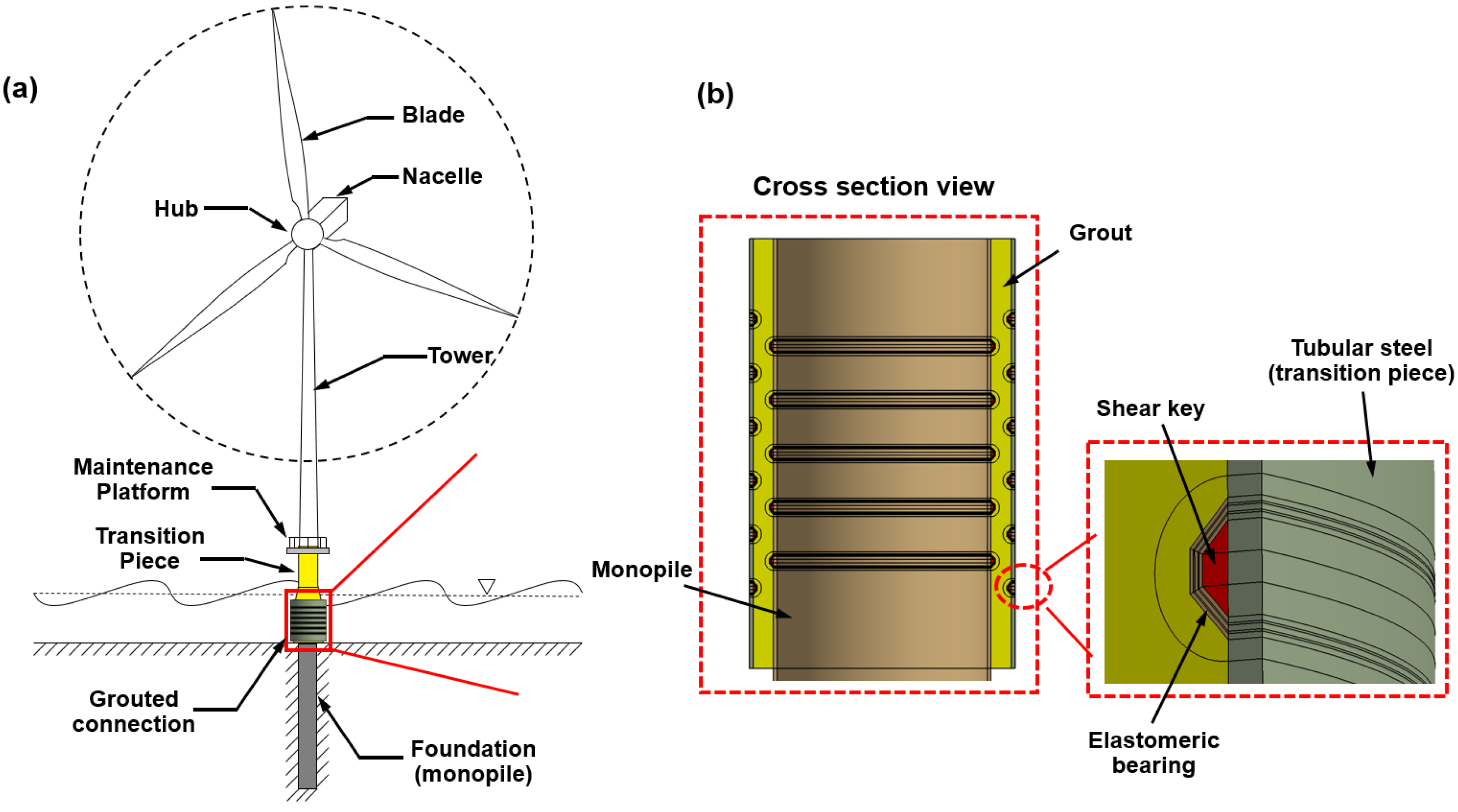
A schematic diagram of a typical grouted connection between the TP and the MP is shown in Figure 1. These connections between two components are formed by filling the annulus between two members with dissimilar dimensions with grout, where the infill acts as a load transfer medium. These GCs are effectively used in offshore drilling and production platform jackets, as well as wind turbine structures.
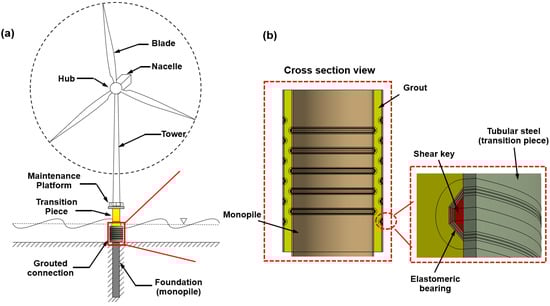
Figure 1.
(a) Schematic diagram of GC connecting the transition piece and monopile, and (b) sectional view of the GC model used in this paper.
Generally, offshore wind turbine structures are designed according to ISO 19902 [17], IEC 61400–3-1 [18], DNV-OS-J101 [19], and other internationally accepted design standards and support structure protection standards (safety standards). In particular, the requirements for material certificates, as well as testing and handling procedures of DNVGL-ST-0126, provide clear analysis methods for GCs and the design criteria for shear keys that should be complied with, while the criteria for analysis and verification through the FE analysis of GCs are outlined in DNVGL-RP-0419. Equation (1) gives the maximum nominal radial contact pressure () between the top and bottom of the GC due to the applied bending moment [20,21].
where is the effective spring stiffness of the shear key, is the characteristic friction coefficient (=0.7), is the outer radius of the MP, is the outer radius of the TP, is the thickness of the MP, is the thickness of the TP, is the effective length of the GC (), is the length of the GC, and is the nominal thickness of the grout. Equation (2) expresses the effective spring stiffness per unit length around the GC for shear keys [22].
where is the effective vertical distance of the shear key (), is the vertical center distance of two adjacent shear keys, is the width of the shear key, is the Young’s modulus of the steel, is the Poisson’s ratio of the steel, is the number of effective shear keys, and is the design factor (1.0 when calculating the action force of the shear key and 0.5 when calculating the maximum nominal radial contact pressure). Equation (3) indicates the force per unit length in the circumferential direction of the shear key due to the bending moment and the axial force.
where is the weight of the superstructure, including the total weight of the TP. At one shear key, the average force per unit length along the circumference is as expressed in Equation (4), and the characteristic interfacial shear capacity of the GC is as expressed in Equation (5).
where is the height in the radial direction from the interface between the grout and the tubular steel, is the diameter of the pile, and is the stiffness parameter in the radial direction, as defined by Equation (6) below.
where is the Young’s modulus of the grout and is the characteristic compressive strength (MPa) of a 75 mm cube. The characteristic capacity per unit length of one shear key is as expressed in Equation (7), and the design capacity is as expressed in Equation (8).
According to other studies of pile-to-sleeve GC, typical shear key types are divided into a weld bead, flat bar with fillet weld, and round bar with fillet weld [23]. In this study, the shear key of the flat bar with fillet weld type was selected as the research model because it is the most commonly used among them. Moreover, we expect that it would be relatively difficult to manufacture the round shape of the shear key reflecting the precise radius of curvature of the elastomeric bearing. The requirements for the shape dimensions of the shear keys are as follows:
The purpose of the GC is to transfer pressure between the two tubular members to provide capacity for the loads. According to DNVGL-ST-0126, the bending moment capacity depends on the radial contact pressure, the horizontal shear resistance between the steel and the grout, and the vertical shear between the steel and the grout. It is composed of the resistance and moment resistance of the shear key. Axial load capacity is achieved using horizontal shear keys. Furthermore, the vertical shear key can be arranged on the inside or outside as necessary to provide capacity for torsional load. The design standard for GC using the shear key is as follows:
where is the force per unit length in the circumferential direction due to the bending moment and the axial force, and it is transmitted by the shear key. Equation (17) gives the requirements for the maximum nominal radial contact pressure as follows:
These GC capacity evaluations can be analyzed through FE analysis. However, uncertainties of several parameters exist in the capacity evaluation of GCs. Uncertainties relate to the element type, element quality in the stress concentration region, coefficient of friction, grout material properties, material modeling, and contact formulas. Therefore, to minimize these uncertainties, proper FE modeling is essential. The FE model covered in this paper can be found in Section 3.
2.2. Load of Ultimate Condition
The ultimate load that the offshore wind turbine receives from the surrounding environment typically consists of wind and waves, and it is obtained from the drag force of the rotor and tower against the extreme wind speed [24]. The drag force () is given in Equation (18).
where is the air density, which is directly measured or calculated from the measured temperature, pressure (atmospheric pressure), and humidity. is the area to which the drag is applied, is the drag coefficient, which is a constant for the shape of the structure to which the drag is applied, and is the wind speed.
The Morrison equation was used to calculate the wave load, and it is divided into an inertia term and a drag term, as shown in Equation (19) [25].
where is the total load applied to the structure by the wave, is the inertia force, is the drag force, is the water density, is the inertia coefficient, is the cross-sectional area of the structure perpendicular to the flow direction, and is the volume.
The loads should be calculated for extreme states estimated for various wind turbine conditions and 50 or 100 year frequencies of occurrence. The GC should receive the turbine system’s weight and the environmental load from the TP and transmit it to the MP, and it should also be able to transmit the load by distributing it through the shear keys to minimize local damage to the grout.
According to Chen et al. [26], the shear key of the GC increases the ultimate bending strength of the GC because it resists the axial load and bending moment, but the fatigue strength is reduced due to the stress concentration around the shear key. This means that the shear key used to transmit the axial load by the flexibility of the GC also transmits part of the applied bending moment; thus, it may be difficult to separately analyze the axial load and the bending moment when designing the shear key. Therefore, this paper deals with the structural analysis of the GC that simultaneously applies the ultimate axial load and the bending moment. The axial load and bending moment applied in this paper were calculated for the 3.6 MW turbine and site conditions in Table 1, and the load values are shown in Table 2.

Table 1.
Applied site conditions.
Table 2.
Applied ultimate load.
3. Finite Element Model
In order to determine how the structural response that the grout receives from the ultimate load changes through the installation of the elastomeric bearings, as a control group, an analysis of the GC without the elastic members was performed, and this case is called S3 in this paper. The dimension of S3 was designed to satisfy the standard of DNVGL-ST-0126, and it was obtained to have sufficient resistance to the calculated load of Table 2 through (1) only the monopile’s element model used for parametric analysis of diameter and thickness, and (2) the GC element model without elastomeric bearing used for parametric analysis of shear key’s height. The details of the main dimensions and material properties of steel members are shown in Table 3 and Table 4, respectively. A cross-section of GC with shear keys is shown in Figure 2a. The elastomeric bearing is a member in which rubber plates and steel plates are alternately stacked [27]. While previous papers related to this focused on the study of the structural characteristics of the elastomeric bearing itself, this paper focused on the structural response of the grout when the elastomeric bearing is installed. However, there is no design standard for the elastomeric bearing applied to the shear key of the GC. Therefore, the requirements for dimensions and material properties in the design standard for elastic members for supporting bridges, which are related design standards in Korea, were referred to. The materials of the elastomer suggested in this design standard are chloroprene rubber (CR) and natural rubber (NR), and since the chemical properties of the two materials, as well as the mechanical properties, are different, these were applied as parameters according to [28]. Table 5 lists the structural properties of CR and NR [29]. For the steel plates, the same material as the tubular steel was used. Therefore, the second and third analysis cases were models in which elastomeric bearings using CR (S-E1) and NR (S-E2), respectively, were applied as materials for rubber plates. According to this standard, the thickness of the rubber plate should be 8 mm, and at least two elastomers must be used. Although the thickness of the upper and lower rubber plates is stipulated to be 2.5 mm to prevent delamination, the rubbers were designed to be 8 mm, as it is not expected that delamination would occur because it surrounds the shear key, as shown in Figure 2b, and the thickness of the steel plate was 3 mm. A grout gap occurs as much as the difference between the outer diameter of the MP and the inner diameter of the TP. As mentioned above, the grout thickness was determined according to the international design standard. According to this standard, the standard range of the shear key and TP was determined through the dimensions of the MP, and the general (average) dimensions were used for representativeness of the experiment. Therefore, the grout thickness was 420 mm, and the outer diameter of the TP was determined to be 5500 mm. The generated elements of S-E1 and S-E2 are shown in Figure 3, and, through this, the shape of the elastomeric bearing designed to cover the trapezoidal shear key could be confirmed.
Table 3.
Dimensions of grouted connection with shear keys.
Table 4.
Structural material properties of grouted connection.
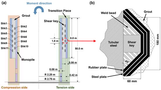
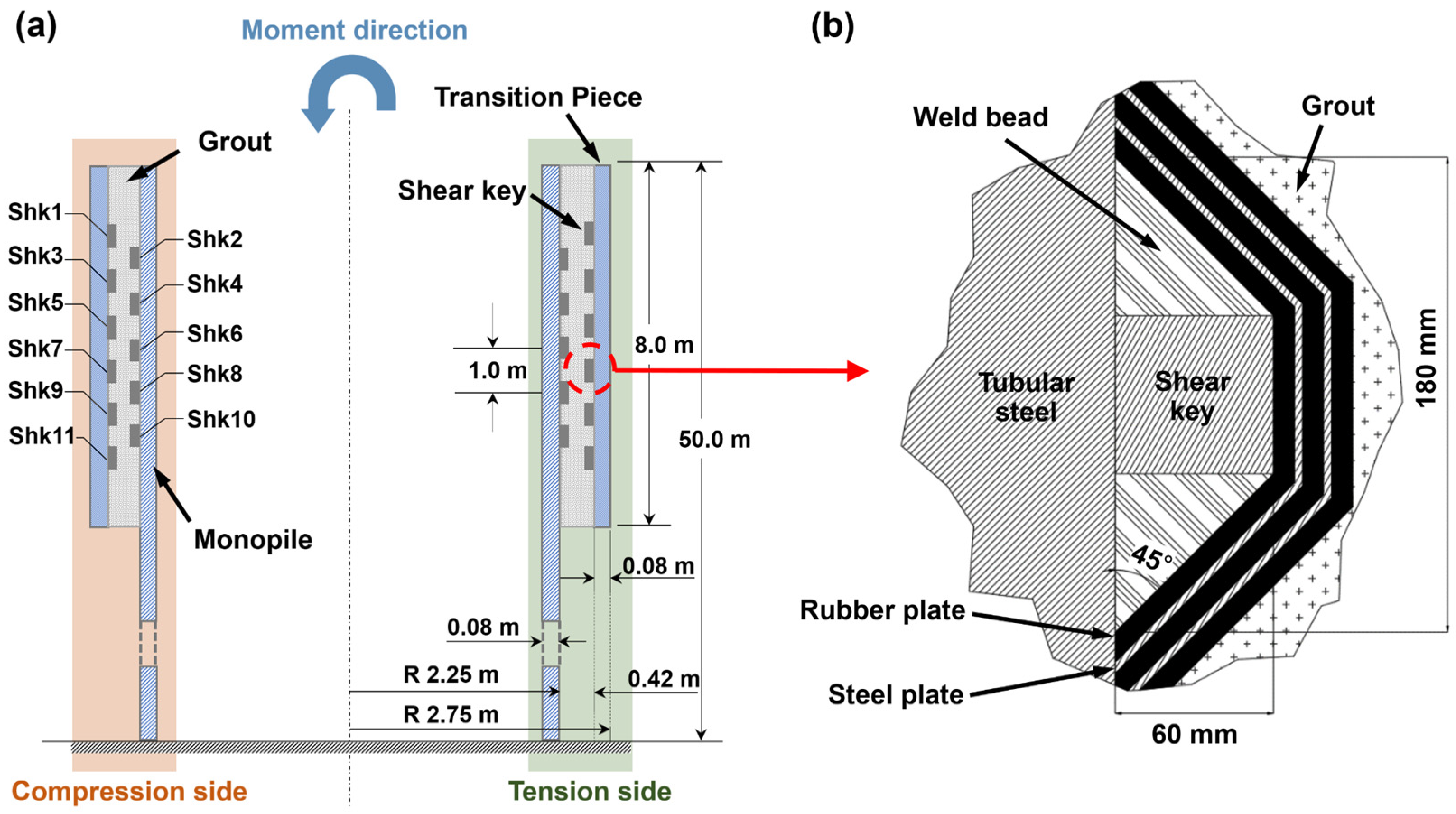
Figure 2.
Cross-section of (a) grouted connection with shear key’s name tags and (b) a shear key installed with elastomeric bearing.
Table 5.
Material properties of rubber plates (reconfigured).
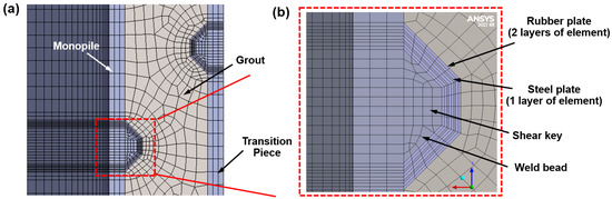
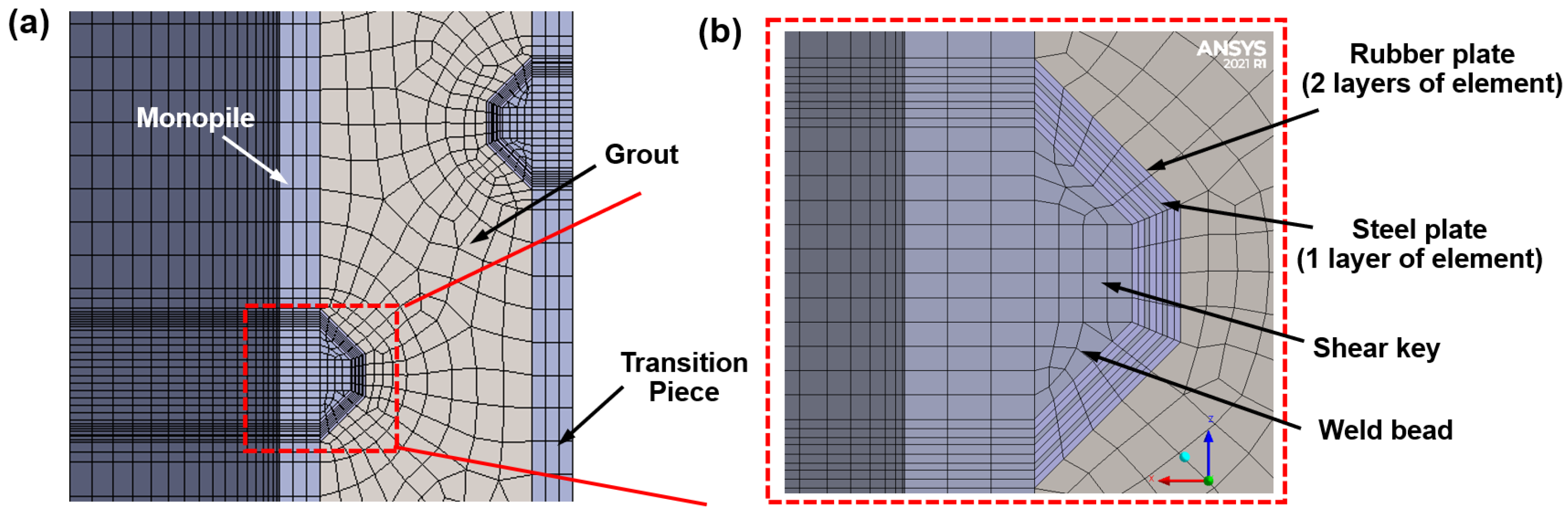
Figure 3.
Cross-section of FE model of (a) one pair of shear keys and (b) elastomeric bearing.
Most of the elements were created as hexahedral elements with 20 nodes (SOLID186) to minimize the number of elements. The element model of the elastomeric bearing had a total thickness of 30 mm. Two steel plates with a thickness of 3 mm were divided into one layer, and three rubber plates with a thickness of 8 mm were divided into two layers. In order to smoothly transfer the initial load to the surrounding components of the elastomeric bearing, it is better to match the nodes of the contact. Increasing the element layer in the thickness direction greatly affects the quality of the mesh, which not only increases the memory of the analysis model, but also has a significant effect on nonlinearity convergence. Therefore, the stress on the elastomeric bearing was not analyzed in this paper because it was modeled with too few element layers in the thickness direction of each plate. Moreover, in order to capture the load concentrated in the grout in contact with the elastomeric bearing, which is a relatively small component of the GC, it was divided into 300 layers in the tangential direction and seven layers in the radial direction. The elements of the monopile were divided by 200 mm in length of 42 m downward from the bottom of the GC in the axial direction so that the inclination result of the pile head was sufficiently reliable. Then, to compensate for the mesh quality of the GC, 8 m above the bottom of the GC was created with an element size of about 70 mm. It was modeled as three layers with respect to the thickness direction.
Structural analysis of S-E1 and S-E2 applied nonlinear material properties and non-linear contact, and the respective numbers of elements in the model that succeeded in convergence were about 460,000 and 700,000. Due to the thin thickness of the steel plate compared to the overall size of the model, the element’s aspect ratio of the elastomeric bearing was slightly reduced to about 7.0 for node matching on the contact interface. When the entire analysis model was configured with good grid quality according to the maximum thickness of the elastomeric bearing, the number of elements exceeded 10 million, thus resulting in very low analysis efficiency. The aspect ratios of other elements aside from elastomeric bearings were the same as that of S3.
Rough contact elements were generated for the interface between the rubber plate and the grout with contact element type of CONTA174 and TARGE170. The frictional coefficient of contact between tubular steel and grout was set to 0.7, as per DNVGL-ST-0126, and a penalty formulation was used with element type and the same rough contact elements. As a simplification assumption to minimize the nonlinear contact elements of the analysis, the bonded contact condition was set for the rubber plates in contact with the tubular steel members where delamination is not expected, and no contact was created at the interface between the rubber plates and the steel plates. However, these need to be verified through further analysis.
According to [33], the strain energy function of the Mooney–Rivlin hyper-elastic constitutive model is expressed as a function of strain invariants . The form of the strain energy density function for two terms in the Mooney–Rivlin models is given as
where and are material constants, is the material incompressibility parameter, is the initial shear modulus, and is the initial bulk modulus. The main difference when applying CR and NR is the difference in chemical reactivity, but it is expected that the elastomeric bearing to be installed in the GC will rarely be exposed to reactive materials. In terms of structural strength, there is a slight difference in density, and the tensile strength is higher in NR. Therefore, both materials were applied as parameters.
4. Results and Discussion
The main concern of the monopile GCs is contact failure or material failure of the grout material. Furthermore, the load transfer characteristic is one of the areas of interest for researchers aiming to distribute the stress concentration by the shear key. Therefore, the main concern in the structural analysis of the GC is the contact pressure on the interfaces between the grout and the shear keys or tubular steels, or the shear stress on the grout material. In this paper, the analysis results for contact pressure and shear stress were analyzed depending on whether or not an elastomeric bearing was installed. Through these two types of results, the load transfer characteristics in the variable direction of the GC could be identified.
4.1. Contact Pressure
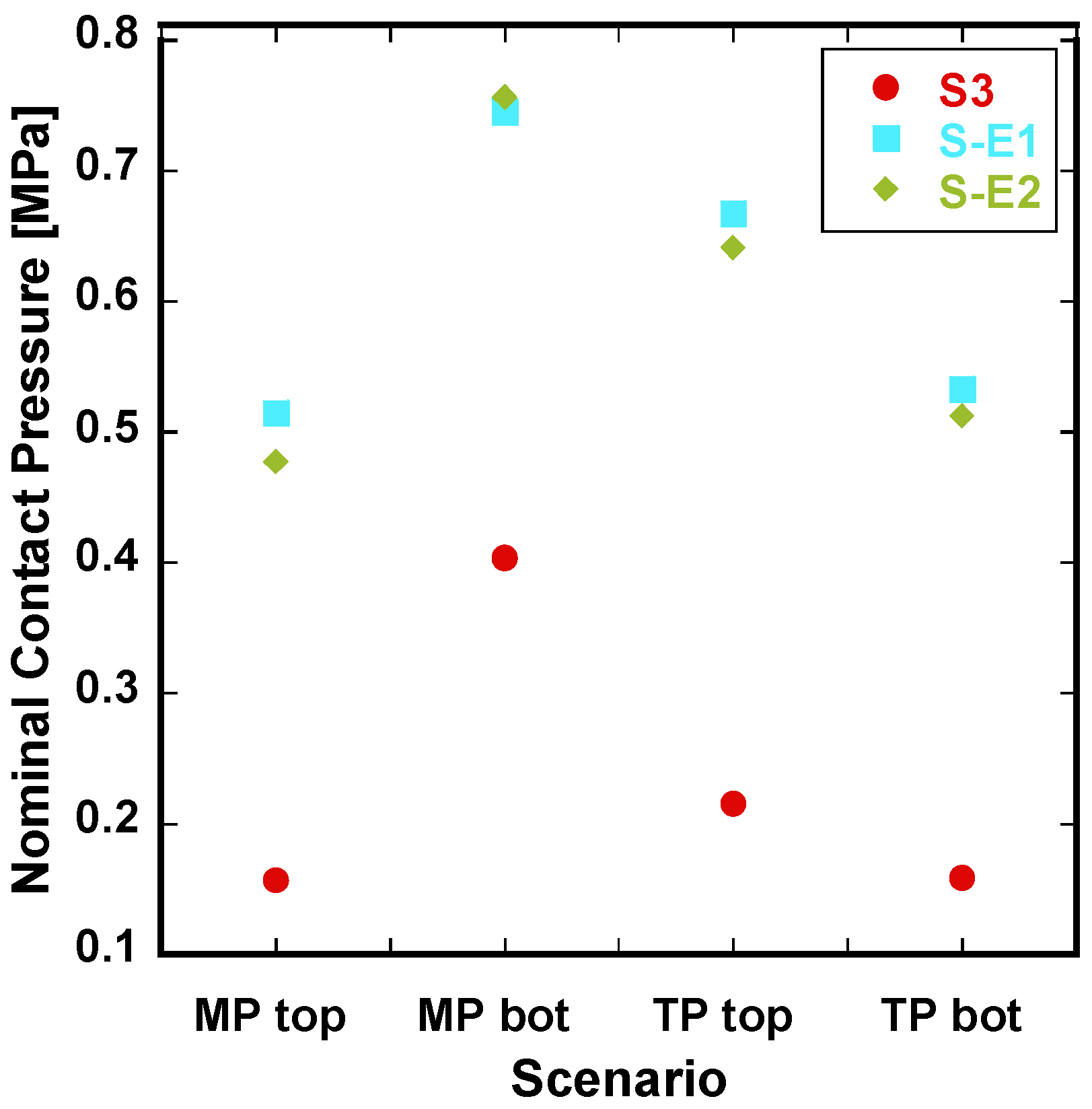
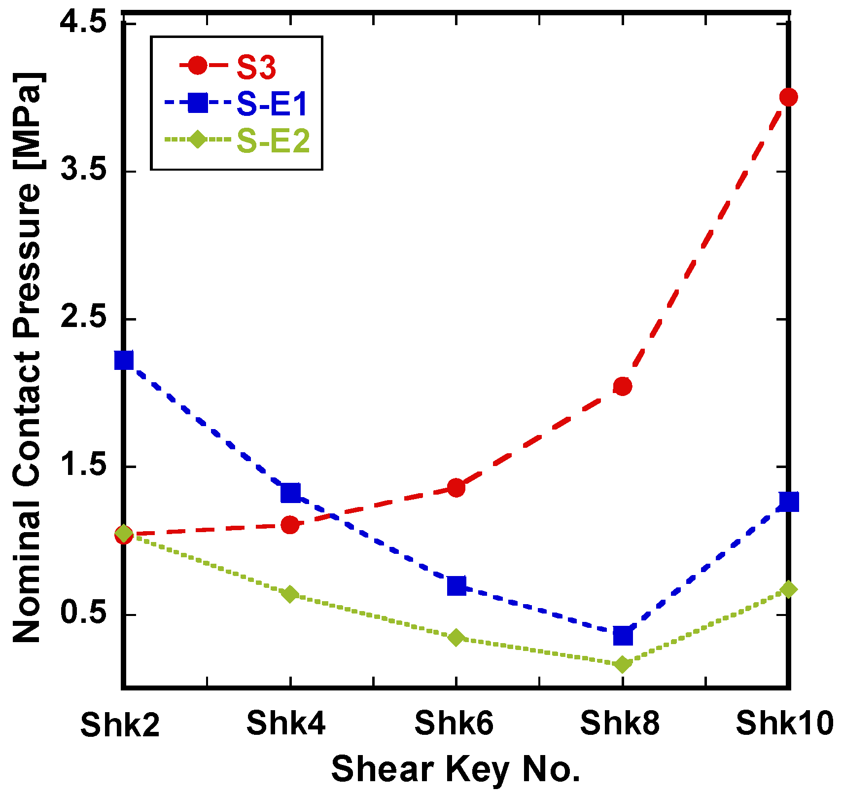
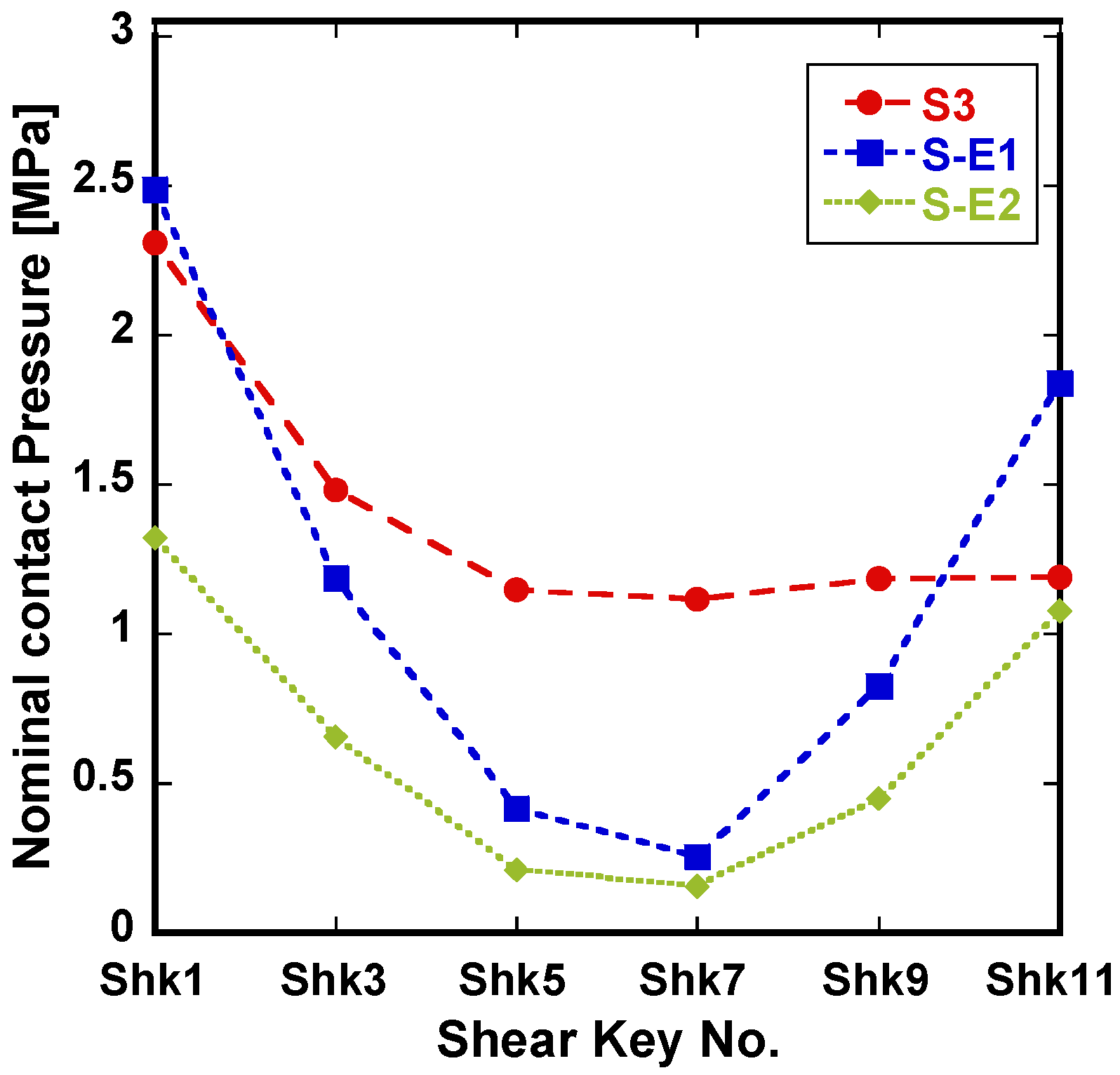
Table 6 lists the nominal contact pressures of the four areas (, , , and ) where the tubular steel and the grout come into contact with the top and the bottom of the GC, and the average nominal contact pressure of the areas () at which the 11 shear keys come into contact with the grout. The contact pressure increased about 2.5-fold when the elastomeric bearings were installed through the average of the contact pressures for all contact areas (). Specifically, the contact pressure () with the shear keys was 1.9 times lower when using NR material (S-E2) than when using CR material (S-E1). Among the contact areas with tubular steel, the contact pressure in the area in contact with the bottom side of MP was relatively high, as can be seen in Figure 4. Figure 5 and Figure 6 show the nominal contact pressure of each shear key installed in MP and TP, respectively. In the case of S3, the contact pressure increased toward the bottom side of the GC, but it generally decreased when the elastomeric bearing was applied. In addition, the nominal contact pressure at the center of the GC was relatively low with the elastomeric bearing installed.
Table 6.
Nominal contact pressure of each interface area with grout.
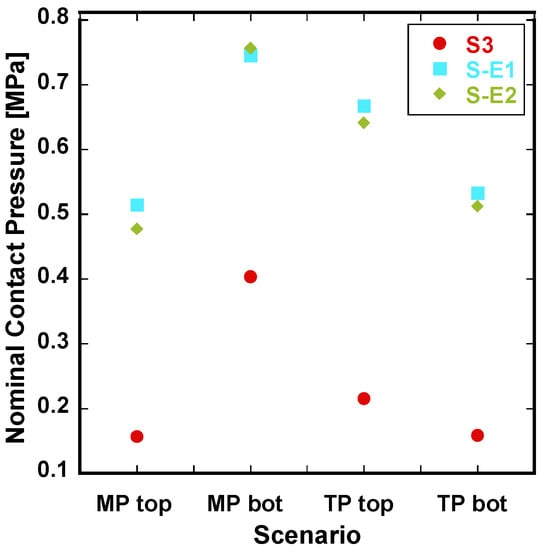
Figure 4.
Nominal contact pressure by interface areas of grout and tubular steels.
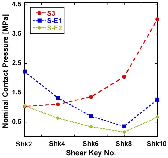
Figure 5.
Mean nominal contact pressure of MP shear keys by scenario.
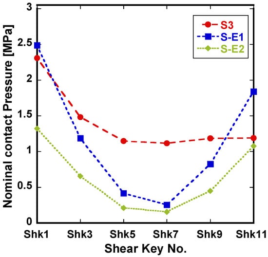
Figure 6.
Mean nominal contact pressure of TP shear keys by scenario.
4.2. Shear Stress
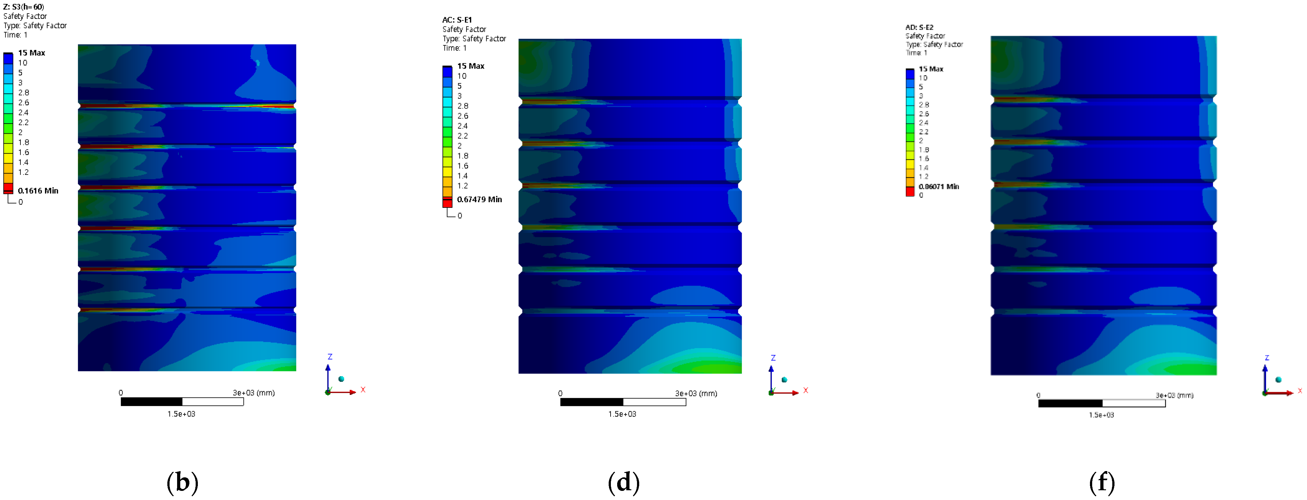
The shear stress distribution for the Mohr–Coulomb stress theory in each scenario is shown in Figure 7, and the numerical analysis results are presented in Table 7. Figure 7 shows the concentration trend of shear stress according to the installation of elastomeric bearings. When elastomeric bearings are not installed, stress concentration occurs around the shear keys; however, when elastomeric bearings are installed, the shear force is dispersed due to the strong lateral contact stiffness of the rubber plate, and the grout strut is very faint as well. Therefore, the installation of elastomeric bearings significantly reduced the concentration of shear stress.
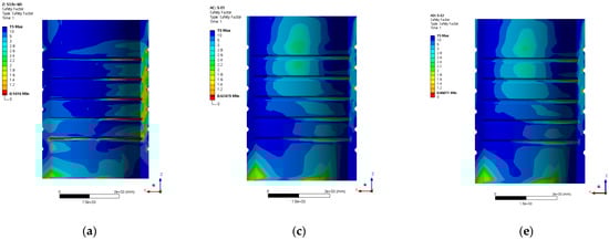
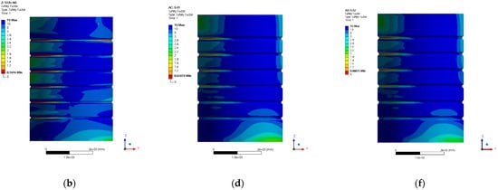
Figure 7.
Distributions of shear stress of (a) S3 with MP, (b) S3 with TP, (c) S-E1 with MP, (d) S-E1 with TP, (e) S-E2 with MP, and (f) S-E2 with TP.
Table 7.
Maximum and mean shear stress of grout for each scenario.
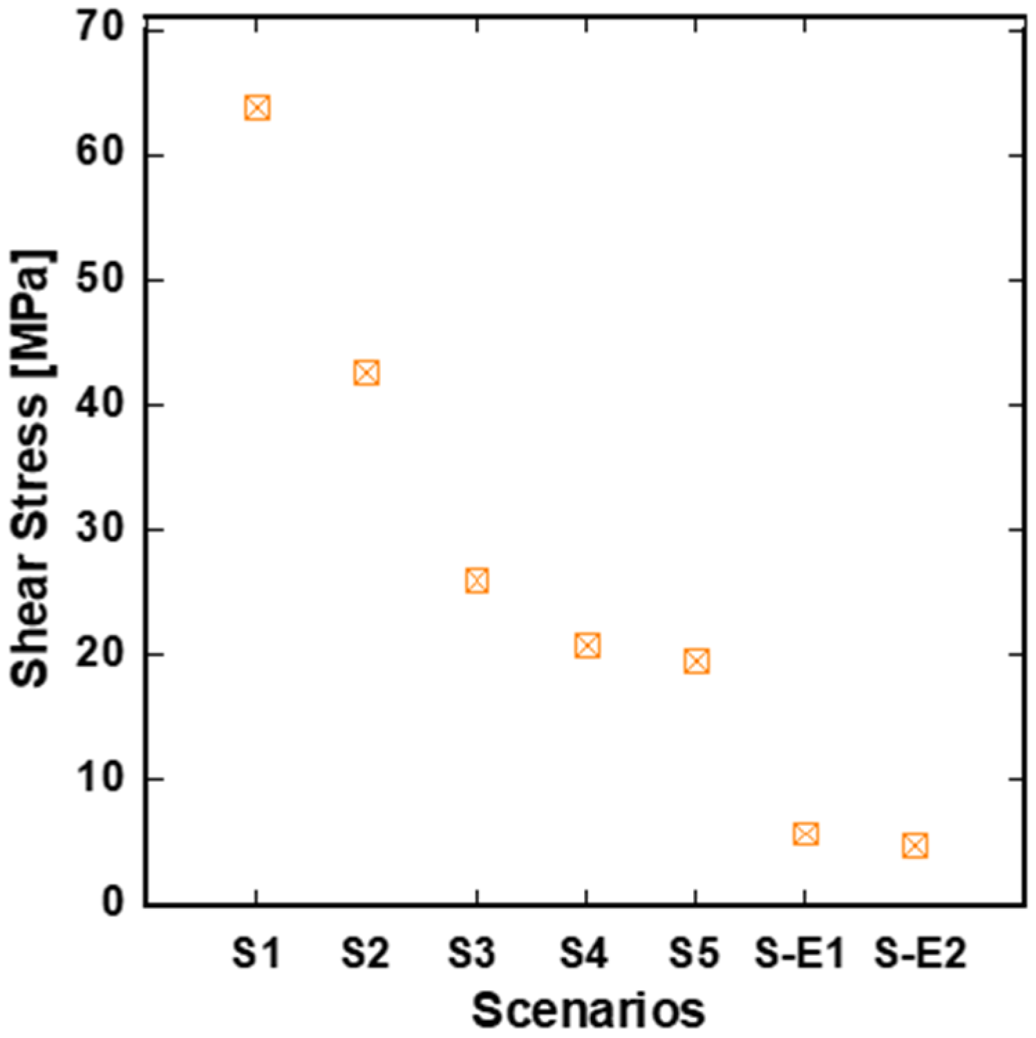
Figure 8 shows the maximum shear stress in the scenario in which the size of the shear key was increased from 20 mm (S1) to 100 mm (S5) at intervals of 20 mm without applying the elastomeric bearing. Through this, the maximum shear stress generated in S1–S5 was 19.60–63.91 MPa, and, as listed in Table 7, that in S3 was 25.95 MPa. When the elastomeric bearings were applied, the maximum shear stress values were 5.78 MPa in S-E1 and 4.90 MPa in S-E2, which were reduced by about 77–81% compared to S3.
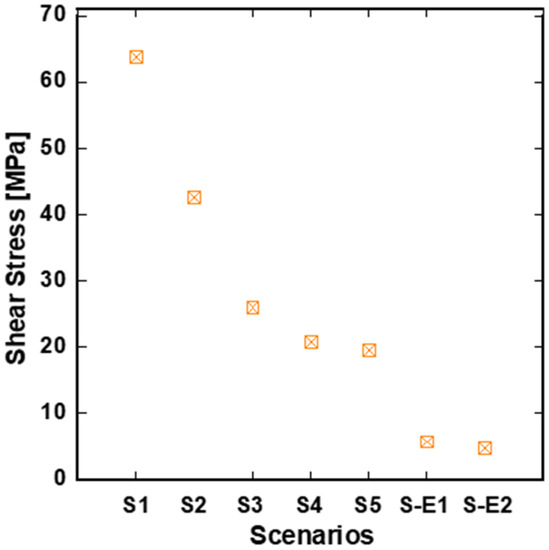
Figure 8.
Comparison of shear stress according to shear key size and installation of elastomeric bearings.
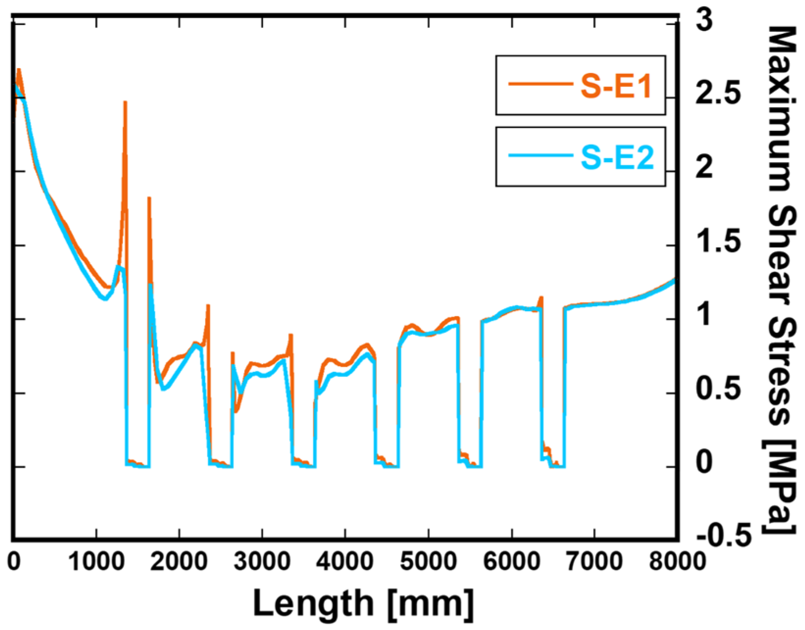
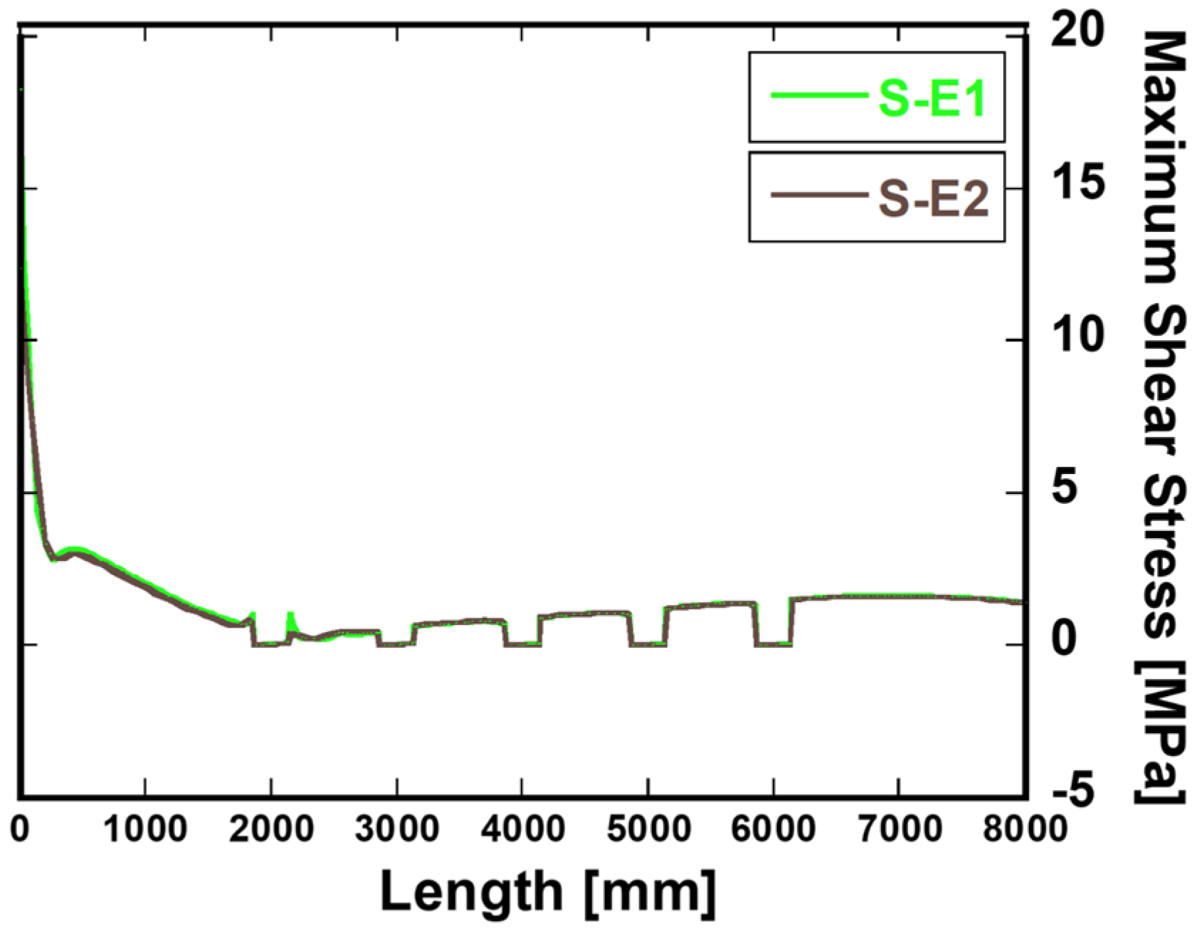
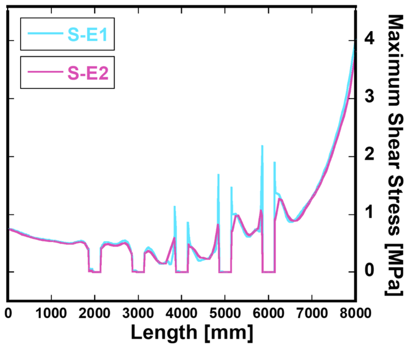
Figure 9, Figure 10, Figure 11 and Figure 12 are graphs showing the maximum shear stress at the interface of the grout, where the GC is divided into a compression part and a tension part in terms of the load direction. Through this, the maximum shear stress of the scenario using CR material for each elastomeric bearing (S-E1) was relatively high.
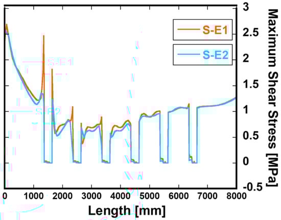
Figure 9.
Maximum shear stress at grout contact on TP of compression side.
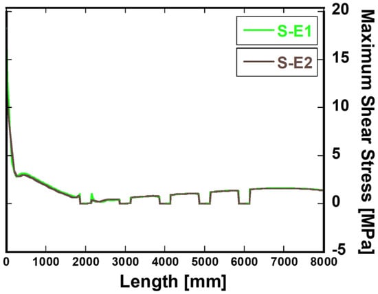
Figure 10.
Maximum shear stress at grout contact on MP of compression side.
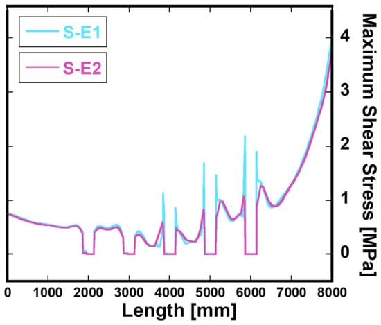
Figure 11.
Maximum shear stress at grout contact on MP of tension side.
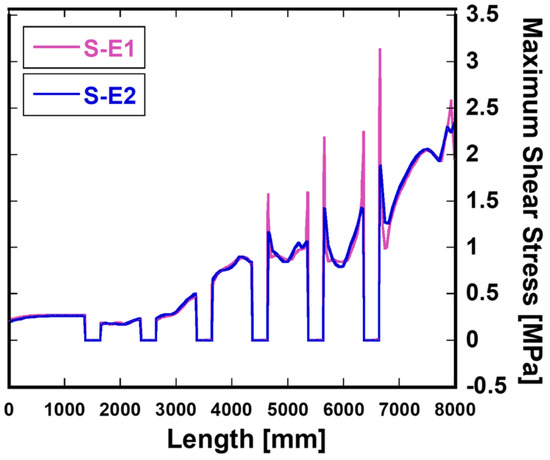
Figure 12.
Maximum shear stress at grout contact on TP of tension side.
5. Conclusions
This paper analyzed the changes in contact pressure and shear stress through a three-dimensional finite element analysis focused on whether elastomeric bearings for bridge support were installed around the shear keys of the grouted connection, and the conclusions below were derived.
First, the contact pressure analysis showed that the contact pressure for all grout contact areas increased about 2.5-fold when elastomeric bearings were installed. In particular, when the rubber plate material was used as natural rubber, the contact pressure with the shear key was 1.9 times lower than when neoprene was used. Among the contact surfaces with tubular steel, the contact pressure in the area in contact with the bottom of the monopile was the highest.
Second, the contact pressure increased toward the bottom side of the grouted connection when elastomeric bearings were not installed, but it decreased when elastomeric bearings were installed. In addition, with the installation of elastomeric bearings, the contact pressure was generally low in the central part with respect to the height direction of the grouted connection.
Third, when the shear key size was increased from 20 to 100 mm under the same conditions, the maximum shear stress was decreased from 63.91 MPa to 19.60 MPa, and, when the shear key height was 60 mm, the value of 25.95 MPa was obtained. In this paper, when the elastomeric bearing was installed, the maximum shear stress was 5.78 MPa for neoprene material and 4.90 MPa for natural rubber material, thus representing a decrease of 77–81% compared to 25.95 MPa.
Through this paper, we intend to contribute to the research on the load transfer characteristics of the grout joint and the development of design technology for the contact and material failure of the grout.
Author Contributions
Conceptualization, writing, methodology, and software, Y.-S.Y., and M.-Y.S.; validation, writing—original draft preparation, and funding acquisition, M.-Y.S. All authors read and agreed to the published version of the manuscript.
Funding
This research was funded by Korea Western Power Co., Ltd., grant number 2102001542.
Institutional Review Board Statement
Not applicable.
Informed Consent Statement
Not applicable.
Data Availability Statement
Data are available from the authors upon request.
Acknowledgments
This paper is the result of a study conducted with the support of the Korea Western Power Co., Ltd., Taean, Republic of Korea. for Advancement of Technology’s “Development of high-efficiency offshore wind farms for the southwest coast of Korea (2102001542)” project. All authors and this company consented to this acknowledgment.
Conflicts of Interest
The authors declare no conflict of interest.
References
- Sun, X.; Huang, D.; Wu, G. The current state of offshore wind energy technology development. Energy 2012, 41, 298–312. [Google Scholar] [CrossRef]
- Weiss, C.V.C.; Guanche, R.; Ondiviela, B.; Castellanos, O.F.; Juanes, J. Marine renewable energy potential: A global perspective for offshore wind and wave exploitation. Energy Convers. Manag. 2018, 177, 43–54. [Google Scholar] [CrossRef]
- Klose, M.; Mittelstaedt, M.; Mulve, A. Grouted connections-offshore standards driven by the wind industry. In Proceedings of the Twenty-Second International Offshore and Polar Engineering Conference, Rhodes, Greece, 17–22 June 2012. [Google Scholar]
- Sánchez, S.; López-Gutiérrez, J.-S.; Negro, V.; Esteban, M.D. Foundations in offshore wind farms: Evolution, characteristics and range of use. Analysis of main dimensional parameters in monopile foundations. J. Mar. Sci. Eng. 2019, 7, 441. [Google Scholar] [CrossRef] [Green Version]
- Schallenberg-Rodríguez, J.; García Montesdeoca, N. Spatial planning to estimate the offshore wind energy potential in coastal regions and islands. Practical case: The Canary Islands. Energy 2018, 143, 91–103. [Google Scholar] [CrossRef]
- Nonveiller, E. Grouting Theory and Practice; Elsevier: Amsterdam, The Netherlands, 2013. [Google Scholar]
- Schaumann, P.; Bechtel, A.; Lochte-Holtgreven, S. Grouted joints for offshore wind turbine jackets under full reversal axially loading conditions. In Proceedings of the Twenty-third International Offshore and Polar Engineering Conference, Anchorage, AK, USA, 30 June–5 July 2013. [Google Scholar]
- Dallyn, P.; El-Hamalawi, A.; Palmeri, A.; Knight, R. Experimental testing of grouted connections for offshore substructures: A critical review. Structures 2015, 3, 90–108. [Google Scholar] [CrossRef] [Green Version]
- Johnston, C.; Doré, M. Comparison of the Fatigue Performance of Galvanised M72 Bolts With Design Standard Recommendations. In Proceedings of the ASME 2021 40th International Conference on Ocean, Offshore and Arctic Engineering, Online, 21–30 June 2021. [Google Scholar]
- Schaumann, P.; Raba, A.; Bechtel, A. Impact of Contact Interface Conditions on the Axial Load Bearing Capacity of Grouted Connections. In Proceedings of the European Wind Energy Association Conference EWEA 2013, Vienna, Austria, 4–7 February 2013. [Google Scholar]
- Ibrahim, R. Recent advances in nonlinear passive vibration isolators. J. Sound Vib. 2008, 314, 371–452. [Google Scholar] [CrossRef]
- Jie, Y.; Yuan, H.; Zhou, H.; Yu, Y. Bending moment calculations for piles based on the finite element method. J. Appl. Math. 2013, 2013, 784583. [Google Scholar] [CrossRef] [Green Version]
- Khodair, Y.; Abdel-Mohti, A. Numerical analysis of pile–soil interaction under axial and lateral loads. Int. J. Concr. Struct. Mater. 2014, 8, 239–249. [Google Scholar] [CrossRef] [Green Version]
- Achmus, M.; Thieken, K. On the behavior of piles in non-cohesive soil under combined horizontal and vertical loading. Acta Geotech. 2010, 5, 199–210. [Google Scholar] [CrossRef]
- Conte, E.; Pugliese, L.; Troncone, A.; Vena, M. A simple approach for evaluating the bearing capacity of piles subjected to inclined loads. Int. J. Geomech. 2021, 21, 04021224. [Google Scholar] [CrossRef]
- Graine, N.; Hjiaj, M.; Krabbenhoft, K. 3D failure envelope of a rigid pile embedded in a cohesive soil using finite element limit analysis. Int. J. Numer. Anal. Methods Geomech. 2021, 45, 265–290. [Google Scholar] [CrossRef]
- Saigal, R.K.; Dolan, D.; Der Kiureghian, A.; Camp, T.; Smith, C.E. Comparison of design guidelines for offshore wind energy systems. In Proceedings of the Offshore Technology Conference, Houston, TX, USA, 30 April–3 May 2007. [Google Scholar]
- Roach, S.; Park, S.M.; Gaertner, E.; Manwell, J.; Lackner, M. Application of the new IEC international design standard for offshore wind turbines to a reference site in the massachusetts offshore wind energy area. J. Phys. Conf. Ser. 2020, 1452, 012038. [Google Scholar] [CrossRef]
- Hopstad, A.L.H.; Ronold, K.O.; Slätte, J. Design Standard for Floating Wind Turbine Structures. Doc. Hist. 2013, 194. Available online: https://www.sintef.no/globalassets/project/deepwind-2013/deepwind-presentations-2013/posters/hopstad_poster.pdf (accessed on 23 November 2021).
- Tziavos, N.I.; Hemida, H.; Metje, N.; Baniotopoulos, C.J. Non-linear finite element analysis of grouted connections for offshore monopile wind turbines. Ocean. Eng. 2019, 171, 633–645. [Google Scholar] [CrossRef] [Green Version]
- Sunday, K.; Brennan, F. A review of offshore wind monopiles structural design achievements and challenges. Ocean. Eng. 2021, 235, 109409. [Google Scholar] [CrossRef]
- Grech, J.; Antunes, E. Zirconia in dental prosthetics: A literature review. J. Mater. Res. Technol. 2019, 8, 4956–4964. [Google Scholar] [CrossRef]
- Krahl, N.W.; Karsan, D.I. Axial strength of grouted pile-to-sleeve connections. J. Struct. Eng. 1985, 111, 889–905. [Google Scholar] [CrossRef]
- DNV GL. STANDARD DNV GL ST 0437: Loads and Site Conditions for Wind Turbines; DNV GL: Oslo, Norway, 2016. [Google Scholar]
- Morison, J.; Johnson, J.; Schaaf, S.A. The force exerted by surface waves on piles. J. Pet. Technol. 1950, 2, 149–154. [Google Scholar] [CrossRef]
- Chen, T.; Wang, X.; Zhao, Q.; Yuan, G. A numerical investigation on grouted connections for offshore wind turbines under combined loads. J. Mar. Eng. Technol. 2019, 18, 134–146. [Google Scholar] [CrossRef]
- Stanton, J.F.; Roeder, C.W. Elastomeric Bearings Design, Construction, and Materials; NCHRP Report; Transportation Research Board: Washington, DC, USA, 1982; p. 248. [Google Scholar]
- Yoon, H.; Kwahk, I.J.; Kim, Y.J. A study on the ultimate performances of elastomeric bearings in Korea. KSCE J. Civ. Eng. 2013, 17, 438–449. [Google Scholar] [CrossRef]
- Wadham-Gagnon, M.; Hubert, P.; Semler, C.; Païdoussis, M.P.; Vézina, M.; Lavoie, D. Hyperelastic modeling of rubber in commercial finite element software (ANSYS). In Proceedings of the Conference on SAMPE 2006, Long Beach, CA, USA, 30 April–4 May 2006; Volume 6. [Google Scholar]
- Schaffer, W.; Seo, J.; Choi, E.; Lee, J. Optimized retrofit design of in-service monopile foundation offshore wind turbine transition zone. Eng. Struct. 2020, 220, 111001. [Google Scholar] [CrossRef]
- Lotsberg, I.; Serednicki, A.; Lervik, A.; Bertnes, H.J.S. Design of grouted connections for monopile offshore structures: Results from two joint industry projects. Stahlbau 2012, 81, 695–704. [Google Scholar] [CrossRef]
- Chen, B.-Q.; Soares, C.G. Experimental and numerical investigation on welding simulation of long stiffened steel plate specimen. Mar. Struct. 2021, 75, 102824. [Google Scholar] [CrossRef]
- Kumar, N.; Rao, V.V. Hyperelastic Mooney-Rivlin model: Determination and physical interpretation of material constants. Parameters 2016, 2, 43–46. [Google Scholar]


Publisher’s Note: MDPI stays neutral with regard to jurisdictional claims in published maps and institutional affiliations. |
© 2022 by the authors. Licensee MDPI, Basel, Switzerland. This article is an open access article distributed under the terms and conditions of the Creative Commons Attribution (CC BY) license (https://creativecommons.org/licenses/by/4.0/).