Abstract
MEMS-based LIDAR has the advantages of fast-scanning, simple structure, small volume, and light weight, which make it a hot topic for 3D imaging. In order to overcome the limited scanning angle of the current MEMS mirrors, a large angle MEMS-based optical scanning system was designed using telephoto structure. In this design an f-θ lens group is used for flat field scanning and a symmetrical cemented lens group is used for angle expansion. The principle of this system is discussed in detail and an optical design is implemented by ZEMAX software. The designed system realized a scanning angle as large as 57° and is in excellent linear relation with the tilt angle of the MEMS mirror. At the target distance of 100 m, the maximum RMS radius of the light spot is only 7 cm. This optical scanning system shows a significant application potentiality for 3D imaging LIDAR.
1. Introduction
In recent years, in the fields of environmental monitoring, engineering inspection, unmanned driving, military surveying and mapping, the detection demand of imaging LIDAR has grown rapidly, and these applications have made the new generation of imaging LIDAR gain widespread attentions [1,2,3,4,5,6]. LIDAR is a sensor that uses a laser beam to obtain information such as the precise position and size of an object. Its working principle is to send a laser beam signal to the target object to be measured, then compare the target echo with the transmitted signal to obtain the position information and realize the detection and recognition of the target [7,8].
Currently available optical scanning methods for imaging LIDAR consist of flash, optical phased array (OPA), mechanical rotating, MEMS mirror scanning, etc. [9]. Flash LIDAR is of solid form, so in a strict sense, it is not an optical scanning form. It directly illuminates the surface of the object to be measured through emitting a surface laser, and the detector composed of a pixel array realizes the reception. Each independent pixel unit only can receive a small part of the echo power, which limits its ability to image far targets [10,11]. OPA LIDAR is of solid-state scanning form with no internal mechanical drive structure. It uses array laser sources and works by the principle of multiple beams interference. By controlling the phase difference of each sub-light source, the main beam direction can behave scanning. OPA technology requires that the size of the sub-light source of the array must be less than half of the working wavelength, which results in great difficulty with chip processing. At the same time, the main beam is easily affected by the side lobe beam caused by interference, which causes energy leakage and affects the detection resolution [12]. The mechanical rotary type is relatively mature, but it has shortcomings of high-power consumption, large volume, cumbersome optical structure, and complicated assembly, resulting in low production efficiency and high cost [13]. On the contrary, MEMS technology directly integrates the micro-scanning mirror into the silicon chip, which is only a few millimeters in size. The mirror rotates through electrostatic, electromagnetic, electrothermal, piezoelectric or other driving methods, which greatly reduces the size of the system and increases production efficiency. The study of LIDAR based on MEMS mirrors is significant for the development of the new generation of miniaturized, low-cost imaging LIDAR [14,15,16].
MEMS scanning technology is a quasi-solid form with high flexibility. It combines microelectronics, mechanical and optical technologies, and uses a drive circuit to achieve the desired field of view (FOV) and control the angle accurately [17,18]. However, due to the high resonant frequency of MEMS mirror, which is above 200 Hz, the scanning angle is usually within ±10°, which cannot meet the large field of view detection requirements for imaging LIDAR. An auxiliary optical system must be used to extend its field of view [19,20,21]. So, researching auxiliary angle extending optical system design is quite significant for the MEMS scanning LIDAR. This work designed an optical scanning system for frequency modulated continuous wave (FMCW) LIDAR, which can achieve a large field of view of 57 degrees, and uniformly scanning with a 7 cm light spot for a target at 100 m.
2. Basic Principles of the Scanning System
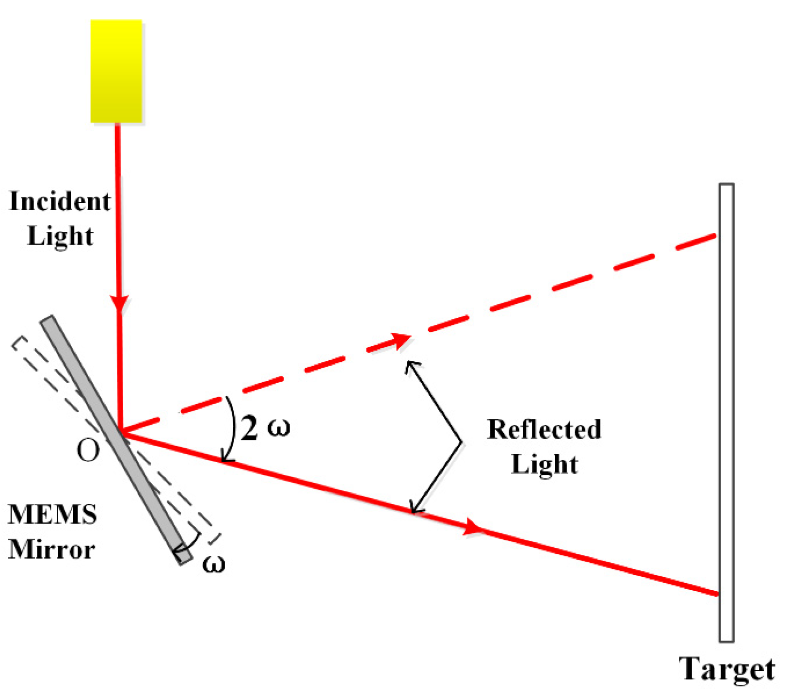
The mechanical rotation angle of the MEMS mirror is generally within ±5°. According to the principle of plane mirror reflection, when the direction of the incident light remains unchanged and the plane mirror rotates by ω degrees, the reflection angle of the light will change by 2ω degrees, so after passing through the MEMS mirror, the scanning angle of the beam is usually within ±10°, as shown in Figure 1. For LIDAR, especially car-level imaging LIDAR for autonomous driving technology, the scanning field of view requires at least 40°, so special optical design is needed to extend the FOV of MEMS mirror. At present, the commonly used method to extend FOV is adding an optical system with telescope structure, which is to sequentially pass the laser source through a positive lens, a MEMS mirror, and a negative lens. This method has a certain aberration and a large divergence angle. The optical scanning system design in this paper adopts an f-θ lens that often used in laser scanning and laser marking for flat field focusing and uses a rear positive lens group to collimate the laser beam and extend the scanning angle.
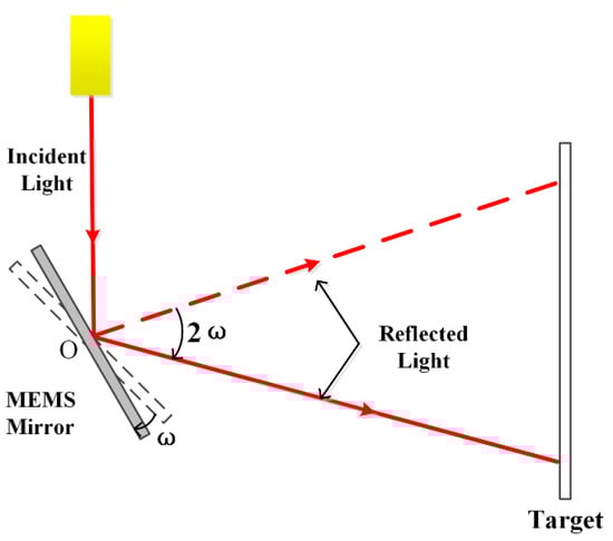
Figure 1.
The relationship between MEMS mechanical angle and the field of view.
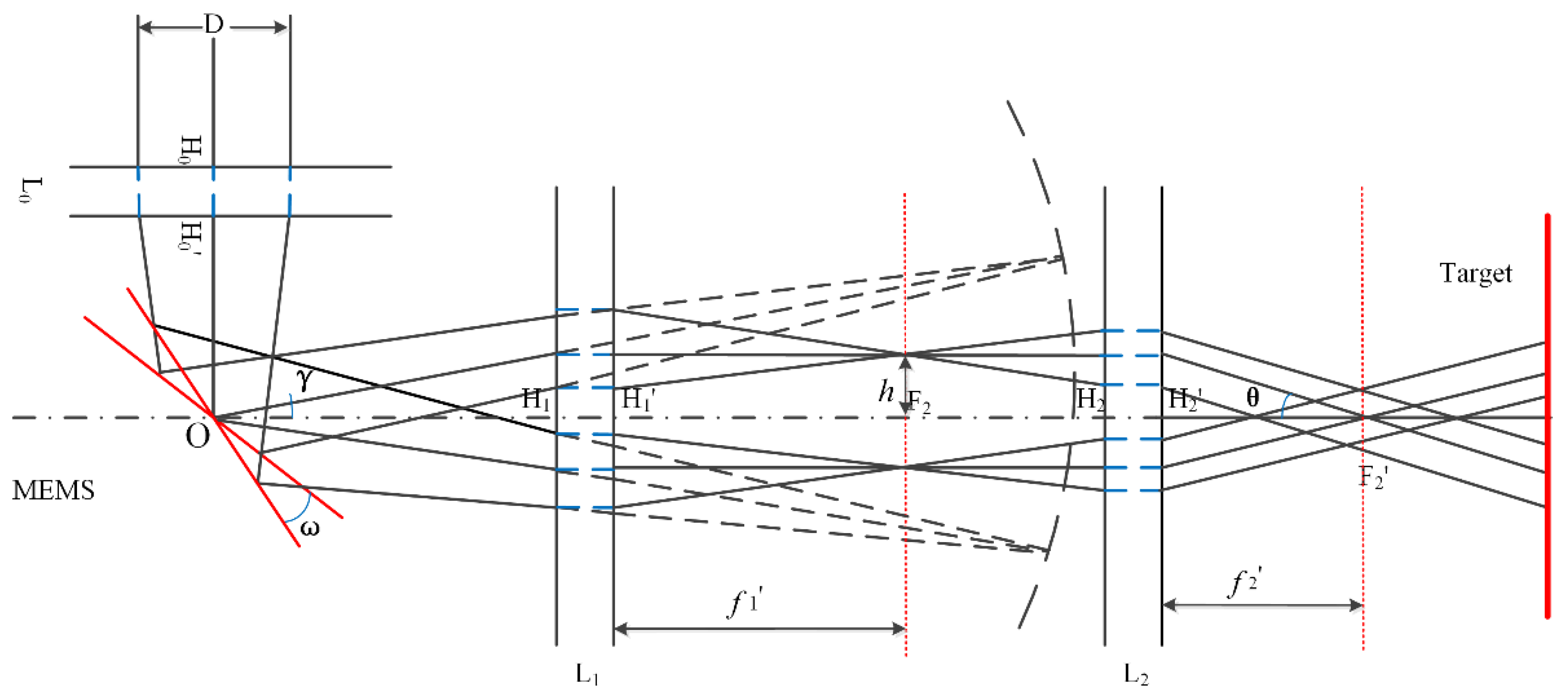
The schematic diagram is shown in Figure 2. Hi and Hi’ are object principal plane and image principal plane of the lens groups, respectively. The laser beam is focused by the cemented lens L0 and completely irradiate into the effective area of the MEMS mirror. After being reflected by the MEMS mirror, the f-θ lens L1 is used to correct the image surface into a plane and focus the beam. Then the laser passes through the symmetrical cemented positive lens group L2, whose object focal plane coincides with the image focal plane of the f-θ lens. So L2 collimates the scanning beam.
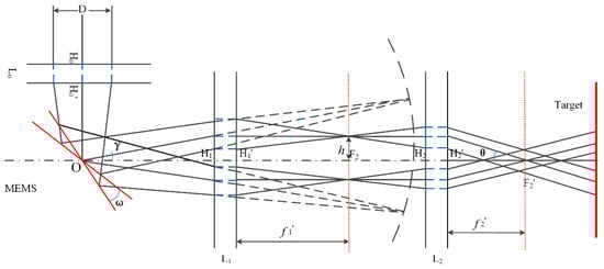
Figure 2.
Schematic diagram of MEMS scanning system.
Assume the focal length of the f-θ lens L1 is , and that of the collimating lens L2 is , then according to the geometric optics theory, the image height h of the beam after passing through the f-θ lens can be obtained:
where γ is the scanning field angle of the MEMS mirror. For the collimating positive lens group L2, its object height h satisfies:
So, the field of view of the scanning system θ is:
From Equation (3) we can see that if , the system scanning angle will be extended.
3. Scanning Optical System Design
The design was implemented by ZEMAX software, which works by ray tracing [22]. The laser source in this work is a tunable semiconductor from NewFocus, which is suitable for FMCW LIDAR. Its center wavelength is 1550 nm, the wavelength scanning range is from 1520 nm to 1570 nm, the maximum beam divergence angle is 1.5 mrad and the maximum output power is 50 mW. To simulating this laser source, in the normal column setting of ZEMAX software, the aperture type is selected as object space numerical aperture (NA), the value is 0.00075, the apodization type is Gaussian, and the factor is 1.
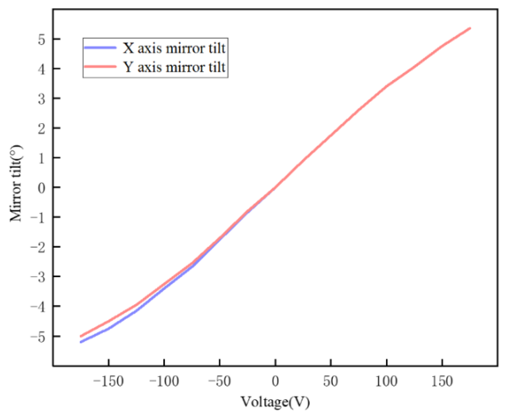
This design uses the MEMS mirror model S40919 manufactured by Mirrorcle. The effective diameter of the mirror is 5 mm, and the rotation range is ±5°. It works based on the principle of electrostatic driving. The relationship between the driving voltage and the tilt angle provided by the mirror manufacturer is shown in Figure 3. The parameters are listed in Table 1.
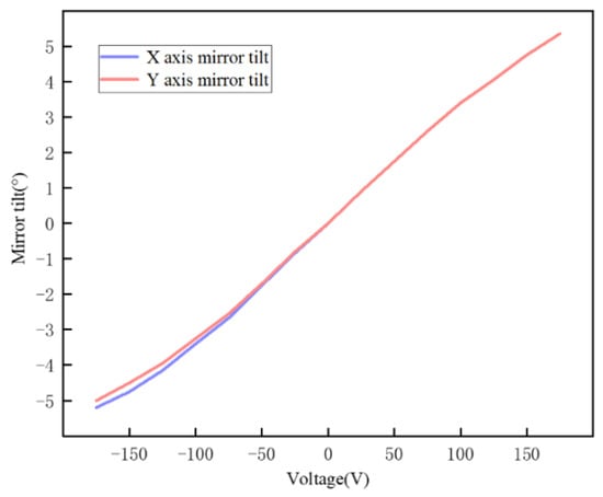
Figure 3.
The relationship between drive voltage and tilt angle.

Table 1.
MEMS mirror parameters of S40919.
As shown in Figure 2, the laser beam emitted by the semiconductor laser should first be focused by a positive lens to completely illuminate the effective mirror surface without causing beam leakage. A double cemented lens L0 with a focal length of 80 mm is used to eliminate spherical aberration. The object distance between the laser source and L0 is 1207 mm. Therefore, the image height D of the spot incident on the cemented lens does not exceed 2 mm, which can ensure that all the laser beams passing through L0 focusing on the MEMS mirror surface. A flat mirror is adding between the doublet lens and the MEMS mirror to change the propagation direction of the light path and improve the utilization of the actual system internal assembly space.
For f-θ lens, ideally, the image height h and the scanning field angle γ of the MEMS mirror should have a linear relationship. In order to meet the linear scanning requirements of the scanning system, the f-θ lens needs to bring a certain amount of barrel distortion. When the scanning angle of the MEMS mirror gradually increases, the ideal image height should be smaller than the actual image height, and their difference is:
It is impossible to fully meet the linearity requirements. Generally, the relative distortion is required to not exceed 0.5%, so the relative distortion should meet:
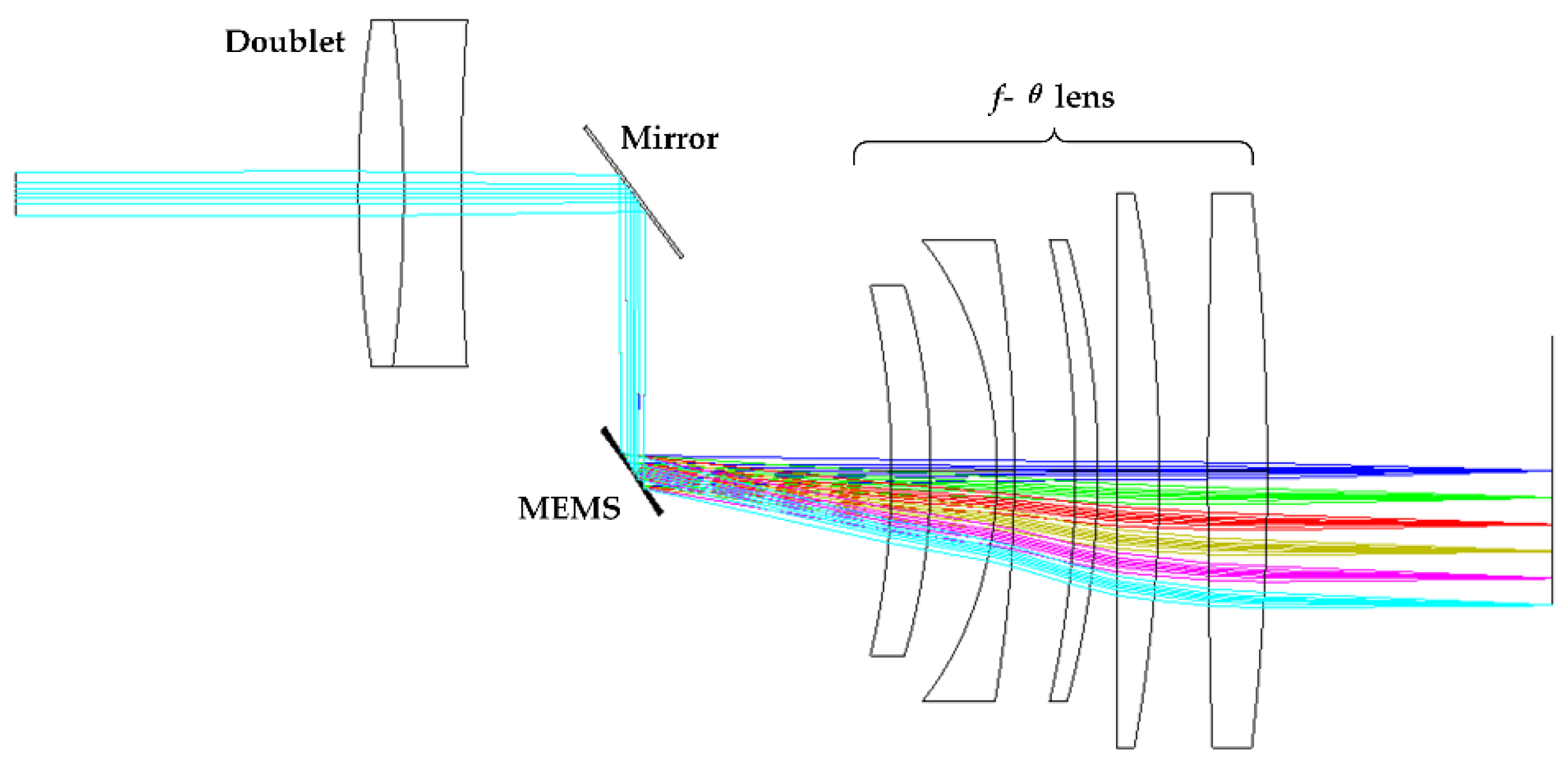
The f-θ lens should introduce barrel distortion, and because of its larger field of view, the off-axis aberrations should be corrected, such as astigmatism and field curvature. The lenses were optimized by The ZEMAX software using the optimization function, in which field curvature and distortion were optimized with the help of FCUR and DIST operands. The optimization function is set to the RMS spot radius, and FCUR and DIST operands are inserted and set to target 0 and weight 1. The two-dimensional structure of the cemented lens L0 and f-θ lens L1 designed in ZEMAX is shown in Figure 4. Scanning beams with different angles are in different colours, 0° in blue, 1° in green, 2° in red, 3° in gray, 4° in purple, and 5° in wathet. The f-θ lens is consist of 5 lenses with a focal length of 35 mm.
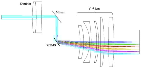
Figure 4.
Structure diagram of f-θ lens design by ZEMAX, 0° in blue, 1° in green, 2° in red, 3° in gray, 4° in purple, and 5° in wathet.
For the f-θ lens, it has a specific scanning speed, Equation (6) is derived for scanning time t:
where, is the rotation angular velocity of the MEMS mirror. As the image height h and the scanning angle γ of the f-θ lens satisfy the linear relationship, the linear control of the scanning speed can be achieved by controlling the scanning angle γ. If the MEMS mirror is deflected at a constant speed, the focused spot of the laser beam can be moved at a constant speed to realize a uniform scanning.
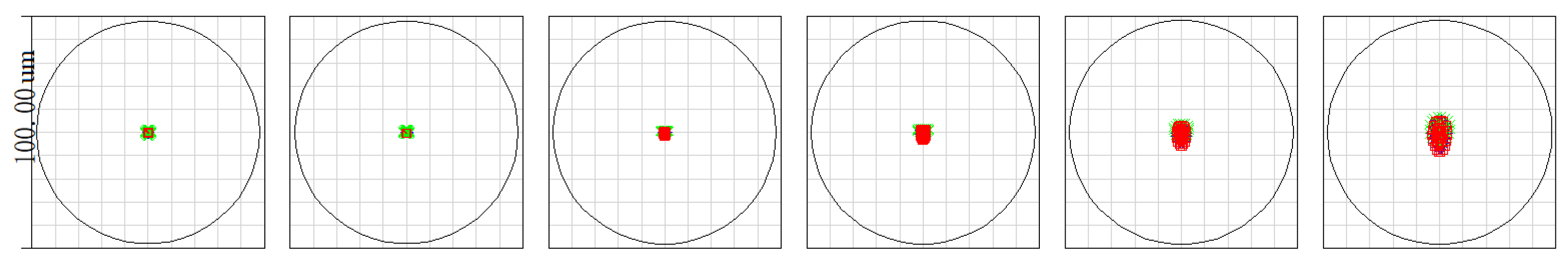
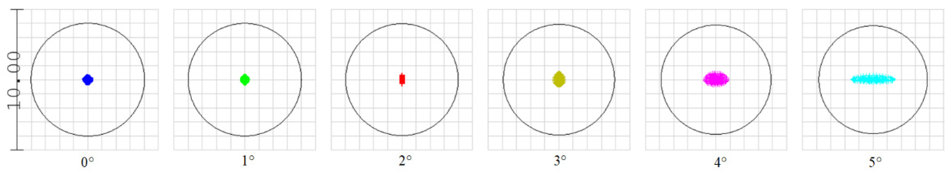
Set the tilt angles of the MEMS mirror in ZEMAX in multiple configurations to simulate its actual rotation. Due to the symmetry of the rotation angles, we only set 0°, 1°, 2°, 3°, 4° and 5°. When the mirror is not deflected (relative to the position 0°), the size of the diffuse spot is within 2 µm, then as the deflection angle increases to 1°, the diffuse spot is within 4 µm. The maximum deflection angle is 5°, and the diffuse spot less than 20 µm. The dispersion spot distribution at the optical system image plane is shown in Figure 5. Light in green, blue and red referring to the laser wavelength of 1520 nm, 1550 nm, and 1570 nm, respectively. The Airy disk radius is given by 1.22 times the wavelength times the F number of the beam, which in general depends upon field position and pupil orientation. If all the rays are well within the Airy disk, then the system is often said to be “diffraction limited”. From Figure 5, we can see that the light spots are all within the Airy disk, meeting the design requirements.
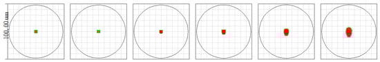
Figure 5.
Light spots with the rotation angles 0°, 1°, 2°, 3°, 4°, 5°, the circles are the Airy disks.
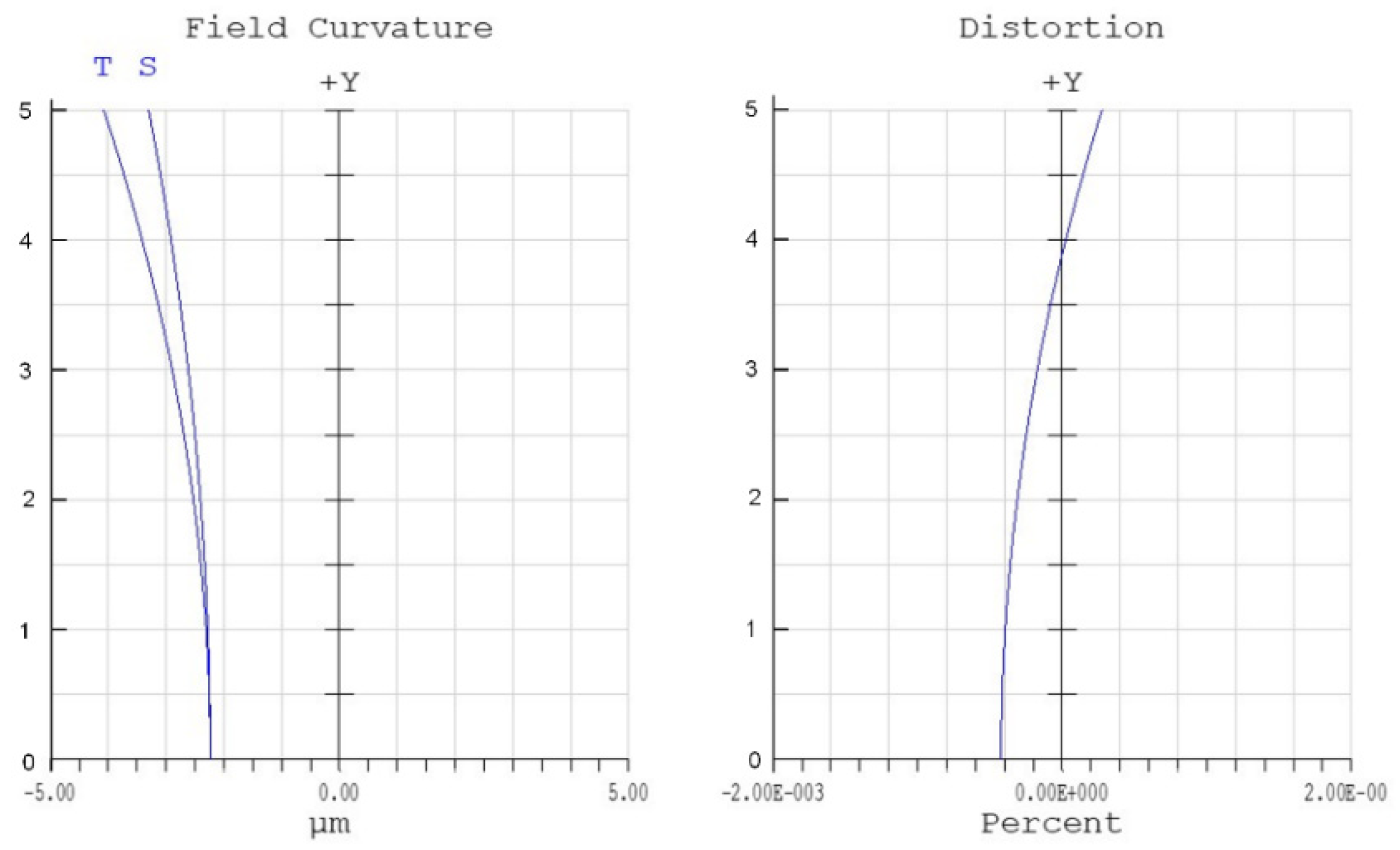
Figure 6 shows the field curvature and distortion diagram of the optimized f-θ lens. It can be seen that the relative distortion is less than 0.5%, which satisfies the design requirement. The linearity of the optimized f-θ lens system is very high.
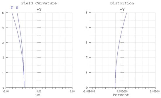
Figure 6.
Field curvature and distortion of f-θ lens.
The light beam from the collimating lens group should be parallel or approximately parallel light, which must ensure that the object focal plane of the collimating lens group coincides with the image focal plane of the f-θ lens. To obtain a field of view not less than ±25°, the focal length of the collimating lens group should be:
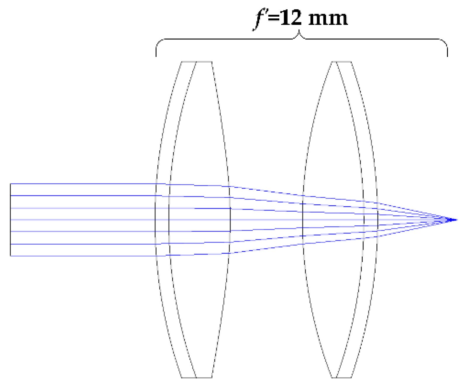
In order to extend the scan angle to a greater extent, the focal length of the collimating lens group is determined to be 12 mm. The collimating lens group is composed of two approximately symmetrical doublet lenses. Its two-dimensional structure is shown in Figure 7. This structure can not only correct coma and astigmatism, but also has a compact structure and small field curvature.
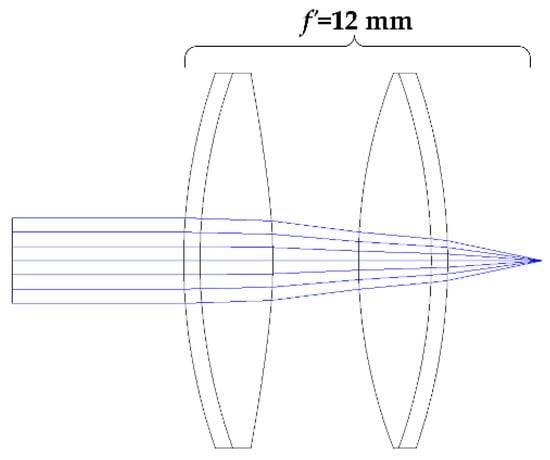
Figure 7.
Two-dimensional structure diagram of symmetrical cemented lens group.
Combining the doublet lens L0, f-θ lens L1, common mirror, MEMS mirror, and collimating lens group L2 to complete the overall system design. The three-dimensional structure of the large-angle MEMS scanning optical system is shown in Figure 8. The parameters related to the design are listed in Table 2.
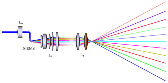
Figure 8.
Three-dimensional structure the large-angle MEMS scanning optical system.
Table 2.
Design parameters of MEMS scanning optical system.
4. Results and Discussion
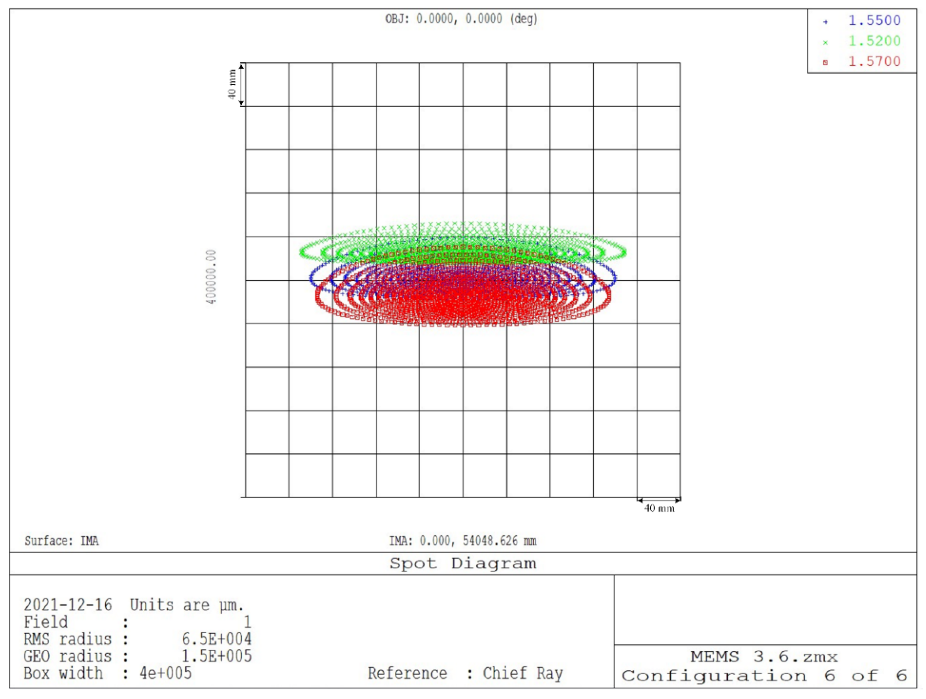
Setting the image distance to be 100 m, the point diagram distributions when the MEMS mirror rotates from 0° to 5° can be obtained as shown in Figure 9. The distribution of the spots are generally uniform and symmetrical, and are all within the Airy disks. When the MEMS mirror rotates from 0° to 5°, the corresponding spot RMS radius is maximum.
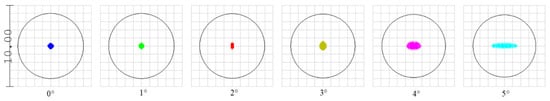
Figure 9.
The distributions of the point diagram with different angles, the circles are the Airy disks.
Set the laser wavelength to be 1520 nm, 1550 nm, and 1570 nm, Figure 10 shows the spots diagram at 5°. The spots all present symmetrical distributions, and the maximum RMS radius are all about 7 cm, which shows prefect achromatic property, suiting for FMCW application.
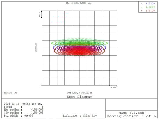
Figure 10.
Spot diagrams at 5°.
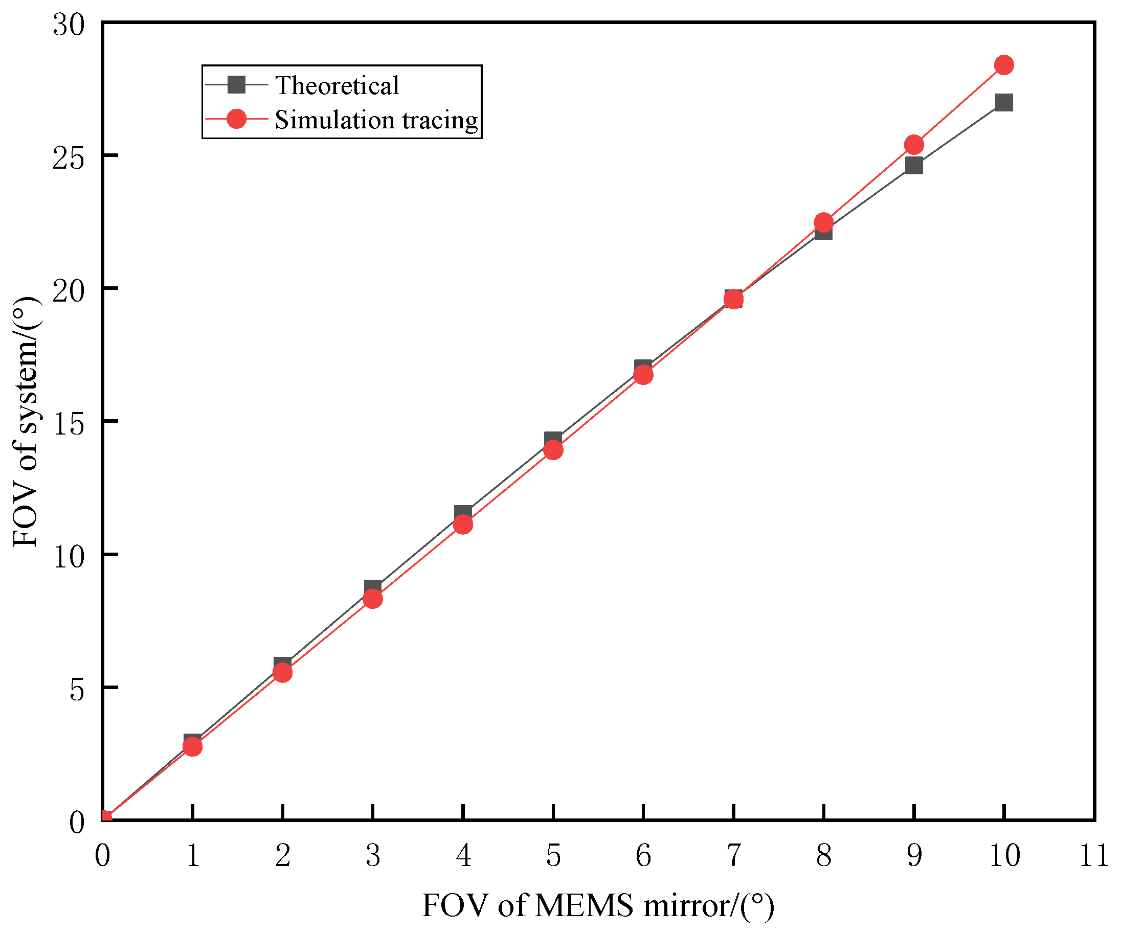
According to Equation (3), the theoretical FOV of the system with various angles can be calculated. The results obtained by ZEMAX ray tracing compared with that of the theoretical calculation are shown in Figure 11. The linear fitting shows that the FOV extending factor for the designed system is about 2.78, which is 2.56 according to the theoretical calculation. The difference between the simulation results and the theoretical calculation increases with the FOV, but the maximum error does not exceed 1.41°, showing excellent agreement. When the rotation angle of the MEMS mirror is 5°, the FOV of the system is the largest, which is 28.5 × 2 = 57°, and the maximum beam divergence is less than 0.5 mrad. The total length of the optical system is less than 12 cm. Compared with the traditional optical angle expansion system, our new design has distinct advantage in the FOV, which is usually less than 30° in real existing LIDAR system.
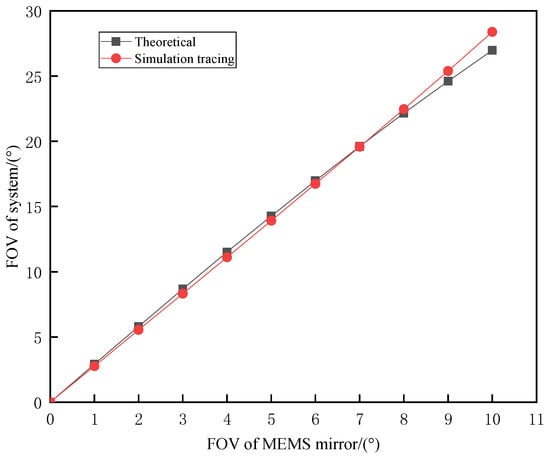
Figure 11.
Comparison of the FOV between theoretical calculation and simulation.
5. Conclusions
This work designed an angle extension optical system for a MEMS mirror whose mirror diameter is 5 mm and maximum mechanical rotation angle is ±5°. In this design an f-θ lens group is used for flat field scanning and a symmetrical cemented lens group is used for angle expansion. The design theory was derived in detail and a simulation was carried out by ZEMAX software. The designed system realized a scanning angle as large as 57° and is in good linear relation with the tilt angle of the MEMS mirror. At a target distance of 100 m, the maximum RMS radius of the light spot is only 7 cm, and the beam divergence angle is less than 0.5 mrad. The total length of the optical system is less than 12 cm, which is easy to install and greatly improves the space and volume for the whole system. This optical scanning system also shows significant application potentialities for other 3D imaging LIDARs.
Author Contributions
Conceptualization, Y.P. and M.Y.; methodology, Z.B.; software, K.Z. and Y.S.; validation, M.Y., Y.P. and Z.B.; formal analysis, Y.P.; investigation, K.Z. and Y.P.; resources, Z.B. and Y.P.; data curation, M.Y.; writing—original draft preparation, Y.P.; writing—review and editing, M.Y.; visualization, M.Y.; funding acquisition, Y.P. and Z.B. All authors have read and agreed to the published version of the manuscript.
Funding
This research was funded by the National Natural Science Foundation of China (grant number 61905063, and 61905061); the Natural Science Foundation of Hebei Province, China (grant number F2020202055).
Institutional Review Board Statement
Not applicable.
Informed Consent Statement
Not applicable.
Data Availability Statement
Not applicable.
Conflicts of Interest
The authors declare no conflict of interest.
References
- Azevedo, F.; Dias, A.; Almeida, J.; Oliveira, A.; Ferreira, A.; Santos, T.; Martins, A.; Silva, E. LiDAR-based real-time detection and modeling of power lines for unmanned aerial vehicles. Sensors 2019, 19, 1812. [Google Scholar] [CrossRef] [PubMed] [Green Version]
- Panjvani, K.; Dinh, A.V.; Wahid, K.A. LIDARPhone-a low-cost LIDAR-based 3d scanning system for leaf morphological trait extraction. Front. Plant Sci. 2019, 10, 00147. [Google Scholar] [CrossRef] [PubMed]
- Muftuoglu, I.K.; Bartsch, D.-U.; Barteselli, G.; Gaber, R.; Nezgoda, J.; Freeman, W.R. Visualization of macular pucker by multicolor scanning laser imaging. Retina 2018, 38, 352–358. [Google Scholar] [CrossRef] [PubMed]
- Weiss, U.; Biber, P. Plant detection and mapping for agricultural robots using a 3D LIDAR sensor. Robot. Auton. Syst. 2011, 59, 265–273. [Google Scholar] [CrossRef]
- Thakur, R. Scanning LIDAR in advanced driver assistance systems and beyond: Building a road map for next-generation LIDAR technology. IEEE Consum. Electron. Mag. 2016, 5, 48–54. [Google Scholar] [CrossRef]
- Gong, W.; Zhao, C.; Yu, H.; Chen, M.; Xu, W.; Han, S. Three-dimensional ghost imaging LIDAR via sparsity constraint. Sci. Rep. 2016, 6, 26133. [Google Scholar] [CrossRef] [Green Version]
- Bi, X. LiDAR Technology. In Environmental Perception Technology for Unmanned Systems; Springer: Singapore, 2021; pp. 67–103. [Google Scholar]
- Zhang, Y.; Shao, Z.F. Assessing of urban vegetation biomass in combination with LiDAR and high-resolution remote sensing images. Int. J. Remote Sens. 2021, 42, 964–985. [Google Scholar] [CrossRef]
- Wang, D.; Watkins, C.; Xie, H. MEMS mirrors for LiDAR: A review. Micromachines 2020, 11, 456. [Google Scholar] [CrossRef] [PubMed]
- Stettner, R. Compact 3D Flash LIDAR video cameras and applications. In Laser Radar Technology and Applications XV; SPIE: Bellingham, WA, USA, 2010; p. 851831. [Google Scholar]
- McManamon, P.F.; Banks, P.S.; Beck, J.D.; Fried, D.G.; Huntington, A.S.; Watson, E.A. Comparison of flash LIDAR detector options. Opt. Eng. 2017, 56, 031223. [Google Scholar] [CrossRef] [Green Version]
- Wang, Y.; Wu, M.C. An optical phased array for LIDAR. J. Phys. 2016, 772, 012004. [Google Scholar] [CrossRef]
- Hsu, C.-P.; Li, B.; Solano-Rivas, B.; Gohil, A.R.; Chan, P.H.; Moore, A.D.; Donzella, V. A review and perspective on optical phased array for automotive LiDAR. IEEE J. Sel. Top. Quantum Electron. 2021, 27, 1–16. [Google Scholar] [CrossRef]
- Xu, F.; Qiao, D.; Xia, C.; Song, X.; Zheng, W.; He, Y.; Fan, Q. A semi-coaxial MEMS LiDAR design with independently adjustable detection range and angular resolution. Sens. Actuators A Phys. 2021, 5, 112715. [Google Scholar] [CrossRef]
- Zhu, J.; Liu, X.; Shi, Q.; He, T.; Sun, Z.; Guo, X.; Liu, W.; Bin Sulaiman, O.; Dong, B.; Lee, C. Development trends and perspectives of future sensors and MEMS/NEMS. Micromachines 2020, 11, 7. [Google Scholar] [CrossRef] [PubMed] [Green Version]
- Yoo, H.W.; Druml, N.; Brunner, D.; Schwarzl, C.; Thurner, T.; Hennecke, M.; Schitter, G. MEMS-based LIDAR for autonomous driving. Elektrotechnik Und Inf. 2018, 135, 408–415. [Google Scholar] [CrossRef] [Green Version]
- Hu, Q.; Pedersen, C.; Rodrigo, P. Eye-safe diode laser Doppler LIDAR with a MEMS beam-scanner. Opt. Express 2016, 24, 1934–1942. [Google Scholar] [CrossRef] [PubMed] [Green Version]
- Takashima, Y.; Hellman, B.; Rodriguez, J.; Chen, G.; Smith, B.; Gin, A.; Espinoza, A.; Winkler, P.; Perl, C.; Luo, C.; et al. MEMS-based Imaging LIDAR. In Proceedings of the Optics and Photonics for Energy and the Environment, Singapore, 5–8 November 2018; p. ET4A.1. [Google Scholar]
- Niclass, C.; Ito, K.; Soga, M.; Matsubara, H.; Aoyagi, I.; Kato, S.; Kagami, M. Design and characterization of a 256 × 64-pixel single-photon imager in CMOS for a MEMS-based laser scanning time-of-flight sensor. Opt. Express 2012, 10, 11863–11881. [Google Scholar] [CrossRef] [PubMed]
- Lee, X.B.; Wang, C.H. Optical design for uniform scanning in MEMS-based 3D imaging LIDAR. Appl. Opt. 2015, 54, 2219–2223. [Google Scholar] [CrossRef] [PubMed]
- Lee, X.; Wang, C.; Luo, Z.; Li, S. Optical design of a new folding scanning system in MEMS-based LIDAR. Opt. Laser Technol. 2020, 125, 106013. [Google Scholar] [CrossRef]
- ZEMAX Development Corporation. Optical Design Program User’s Guide; ZEMAX: Kirkland, WA, USA, 2014. [Google Scholar]

Publisher’s Note: MDPI stays neutral with regard to jurisdictional claims in published maps and institutional affiliations. |
© 2022 by the authors. Licensee MDPI, Basel, Switzerland. This article is an open access article distributed under the terms and conditions of the Creative Commons Attribution (CC BY) license (https://creativecommons.org/licenses/by/4.0/).