Abstract
In recent years, CVD diamond-coated tungsten carbide (WC-Co) tools have been widely utilized due to their benefits in the machining of non-ferrous alloys and polymer composite materials, especially carbon-fiber-reinforced plastics (CFRPs). The reconditioning of such coated tools is economically attractive due to their high cost and short tool life. The decoating of the remaining diamond film from the used tools and the subsequent surface preparation by wet chemical pretreatment are essential steps for new CVD diamond film formation. Previously, it was shown that reactive ion beam etching (RIBE) could effectively remove CVD diamond films. However, some degree of WC-Co tool substrate damage is expected due to the high ion energy in RIBE and the chemical activity in wet etching. This study addresses the effects of RIBE decoating and surface pretreatment steps on WC-Co tools with a complex shape in terms of the ion-induced surface damage, geometry alteration, and adhesion of a subsequently re-applied CVD diamond film. Moreover, the cutting performance of the tools subjected to the RIBE decoating and repeated film deposition was studied via CFRP cutting tests. It has been shown that the RIBE decoated and recoated tools had a high level of cutting performance comparable to the new tools.
1. Introduction
It is well-known that the application of carbon-fiber-reinforced plastics (CFRPs) increases year by year in a wide range of industries, such as aircraft and automobiles. However, abrasion due to hard carbon fibers in CFRPs always leads to severe tool wear and, consequently, short tool life. Furthermore, when cutting tool conditions deteriorate due to wear and tear, the CFRP workpiece tends to show material-specific defects, such as delamination, burrs, and tearing of fibers. A well-known method of the tool life extension consists in the chemical vapor deposition (CVD) of polycrystalline diamond films on tungsten carbide (WC-Co) cutting tools [1,2,3].
Moreover, studies reported that the utilization of special shape-designed WC-Co tools with CVD diamond coatings benefits CFRP machining, resulting in less burr formation and delamination effects [4,5,6]. Further, tool wear resistance can be improved by doping CVD diamonds with minute amounts of boron. The resulting boron-doped micro-crystalline diamond (B-MCD) film has shown excellent results in CFRP machining in our previous study [7]. On the other hand, such B-MCD-coated WC-Co tools with complicated shapes have a higher cost than conventional tools. Therefore, an effective method of the tool life extension is of great interest.
Cutting tool reconditioning is one of the most efficient cost-saving strategies in the manufacturing industry [8]. For instance, Astakhov reported that drills could be reconditioned and reused up to 10 times, thus significantly reducing costs and tool material wasting.
Conventionally, reconditioning methods include sequential procedures, such as coating removal, tool regrinding, and film deposition [9]. Electrochemical etching (ECE) is commonly used for the decoating of metal-based composite films (e.g., TiN, TiAlN, TiAlCrN, and CrN) [10]. However, the ECE is not effective for the stripping of diamonds due to its high chemical stability.
The decoating of CVD diamond films by oxygen plasma has been studied by Yunata et al. [11,12] and Liu et al. [13]. However, these bulk plasma-based approaches have uniformity and scalability issues. A practically important method of CVD diamond decoating has been developed by Remnev [14]. The method consists in the reactive ion beam etching (RIBE) of a CVD diamond film with multiple closed electron drift ion sources (CDIS). The method has been shown to be able to strip both CVD diamonds and metal-based composite films from cutting tools with a complex geometry. On the other hand, the cutting performance of RIBE-reconditioned tools has not been studied. Indeed, energetic particle bombardment may alter the surface properties and the micro-geometry of the tools, negatively affecting the cutting performance of the reconditioned tools.
In order to reuse the cutting tools after the decoating, the CVD diamond film must be re-applied, so the tools recover its mechanical properties. Typically, several extra steps are required prior to the film deposition: cleaning, Co wet-chemical etching (WCE) from the surface, and seeding [15]. The WCE is the most aggressive among these surface preparation steps and may negatively impact the WC-Co tool integrity. Therefore, the combined effects of RIBE decoating and WCE on various important tool properties have been investigated in the present work. The surface morphology, cutting edge geometry, B-MCD film adhesion and structure, and finally cutting performance were evaluated and discussed from the standpoint of the reconditioning approach.
2. Materials and Methods
2.1. Experimental Procedures
In this study, as shown in Figure 1, the substrate pretreatment (WCE), B-MCD deposition (CVD), CFRP cutting (CT), and film decoating (RIBE) were conducted repeatedly on one-shot cemented carbide drills in order to emulate the practically viable tool life cycle (TLC). The tool substrate and the film properties were investigated at each step using a combination of surface characterization techniques such as scanning electron microscopy (SEM), confocal scanning laser microscopy (CSLM), and Raman spectroscopy. Moreover, the cutting performance was evaluated during the CT through flank wear and CFRP hole quality assessment. The evaluation was performed for three consecutive TLCs, including the TLC0 (WCE0, CVD0, and CT0)—a newly deposited tool, the TLC1 (RIBE1, WCE1, CVD1, and CT1)—a first-time reconditioned tool, and the TLC2 (RIBE2, WCE2, CVD2, and CT2)—a second-time reconditioned tool.
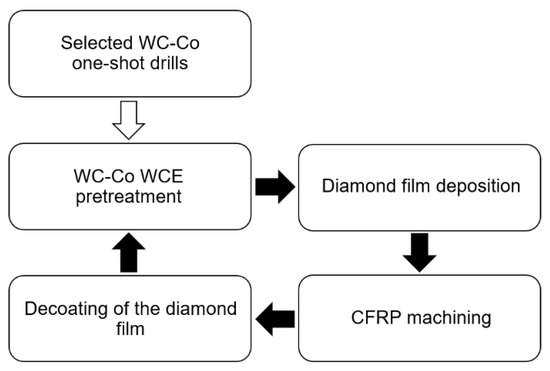
Figure 1.
Tool life with multiple reconditioning cycles.
The CT0, CT1, and CT2 machining were interrupted prior to the major tool damage occurrence in order to limit the wear to the B-MCD film and not the WC-Co substrate. Due to this tool-saving approach, no tool regrinding was necessary.
2.2. Cutting Tools
One-shot WC-Co drills with a specific geometry optimized for CFRP materials were selected for the experiment. The structure of the drill bit is presented in Figure 2. The drill with a nominal diameter of 6.36 mm had two straight flutes with a tip point angle of 120° and two curve-shaped edges, namely, primary and secondary cutting edges, joined by a rounded corner. A straight tertiary cutting edge (Figure 2b) formed a reamer part of the tool, aimed at the smoothing of the drill holes and providing the hole diameter close to the nominal. Such an innovative drill geometry was described in a corresponding patent [16]. Other drill dimensions were as follows: the total length was 88 mm, the cutting edge length was 40 mm, and the shank diameter was 9 mm. All drill substrates were made of K01 graded tungsten carbide with cobalt (WC-6 wt. % Co). This material is commonly used to manufacture complicated-cutting-shape tools and can be coated with CVD diamonds. The total of three drill bits were investigated with the reconditioning steps.
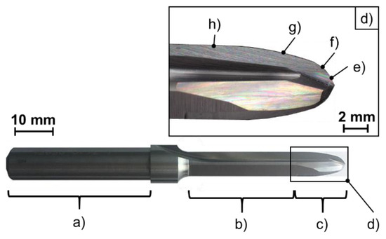
Figure 2.
One-shot WC-Co drill utilized in the current study: (a) drill shank; (b) reamer cutting portion; (c) cutting edge portion; (d) magnified view of the drill cutting edge portion; (e) primary cutting edge; (f) rounded corner; (g) secondary cutting edge; (h) tertiary cutting edge.
2.3. Substrate Preparation and Deposition of the Diamond Coating
This study utilized B-MCD coating, which has shown excellent performance in CFRP machining.
Prior to the diamond film deposition, the drills were chemically pretreated. The conventionally used WCE method, described by several authors [15,17], was applied for the selected substrates and included treatment steps with the Murakami reagent and followed a nitric acid solution. All chemical etching steps were performed by immersing the tool substrates into an ultrasonic bath with the corresponding chemicals. Afterward, the pretreated tools were seeded ultrasonically by a purified water suspension with a nanodiamond having a 4 nm average particle size.
A B-MCD film was deposited on the substrates using the hot-filament chemical vapor deposition (HFCVD) method in an industrial hot-filament reactor (ShinMaywa Industries, Hyogo, Japan). Common deposition parameters are shown in Table 1. A mixture of CH4 and H2 was utilized as a precursor gas in the deposition step and nucleation deposition process stages. The boron incorporation was carried out by evaporating a mixture of trimethoxyborane ((CH3O)3B) with acetone. The HFCVD setup and process details can be found in our previous work [18].

Table 1.
Deposition process parameters.
As a result, the B-MCD coating with a thickness of about 10 µm ± 1 µm was deposited on the tested drill. After each process stage, the deposited diamond film and chemically and/or ion-etched substrate surface were examined in terms of the surface morphology by a scanning electron microscope (SEM JSM5510, JEOL, Tokyo, Japan). In addition, the surface roughness evaluations for all process stages were conducted with a laser microscope (OLS4100, Olympus, Tokyo, Japan). In the assessment of the adhesion strength between the deposited coating and the WC-Co substrate, indentation tests were carried out (Rockwell hardness testing machine ARK-600, Mitutoyo, Kanagawa, Japan).
2.4. Decoating by the RIBE
Diamond-film RIBE decoating was performed with a commercial ion etching system (IE400, ShinMaywa Industries, Hyogo, Japan). The experimental setup is shown in Figure 3. The diamond etching was achieved through oxygen ion beams generated with CDIS. The CDIS beam generation relies on the crossed electric and magnetic field discharge, where electrons are trapped in a circular region near the magnetic trap while ions are freely accelerated by the electrical field. More details of the CDIS principle and structure can be found elsewhere [19].
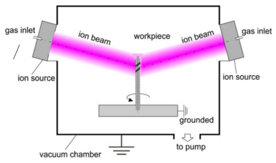
Figure 3.
Reactive ion beam etching (RIBE) experimental setup [14].
The tools for decoating were placed in a vacuum chamber and exposed to a CDIS concentric array. The beam size of CDIS was ~100 mm in diameter and covered the whole coated length of the processed tools, so that the whole coating was etched with a good uniformity along the vertical axis. In addition, the tools were rotated planetary in order to provide an even ion/radical flux exposure in the horizontal plane, which was previously shown to result in a good etching uniformity inside the flutes [20].
Pure oxygen was used as a beam-forming gas. The accelerating voltage was set to 4.0 kV, which generated a discharge current of ~100 mA at a 0.3 Pa pressure.
The RIBE rate was evaluated in a previous work and was about 1.7 µm/h for the microcrystalline diamond film. Wherever the ion beam contacts with the uncoated tool parts, the WC-Co sputtering also took place but with a much slower rate due to the primarily chemical nature of the process [14]. The applied tools were etched for 6 h in the same batch. The temperature during the etching did not exceed 300 °C.
2.5. Cutting Tests
In this study, the cutting performances of new and reconditioned drills were evaluated by drilling a series of consecutive holes in a workpiece. CFRPs laminated with a thickness of 14 mm and dimensions of 250 mm × 100 mm were used as the workpiece. Each workpiece consisted of 72 unidirectional layers of prepreg (T800S series, TORAY, Osaka, Japan) with a quasi-isotropic laminate lay-up. The carbon fiber volume ratio was about 60%.
A vertical milling center OKUMA MD-45VA was utilized to perform the drilling tests. The experimental setup is shown in Figure 4. The cutting parameters were as follows: the drill rotation n was 2700 rpm, the cutting speed V was 53.9 m/min, and the feed rate ƒ was 0.1 mm/rev, which were kept constant. No coolant was applied during the tests. The number of drilled holes was limited to below 200 in order to avoid the drill substrate wear and the necessity of tool regrinding. A drill flank wear was measured after each 20 holes using a digital microscope (VHX-1000SP, Keyence, Osaka, Japan). After drilling 200 holes, the drills were checked for the damage to cutting edges, such as cutting edge chipping or a fracture via SEM.
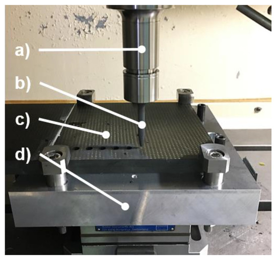
Figure 4.
Experimental setup for cutting tests ((a), machine; (b), tested drill; (c), carbon-fiber-reinforced plastics (CFRPs) workpiece; (d), fixture).
3. Results and Discussion
3.1. Tool Surface Evaluation
Figure 5 displays the substrate surface morphologies obtained by SEM for different stages of the experiment, while Figure 6 shows the resulting surface roughness data of the stages. Surface texture parameter Sa, as an arithmetical mean height, based on ISO 25178—“Surface Texture”, was recorded and averaged from multi-point measurements on the flank surfaces of the drills. The scan size was determined by the optical magnification of the system (100×) in a resulting surface area of 129 µm × 129 µm with a profile Gaussian filter λc of 8 µm.
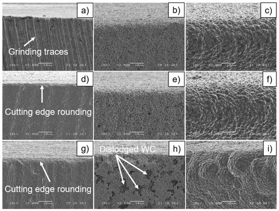
Figure 5.
Morphologies of the drill flank surface, observed at 6 mm from the drill tip: (a) original, as grinded; (b) wet-chemical etching 0 (WCE0) of the new drill (TLC0); (c) chemical vapor deposition 0 (CVD0) of the TLC0; (d) reactive ion beam etching 1 (RIBE1) of the 1st-time reconditioned drill (TLC1); (e) WCE1 of the TLC1; (f) CVD1 of the TLC1; (g) RIBE2 of the 2nd-time reconditioned drill (TLC2); (h) WCE2 of the TLC2; (i) CVD2 of the TLC2.
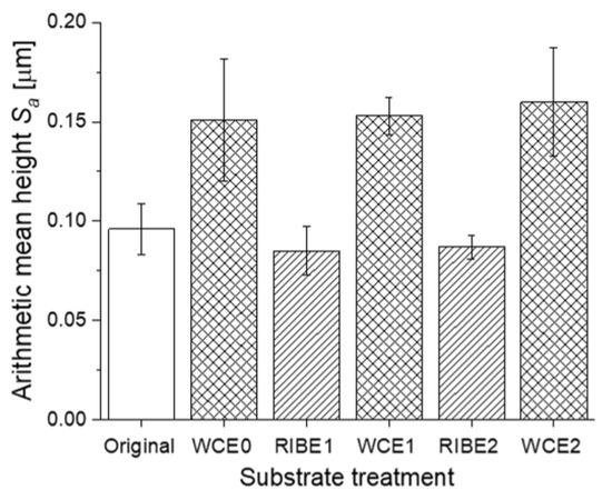
Figure 6.
Substrate roughness characteristics by the arithmetical mean height (Sa) of the surface texture.
The original drill substrate, as shown in Figure 5a, represented the as-ground surface depicting the directional marks left by the grinding process on the surface of the tool, which also provided a non-uniform texture in terms of the distribution of the WC grains and the Co binder due to the amount of surface damage after the grinding process [21]. These feed marks display an average surface texture roughness of Sa = 0.096 µm.
The surface morphology after the WCE0 process, as shown in Figure 5b, revealed a uniform surface with Sa value of 0.151 µm and some directional surface features. The increase in the roughness after the process is attributed to the WCE, which attacked the WC grains and oxidized the cobalt binder to soluble Co compounds removed during the procedure under applied ultra-sonication [15]. Such a washing action may dislodge weakly bonded WC grains from the surface and create some porous surface textures. Further, Figure 5e shows a uniform surface with a roughness Sa parameter of 0.153 µm, generated after the WCE1 process of the 1st reconditioning cycle. However, the surface, produced by the WCE2 process of the 2nd reconditioning cycle, had a rougher texture with Sa of 0.160 µm and pitted areas, as shown in Figure 5h. It is possible to propose that an accumulative effect of removing the binder phase in WCE stages led to the formation of randomly distributed, Co-free areas of the substrate with a depth deeper than the WC average grain size. Then, the weakly bonded carbide grains were dislodged by cavitation during an ultrasonic washing action after the chemical etching. As a result, the non-uniform-sized pitted areas appeared on the substrate surfaces after the WCE2 process. Thus, three repeated chemical etching processes over-treated the surface and provided porous textures due to the loss of WC grains and the Co depletion.
On the other hand, the RIBE process generated a rather smooth and uniform surface after all decoating cycles. Figure 5d,g shows the morphologies of ion-etched surfaces after the 1st and 2nd decoating processes of the tool reconditioning, respectively. The roughness values of the etched surfaces consisted of Sa of 0.085 µm and 0.087 µm after the 1st (RIBE1) and 2nd (RIBE2) decoatings, respectively. The observed effect of the partial surface integrity regeneration via RIBE can be attributed to the physical sputter etching of the damaged the WC-Co layer by energetic oxygen ions down to the pristine WC-Co.
The surface morphologies of the deposited diamond coatings are shown in Figure 5. The diamond surfaces, displayed in Figure 5c,f corresponding to the TLC0 and the TLC1, respectively, showed similar continuous, well-defined faceted textures of randomly oriented diamond grains with an average size of approximately 3 µm. Contrary, as shown in Figure 5i, the diamond coating deposited on the TLC2 consisted of a combination of small faceted grains in globular agglomerated textures distributed mainly along the cutting edges.
This difference between the observed diamond films may be attributed to a high diamond nucleation density as the result of the rougher surface due to a huge amount of pits at the surface, as shown in Figure 5h. As the depth of pits increased with the surface roughness, more diamond particles were embedded within the rough surfaces. This enhanced the nucleation of the diamond crystal and its growth behavior. Therefore, it can be proposed that the WCE2 process detrimentally reconstructed the surfaces, especially in the cutting edge areas, because over-treated surfaces induced the formation of non-uniform diamond films. A similar correlation between the substrate surface roughness and the diamond film morphology has been reported by Gomez et al. [17]. In their study, a diamond coating with a combination of small crystal facets in ball-like agglomerates was obtained on rougher samples compared between all pretreated samples.
In order to assess the quality of the deposited diamond coatings, Raman spectroscopy was employed. The Raman spectra of the diamond coatings are displayed in Figure 7, adopting the Raman microscope (RAMAN-11, Nanophoton, Osaka, Japan) and a laser with a visible excitation wavelength of 532 nm.
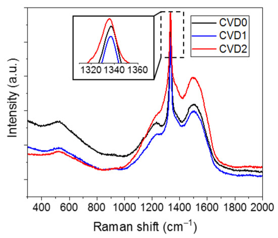
Figure 7.
Raman spectra of the CVD0, CVD1, and CVD2 coatings, using a green (λ = 532 nm) excitation.
It was found that the peak around 1332 cm−1, indicative of the sp3 bonding of the diamond, can be visible evidently for all the films [22]. The Raman bands were present as 1337.27 cm−1, 1337.28 cm−1, and 1335.38 cm−1 in CVD0, CVD1, and CVD2 films deposited on the TLC0, the TLC1, and the TLC2, respectively. The wavelengths of these peaks shifted from the value of the natural diamond (1332.4 cm−1), indicating the residual stress in the diamond films.
From the frequency υ of the diamond band, the residual stresses in the diamond coatings could be estimated using the method described by Ralchenko et al. in their research [23]:
where υ0 is 1332.4 cm−1 and the negative corresponds to the compressive stress.
σ (GPa) = −0.567 × (υ − υ0),
According to this method, the residual stresses of the CVD0, CVD1, and CVD2 films were calculated as −2.761 GPa, −2.766 GPa, and −1.689 GPa, respectively. The CVD2 film had the lowest compressive stress value between the compared films, possibly due to the finer B-MCD structure and intergranular relaxation.
Furthermore, several visible peaks, characteristic of a diamond coating, can be identified as well. All presented Raman spectra showed two peaks located around 520 cm−1 and 1250 cm−1, which is associated with the actual boron incorporation in the lattice [24]. In addition, the broad dominated peaks located around 1500 cm−1 for the CVD0, CVD1, and CVD2 films revealed the presence of sp2 graphite (G-peak) phases [22]. The growth G-peak intensity of CVD2 can be associated with an increased non-diamond phase value due to reduced diamond grains.
3.2. Adhesion Evaluation
In order to evaluate the adhesive strength between the deposited diamond coatings and the drill’s substrate after the initial and reconditioning cycles, indentation tests were carried out using a Rockwell hardness testing machine with a diamond indenter, which had a conical angle of 120° and a radius of curvature at the tip 0.2 mm. Each diamond-coated drill was tested under a load of 980.7 N. Figure 8 shows the SEM images of the surface morphologies of the coated drills after the indentation tests. For the TLC0 and the TLC1, as shown in Figure 8a,b, respectively, cracks of the diamond coatings around the indenter trace were observed. On the other hand, Figure 8c reveals the peeling of the diamond film of the TLC2 after indentation. A magnified SEM image of the film-peeled area, presented in Figure 8d, showed the substrate voids partially filled with the diamond material. The existence of the voids decreased the mechanical strength of the interface and created stress concentration regions. Thus, the adhesion force was significantly reduced.
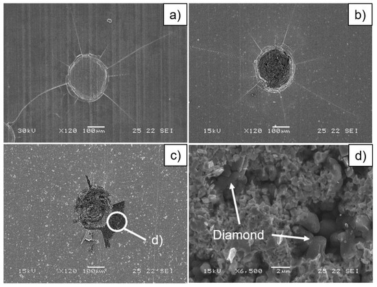
Figure 8.
Scanning electron microscopy (SEM) images of indentation morphologies, obtained by a Rockwell testing machine with a load of 980.7 N on the TLC0 (a), the TLC1 (b), and the TLC2 (c,d).
The voids originated from the WCE2 step, as shown in Figure 5h. Evidently, the diamond growth started inside the voids but did not completely fill them out before the continuous film coalesced and incapsulated the voids, blocking the gas-phase C transport and deposition in those areas. The findings suggested that the WCE2 and further step conditions should be fine-tuned in order to prevent the formation of excessively large craters and subsequent film voids. Another possible way is to apply the selective seeding process that stimulates an in-depth diamond growth, as has been reported by Linnik et al. [25].
3.3. Cutting Edge Rounding Evaluation
In this study, the cutting edge rounding (CER) value was employed for the evaluation changing of the geometric shapes of drill cutting edges through the initial and reconditioning cycles of the experiments. A number of references reported the correlation between CER values and cutting forces, machined material delamination, etc. [26,27,28]. In addition, the CER parameter is frequently used as a criterion of tool wear, especially for non-coated WC-Co-based tools [29].
The CER values were measured on the tool substrates in two cutting edge places based on the applied one-shot drill shape.
The first measurement position was determinate on the secondary cutting edge at 6 mm from the drill tip, and the drill cutting edge profile was characterized. It should be noted that the same position was used for the flank wear evaluation, described in the following section. The second measurement position, associated with the reamer geometry, was on the tertiary cutting edge at 11 mm from the tip. Figure 9 shows the cutting edge profiles for both measurement positions described above carried out by a laser microscope (OLS4100, Olympus, Tokyo, Japan). First, the three-dimensional (3D) images of the cutting edge in the measurement positions were obtained from a surface area of 129 µm × 129 µm by an optical magnification of the system (100×). Then average values in this area for the edge radius were determined.
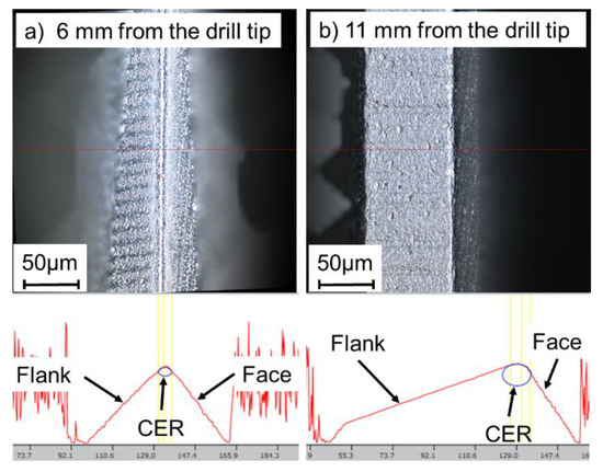
Figure 9.
Measurement results of the cutting edge rounding (CER).
Figure 10 and Figure 11 reveal the evolution of the CER values measured after the substrate treatment procedures. As shown in Figure 10, each pretreatment before diamond deposition led to increasing CER values. Because the chemical etching process accompanied the Co binder’s removal and loss of tungsten carbide grains, influencing the tool size and shape. On the contrary, the cutting edge sharpening effect was observed after the decoating stages. Although the film removal was not released uniformly for a complicated shape of the drill and the sputtering of the substrate occurred as well, the CER values decreased by approximately 0.5 µm every time for both the cutting edge geometries. The observed effect of micro-sharpening has been previously reported for medical needles exposed to ion beam irradiation with similar process parameters in the present study [30]. The mechanism consists in the incident angle-dependent sputtering yield, which drives the shape modification towards sharper edges in certain angle ranges and ion energies. For the cutting tools, the ion-induced sharpening of the edges may be beneficial from the standpoint of the cutting force reduction.
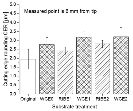
Figure 10.
Change of the CER (6 mm measured point).
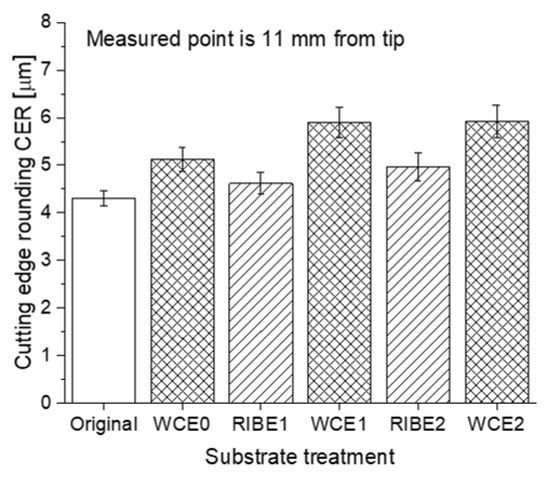
Figure 11.
Change of the CER (11 mm measured point).
3.4. Drill Flank Wear Evaluation
In the cutting tests, tool wear was evaluated as the maximum flank wear land width (VBmax) as a function of the drilled hole number, as shown in Figure 12. Based on trial cutting test results, the VBmax was always determined on the secondary cutting edge at 6 mm from the drill tip, which was placed close to the rounded corner connecting the secondary and the tertiary edges. Since there was a gradient in the tool wear from the corner of the drill cutting edge to the center, the area of the second cutting edge indicated above kept higher values of the flank wear measured in preliminary cutting tests compared to other areas of the drill edges. The results, shown in Figure 12, indicated that the evolution of the VBmax values for the TLC0, the TLC1, and the TLC2 can be divided into two regions. The first region was the primary wear taking place, when ~40 holes were drilled. The second region was the region of steady-state wear observed between ~40 and 200 drilled holes. This was a normal operating region for the cutting tool. Some minor differences between the flank wear values were observed for the new and reconditioned diamond-coated drills. The abrasion of rough grains of the B-MCD film occurred with a fast increasing trend of the flank wear value, until 40 holes were drilled. Then, the smoothed diamond film led to the gradually increased wear, until 200 holes were drilled. However, the flank wear progress of the TLC2 showed a dramatically increasing trend after drilling 180 holes, which is typical for an accelerated wear region with the vanishing of the diamond film and the progressive substrate wear.
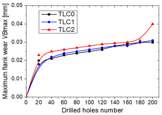
Figure 12.
Variations of the maximum flank wear as a function of the drilled holes number.
Figure 13 shows the wear morphologies of the tested drills after drilling 200 holes. For the TLC0, only the abrasion wear of the diamond film along the cutting edge was observed clearly, as shown in Figure 13b,c. The TLC1 images (Figure 13e,f) showed the worn diamond film with localized film flaked areas, while the film detachments and the worn areas of the substrate were observed for the TLC2, as shown in Figure 13i.
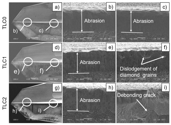
Figure 13.
SEM images of the TLC0 (a–c), the TLC1 (d–f), and the TLC2 (g–i) after drilling 200 holes.
During drilling, the cutting force instability produced by the altered orientation in the CFRP layers resulted in an intermittent cutting, which may have led to fatigue failure in the coating layer. In addition, a contact area was enhanced between the cutting edge and the machined surface due to the wear progress, which resulted in continuous or intermittent impacts and fluctuations of the cutting forces, which may induce additional shear stress and cracks beneath the film surface. Such a cutting force combined effects, and the propagation of cracks along the film–substrate interface with the film detachment can occur. Therefore, the film detachment that occurred on the TLC2 could be attributed to the deteriorated adhesion between the diamond film and the WC-Co substrate by the 2nd-time reconditioning procedures, as discussed in the previous sections.
On the other hand, the drill tip areas of the TLC1 and the TLC2, as shown in Figure 13e,h, had abrasion only, which can be explained as influencing the load of the thrust force mainly.
Despite that diamond film detachment occurred on the TLC2, it can be considered that all reconditioned drills showed flank wear values comparable with the new drill.
3.5. Hole Quality Evaluation
Drilling CFRPs can induce damage surrounding the hole circumferences or inside the hole wall surfaces, including burrs, tearing, delamination, and matrix thermal damage [31]. These defects affect the quality of drilled holes and may risk rejection of final composite structures. Moreover, delamination during drilling CFRP components has been recognized as the main irreparable failure that frequently occurs at the hole entry and exit sides [32]. It is defined as the separation of adjacent composite plies and is characterized by interlaminar cracks in the material. The damage that occurs on the hole entrance is usually called peel-up delamination, while the hole exit damage is called push-out delamination. Peel-up delamination is a consequence of the cutting force pushing the separated and cut materials to the tool flute surface. In comparison, push-out delamination is caused by the thrust force bending the residual laminas shortly before the exit.
In this study, both types of CFRP delamination induced by the new and reconditioned drills were evaluated through the frequently used method proposed by Chen [33]. Delamination factor Fd is defined as the ratio of the maximum diameter of a damaged zone (Dmax, mm) to the nominal diameter of the hole (D, mm), and two circles are concentric. Then, the value of Fd can be expressed as:
Fd = Dmax/D.
The maximal diameter of the damaged zone around each hole was measured using a digital microscope (VHX-1000SP, Keyence, Osaka, Japan). For both delamination cases, as shown in Figure 14 and Figure 15, the curves of the delamination induced by the TLC0 and the TLC1 showed similar behaviors and correlated with the drill flank wear data. The tool wear evolution generated an increase in the torque and the thrust force, which led to the CFRP delamination appearance. Indeed, when the cutting forces value exceeded the interlaminar fracture toughness of the laminates, delamination occurred.
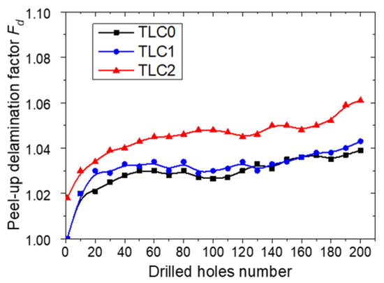
Figure 14.
Variations of the delamination factor on the entry hole side as a function of the drilled holes number.
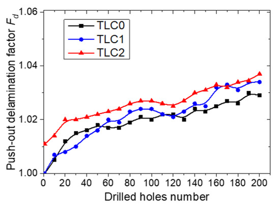
Figure 15.
Variations of the delamination factor on the exit hole side as a function of the drilled holes number.
Meanwhile, the TLC2 induced some delamination since the first hole was drilled, as shown in Figure 14 and Figure 15. Further, the peel-up and push-out delamination curves showed gradually increased trends. Such curves behaviors can be explained as the effect of the non-uniform globular formation of the diamond film along the drill cutting edges. These formations generated varied edge geometries with different cutting angles that may lead to an unstable cutting process through the vibration with changing of the cutting forces. Subsequently, abrasion led to a smoothing of the diamond film, and the delamination curves correlated with the corresponding flank wear curve.
Figure 16 and Figure 17 show images of holes entries and exits for the first and final holes drilled by the tested drills with the corresponding delamination factor values. The images presented the minor delamination of the last holes and the absence of cutting-induced breakout damages, such as burrs and splintering.
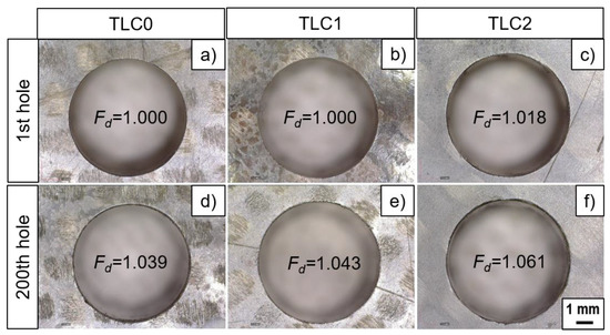
Figure 16.
Images of the 1st and 200th CFRP hole entry sides made by the TLC0 (a,d), made by the TLC1 (b,e), and made by the TLC2 (c,f).
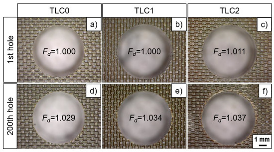
Figure 17.
Images of 1st and 200th CFRP hole exit sides made by the TLC0 (a,d), made by the TLC1 (b,e), and made by the TLC2 (c,f).
Regarding the holes’ size comparison, the drilled hole sizes were measured with a gauge plug having a nominal diameter of 6.36 mm. The gauge passed through all holes drilled by new and all reconditioned drills. Therefore, it is possible to conclude that the tested drills kept the drilled holes in the tolerance zone with the required size.
Based on the above evaluations, it was suggested that holes produced by the TLC0, the TLC1, and the TLC2 had comparable qualities in terms of the hole size and the delamination.
4. Conclusions
In this study, one-shot diamond-coated drills have been reconditioned two times without the drill regrinding between reconditioning processes. Then, the cutting performance of the reconditioned diamond-coated drills in drilling CFRP laminates was experimentally investigated and compared with the new diamond-coated drills. The main conclusions obtained were as follows:
(1) The RIBE decoating has demonstrated an insignificant influence on the WC-Co while completely removing a B-MCD film.
(2) The repeated substrate WCE pretreatment process resulted in increased crater formation in the WC-Co and should be tailored for the tool reconditioning in order to maintain the adhesion force of the B-MCD and maintain the WC-Co surface region mechanical robustness.
(3) The cutting performance of the reconditioned drills was confirmed through the drilling tests. All produced CFRP holes kept the required hole size and showed the absence of critical delamination and burrs. Moreover, even the two-time reconditioned drills showed the cutting performance results regarding the flank wear and the hole quality comparable with the new drills.
(4) The discussed RIBE-based reconditioning approach to the B-MCD-coated cutting tools may give significant advantages in CFRP machining in terms of the cost and the material savings and may facilitate a transition towards an eco-friendly circular economy.
Author Contributions
Conceptualization, A.S. and A.R.; methodology, A.S. and A.R.; investigation, A.S. and A.R.; writing of the original draft preparation, A.S. and A.R.; writing of review and editing, A.S., A.R., and A.O.; supervision, A.O. All authors have read and agreed to the published version of the manuscript.
Funding
This research received no external funding.
Institutional Review Board Statement
Not applicable.
Informed Consent Statement
Not applicable.
Data Availability Statement
The data presented in this study are available on request from the corresponding author. The data are not publicly available due to privacy restrictions.
Conflicts of Interest
The authors declare no conflict of interest.
Notation List
| B-MCD | boron-doped microcrystalline diamond; |
| CVD0–CVD | diamond film, deposited on the new tool; |
| CVD1–CVD | diamond film, deposited in the first reconditioning cycle; |
| CVD2–CVD | diamond film, deposited in the second reconditioning cycle; |
| RIBE1 | reactive ion beam etching of the diamond-coated drill for the first time; |
| RIBE2 | reactive ion beam etching of the diamond-coated drill for the second time; |
| TLC0 | newly deposited tool; |
| TLC1 | first-time reconditioned tool; |
| TLC2 | second-time reconditioned tool; |
| WCE0 | wet chemical etching of the new WC-Co substrate; |
| WCE1 | wet chemical etching of the WC-Co substrate in the first reconditioning cycle; |
| WCE2 | wet chemical etching of the WC-Co substrate in the second reconditioning cycle. |
References
- Rajakumar, I.P.T.; Hariharan, P.; Vijayraghavan, L. Drilling of carbon fibre reinforced plastic (CFRP) composites—A review. Int. J. Mater. Prod. Technol. 2012, 43, 43–67. [Google Scholar] [CrossRef]
- Liu, D.; Tang, Y.; Cong, W.L. A review of mechanical drilling for composite laminates. Compos. Struct. 2012, 94, 1265–1279. [Google Scholar] [CrossRef]
- Che, D.; Saxena, I.; Han, P.; Guo, P.; Ehmann, K.F. Machining of carbon fiber reinforced plastics/polymers: A literature review. J. Manuf. Sci. Eng. 2014, 136, 034001. [Google Scholar] [CrossRef]
- Durão, L.M.P.; Gonçalves, D.J.S.; Tavares, J.M.R.S.; de Albuquerque, V.H.C.; Vieira, A.A.; Marques, A.T. Drilling tool geometry evaluation for reinforced composite laminates. Compos. Struct. 2010, 92, 1545–1550. [Google Scholar] [CrossRef]
- Xu, J.; An, Q.; Chen, M. A comparative evaluation of polycrystalline diamond drills in drilling high-strength T800S/250F CFRP. Compos. Struct. 2014, 117, 71–82. [Google Scholar] [CrossRef]
- Zhang, J.; Yuan, Y.; Zhang, J. Cutting Performance of Microcrystalline, Nanocrystalline and Dual-Layer Composite Diamond Coated Tools in Drilling Carbon Fiber Reinforced Plastics. Appl. Sci. 2018, 8, 1642. [Google Scholar] [CrossRef]
- Soldatov, A.; Okada, A.; Ogawa, H. Cutting performance evaluation of boron-doped and undoped diamond coatings in drilling of CFRP laminates. Proc. IMechE Part B J. Eng. Manuf. 2021, in press. [Google Scholar] [CrossRef]
- Astakhov, V.P. Drills: Science and Technology of Advanced Operations; CRC Press: Boca Raton, FL, USA, 2014; ISBN 9781466584341. [Google Scholar]
- Bouzakis, K.D.; Michailidis, N.; Skordaris, G.; Bouzakis, E.; Biermann, D.; M′Saoubi, R. Cutting with coated tools: Coating technologies, characterization methods and performance optimization. CIRP Ann. Manuf. Technol. 2012, 61, 703–723. [Google Scholar] [CrossRef]
- Toboła, D.; Czechowski, K.; Wroñska, I.; Łętocha, A.; Miller, T. The effects of the coating stripping process on regenerated tool cutting edges. J. Achiev. Mater. Manuf. Eng. 2013, 6, 294–301. [Google Scholar]
- Yunata, E.E.; Aizawa, T.; Yamauchi, K. High density oxygen plasma ashing of CVD- diamond coating with minimum damage to WC (Co) tool substrates. Mech. Eng. J. 2016, 3, 15–00533. [Google Scholar] [CrossRef][Green Version]
- Yunata, E.E.; Aizawa, T.; Tamaoki, K.; Kasugi, M. Plasma Polishing and Finishing of CVD-Diamond Coated WC (Co) Dies for Dry Stamping. Procedia Eng. 2017, 207, 2197–2202. [Google Scholar] [CrossRef]
- Liu, H.; Hanyu, H.; Murakami, Y.; Kamiya, S.; Saka, M. Recycling technique for CVD diamond coated cutting tools. Surf. Coat. Technol. 2001, 137, 246–248. [Google Scholar] [CrossRef]
- Remnev, A. Reactive ion beam stripping process for diamond coated cutting tools reconditioning. Surf. Coat. Technol. 2019, 378, 124939. [Google Scholar] [CrossRef]
- Polini, R. Chemically vapour deposited diamond coatings on cemented tungsten carbides: Substrate pretreatments, adhesion and cutting performance. Thin Solid Films 2006, 515, 4–13. [Google Scholar] [CrossRef]
- Takahashi, H.; Tsuchiya, J.; Hashimoto, E.; Higashiwaki, H. DRILL. US 8,734,067 B2 27 May 2014. [Google Scholar]
- Gomez, H.; Durham, D.; Xiao, X.; Lukitsch, M.; Lu, P.; Chou, K.; Sachdev, A.; Kumar, A. Adhesion analysis and dry machining performance of CVD diamond coatings deposited on surface modified WC-Co turning inserts. J. Mater. Process. Technol. 2012, 212, 523–533. [Google Scholar] [CrossRef]
- Soldatov, A.; Okada, A.; Uemura, K.; Ogawa, H. Cutting performance of boron-doped diamond coated tools in drilling of CFRP. In Proceedings of the 9th International Conference on Leading Edge Manufacturing in 21st Century, LEM 2017, Hiroshima, Japan, 13–17 November 2017. [Google Scholar] [CrossRef]
- Dudnikov, V.; Westner, A. Ion source with closed drift anode layer plasma acceleration. Rev. Sci. Instrum. 2002, 73, 729–731. [Google Scholar] [CrossRef]
- Remnev, A.; Uemura, K. Geometrical aspects of ion beam and plasma-based stripping processes for refurbishing cutting tools. Jpn. J. Appl. Phys. 2019, 58, SAAB04. [Google Scholar] [CrossRef]
- Hegeman, J.B.J.W.; De Hosson, J.T.M.; De With, G. Grinding of WC-Co hardmetals. Wear 2001, 248, 187–196. [Google Scholar] [CrossRef]
- May, P.W.; Ludlow, W.J.; Hannaway, M.; Heard, P.J.; Smith, J.A.; Rosser, K.N. Raman and conductivity studies of boron-doped microcrystalline diamond, facetted nanocrystalline diamond and cauliflower diamond films. Diam. Relat. Mater. 2008, 17, 105–117. [Google Scholar] [CrossRef]
- Ralchenko, V.G.; Smolin, A.A.; Pereverzev, V.G.; Obraztsova, E.D.; Korotoushenko, K.G.; Konov, V.I.; Lakhotkin, Y.V.; Loubnin, E.N. Diamond deposition on steel with CVD tungsten intermediate layer. Diam. Relat. Mater. 1995, 4, 754–758. [Google Scholar] [CrossRef]
- Ushizawa, K.; Watanabe, K.; Ando, T.; Sakaguchi, I.; Nishitani-Gamo, M.; Sato, Y.; Kanda, H. Boron concentration dependence of Raman spectra on {100} and {111} facets of B-doped CVD diamond. Diam. Relat. Mater. 1998, 7, 1719–1722. [Google Scholar] [CrossRef]
- Linnik, S.; Gaydaychuk, A.; Okhotnikov, V. Improvement to the adhesion of polycrystalline diamond films on WC-Co cemented carbides through ion etching of loosely bound growth centers. Surf. Coat. Technol. 2018, 334, 227–232. [Google Scholar] [CrossRef]
- Wang, X.; Kwon, P.Y.; Sturtevant, C.; Kim, D.; Lantrip, J. Tool wear of coated drills in drilling CFRP. J. Manuf. Process. 2013, 15, 127–135. [Google Scholar] [CrossRef]
- Gaugel, S.; Sripathy, P.; Haeger, A.; Meinhard, D.; Bernthaler, T.; Lissek, F.; Kaufeld, M.; Knoblauch, V.; Schneider, G. A comparative study on tool wear and laminate damage in drilling of carbon-fiber reinforced polymers (CFRP). Compos. Struct. 2016, 155, 173–183. [Google Scholar] [CrossRef]
- Wang, F.; Qian, B.; Jia, Z.; Fu, R.; Cheng, D. Secondary cutting edge wear of one-shot drill bit in drilling CFRP and its impact on hole quality. Compos. Struct. 2017, 178, 341–352. [Google Scholar] [CrossRef]
- Faraz, A.; Biermann, D.; Weinet, K. Cutting edge rounding: An innovative tool wear criterion in drilling CFRP composite laminates. Int. J. Mach. Tools Manuf. 2009, 49, 1185–1196. [Google Scholar] [CrossRef]
- Remnev, A.; Nagato, K.; Uemura, K. Effect of working gas composition in medical needle sharpening by ion beam sputtering. Biomed. Phys. Eng. Express 2018, 4, 25033. [Google Scholar] [CrossRef]
- Xu, J.; Li, C.; Mi, S.; An, Q.; Chen, M. Study of drilling-induced defects for CFRP composites using new criteria. Compos. Struct. 2018, 201, 1076–1087. [Google Scholar] [CrossRef]
- Geng, D.; Liu, Y.; Shao, Z.; Lu, Z.; Cai, J.; Li, X.; Jiang, X.; Zhang, D. Delamination formation, evaluation and suppression during drilling of composite laminates: A review. Compos. Struct. 2019, 216, 168–186. [Google Scholar] [CrossRef]
- Chen, W.C. Some experimental investigations in the drilling of carbon fiber-reinforced plastic (CFRP) composite laminates. Int. J. Mach. Tools Manuf. 1997, 37, 1097–1108. [Google Scholar] [CrossRef]


Publisher’s Note: MDPI stays neutral with regard to jurisdictional claims in published maps and institutional affiliations. |
© 2022 by the authors. Licensee MDPI, Basel, Switzerland. This article is an open access article distributed under the terms and conditions of the Creative Commons Attribution (CC BY) license (https://creativecommons.org/licenses/by/4.0/).