Article

Design of Titanium Alloy Femoral Stem Cellular Structure for Stress Shielding and Stem Stability: Computational Analysis

1
Department for Mechanical and Industrial Engineering, Qatar University, Doha 2713, Qatar
2
Department of Engineering Management, College of Engineering, Prince Sultan University, Riyadh 11586, Saudi Arabia
3
Department of Mechanical Engineering, College of Engineering, Khalifa University, Abu Dhabi 127788, United Arab Emirates
*
Author to whom correspondence should be addressed.
Appl. Sci. 2022, 12(3), 1548; https://doi.org/10.3390/app12031548
Submission received: 9 January 2022 / Revised: 29 January 2022 / Accepted: 30 January 2022 / Published: 31 January 2022

Abstract

:
The main objective of this study is to design titanium alloy femoral stems with cubic porous structures that will be able to reduce stress shielding and promote stem stability. These porous structure designs were introduced into titanium alloy femoral stems as homogeneous and functionally graded porous structures. First, the cubic cellular structures were simulated under compressive loading to measure the yield and modulus of elasticity for various porosity ranges. Based on the selected porosity range, fifteen different arrangements of radial geometrical functionally graded (FG) designs were developed with average porosities of 30, 50, and 70% respectively. Finite element models were developed with physiological loads presenting three different walking speeds (1, 3, and 5 km/h), where the average human body weight was assumed. Stresses at the bone Gruen zones were measured to check the percentage of stress transfer to the bone for each porous stem design and were compared with the bulk stem. Several FG stem designs were shortlisted for further investigation as candidates for hip implants.

1. Introduction

Osteoarthritis and osteoporosis can affect any joint in the body, but they are more common in the hip and knee joints and can be secondary to trauma, avascular necrosis, some metabolic diseases, infection, or alterations of joint morphology, as in hip dysplasia [1] (Deborah, 2012). Many adults and elderly people with severe osteoporosis end up with bone fractures, especially hip fractures, due to low-energy falls [2]. There is no curative treatment for hip joints and in severe cases total hip arthroplasty (THA) is the only choice. Accidents are another factor in the loss of functionality at the hip joint due to fractures, which are also treated by THA. According to epidemiological projections, by 2050, the total number of THAs globally will reach 6.26 million [3]. In the United States, it was estimated that around 498,000 hip replacement procedures will have been performed in 2020, the number increasing to 652,000 by 2030 [4]. For the year 2011, there were a total of 1.63 million hip replacement surgeries carried out in the Organization for Economic Co-operation and Development (OECD) countries and in 2017 the average was 2.4 million.
To treat this huge number of patients, femoral stems made of metallic biomaterials, such as titanium alloy, cobalt–chrome alloy, and stainless steel, are conventionally used in THAs. The stiffness of these materials is 4–12-fold greater than the stiffness of the bone [5,6,7,8]. The high stiffness of the dense stems in comparison to the femur bone causes several complications, such as aseptic loosening and stress shielding, which may lead to poor bone ingrowth, stem failure, and revision of surgery [8,9]. The revision rate of THAs performed in the United States is about 6% after 5 years, 12% after 10 years, and 18% between 10 and 20 years after the initial surgery [10,11,12]. The risk of revision surgeries is higher for young adults (35%) due to active lifestyles [13,14].
To treat the arthritis/trauma initially, the femoral stem was made of stainless steel and its alloys; 316 L, especially, was used extensively. However, the usage of stainless steel has decreased tremendously, primarily due to corrosion issues [15]. Stainless steel stems are replaced by titanium and cobalt chrome alloys, but more pain has been reported with the use of cobalt–chrome alloy stems compared to titanium-based stems [16]. This is because the stiffness of the cobalt–chrome alloy is almost twice that of titanium alloy, which promotes stress shielding, a phenomenon that causes loosening of the femoral stem. Accordingly, in this study, a titanium alloy (Ti–6Al–4V) was selected for the stem material because of its lightweight, biocompatibility, good strength, corrosion resistance, and flexibility [17,18]. However, the stiffness of bulk Ti–6Al–4V alloy (114 GPa) is still 5–10-fold that of cortical bone (10–18 GPa), which may cause stress shielding. Stress shielding is where the stiffer femoral stem takes more body weight, with insufficient load sharing with the femur bone. As a result, the density of the bone close to the implant starts to decrease [11,12,19,20]. The consequence of this is aseptic loosening of the stem [21,22,23], which is one of the major factors for revision surgeries for THA [11,12].
Due to the inherent limitations on conventional manufacturing of femoral stems, such as casting and machining, it is not possible to produce femoral stems with porous cellular architectures to reduce the stiffness and give the unique shape for stability. It is also costly and time-consuming to produce specifically customized implants for patients using these traditional manufacturing processes. Introducing cellular porous structures with different porosities is used to tailor the stiffness of the stem for mimicking bone properties [5,6,7,8,9]. Additive manufacturing (AM) technology allows the manufacture of such cellular geometrical structures and provides flexibility to allow control of the shapes and geometries as needed for each particular patient. Thus, AM can produce porous stems with the desired stiffness to meet the biomechanical and clinical criteria for THA [24,25,26,27] to overcome the aforementioned problems.
A previous study [21] has investigated longitudinal functionally graded stems. To complete the understanding of functionally graded stems, it is vital to investigate the radial direction as well. Hence, the aim of this current study is to investigate the performance of functionally graded porous structures in the radial direction of the femoral stem, focusing on stress transfer and micromotions. The hypothesis in this study is that such radial functionally graded porous structures will reduce stress shielding and promote stem stability, the design focus being the level of porosity in the stems required to achieve good biomechanical performance. The functionally graded structures in this study are designed to have average porosities of 30%, 50%, and 70% in radial layers. A total of 15 designs were generated and these designs were subjected to physiological loads mimicking three walking speeds, namely, 1 km/h, 3 km/h, and 5 km/h. The commercially available finite element software ABAQUS was used to simulate the stems using three different walking speeds. The stresses in stem layers and proximal bone were calculated to estimate the life of the stem and stress shielding, respectively. Computational analysis will be utilized here, as it is an accepted means of investigating the performance of implant-related devices [28,29,30,31].

2. Design Approach

This section describes several essential aspects: the model of porous microstructures, computational characterization of these microstructures, design of porous stems, and the mechanical response of these stems to biomechanical loading conditions.

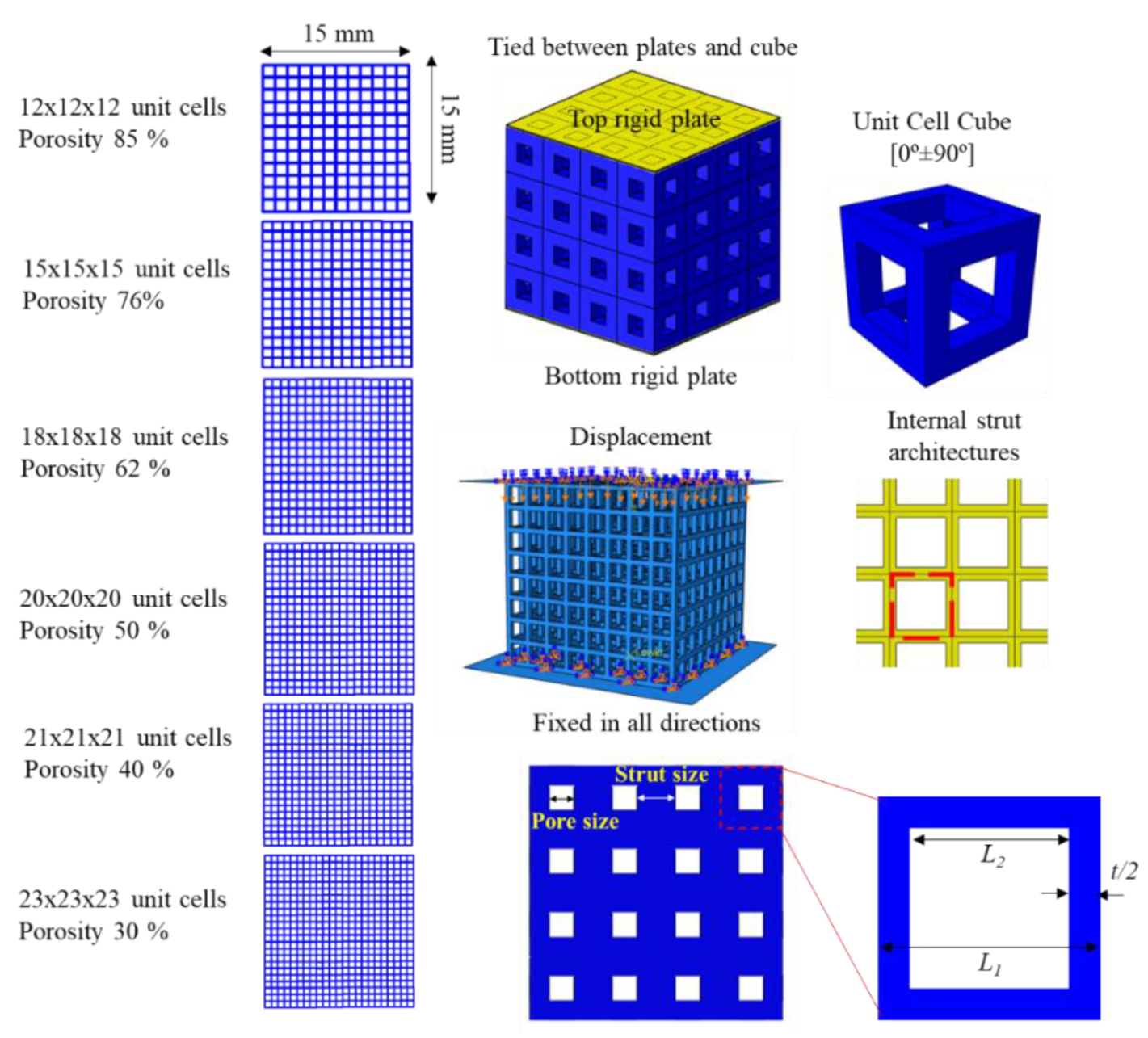
2.1. Design of Porous Microstructures

Three-dimensional models of square porous microstructures with different porosities were modeled in ABAQUS, as shown in Figure 1. These structures were simulated under a compression test to obtain effective mechanical properties. A 3D cube cellular structure (15 mm × 15 mm × 15 mm) was used with six different sizes of pores and strut thicknesses, as shown in Figure 1. The minimum selected strut thickness was 0.3 mm due to the resolution of the EOS M 280 printing machine. Multiple unit cells were introduced into cubic samples of 15 mm dimensional length. The proposed designs were considered with 12–23 unit cells enclosed within each dimensional direction of the cubic samples, as shown in Figure 1. Plates were fixed on the top and bottom side of each cube; the top plate was assigned a displacement boundary condition, whereas the bottom plate was tied up with an encastre boundary condition. The bulk Ti–6Al–4V alloy material properties were assigned to the porous structures. The assembly was meshed using C3D10 quadratic tetrahedral elements with a mesh size of 0.2 mm, which was used based on a sensitivity study driven from stiffness convergence of a solid cube, as shown in Figure 2. Axial displacement on the upper plate was applied to achieve the yield points with increment sizes of 0.05 and with 20 increments to generate a more accurate value of the yield points and modulus of elasticity. The volumetric porosity for the designed porous cubes was calculated based on Equation (1), which was derived from geometric calculations for the designed porous cube. The designed cubes volumetric porosities were compared using the mass properties option in ABAQUS.
V p = L 2     2 N 2   2 N t + 2 t
where Vp = volumetric porosity, L2 = cubic pore inner dimension, N = number of pores in a single cube face, x = full cube dimension, and t = strut thickness.

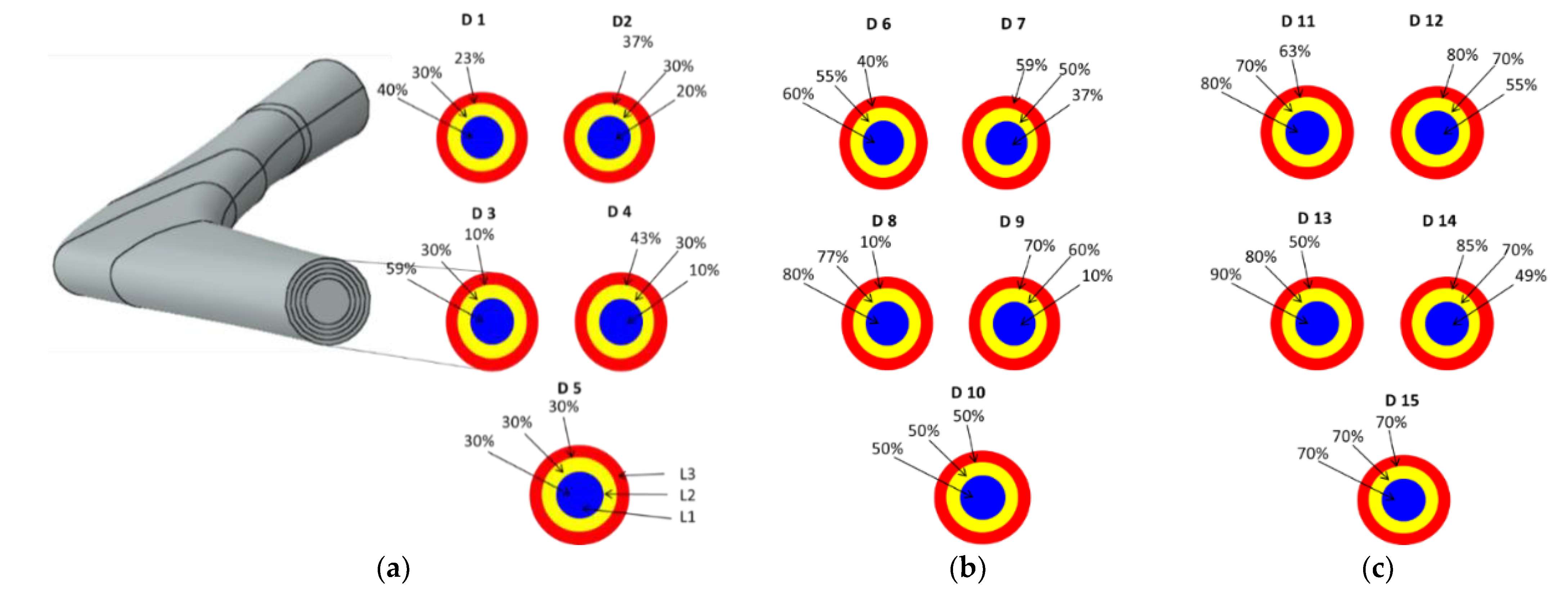
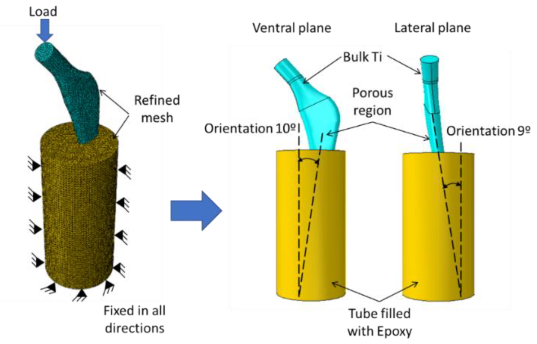
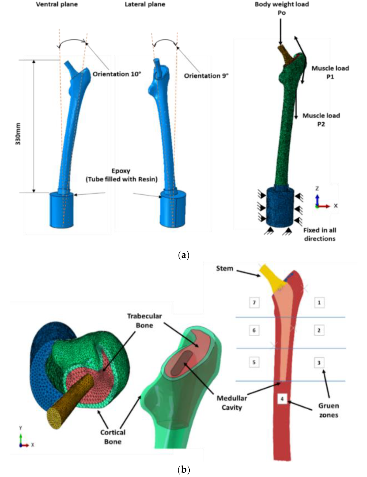
2.2. Design of Porous Stem

The mechanical properties of cubic structures (Figure 1) were used to design twelve different functionally graded stems, as shown in Table 1 and Figure 3. The layer cross sectional areas are 15.9 mm2, 17.3 mm2, and 23.6 mm2 for the core, layer 1, and layer 2, respectively. The average porosities of the designed stems in the radial direction were calculated based on Equation (2). They were grouped into three different sets, each set having the same overall average volumetric porosity throughout the stem’s layers in the radial direction. Three more designs, namely, design D5, D10, and D15, were considered to represent the homogeneous volumetric porosities of 30%, 50%, and 70%, respectively. A total of 15 designs were modeled, as shown in Figure 3. All designs were initially integrated into 3D finite element models, as shown in Figure 4, to study the stiffness performance of the designed stems concerning the intact femur bone. The setup shown in Figure 4 is per the ISO standard (ISO 7206-4).
P ¯ = V P h + A V ¯ p f g A V ¯ p h   A V ¯ p h
where A = the stem’s radial layer cross-sectional area, V p = the stem’s radial layer volumetric porosity, ( A V p ) f g ¯ = average functionally graded porosity, along with the stem’s layers, ( A V p   ) h ¯ = average homogeneous porosity along with the stem’s layers, and ( V p ) h = stem homogenous porosity.
The stem distal end was fixed in epoxy (3.7 GPa), with specific orientations identified in ISO 7206-4, as shown in Figure 4. Then, the stem was tied together with the epoxy, while the epoxy was constrained to move or revolve in any direction. Fine meshes and tetrahedral elements were employed and a 2250 N force [32] was applied on the head of the stem using a 0.1 increment size in 10 increments. The material properties of the bulk Ti and designed porous structures (Table 1) were assigned to the stems based on the simplified FE model to reduce design time and computation [24]. The proximal part of the stem was assigned with bulk Ti material properties.
To study the effect of the designed porous stems on stress reduction and micromotion, it is vital to use a finite element model that incorporates the stem and femur bone along with proper physiological loads. This finite element model has been adopted in previous studies conducted by the authors [5,6,7,8,9]. Three-dimensional models of homogeneous and functionally graded stems (D1–D15) were assembled with femurs using surface-to-surface contact with a coefficient of friction 0.4, and the assembly was inserted into a cylindrical shape epoxy. The bone was tied with the epoxy and restricted to move or rotate in any direction [33,34,35]. The 3D model of the femur was constructed using computed tomography (CT) scanned images of a patient femur, as explained in previous studies [5,36]. Cortical and trabecular bone were considered homogeneous and linear elastic isotrobic material, respectively, with material properties as listed in Table 2 [25,36,37]. The bone was subjected to three physiological loads, namely, P0, P1, and P2, where P0 is the hip contact force and P1 and P2 are muscular forces attached to the femur. These forces were calculated based on the loading of our conditions which are unique and have not been used before [38], as shown in Figure 5a. Table 3 displays these forces in their components (Fx, Fy, Fz). The direction cosines for these component forces were obtained from previous studies [32,38]. The simulation was carried out for three different walking speeds, 1 km/h, 3 km/h, and 5 km/h. The peak hip contact forces used in percent of body weight (%BW) were 293%, 352%, and 471% for walking speeds of 1 km/h, 3 km/h, and 5 km/h, respectively [39,40]. For this study, a human body weight of 900 N was assumed. The assembly was meshed using C3D10 quadratic tetrahedral elements with a mesh size of 3 mm, which was used based on a previous sensitivity study [24]. Bone Gruen zone locations [41] were identified, as illustrated in Figure 5b. These zones will be used for identifying the stress transfer to the bone from the designed stems at the predefined loading conditions.

3. Results and Discussion

For validation purposes, the finite element model of the porous structure used in this study (Section 2.1) was validated with another study [42] that used a cobalt–chrome alloy, as shown in Figure 6. For this validation purpose, the only change made to the existing model is the material property. The cobalt–chrome alloy was selected for the purpose of comparison with existing work reported in the literature. As shown in Figure 6, the finite element model used in this study produces stiffness levels very close to the published work [42].

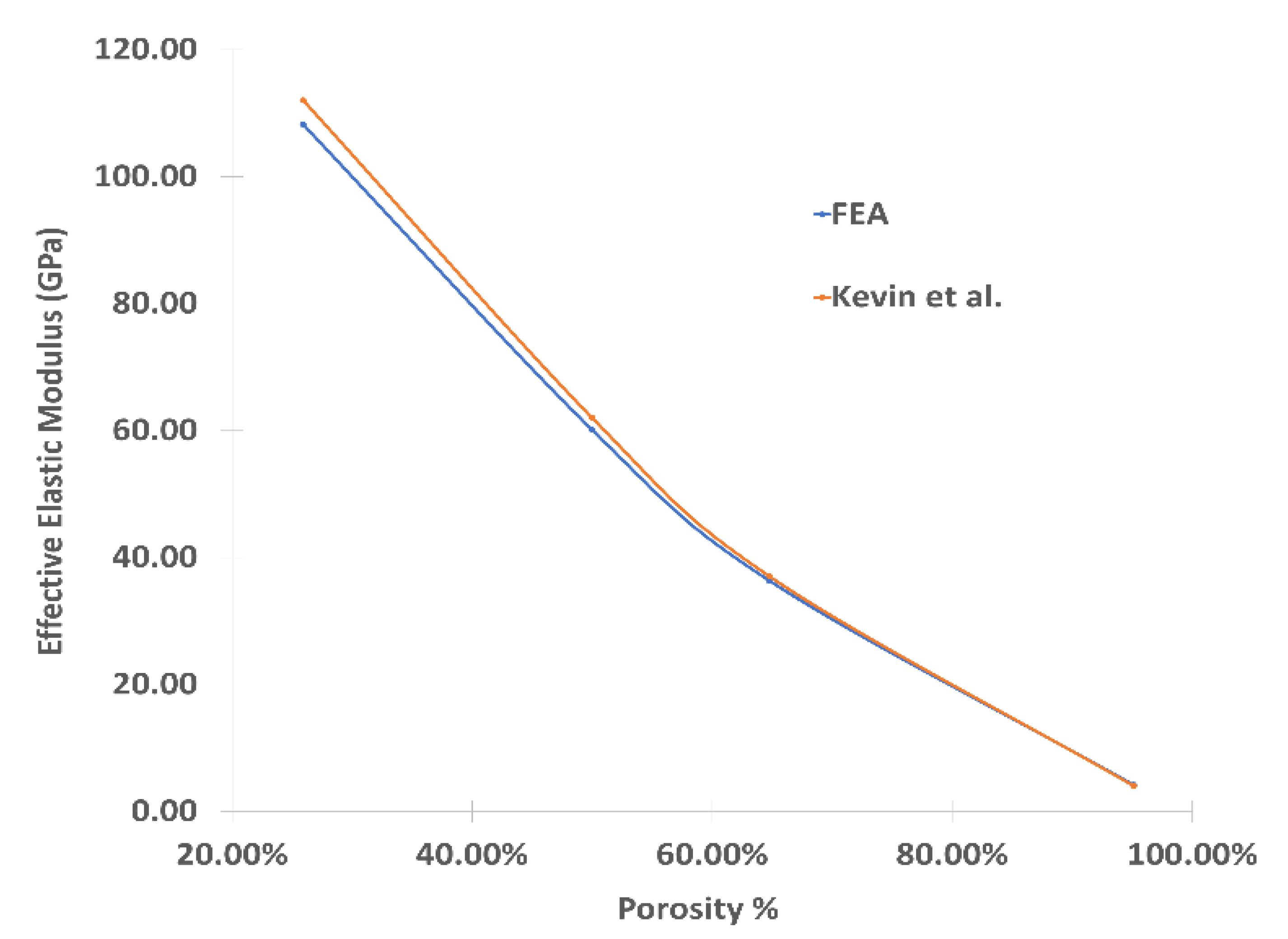
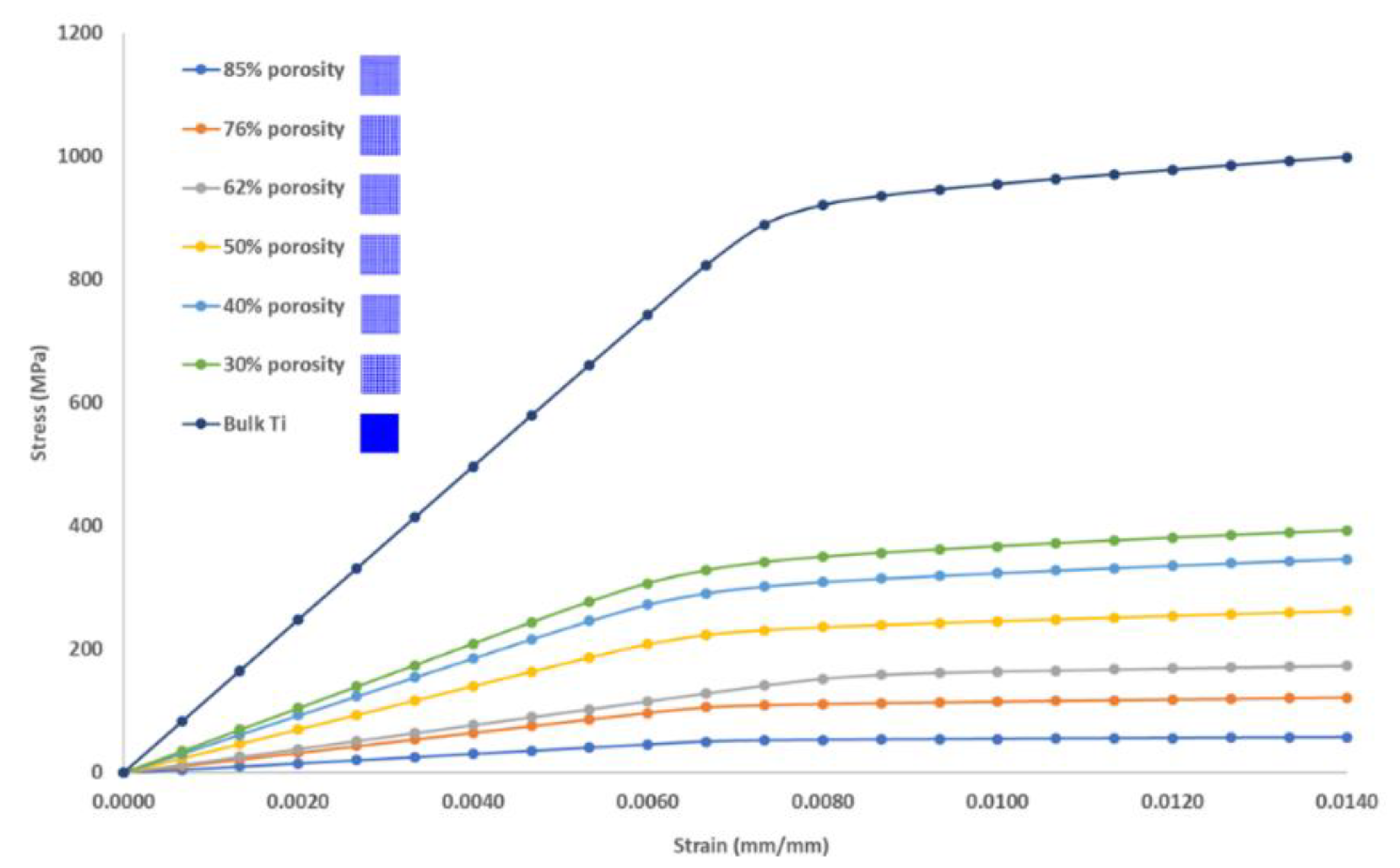
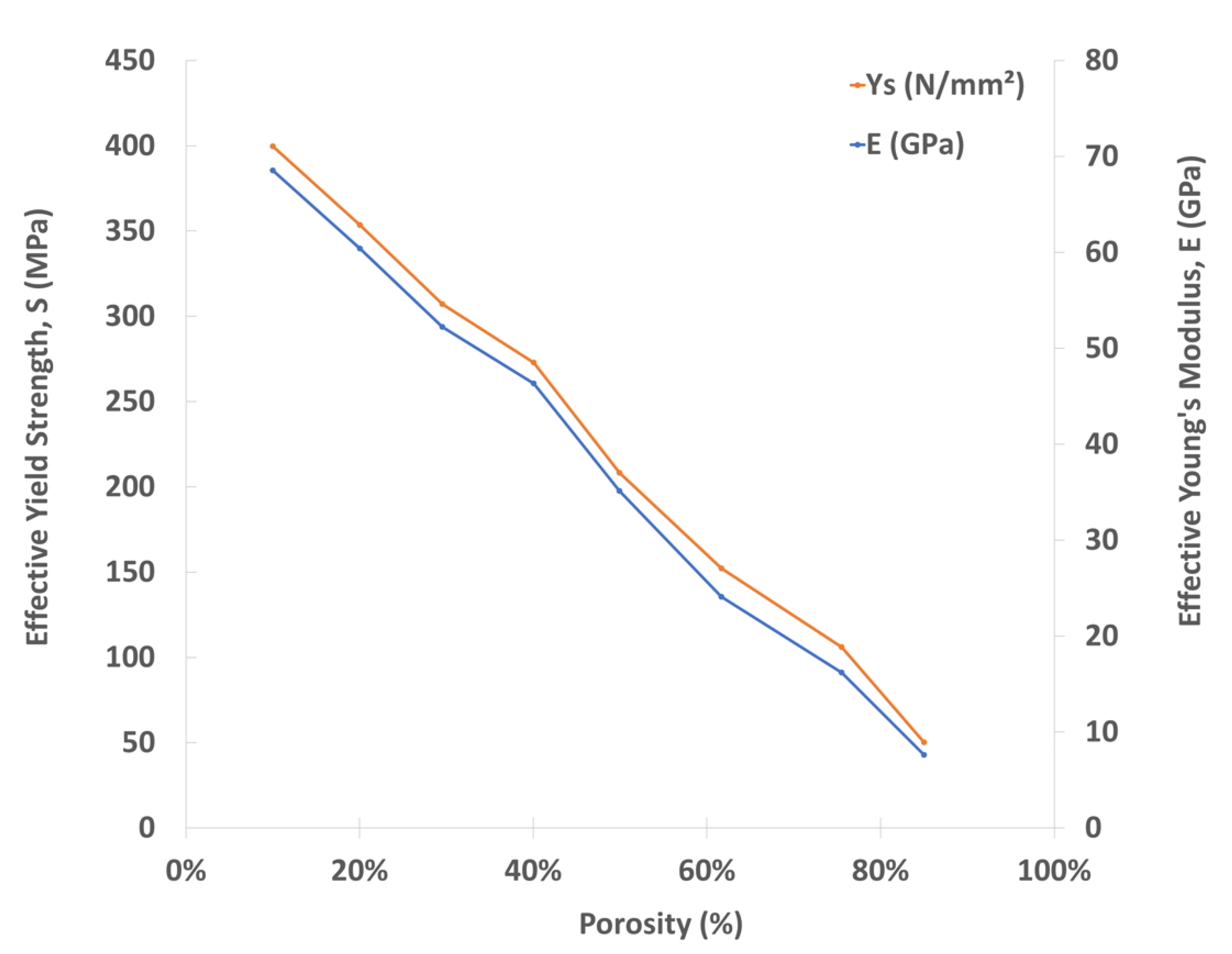
3.1. Mechanical Properties of Porous Cubic Structures

The validated computational model was used to study the stress–strain behavior of the varying porosity cellular structures used in this study. The obtained stress–strain responses with different porosities are shown in Figure 7. This figure also shows the stress–strain response of the bulk Ti with similar dimensions. The effective Young’s modulus of the bulk Ti block was found to be 123.6 GPa, which agrees with the result of Hedayat et al., where the Young’s modulus was found to be 122.3 GPa. It was observed that the yield strength and Young’s modulus increases with decreasing structure porosity, as shown in Figure 8. The results obtained from the finite stress–strain element analysis were used to design the stems (effective Young’s modulus and effective yield strength). Several functionally graded porous designs in the radial direction were developed to achieve the consistent average volumetric porosities of 30%, 50%, and 70%, as listed in Table 1 and illustrated in Figure 3.

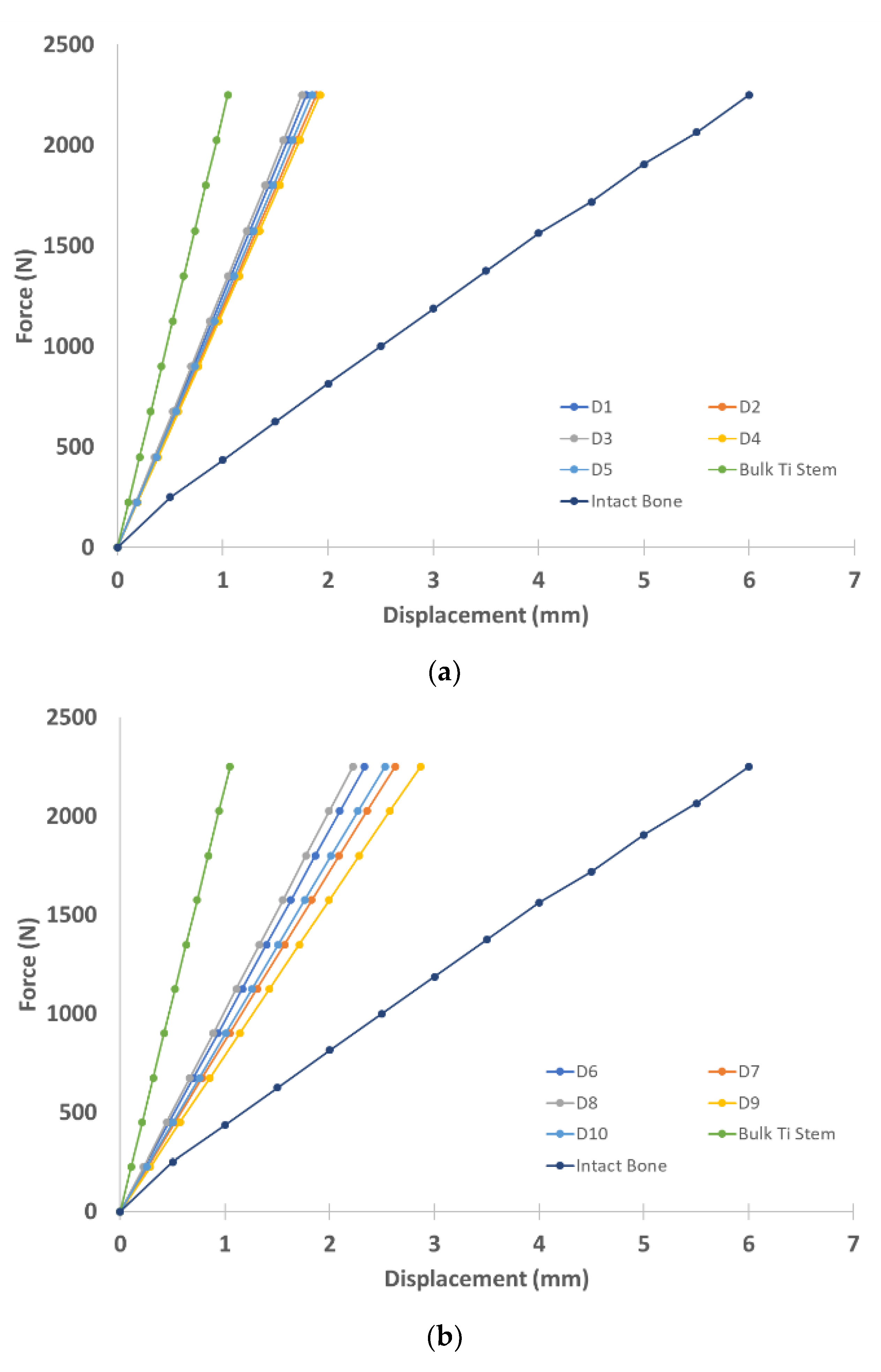
3.2. Biomechanical Performance of Stems

Force–displacement diagrams were plotted for both bulk Ti and the porous stem structures of the stem–eboxy model illustrated in Figure 4 and the results were compared with the intact bone [42] force–displacement response (Figure 9). The stiffness of the porous stem was increased as the volumetric porosity decreased. It is also obvious from the force–displacement curves (Figure 9) that the stems designed with 70% volumetric porosity (functionally graded and homogeneous) were found to offer the best match with the force–displacement diagram of the intact bone. Designs D12 and D14 presented stiffnesses of 361 N/mm and 417 N/mm, respectively, as compared to the intact bone stiffness (375 N/mm) and the bulk Ti stem (2149 N/mm). However, yielding for all stems with an average volumetric porosity of 70% at an applied force of more than 1500 N was observed, in agreement with the findings of previous studies [7,34]; this is attributed to the stresses applied at 2250 N exceeding the yield stresses of the equivalent porous material.
FE models of stem implanted in the bone were validated with the model of Jette et al. [34]. Bulk Ti stem was implanted inside the bone, as illustrated in Figure 10, and subjected to a concentrated load of 3000 N applied in ten increments. The displacement was tracked at a selected point on the bone head. Force–displacement data were plotted and compared with Jette et al.’s experimental results; a strong agreement was noticed between the two models, as shown in Figure 10. It can be concluded from this validation that the difference in implant geometry between Jette et al. and our model has less impact on the results.

3.3. Assessment of Stress Shielding and Micromotions

The stress shielding assessment was performed to evaluate the performance of the stems based on stress distribution along the Gruen zones resulting from the load transfer from the implanted stem to the femur bone. The maximum von Mises stresses for the cortical bone (1–7 Gruen zones) and trabecular bone (1, 2, 6, and 7 Gruen zones), which have direct contact with the stem, were indicated. In general, to reduce stress shielding, an implant should transfer some of the stresses to the bone. The stresses obtained for the 15 functionally graded (FG) designed stems and bulk Ti stem implanted in the femur for the three different walking speeds (1, 3, and 5 km/h) are shown in Figure 11. From these plots, it can be seen that porous Ti stems perform better than bulk Ti stem in terms of reducing stress shielding (high stress values in the bone). There was almost no obvious difference between the FG designs for each average porosity used (30, 50, and 70%), regardless of the walking speed for both areas of the cortical and trabecular bone. The stress transfer to the bone and percent of the reduction in stress shielding is obvious, as shown in Figure 11 and indicated in Table 4. Stress shielding was calculated based on the percent of stress transfer to the bone of the designed FG stems compared with the bulk stem. The transfer of the stresses at the trabecular bone from the designed FG and homogeneous porous stems was more than double that in the bulk stem, indicating a sufficient reduction in stress shielding.
It can be concluded from Figure 11 and Table 4 that the stress transfer from the stem to the bone at Gruen zone 7 increases as the porosity increases, which is associated with lower stiffness at a higher volumetric porosity percentage. These findings agree with previous studies [8,24,34]. It is also evident that the highest stress transfer to the bone at the proximal area is depicted at Gruen zone 7 for all porous stem designs, which is highly required to avoid failure of the hip stem due to stress shielding [21,43], as this zone is susceptible to bone resorption [44]. The distal parts of the stems have higher stress values than the proximal parts, with the maximum value of the stress transfer to the bone for all porous stem designs being found in Gruen zone 4, which is in agreement with the results reported in the literature [21,22,25,43,45]. The inadequate stress transfer to the bone for all porous stem designs at zones 3, 4, and 5 is attributed to the proximal load transfer to the bone, and there is no direct contact with the stem at these areas, this being attributed to torsional stress induced by the applied load [21].
The stresses in the FG stems’ assigned radial layers L1, L2, and L3 (Figure 5) for all proposed 15 FG designs, and the bulk Ti stem are shown in Figure 12. It can be observed that the stresses in the bulk Ti stem are higher than the stresses in the FG stems; however, the stress distributions along the FG stems’ layers were varied, which is attributed to the difference in the Young’s modulus of each porous layer. By studying the yield stress values for each of the stems’ layers, all FG designs were found safe at a walking speed of 1 km/h, except for design D12, in which the stress value at the outer layer is equal to the yield stress associated with 80% porosity. Designs 1, 3, and 8 are safe at 3 km/h walking speed and none of the fifteen designed stems were found to survive at the 5 km/h walking speed due to high stress values which exceeded the yield stresses associated with the porous layers. Most patients receiving THAs usually have a gait speed of less than 2 km/h [46,47]. Detection of a stem’s failure (FS) is calculated as the ratio between the maximum stress found within the stem’s layer (YLmax) and the yield strength associated with the porosity value assigned to the referenced stem’s layer (YsL):
FS = YLmax/YsL
An FS value > 1 for any of a stem’s layers implies that the stem will fail/yield.
Micromotion at the stem–femur interface was studied for the proposed designs, this information being vital to evaluate bone tissue ingrowth, a micromotion value of more than 150 µm being considered excessive and liable to result in the instability of the implant [6,9]. The average micromotion of the proposed designs is illustrated in Figure 13. Stem designs with an average porosity of 70% showed the maximum micromotion values to be greater than 150 µm at 3 km/h and 5 km/h walking speeds besides the design with 50% porosity at 5 km/h, which is attributed to the low stiffness values of the higher porosity stems and the loading conditions associated with the walking speed. These findings agree with the previous studies [8,25]. These designs are highly susceptible to aseptic loosening, which may lead to premature failure of the stem.

4. Conclusions

Three-dimensional finite element models of cubic porous cellular structures were built with porosity values of 30–70% representing fifteen different designs using different arrangements of volumetric porosities within the stems’ layers. The stems were subjected to physiological loads corresponding to three walking speeds (1 km/h, 3 km/h, and 5 km/h). The von Mises stresses at femur Gruen zones and stem layers and the stems’ micromotions were calculated. The conclusions obtained from this study can be summarized as follows:
  • Stems with 70% average porosity were found to have the best match with the intact bone mechanical properties for the stem inside the epoxy model.
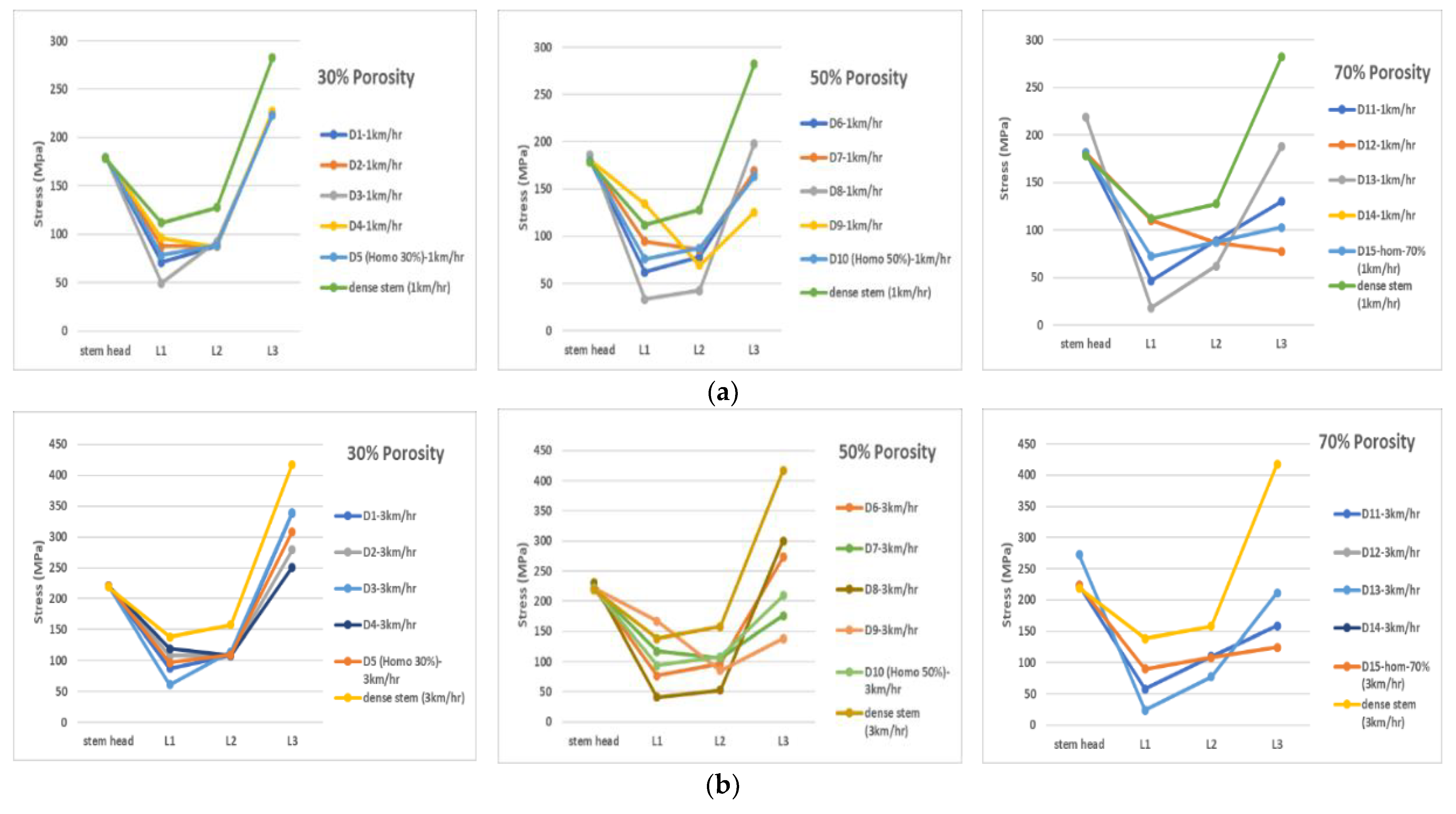
  • Functionally graded porous stems tend to transfer higher stress values to the bone compared to the bulk stem for all physiological loads associated with the three studied walking speeds.
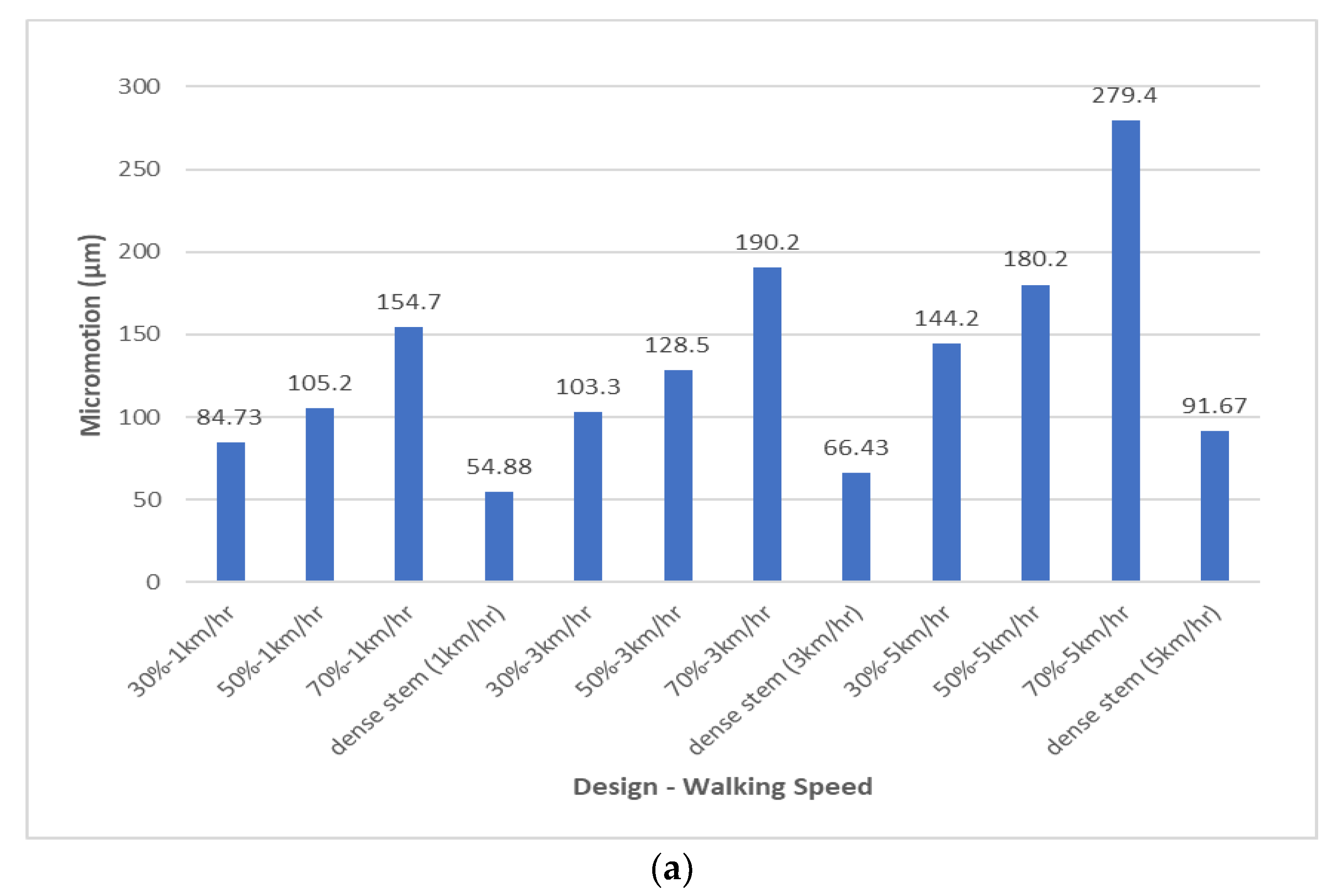
  • Micromotion values increased as the porosity and physiological loads/walking speed increases. Hence, the patient is to be advised to walk at a low speed to prevent the stem’s micromotion, which affects bone tissue ingrowth leads to failure of the implant.
  • Designs associated with stems with an average porosity of 70% at all walking speeds and 50% at 5 km/h walking speed are considered to have failed in terms of micromotion.
  • FG stems of Designs 1 and 3, with 30% average porosity, and Design 8, with 50% average porosity, create moderate interfacial micromotions and enough stress transfer to the bone without yielding. Hence, these designs are recommended as the most suitable candidates to be considered for further studies (fatigue analysis).

Author Contributions

N.F.A.Z.—conceptual idea, analysis, writing of initial draft; F.T.—writing of final draft, supervision, funding; H.M.—writing of final draft; F.J.—writing of final draft. All authors have read and agreed to the published version of the manuscript.

Funding

This paper’s APC was made possible with funding from an NPRP grant, no. NPRP 8-876-2-375.

Acknowledgments

This paper was made possible by an NPRP grant, no. NPRP 8-876-2-375, from the Qatar National Research Fund (a member of Qatar Foundation). The findings achieved herein are solely the responsibility of the authors.

Conflicts of Interest

The authors declare no conflict of interest.

Limitation of the Study

This study is only focused on immediate post-operative conditions of the implanted stems; long-term osseointegration and bone remodeling was not taken into consideration.

References

  1. Garrison, D. Osteoarthritis, Osteoporosis, and Exercise. Work. Health Saf. 2012, 60, 381–383. [Google Scholar] [CrossRef] [PubMed]
  2. De Bellis, U.G.; Legnani, C.; Calori, G.M. Acute total hip replacement for acetabular fractures: A systematic review of the literature. Injury 2014, 45, 356–361. [Google Scholar] [CrossRef] [PubMed]
  3. Kannus, P.; Parkkari, J.; Sievänen, H.; Heinonen, A.; Vuori, I.; Järvinen, M. Epidemiology of hip fractures. Bone 1996, 18, S57–S63. [Google Scholar] [CrossRef]
  4. Singh, J.A.; Yu, S.; Chen, L.; Cleveland, J.D. Rates of Total Joint Replacement in the United States: Future Projections to 2020–2040 Using the National Inpatient Sample. J. Rheumatol. 2019, 46, 1134–1140. [Google Scholar] [CrossRef] [PubMed]
  5. Mehboob, H.; Ahmad, F.; Tarlochan, F.; Mehboob, A.; Chang, S.H. A comprehensive analysis of bio-inspired design of femoral stem on primary and secondary stabilities using mechanoregulatory algorithm. Biomech. Model. Mechanobiol. 2020, 19, 2213–2226. [Google Scholar] [CrossRef] [PubMed]
  6. Mehboob, H.; Tarlochan, F.; Mehboob, A.; Chang, S.-H.; Ramesh, S.; Harun, W.S.W.; Kadirgama, K. A novel design, analysis and 3D printing of Ti-6Al-4V alloy bio-inspired porous femoral stem. J. Mater. Sci. Mater. Med. 2020, 31, 1–14. [Google Scholar] [CrossRef]
  7. Mehboob, H.; Tarlochan, F.; Mehboob, A.; Chang, S.-H. Finite element modelling and characterization of 3D cellular microstructures for the design of a cementless biomimetic porous hip stem. Mater. Des. 2018, 149, 101–112. [Google Scholar] [CrossRef]
  8. Alkhatib, S.E.; Mehboob, H.; Tarlochan, F. Finite Element Analysis of Porous Titanium Alloy Hip Stem to Evaluate the Biomechanical Performance During Walking and Stair Climbing. J. Bionic Eng. 2019, 16, 1103–1115. [Google Scholar] [CrossRef]
  9. Tarlochan, F.; Mehboob, H.; Mehboob, A.; Chang, S.-H. Influence of functionally graded pores on bone ingrowth in cementless hip prosthesis: A finite element study using mechano-regulatory algorithm. Biomech. Model. Mechanobiol. 2017, 17, 701–716. [Google Scholar] [CrossRef]
  10. Labek, G.; Thaler, M.; Janda, W.; Agreiter, M.; Stockl, B. Revision rates after total joint replacement. CUMULATIVE RESULTS FROM WORLDWIDE JOINT REGISTER DATASETS. J. Bone Jt. Surgery. Br. Vol. 2011, 93, 293–297. [Google Scholar] [CrossRef] [Green Version]
  11. Stimac, J.D.; Boles, J.; Parkes, N.; Della Valle, A.G.; Boettner, F.; Westrich, G.H. Revision Total Hip Arthroplasty With Modular Femoral Stems. J. Arthroplast. 2014, 29, 2167–2170. [Google Scholar] [CrossRef] [PubMed]
  12. Khatod, M.; Cafri, G.; Namba, R.S.; Inacio, M.; Paxton, E.W. Risk Factors for Total Hip Arthroplasty Aseptic Revision. J. Arthroplast. 2014, 29, 1412–1417. [Google Scholar] [CrossRef] [PubMed]
  13. Memtsoudis, S.G.; Besculides, M.C.; Gaber, L.; Liu, S.; Della Valle, A.G. Risk factors for pulmonary embolism after hip and knee arthroplasty: A population-based study. Int. Orthop. 2008, 33, 1739–1745. [Google Scholar] [CrossRef] [PubMed] [Green Version]
  14. Bayliss, L.E.; Culliford, D.; Monk, A.P.; Glyn-Jones, S.; Prieto-Alhambra, D.; Judge, A.; Cooper, C.; Carr, A.J.; Arden, N.K.; Beard, D.J.; et al. The effect of patient age at intervention on risk of implant revision after total replacement of the hip or knee: A population-based cohort study. Lancet 2017, 389, 1424–1430. [Google Scholar] [CrossRef] [Green Version]
  15. Gil, L.; Brühl, S.; Jiménez, L.; Leon, O.; Guevara, R.; Staia, M.H. Corrosion performance of the plasma nitrided 316L stainless steel. Surf. Coatings Technol. 2006, 201, 4424–4429. [Google Scholar] [CrossRef]
  16. Healy, W.L.; Tilzey, J.F.; Iorio, R.; Specht, L.M.; Sharma, S. Prospective, Randomized Comparison of Cobalt-Chrome and Titanium Trilock Femoral Stems. J. Arthroplast. 2009, 24, 831–836. [Google Scholar] [CrossRef]
  17. Niinomi, M. Mechanical biocompatibilities of titanium alloys for biomedical applications. J. Mech. Behav. Biomed. Mater. 2008, 1, 30–42. [Google Scholar] [CrossRef]
  18. Niinomi, M. Recent metallic materials for biomedical applications. Met. Mater. Trans. A 2002, 33, 477–486. [Google Scholar] [CrossRef]
  19. Chen, J.-H.; Liu, C.; You, L.; Simmons, C.A. Boning up on Wolff’s Law: Mechanical regulation of the cells that make and maintain bone. J. Biomech. 2010, 43, 108–118. [Google Scholar] [CrossRef]
  20. Kurtz, S.; Ong, K.; Lau, E.; Mowat, F.; Halpern, M. Projections of Primary and Revision Hip and Knee Arthroplasty in the United States from 2005 to 2030. J. Bone Jt. Surg. 2007, 89, 780–785. [Google Scholar] [CrossRef]
  21. Oshkour, A.; Abu Osman, N.; Bayat, M.; Afshar, R.; Berto, F. Three-dimensional finite element analyses of functionally graded femoral prostheses with different geometrical configurations. Mater. Des. 2014, 56, 998–1008. [Google Scholar] [CrossRef]
  22. Hazlehurst, K.B.; Wang, C.J.; Stanford, M. A numerical investigation into the influence of the properties of cobalt chrome cellular structures on the load transfer to the periprosthetic femur following total hip arthroplasty. Med Eng. Phys. 2014, 36, 458–466. [Google Scholar] [CrossRef] [PubMed]
  23. Schmidutz, F.; Agarwal, Y.; Müller, P.; Gueorguiev, B.; Richards, R.; Sprecher, C. Stress-shielding induced bone remodeling in cementless shoulder resurfacing arthroplasty: A finite element analysis and in vivo results. J. Biomech. 2014, 47, 3509–3516. [Google Scholar] [CrossRef]
  24. Alkhatib, S.E.; Tarlochan, F.; Mehboob, H.; Singh, R.; Kadirgama, K.; Harun, W.S.W. Finite element study of functionally graded porous femoral stems incorporating body-centered cubic structure. Artif. Organs 2019, 43, E152–E164. [Google Scholar] [CrossRef] [PubMed]
  25. Limmahakhun, S.; Oloyede, A.; Sitthiseripratip, K.; Xiao, Y.; Yan, C. Stiffness and strength tailoring of cobalt chromium graded cellular structures for stress-shielding reduction. Mater. Des. 2017, 114, 633–641. [Google Scholar] [CrossRef]
  26. Sharma, G.K.; Gurumoorthy, B. Iso-material contour representation for process planning of heterogeneous object model. J. Comput. Des. Eng. 2020, 7, 498–513. [Google Scholar] [CrossRef]
  27. Velasco, M.; Lancheros, Y.; Garzón-Alvarado, D.A. Geometric and mechanical properties evaluation of scaffolds for bone tissue applications designing by a reaction-diffusion models and manufactured with a material jetting system. J. Comput. Des. Eng. 2016, 3, 385–397. [Google Scholar] [CrossRef] [Green Version]
  28. Park, J.; Ahn, S.-J.; Lee, H.; Noh, G. Implant placement in the removable mandibular advancement device for completely edentulous patients: A finite element study. J. Comput. Des. Eng. 2021, 8, 140–148. [Google Scholar] [CrossRef]
  29. Bagheri, M.A.; Rouhi, G. Design and numerical investigation of an adaptive intramedullary nail with a novel interlocking mechanism. J. Comput. Des. Eng. 2020, 7, 722–735. [Google Scholar] [CrossRef]
  30. Kim, W.; Veloso, A.P.; Araújo, D.; Kohles, S.S. Novel computational approaches characterizing knee physiotherapy. J. Comput. Des. Eng. 2014, 1, 55–66. [Google Scholar] [CrossRef] [Green Version]
  31. Yoon, Y.; Kim, J.-E.; Jung, J.; Oh, S.-H.; Noh, G.; Kwon, Y.-D. Effect of mandibular contouring surgery on the stress distribution during various clenching tasks. J. Comput. Des. Eng. 2021, 8, 570–580. [Google Scholar] [CrossRef]
  32. Bergmann, G.; Deuretzbacher, G.; Heller, M.; Graichen, F.; Rohlmann, A.; Strauss, J.; Duda, G. Hip contact forces and gait patterns from routine activities. J. Biomech. 2001, 34, 859–871. [Google Scholar] [CrossRef]
  33. Hedayati, R.; Hosseini-Toudeshky, H.; Sadighi, M.; Mohammadi-Aghdam, M.; Zadpoor, A. Computational prediction of the fatigue behavior of additively manufactured porous metallic biomaterials. Int. J. Fatigue 2016, 84, 67–79. [Google Scholar] [CrossRef] [Green Version]
  34. Jetté, B.; Brailovski, V.; Simoneau, C.; Dumas, M.; Terriault, P. Development and in vitro validation of a simplified numerical model for the design of a biomimetic femoral stem. J. Mech. Behav. Biomed. Mater. 2018, 77, 539–550. [Google Scholar] [CrossRef]
  35. Simoneau, C.; Terriault, P.; Jetté, B.; Dumas, M.; Brailovski, V. Development of a porous metallic femoral stem: Design, manufacturing, simulation and mechanical testing. Mater. Des. 2017, 114, 546–556. [Google Scholar] [CrossRef]
  36. Oshkour, A.; Davoodi, M.; Abu Osman, N.; Yau, Y.; Tarlochan, F.; Abas, W.W. Finite element analysis of circumferential crack behavior in cement–femoral prosthesis interface. Mater. Des. 2013, 49, 96–102. [Google Scholar] [CrossRef] [Green Version]
  37. Yeni, Y.N.; Wu, B.; Huang, L.; Oravec, D. Mechanical Loading Causes Detectable Changes in Morphometric Measures of Trabecular Structure in Human Cancellous Bone. J. Biomech. Eng. 2013, 135, 054505–0545055. [Google Scholar] [CrossRef] [Green Version]
  38. Miura, M.; Nakamura, J.; Matsuura, Y.; Wako, Y.; Suzuki, T.; Hagiwara, S.; Orita, S.; Inage, K.; Kawarai, Y.; Sugano, M.; et al. Prediction of fracture load and stiffness of the proximal femur by CT-based specimen specific finite element analysis: Cadaveric validation study. BMC Musculoskelet. Disord. 2017, 18, 536. [Google Scholar] [CrossRef]
  39. Bergmann, G.; Graichen, F.; Rohlmann, A. Hip joint loading during walking and running, measured in two patients. J. Biomech. 1993, 26, 969–990. [Google Scholar] [CrossRef]
  40. Heller, M.; Bergmann, G.; Kassi, J.-P.; Claes, L.; Haas, N.; Duda, G. Determination of muscle loading at the hip joint for use in pre-clinical testing. J. Biomech. 2005, 38, 1155–1163. [Google Scholar] [CrossRef]
  41. Cavalli, L.; Brandi, M.L. Periprosthetic bone loss: Diagnostic and therapeutic approaches. F1000Research 2014, 2, 266. [Google Scholar] [CrossRef] [PubMed] [Green Version]
  42. Hazlehurst, K.; Wang, C.J.; Stanford, M. Evaluation of the stiffness characteristics of square pore CoCrMo cellular structures manufactured using laser melting technology for potential orthopaedic applications. Mater. Des. 2013, 51, 949–955. [Google Scholar] [CrossRef]
  43. Morrey, B. Cementless Femoral Fixation in Total Hip Arthroplasty. Yearb. Orthop. 2011, 2011, 148–149. [Google Scholar] [CrossRef]
  44. Alm, J.J.; Mäkinen, T.J.; Lankinen, P.; Moritz, N.; Vahlberg, T.; Aro, H.T. Female patients with low systemic BMD are prone to bone loss in Gruen zone 7 after cementless total hip arthroplasty. Acta Orthop. 2009, 80, 531–537. [Google Scholar] [CrossRef]
  45. Pitto, R.P.; Hayward, A.; Walker, C.; Shim, V.B. Femoral bone density changes after total hip arthroplasty with uncemented taper-design stem: A five year follow-up study. Int. Orthop. 2009, 34, 783–787. [Google Scholar] [CrossRef] [PubMed] [Green Version]
  46. Morri, M.; Natali, E.; Tosarelli, D. At discharge gait speed and independence of patients provides a challenges for rehabilitation after total joint arthroplasty: An observational study. Arch. Physiother. 2016, 29, 6. [Google Scholar] [CrossRef] [PubMed] [Green Version]
  47. Gerhardt, D.M.J.M.; Ter Mors, T.G.; Hannink, G.; Van Susante, J.L.C. Resurfacing hip arthroplasty better preserves a normal gait pattern at increasing walking speeds compared to total hip arthroplasty. Acta Orthop. 2019, 90, 231–236. [Google Scholar] [CrossRef] [Green Version]
Figure 1. Porous structure designs along with finite element model to study the mechanical properties.
Applsci 12 01548 g001
Figure 2. Sensitivity study to indicate the mesh size to which the modulus of elasticity converges using a solid cube.
Applsci 12 01548 g002
Figure 3. Porous functionally graded and homogeneous designs introduced to stem redial layers: (a) average porosity of 30%, (b) average porosity of 50%, (c) average porosity of 70%.
Applsci 12 01548 g003
Figure 4. Finite element analysis of dense and porous Ti stems according to the ISO 7206-4 standard.
Applsci 12 01548 g004
Figure 5. Finite element analysis of stemmed femur: (a) complete finite element model with applied physiological loads, (b) bone Gruen zones.
Applsci 12 01548 g005
Figure 6. Validation of porous structures against FEA results of Kevin et al.
Applsci 12 01548 g006
Figure 7. Stress–strain diagram for the designed porous cubes with relevant volumetric porosities.
Applsci 12 01548 g007
Figure 8. Effective yield strength and effective Young’s modulus with varying porosities obtained from the finite element simulation.
Applsci 12 01548 g008
Figure 9. Force–displacement diagram for stem designs with (a) 30%, (b) 50%, and (c) 70% volumetric porosities, respectively, along with intact bone and bulk Ti stem.
Applsci 12 01548 g009aApplsci 12 01548 g009b
Figure 10. Stem–bone assembly validation.
Applsci 12 01548 g010
Figure 11. Stresses at Gruen zones of the functionally graded porous stems and the bulk Ti stem for proposed designs for different walking speeds: (a) 1 km/h, (b) 3 km/h, (c) 5 km/h.
Applsci 12 01548 g011aApplsci 12 01548 g011b
Figure 12. Von Mises stresses at the FG stems’ layers and the bulk Ti stem: at (a) 1 km/h, (b) 3 km/h, and (c) 5 km/h walking speeds.
Applsci 12 01548 g012aApplsci 12 01548 g012b
Figure 13. (a) Maximum micromotion and (b) average micromotion of the designed FG stems vs. the bulk stem at 1, 3, and 5 km/hr walking speeds. (c) Graphical representation of micromotion in the bone (typical example).
Applsci 12 01548 g013aApplsci 12 01548 g013b
Table 1. Porous functionally graded (FG) and homogeneous (H) designs introduced to stem redial layers.
30% Overall Volumetric Porosity
Stem LayersFG-Design 1 (D1)FG-Design 2 (D2)FG-Design 3 (D3)FG-Design 4 (D4)H-Design 5
(D5)
Layer 1
(L1-Core)
40%20%59%10%30%
Layer 2 (1 mm)
(L2)
30%30%30%30%
Layer 3 (1 mm)
(L3)
23%37%10%43%
50% Overall Volumetric Porosity
Stem LayersFG-Design 6 (D6)FG-Design 7 (D7)FG-Design 8 (D8)FG-Design 9 (D9)H-Design 10
(D10)
Layer 1
(L1-Core)
60%37%80%10%50%
Layer 2 (1 mm)
(L2)
55%50%77%60%
Layer 3 (1 mm)
(L3)
40%59%10%70%
70% Overall Volumetric Porosity
Stem LayersFG-Design 11 (D11)FG-Design 12 (D12)FG-Design 13 (D13)FG-Design 14 (D14)H-Design 15
(D15)
Layer 1
(L1-Core)
80%55%90%49%70%
Layer 2 (1 mm)
(L2)
70%70%80%70%
Layer 3 (1 mm)
(L3)
63%80%50%85%
Table 2. Femur material properties utilized for the finite element model [21,33] (Hedayati et al., 2016; AA Oshkour et al., 2014).
Bone MaterialYoung’s Modulus (GPa)Shear Modulus (GPa)Poisson’s Ratio
Spongy bone (trabecular bone)0.4-0.3
Cortical boneExx = 11.5Gxy = 3.6νxy = 0.51
Eyy = 11.5Gyz = 3.3νyz = 0.31
Ezz = 17Gyz = 3.3νyz = 0.31
Table 3. Body weight and muscular loads for different walking speeds [39,40] (with reference to Bergmann et al., 1993, Heller et al., 2005).
Force
(Body Weight Used BW = 900 N)
%Po1 km/h
(Po = 293% BW)
3 km/h
(Po = 352% BW)
5 km/h
(Po = 471% BW)
FxFyFzFxFyFzFxFyFz
Po100−599−363−2542−719−437−3054−962−584−4086
P1446438.095977257.31152103476.71542
P1-tensor fascia latae, proximal part879.912914695.9154175128206235.4
P1-tensor fascia latae, distal part8−5.5−7.8−210−6.7−9.3−253−8.9−12.5−338
P240−10.0205−1030−12.0246−1237−16.0329.9−1656
Table 4. Stress transfer percentages of the functionally graded porous stems in comparison to the bulk Ti (reduction in stress shielding).
1 km/h
DesignLocationG 1G 2G 3G 4G 5G 6G 7
30% PorosityTrabecular bone27.1%9.4%2.5%1.2%4.9%10.4%35.9%
50% PorosityTrabecular bone35.8%12.2%4.5%1.8%6.6%16.1%48.1%
70% PorosityTrabecular bone46.1%20.3%6.6%2.8%8.6%22.3%62.6%
3 km/h
DesignLocationG 1G 2G 3G 4G 5G 6G 7
30% PorosityTrabecular bone21.8%9.5%2.2%1.5%5.2%10.2%36.1%
50% PorosityTrabecular bone31.8%12.3%4.3%2.2%7.0%16.0%48.4%
70% PorosityTrabecular bone41.4%19.8%6.6%3.5%9.1%22.1%63.1%
5 km/h
DesignLocationG 1G 2G 3G 4G 5G 6G 7
30% PorosityTrabecular bone20.3%10.5%2.2%2.2%5.8%9.9%36.6%
50% PorosityTrabecular bone30.5%12.9%4.1%3.3%7.8%15.9%49.2%
70% PorosityTrabecular bone40.0%19.2%6.8%5.2%10.2%22.4%64.9%
Publisher’s Note: MDPI stays neutral with regard to jurisdictional claims in published maps and institutional affiliations.

