Article

Characteristics of 2.45 GHz Surface-Wave-Sustained Argon Discharge for Bio-Medical Applications

1
Plasma Technology Laboratory, Clean & Circle Center of Competence, Sofia University, 1164 Sofia, Bulgaria
2
Faculty of Forest Industry, University of Forestry, 1756 Sofia, Bulgaria
3
Department of Physiology and Pathophysiology, Faculty of Medicine, Medical University of Sofia, 1431 Sofia, Bulgaria
4
Department of Medical Physics and Biophysics, Faculty of Medicine, Medical University of Sofia, 1431 Sofia, Bulgaria
5
Research Group PLASMANT, Department of Chemistry, University of Antwerp, 2610 Antwerp, Belgium
6
Faculty of Physics, Sofia University, 1164 Sofia, Bulgaria
*
Author to whom correspondence should be addressed.
Appl. Sci. 2022, 12(3), 969; https://doi.org/10.3390/app12030969
Submission received: 20 December 2021 / Revised: 12 January 2022 / Accepted: 14 January 2022 / Published: 18 January 2022
(This article belongs to the Special Issue Frontiers in Atmospheric Pressure Plasma Technology)

Abstract

:

Feature Application

A cold microwave plasma torch operating at low wave power at atmospheric pressure can be successfully used for treatment of biological systems in medicine and agriculture without thermal damage and any unwanted and unacceptable effects of the microwave radiation but with high bactericidal, virucidal and fungicidal effects without the use of harmful chemicals.

Abstract

Cold atmospheric plasma (CAP) applications in various fields, such as biology, medicine and agriculture, have significantly grown during recent years. Many new types of plasma sources operating at atmospheric pressure in open air were developed. In order to use such plasmas for the treatment of biological systems, plasma properties should fulfil strong requirements. One of the most important is the prevention from heating damage. That is why in many cases, the post-discharge region is used for treatment, but the short living particles in the active discharge zone and reactions with them are missed in that case. We use the active region of surface-wave-sustained argon plasma for biological systems treatment. The previous investigations showed good bactericidal, virucidal, seeds germination and decontamination effects at a short treatment time, but the discharge conditions for bio-medical applications need specific adjustment. A detailed theoretical and experimental investigation of the plasma characteristics and their possible optimization in order to meet the requirements for bio-medical applications are presented in this paper. The length of the plasma torch, the temperature at the treatment sample position and the microwave radiation there are estimated and optimized by the appropriate choice of discharge tube size, argon flow rate and microwave power.

1. Introduction

The low-temperature, non-equilibrium atmospheric pressure plasmas have attracted increasing interest as simple and less expensive plasma sources operating in open space for applications in biology, medicine, agriculture, and the food industry [1,2,3,4,5,6,7,8,9,10]. Various types of atmospheric pressure plasma sources were developed for such applications. Initially, the plasma produced at atmospheric pressure was with a temperature much higher than 40 °C, and mainly the thermal effects of plasma were used, as in the argon plasma coagulation device [11,12]. Later on, the investigations were focused on developing plasma sources producing plasma at atmospheric pressure with a gas temperature low enough (below 40 °C, so-called cold atmospheric plasma—CAP) in order to avoid the destructive effects and damaging of heat-sensitive materials and biological systems. Two main requirements are formulated in [1] for the direct application of plasma “on or in the human (or animal) body” and they are the same for treatment in vivo or in vitro of any biological system, including seeds, plants, fresh fruits, etc.: (i) good stability and reproducibility of the plasma source operating at atmospheric pressure in the open space; and (ii) low temperature (<40 °C) at the tissue (sample) contact zone to avoid thermal destruction.
Various types of plasma devices for these purposes were developed in recent years. The most widely studied and used plasma sources for bio-medical applications in various configurations and designs are based on the dielectric barrier discharge (DBD) and the atmospheric pressure plasma jets (APPJ) [13,14,15]. In [16], the plasma sources (assuming that the plasma is produced between electrodes) are categorized in three types: (i) direct plasma sources, when one of the electrodes is the sample (human body); (ii) indirect plasma sources, when the plasma is produced between two electrodes and the active plasma components are transported to the treated sample; and (iii) hybrid plasma sources—surface micro discharge (SMD) technology. A detailed review of non-thermal atmospheric pressure plasma sources for various applications and their plasma characteristics is presented in [17], and in [18] the focus is on plasma sources for medical purposes.
The strategies for controlling the physical properties of the plasma for bio-medical applications and for keeping the plasma parameters bellow the damaging limits at the treatment area include the following: (i) using low electrical power; (ii) high frequency (kHz to MHz) or pulsed regime of operation; and (iii) appropriate choice of gas or gas mixture and the gas flow rate for plasma production. One of the CE certified as a medical device plasma source is the kINPen [19]. Various modifications exist under this name, and they operate in different regimes (power from 1.9 W up to 120 W; frequency from 0.8 MHz to 27.12 MHz; gases Ar, He + 2% molecular gas admixture, air with flow rates usually 3–5 slm) and one of them (the kINPen MED) is actually CE certified as a medical device. It needs about 10 years to decrease the operating temperature from about 80 °C [20,21,22] to 35–38 °C. In [23], the kINPen is compared with another plasma source, MicroPlaSter, which is also CE certified for medical use. The MicroPlaSter operates at 2.45 GHz and 80–110 W electrical power. Both devices use plasma, which is transported out of the ignition region by the gas flow. For MicroPlaSter, the gas flow rate is 2–5 L/min, and the distance between the device nozzle and the treated sample is fixed to 2 cm by a plastic spacer. The diameter of the treated area is 1 cm2 with kINPen and 4–5 cm2 with MicroPlaSter. The treatment time is also a very important parameter, and it is shown in [23] that the treatment time with kINPen can vary from 20 s to 5 min, and with MicroPlaSter, it is usually 2–5 min.
Another type of plasma source operating at atmospheric pressure and a microwave frequency of 2.45 GHz, the surface-wave-sustained discharge (SWD) was investigated for possible applications in biology, medicine, agriculture, and the food industry [24,25,26,27,28,29,30]. The specific way of plasma produced and sustained by an electromagnetic wave traveling along the plasma–dielectric interface (surface wave) determines the features of these discharges.
Surface-wave-sustained discharges operating at low and intermediate pressure have already a successful history after several types of wave launcher were introduced by Moisan in 1974 [31,32,33,34,35]. The good stability and reproducibility of these electrodeless discharges in a wide range of discharge conditions are very important characteristics for applications and the reason for intensive investigation during the past decades. A detailed review of these investigations can be found in [36,37]. For these discharges, the operating frequency can vary from MHz to GHz. The discharge tube diameter, thickness and dielectric permittivity play a very important role for the characteristics of the plasma sustained inside it because the tube is not only a container for sustaining the plasma, but is an important part of the waveguide structure for the electromagnetic wave propagation. The plasma itself is also a part of the same waveguide, and its properties can be easily controlled by appropriate selection of the discharge tube geometric parameters and permittivity. The plasma density (electron number density) decreases almost linearly from the wave launcher to the plasma column end. The plasma can be much longer that the size of the wave launcher, and its length depends on the wave power. The theoretical and experimental investigations of SWD at this period are at low and intermediate gas pressure [37,38]. It is shown that at these discharge conditions, the plasma is a strongly non-equilibrium one: the electron energy distribution function (EEDF) is non-Maxwellian; because of this, the electron temperature Te is defined as 2/3 of the mean electron energy <u> obtained from the calculated EEDF (Te = 2<u>/3); and the electron temperature is much higher than the gas temperature (the temperature of the heavy particles in the plasma), Te >> Tg.
The situation is more complicated for SWD operating at atmospheric pressure. A stable atmospheric pressure plasma inside the discharge tube or going outside it (plasma torch) can be sustained by high wave power, which leads to high gas temperature. In [39], stable argon plasma with an electron density of about 3 × 10²⁰ m−3 and gas temperature of 2500 K is produced by 70 W wave power at 915 MHz and gas flow from 0.2 to 17 L/min. It is mentioned there that at a wave power above 200 W, the surfatron wave exciter needs external water cooling. The further surface wave plasma torch development is directed toward devices operating at high power and with high gas temperature (4000–8000 K) for applications in cutting, welding, material processing [40], carbon dioxide elimination [41] and many others [42]. Being electrodeless, the corrosion of electrodes and plasma contamination is avoided, and a precise, clean composition of working gases and gas mixtures can be achieved.
Producing a stable and well-reproducible surface-wave plasma torch at low wave power with low gas temperature is a tricky challenge. The filamentation in pure argon is one of the problems at atmospheric pressure SWD [43]. By adding a small amount of nitrogen, the filamentation can be eliminated [25,44] but the gas temperature of the Ar + N plasma is much higher than is appropriate for bio-medical applications. It is possible to obtain a single filament discharge in pure argon when the discharge tube is with a small radius, but this requires a higher wave frequency in the microwave range, e.g., 2.45 GHz. The electromagnetic waves in the microwave region may also have unacceptable biological effects, which need further investigation. For the direct treatment of biological samples, the plasma must come out of the discharge tube, i.e., we need a plasma torch (Figure 1). The surface-wave argon plasma torch can be produced in a gas flow regime by increasing of the wave power so that the electromagnetic surface wave propagation along the plasma–dielectric interface continues along the plasma–air boundary. The part of the plasma outside the tube is not an afterglow, but an active discharge region with high enough wave power for sustaining plasma, which leads to a higher temperature. At the same time, for bio-medical application, it is important to keep the gas temperature of the sustained plasma below 40 °C.
We found some regimes of operation allowing a microwave plasma torch to be applied for the treatment of biological systems without thermal damage. The investigations show high bactericidal [24] and virucidal [26] effects at very short treatment time (5–30 s). This treatment time is much shorter than the typical 2–5 min of MicroPlaSter [23]. Promising results are also obtained for the decontamination of seeds, plants, and fruits at a similarly short treatment time by a microwave plasma torch [28,29,30]. Some preliminary experiments on wound treatment on mice [27] also stimulate the investigations in these directions. The reactive oxygen and nitrogen (RONS) species important for bio-medical plasma effects are produced, even when the working gas is pure argon as a result of the interaction of the plasma torch with ambient air [25].
The biggest problem of the microwave plasma torches sustained by a traveling wave that needs systematic investigation is that by using the same (low) wave power and gas flow, in some cases, the temperature at the plasma torch tip is low enough to be touched (Figure 1) and in other cases, can be above 100 °C [25]. In some conditions, only one stable filament exists, while at the same wave power and gas flow, a second filament can appear. Another important difference between the surface wave plasma torch and the MicroPlaSter device [23] is connected with the microwave field used for the plasma ignition. The microwave electric field in MicroPlaSter is applied between electrodes inside a metal container, and the plasma is transported outside the active region by the gas flow. In this way, the treated sample is prevented from the microwave radiation, but only long-living active plasma particles can be used for the treatment process. The surface wave plasma torch is produced by an electromagnetic wave traveling along the plasma with the wave power decreasing along the torch. At low and intermediate pressures, the end of the plasma column is at a position where the wave power becomes zero and the wave cannot propagate anymore. At high and atmospheric pressures, the wave power for sustaining plasma is much higher, and the plasma column ends when the wave power is not enough for sustaining plasma, but usually is not zero. The plasma used for the samples treatment is a part of the active discharge region with all short- and long-living particles produced in the plasma (which can be the reason for obtaining good results at very short treatment time), but also the microwave field there may be too high. It is important to investigate the microwave radiation at the position of the treated sample in order to avoid any possible damage during the treatment.
The purpose of this work is to investigate the parameters of the surface-wave-sustained plasma torch and to find the well-reproducible discharge conditions at which the plasma is appropriate for bio-medical applications. The dependance of the plasma torch length, the temperature of the treated samples, the microwave radiation at the samples on the wave power and discharge tube geometrical parameters are investigated and presented in the paper.

2. Materials and Methods
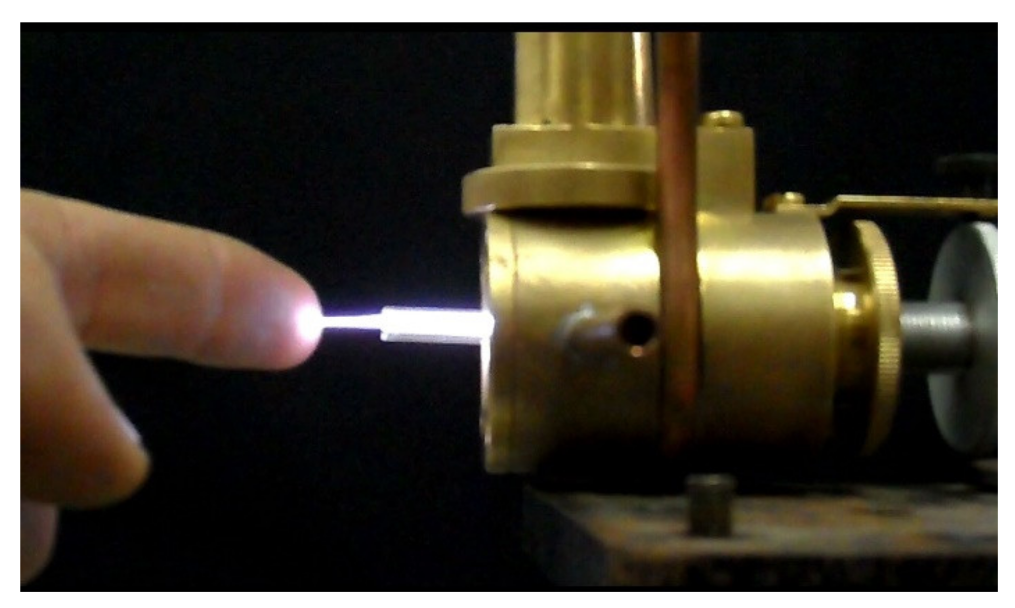
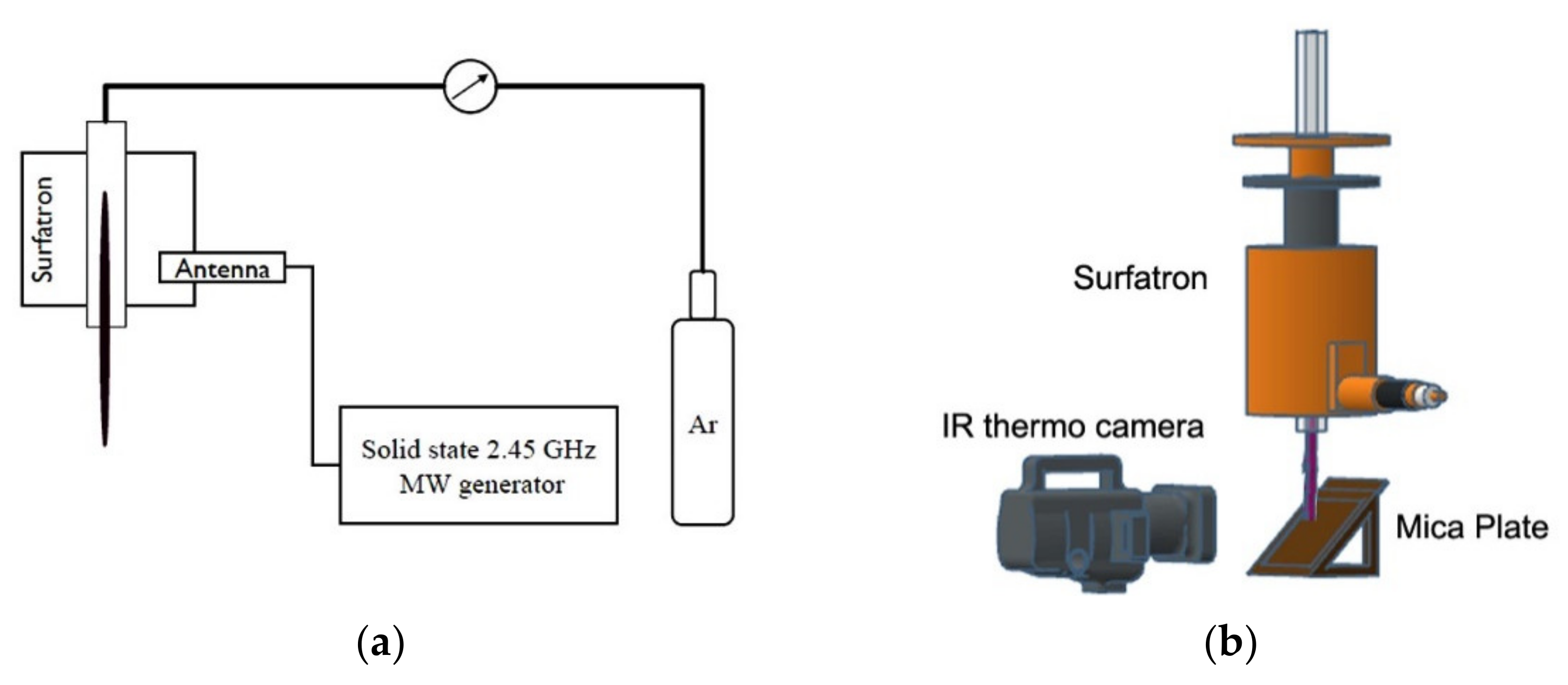
2.1. Experimental

The experimental set-up is schematically presented in Figure 2a. A simple surfatron-type wave launcher is used for plasma sustaining. The surfatron (Sairem, SURFATRON 80) is connected with a solid-state microwave generator at 2.45 GHz (Sairem, GMS 200 W) by a coaxial cable. The plasma is produced inside the discharge tube situated at the surfatron axis. Various quarts tubes with different outer and inner diameters (Table 1) are used. For all of them, the real and imaginary parts of the dielectric permittivity are εr = 5.58 and εi = 0.036, respectively. The discharge tubes end is fixed at 2 mm out of the surfatron, and the plasma torch is formed out of the discharge tube in the air. The working gas is argon 5.0 (purity of 99.999%), and its mass flow is controlled by Omega FMA-A2408 mass flow controller. The system is vertically installed with the gas flow from top to down.
As it was mentioned above, the propagating surface wave produces strongly non-equilibrium plasma not only at low and intermediate, but also at atmospheric pressure. Under such conditions, the assumption that the translational (gas) temperature is equal to the rotational temperature cannot be used a priori. This is shown for other types of non-equilibrium discharges in [45] and discussed in detail in [46]. Approaching carefully this problem, it is shown in [25] that the rotational temperatures calculated from the nitrogen second positive 0–2 band is in the interval 1500–3000 K, while it is between 600 K and 1000 K when using the OH (A → X) 0–0 band. No information about the gas temperature of the plasma torch is obtained in this way. In [25], the maximum temperature on the treated sample (fresh pork skin, 10 s treatment) measured by a thermo camera when the plasma torch tip touches the sample is about 110–120 °C. Although the area on the sample surface with such a temperature is very small and the average temperature is lower, such conditions are not acceptable for bio-medical applications.
It is also observed that around the plasma filament in the discharge tube, there exists hot argon gas, which flows outside close to the plasma torch. Its temperature is usually higher than that of the plasma torch, but it does not radiate in the visible region and is not registered by optical emission spectroscopy.
Because of the above reasons, the plasma temperature is obtained by two independent methods: contact thermometry at the plasma tip and via thermal emission measured by Mica Plate and an infrared thermo camera system. (Figure 2b). The used contact thermometer is a mercury thermometer with fused quartz with a range of up to 400 °C. The temperature determined in this way is the average temperature of the plasma column and of the gas surrounding the plasma at the position where the treated sample usually is placed.
We used a Testo 865 thermal imager for the infrared thermography of a standard Mica Plate inclined at 45 degrees to the plasma torch axis and the camera-to-plate center direction. The distance between the plasma column end and Mica Plate was 29 cm and distance of the camera–plate was 55 cm. The ambient temperature was 21 °C, and the relative humidity was 48%. The method of infrared thermography determined the average plasma jet temperature, ignoring the carrying gas temperature.
Microwave radiation measurements from the Surfatron device were done by half-wave dipolar antenna attached to HF ANALYSER HF59B by Gigahertz Solutions® or wattmeter Я2M-66. Measurements were done with use of 20 dB attenuator and antenna at the level of the plasma column end.

2.2. Modeling

The surface-wave discharge plasma is sustained by an electromagnetic wave propagating along the plasma–dielectric interface in a waveguide structure, including also the sustained plasma. This requires a self-consistent model for describing the wave–plasma system. The self-consistent model includes a kinetic part describing the elementary processes inside the plasma and an electrodynamic part for the wave propagation based on Maxwell’s equations. These two parts are linked in a self-consistent way by the energy balance equations of the electromagnetic wave and the electrons in each point along the plasma torch because the plasma is axially inhomogeneous. The self-consistent approach used in this paper is schematically presented in Figure 3.
The main equations in the electrodynamic part are the local dispersion equation and the wave energy balance equation obtained from Maxwell’s equations. The kinetic part is based on the electron Boltzmann equation together with the electron energy balance equation and the particle balance equations for electrons, ions and excited atoms. The kinetic model of the surface-wave-sustained argon plasma at atmospheric pressure is presented in detail in [47].

3. Results

The modeling allows obtaining the plasma and wave characteristics by varying the discharge condition parameters, such as the tube size, its dielectric permittivity and the wave frequency. The plasma goes out of the discharge tube, forming the plasma torch in the open space, where the electromagnetic wave continues its propagation along the plasma–air interface. In this way, the region of the plasma torch is a region of active plasma sustained by the electromagnetic field of the wave.

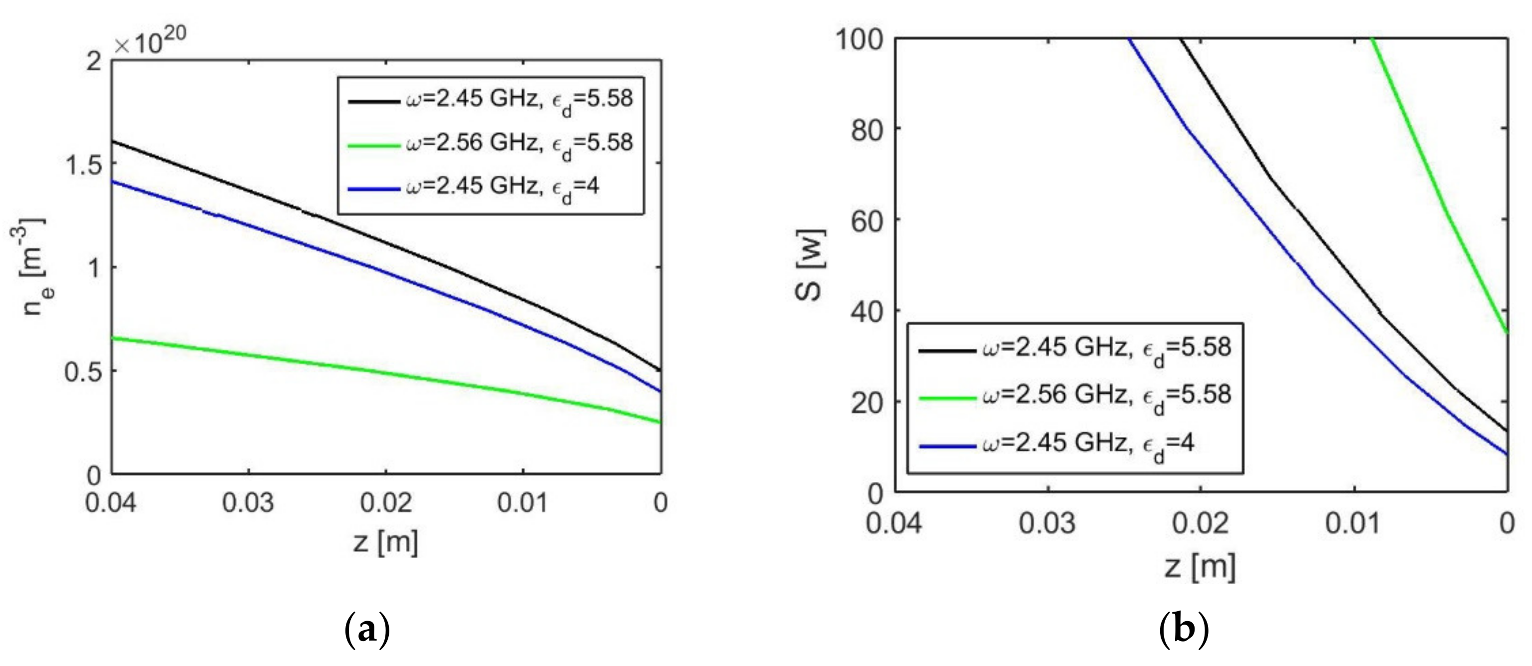
3.1. Effects of the Dielectric Tube Permittivity and the Wave Frequency

The dielectric permittivity is one of the important characteristics of the discharge tube, which is a part of the waveguide structure for the wave propagation. Using different materials for the discharge tube, one can obtain higher or lower plasma density and temperature at the same geometry parameters and wave power. Figure 4 illustrates the changes in the plasma density (electron number density) ne and the wave power axial distributions at two different dielectric permittivity values (εd = 4 and 5.58) of the same size discharge tube (8 mm/2 mm, see Table 1). For easily comparing the results, the end of the plasma torch is at position z = 0, and the surfatron position is on the left side of the graph. The well-known almost linear axial distribution of the plasma density is confirmed for all discharge conditions. The effect of the dielectric permittivity increasing is in the increasing in the plasma density, but it is not very significant.
The increase in the wave frequency turns out to produce a much more visible result in decreasing the plasma density combined with increasing the wave power necessary for its sustaining. This is seen in comparison with the black and green curves in Figure 4.

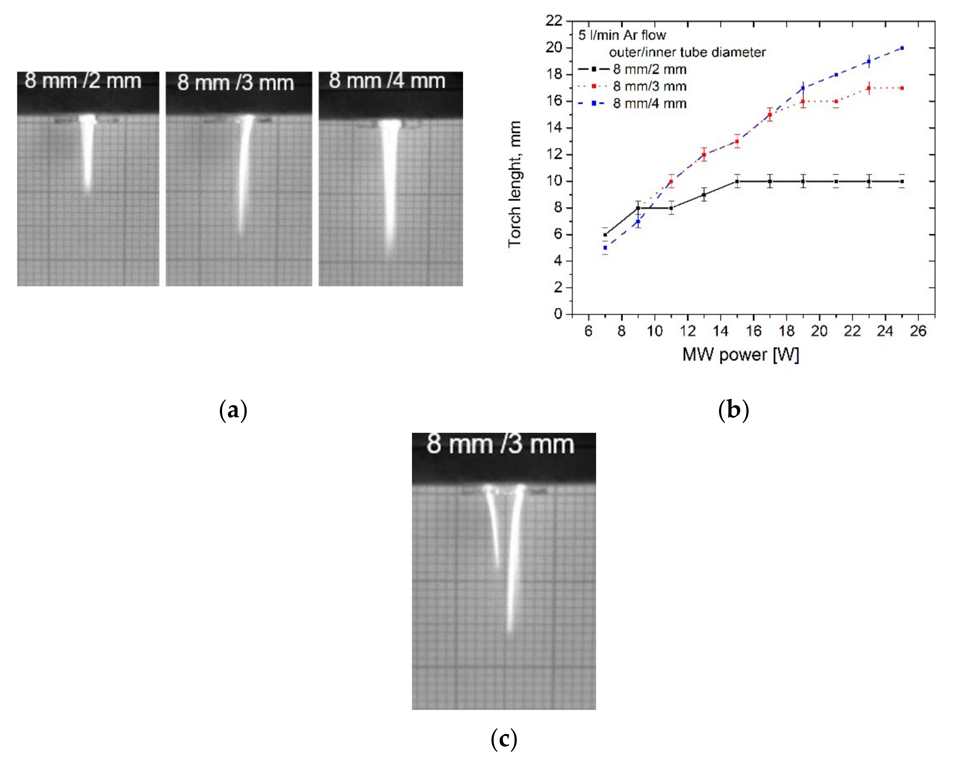
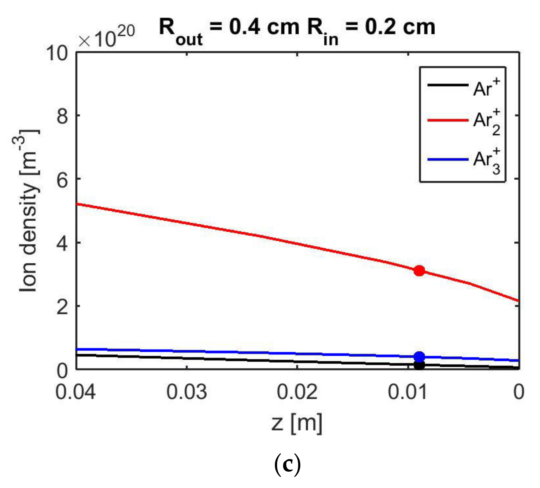
3.2. Effects of the Dielectric Tube Inner Diameter on the Plasma Column Size

The axial distribution of the plasma density ne obtained theoretically for the three discharge tubes 8/2, 8/3 and 8/4 (see Table 1) is presented in Figure 5a—solid lines. The plasma torch where plasma is surrounded by air is presented by dashed lines. The corresponding wave power can be seen in Figure 5b. The length of the plasma torch also increases with the wave power. The torch length produced with the same wave power (100 W) is marked by dots in Figure 5a. One can see that the theoretical prediction obtains a longer plasma column with a higher plasma density at the same wave power in the discharge tube with the smaller inner radius. Respectively, the plasma column with the same length is produced in the discharge tube with a smaller inner radius by a lower wave power. The plasma torch is longer, but with a lower electron density compared to the plasma inside the dielectric tube with the same wave power. From Figure 5b, one can see also that at the end of the plasma column inside the dielectric tube, the microwave power is not completely absorbed, and the residual power is higher at a smaller internal tube radius. At the end of the plasma torch (dashed lines), the residual microwave power is much lower.
The experimentally measured plasma torch length produced by using the three discharge tubes shows different behavior. In Figure 6a, the fast camera imaging of the plasma torches in the three tubes are presented. From such images, the plasma torch length is measured at a different wave power, and the graphs are presented in Figure 6b. At the same wave power, the longer plasma torch is obtained in the discharge tube with the bigger internal radius, which is just the opposite to the theoretical results. There are two reasons for such discrepancy: (i) in the modeling, the gas flow is neglected, while all experiments are in the gas flow regime, and the gas glow varies from 2 L/min to 15 L/min. The experimental results presented in Figure 6b are at a gas flow rate of 5 L/min. (ii) The model results are obtained under the assumptions that the discharge tube is completely filled with plasma (or the plasma torch radius is equal to the discharge tube radius), while the experiment shows that inside the tube, there exist one or more filaments. Initially, at a low wave power, the filament is only one in each tube, but does not fill the tube completely in the radial direction. With wave power, the increasing of the length of the filament is almost linear, as it is theoretically predicted, but at some power, depending on the tube inner radius, a second filament appears, and the length of the first one stops increasing. This is illustrated in Figure 6c for the 8 mm/3 mm discharge tube. Our investigation shows that the appearance of the second filament happens at a lower wave power when the inner diameter of the discharge tube is smaller. It is shown by experimental [48] and radial modeling [49] investigations that the molecular argon ions play a critical role in the radial contraction of argon microwave discharges at atmospheric pressure. Our modeling results show the axial distribution of argon atomic (Ar+) and two molecular (Ar2+ and Ar3+) ions along the plasma column in the three discharge tubes (Figure 7). As it can be seen, the molecular Ar2+ ion has a much higher concentration than the other two ions in all tubes, which is in good agreement with the prediction in [48,49]. The highest concentration of Ar2+ ion is in the tube with the smaller inner diameter (8 mm/2 mm). This can be the reason for the fast formation of the second filament at a lower wave power in this tube, but further investigations would be needed to explain it.
These experimental results show also that even at a low wave power, the length of the plasma torches in all tubes is enough for the direct treatment of the samples. The important question for bio-medical applications is what the temperature at the position of the samples is so that thermal damage is avoided.

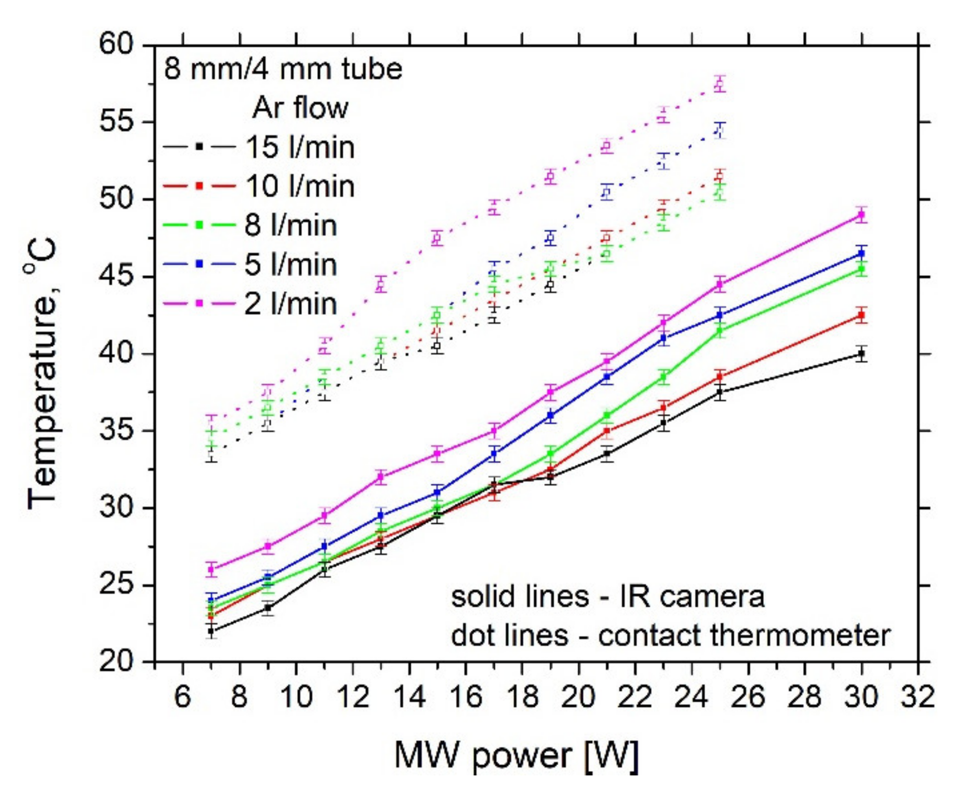
3.3. Temperature at the Sample Position

For this investigation, the argon flow rate is varied from 2 L/min to 15 L/min for the three tubes. The temperature is measured by a contact thermometer and by the Mica Plate and infrared thermo camera system. Figure 8 illustrates the latter experiments and obtained images used for the temperature estimation at an argon flow rate of 10 L/min. Similar images are obtained at all the other discharge conditions.
Figure 9 demonstrates the effect of the discharge tube inner diameter on the temperature at fixed gas flow rate. In Figure 9a, the gas flow rate is 5 L/min and in Figure 9b it is twice higher, 10 L/min. The temperature measured by the contact thermometer is always higher than that obtained by the IR camera. We observe that the temperature of the plasma is lower than the temperature of the not ionized Argon in the tube and ambient gas outside it. By the contact thermometer, the average temperature of the plasma and ambient gas is measured, while infrared thermography determines only the average plasma temperature, ignoring the carrying gas temperature.
Both methods show that the lower temperature is obtained by using the discharge tube with a bigger inner diameter, i.e., 8 mm/4 mm. For this tube, even at 20 W wave power, the temperature does not exceed 45 °C, measured by the contact thermometer. Similar results are obtained for all the other gas flow rates, i.e., the best performance is shown for the 8 mm/4 mm discharge tube. More detailed dependance of the temperature on the gas flow rate for the 8/4 discharge tube is shown in Figure 10.
At a higher gas flow rate, the temperature is lower, but this effect is less than 5 °C at a low wave power and less than 10 °C at 30 W. Comparing the results presented in Figure 9 and Figure 10, one can conclude that for decreasing the temperature at the sample, it is more important to choose a discharge tube with a bigger inner diameter than to increase the gas flow and gas consumption. In addition, if the sample is solid, its surface is not much affected by the high gas flow, but this is not the case when the treated sample is liquid. In the latter case, the gas flow cannot be too high. For the discharge tube of 8 mm/4 mm, the temperature below 45 °C can be achieved by a gas flow rate of 5 L/min or 8 L/min at a wave power of up to 20 W, which could be the optimal operational regime.

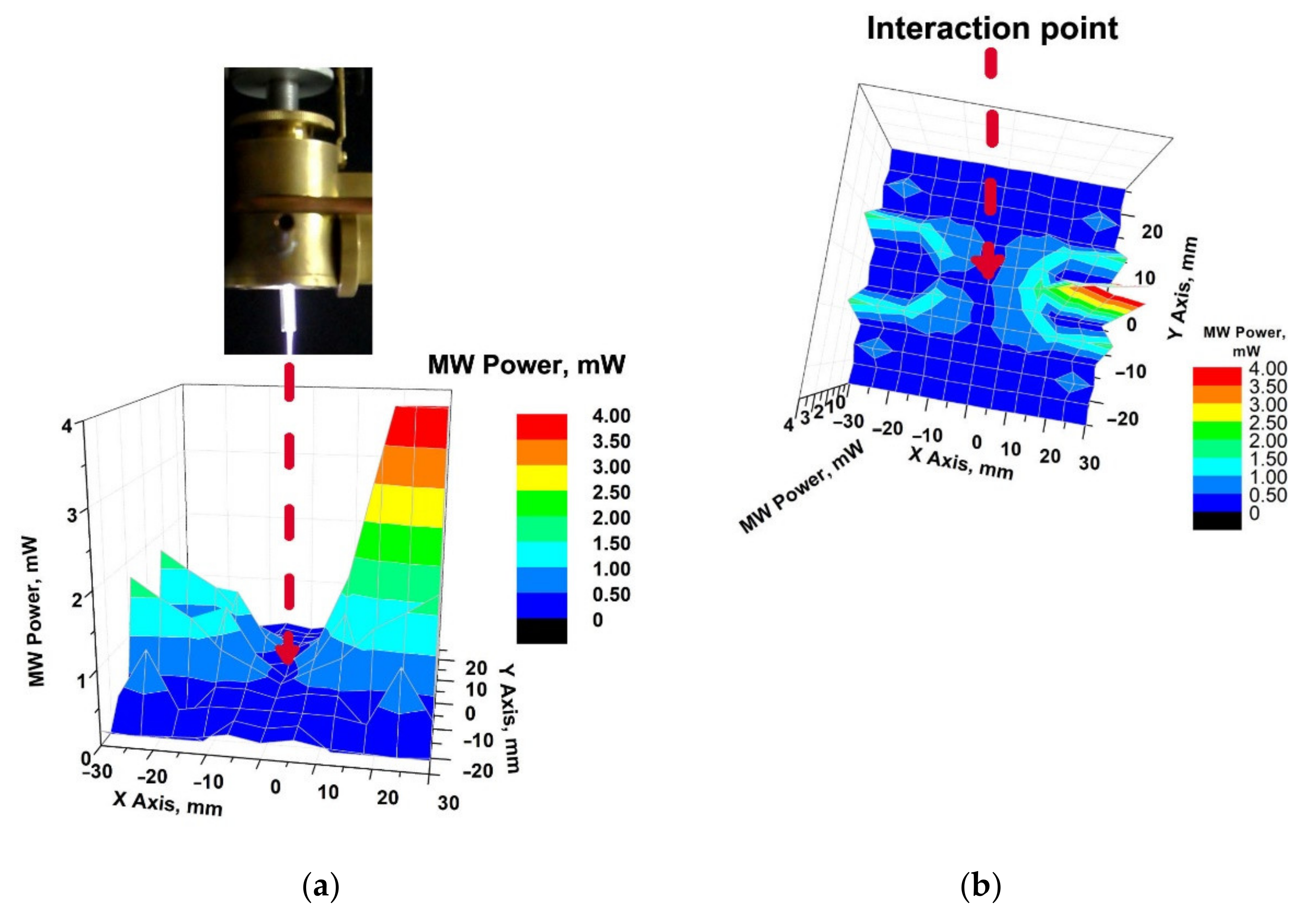
3.4. Microwave Radiation at the Sample Position

One of the reasons for not widely using the SWD at atmospheric pressure for bio-medical purposes is its operation at 2.45 GHz and the possible residual microwave power at the torch end and treatment sample position. The possible microwave radiation on the biological systems can produce unwanted and unacceptable biological effects. Although for SWD, the wave power is well absorbed by the plasma and usually the reflected power is less than 1 W, this problem requires special attention. The microwave radiation distribution around the sample position is illustrated in Figure 11 at typical discharge conditions. The results show that at all discharge conditions, the microwave radiation at the sample position is from 0.3 mW to 0.45 mW. Thus, we cannot expect any negative effect from the MW radiation on the biological systems due to the plasma treatment. The highest level of microwave radiation (4–5 mW) is at the connection of the surfatron antenna to the coaxial cable. This problem can be easily solved by shielding this region, which will not disturb the sample treatment.

4. Discussion

The results obtained show that the plasma characteristics of the surface-wave-sustained argon plasma torch operating at 2.45 GHz can be easily optimized to meet the requirements for bio-medical applications. For such applications, the operation regime is at a low wave power. With increasing the wave power, the length of the plasma torch increases. It is usually assumed for SWD that the increase in the wave power leads to the addition of a new part of the plasma column close to the wave exciter but without changing the plasma properties already produced by the lower power part near the plasma column end. This is correct for SWD at low pressure, but this investigation shows that at atmospheric pressure, the temperature at the same distance from the column end increases with the wave power. In order to keep the temperature below 45 °C, it is necessary to work at a low wave power (to about 30 W) regime of operation. It is good to keep the wave power as low as possible in order to avoid thermal damage to the sample.
Another important parameter than can be varied for decreasing the temperature is the discharge tube size. The temperature is lower when the inner diameter of the tube is bigger. For our tubes with an outer diameter of 8 mm, the temperatures lower than 45 °C are obtained at inner diameters of 4 mm and 3 mm at the wave power that can be increased up to 30 W. The temperature at the same position of the plasma in the tube with an inner diameter of 2 mm can be below 45 °C only at a wave power lower than 10 W.
The argon flow rate is another parameter that can be varied for decreasing the temperature. With increasing the gas flow rate, the temperature decreases. However, this decrease is not as significant as expected. Increasing the argon flow rate from 2 L/min to 15 L/min leads to a decrease in the temperature of about 10 °C at high wave power and even less at low wave power. Additional problems are the high gas consumption, affecting the soft surfaces during the treatment by the high gas flow. That is why the optimal operational regime is at a gas flow rate from 5 L/min to 8 L/min at the given discharge tubes of 8 mm/4 mm and 8 mm/3 mm.
The measurements show that problem with microwave radiation on the treated sample is not significant under the low wave power operational conditions. At the sample position, the microwave 2.45 GHz radiation does not exceed 0.4 mW. The radiation up to 4 mW that appears at the connection of the coaxial cable with the surfatron antenna can be easily shielded without disturbing the sample treatment.

5. Conclusions

The results obtained show that the surface-wave-sustained argon plasma torch operating at atmospheric pressure can keep the temperature at the treated sample surface below 45 °C, which is one of the main requirements for using this plasma for in vivo and in vitro treatment in biology, medicine and agriculture. By choosing a discharge tube with bigger inner diameter, varying the working gas flow rate and keeping low enough microwave power, the optimal regime of operation with low temperature can be achieved. At a low wave power regime, the microwave radiation at the sample position does not exceed 0.4 mW and does not affect the treated sample. All obtained results show that the microwave plasma torch fulfills the requirements to be successfully used for bio-medical applications.

Author Contributions

The investigations concept was proposed during personal discussion between all authors. The modeling approach and conditions were proposed by E.B. and P.M. The modeling results were prepared by P.M. Contact measurement of plasma column temperature, T.B., I.T., R.T.-H., Z.S. and N.V.; infrared thermography, T.B., I.T., T.H., D.B. and L.T.; measurement of radiated electromagnetic field, T.B., T.H. and L.T. The manuscript writing was done by E.B., T.B. and P.M. All authors have read and agreed to the published version of the manuscript.

Funding

This research was funded by the Grant No. BG05M2OP001-1.002-0019: “Clean Technologies for Sustainable Environment-Waters, Waste, Energy for a Circular Economy”, financed by the Science and Education for Smart Growth Operational Program (2014-2020) and co-financed by the EU through the ESIF.

Institutional Review Board Statement

Not applicable.

Informed Consent Statement

Not applicable.

Data Availability Statement

The data that support the presented results of this study are available from the corresponding author upon reasonable request.

Conflicts of Interest

The authors declare no conflict of interest.

References

  1. Weltmann, K.-D.; von Woedtke, T. Plasma medicine—Current state of research and medical application. Plasma Phys. Control. Fusion 2017, 59, 014031. [Google Scholar] [CrossRef]
  2. Park, G.Y.; Park, S.J.; Choi, M.Y.; Koo, I.G.; Byun, J.H.; Hong, J.W.; Sim, J.Y.; Collins, G.J.; Lee, J.K. Atmospheric-pressure plasma sources for biomedical applications. Plasma Sources Sci. Technol. 2012, 21, 043001. [Google Scholar] [CrossRef]
  3. Isbary, G.; Shimizu, T.; Li, Y.-F.; Stolz, W.; Thomas, H.M.; Morfill, G.E.; Zimmermann, J.L. Cold atmospheric plasma devices for medical issues. Expert Rev. Med. Devices 2013, 10, 367–377. [Google Scholar] [CrossRef] [PubMed]
  4. Kong, M.G.; Kroesen, G.; Morfill, G.; Nosenko, T.; Shimizu, T.; van Dijk, J.; Zimmermann, J.L. Plasma medicine: An introductory review. New. J. Phys. 2009, 11, 115012. [Google Scholar] [CrossRef]
  5. Laroussi, M. Low-Temperature Plasma Jet for Biomedical Applications: A Review. IEEE Trans. Plasma Sci. 2015, 43, 703–712. [Google Scholar] [CrossRef]
  6. Laroussi, M.; Bekeschus, S.; Keidar, M.; Bogaerts, A.; Fridman, A.; Lu, X.-P.; Ostrikov, K.; Hori, M.; Stapelmann, K.; Miller, V.; et al. Low Temperature Plasma for Biology, Hygiene, and Medicine: Perspective and Roadmap. IEEE Trans. Radiat. Plasma Med. Sci. 2021. [Google Scholar] [CrossRef]
  7. Laroussi, M. Cold Plasma in Medicine and Healthcare: The New Frontier in Low Temperature Plasma Applications. Front. Phys. 2020, 8, 74. [Google Scholar] [CrossRef]
  8. Simek, M.; Homola, T. Plasma-assisted agriculture: History, presence, and prospects—A review. Eur. Phys. J. D 2021, 75, 210. [Google Scholar] [CrossRef]
  9. Sonawane, S.K.; Marar, T.; Sonal, P. Non-thermal plasma: An advanced technology for food industry. Food Sci. Technol. Int. 2020, 26, 727–740. [Google Scholar] [CrossRef]
  10. Misra, N.N.; Schluter, O.; Cullen, P.J. (Eds.) Cold Plasma in Food and Agriculture; Elsevier: Amsterdam, The Netherlands, 2016. [Google Scholar]
  11. Morrison, C.F., Jr. Electrosurgical Method and Apparatus for Initiating an Electrical Discharge in an Inert Gas Flow. U.S. Patent 4040426, 9 August 1977. [Google Scholar]
  12. Farin, G.; Grund, K.E. Technology of argon plasma coagulation with particular regard to endoscopic applications. Endoscop. Surg. Allied Technol. 1994, 2, 71–77. [Google Scholar]
  13. Romero-Mangado, J.; Dey, A.; Diaz-Cartagena, D.C.; Solis-Marcano, N.E.; Lopez-Nieves, M.; Santiago-Garcia, V.; Nordlund, D.; Krishnamurthy, S.; Meyyappan, M.; Koehne, J.E.; et al. Efficacy of atmospheric pressure dielectric barrier discharge for inactivating airborne pathogens. J. Vac. Sci. Technol. 2017, A35, 041101. [Google Scholar] [CrossRef] [Green Version]
  14. Kuzminova, A.; Kretková, T.; Kylián, O.; Hanuš, J.; Khalakhan, I.; Prukner, V.; Doležalová, E.; Šimek, M.; Biederman, H. Etching of polymers, proteins and bacterial spores by atmospheric pressure DBD plasma in air. J. Phys. D Appl. Phys. 2017, 50, 135201. [Google Scholar] [CrossRef]
  15. Babaeva, N.Y.; Kushner, M.J. Dynamics of dielectric barrier discharges over wounded skin. IEEE Trans. Plasma Sci. 2011, 39, 2964–2965. [Google Scholar] [CrossRef] [Green Version]
  16. Isbary, G.; Zimmermann, J.L.; Shimizu, T.; Li, Y.-F.; Morfill, G.E.; Thomas, H.M.; Steffes, B.; Heinlin, J.; Karrer, S.; Stolz, W. Non-thermal plasma—More than five years of clinical experience. Clin. Plasma Med. 2013, 1, 19–23. [Google Scholar] [CrossRef]
  17. Fridman, A.; Chirokov, A.; Gutsol, A. Non-thermal atmospheric pressure discharges. J. Phys. D Appl. Phys. 2005, 38, R1–R24. [Google Scholar] [CrossRef]
  18. Von Woedtkea, T.; Reuter, S.; Masura, K.; Weltmann, K.-D. Plasmas for medicine. Phys. Rep. 2013, 530, 291–320. [Google Scholar] [CrossRef]
  19. Reuter, S.; Von Woedtke, T.; Weltmann, K.-D. The kINPen—A review on physics and chemistry of the atmospheric pressure plasma jet and its applications. J. Phys. D Appl. Phys. 2018, 51, 233001. [Google Scholar] [CrossRef] [Green Version]
  20. Foest, R.; Kindel, E.; Lange, H.; Ohl, A.; Stieber, M.; Weltmann, K.D. RF capillary jet—A tool for localized surface treatment. Contrib. Plasma Phys. 2007, 47, 119–128. [Google Scholar] [CrossRef]
  21. Fricke, K.; Steffen, H.; Von Woedtke, T.; Schroder, K.; Weltmann, K.D. High rate etching of polymers by means of an atmospheric pressure plasma jet. Plasma Process. Polym. 2011, 8, 51–58. [Google Scholar] [CrossRef]
  22. Jablonowski, L.; Fricke, K.; Matthes, R.; Holtfreter, B.; Schluter, R.; Von Woedtke, T.; Weltmann, K.D.; Kocher, T. Removal of naturally grown human biofilm with an atmospheric pressure plasma jet: An In Vitro study. J. Biophotonics 2016, 10, 718–726. [Google Scholar] [CrossRef] [PubMed] [Green Version]
  23. Arndt, S.; Schmidt, A.; Karrer, S.; Von Woedtke, T. Comparing two different plasma devices kINPen and Adtec SteriPlas regarding their molecular and cellular effects on wound healing. Clin. Plasma Med. 2018, 9, 24–33. [Google Scholar] [CrossRef]
  24. Benova, E.; Topalova, Y.; Marinova, P.; Todorova, Y.; Atanasova, M.; Bogdanov, T.; Yotinov, I. Surface-wave-sustained plasma for model biological systems treatment. In Proceedings of the XXXIII International Conference on Phenomena in Ionized Gases (ICPIG), Estoril, Portugal, 9–14 July 2017; Alves, L.L., Tejero-del-Caz, A., Eds.; Instituto de Plasmas e Fusão Nuclear, Instituto Superior Técnico, Universidade de Lisboa: Lisboa, Portugal, 2017. Topic Number: 17. p. 87. [Google Scholar]
  25. Krčma, F.; Tsonev, I.; Smejkalová, K.; Truchlá, D.; Kozáková, Z.; Zhekova, M.; Marinova, P.; Bogdanov, T.; Benova, E. Microwave micro torch generated in argon based mixtures for biomedical applications. J. Phys. D Appl. Phys. 2018, 51, 414001. [Google Scholar] [CrossRef]
  26. Tsvetkov, V.; Hinkov, A.; Todorov, D.; Benova, E.; Tsonev, I.; Bogdanov, T.; Shishkov, S.; Shishkova, K. Effect of Plasma-Activated Medium and Water on Replication and Extracellular Virions of Herpes Simplex Virus-1. Plasma Med. 2019, 9, 205–216. [Google Scholar] [CrossRef]
  27. Bogdanov, T.; Tsonev, I.; Traikov, L.L. Microwave plasma torch for wound treatment. J. Phys. Conf. Ser. 2020, 1598, 012001. [Google Scholar] [CrossRef]
  28. Milusheva, S.; Nacheva, L.; Benova, E.; Marinova, P.; Dimitrova, N.; Georgieva-Hristeva, A. Experiments on Plum pox virus inactivation from micropropagated plum plants through non-thermal plasma treatment. Plant Prot. Bull. 2020, 60, 83–90. [Google Scholar]
  29. Nedyalkova, S.; Bozhanova, V.; Benova, E.; Marinova, P.; Tsonev, I.; Bogdanov, T.; Koleva, M. Study on the Effect of Cold Plasma on the Germination and Growth of Durum Wheat Seeds Contaminated with Fusarium Graminearum. Int. J. Innov. Approaches Agric. Res. 2019, 3, 623–635. [Google Scholar] [CrossRef]
  30. Bogdanov, T.; Tsonev, I.; Marinova, P.; Benova, E.; Rusanov, K.; Rusanova, M.; Atanassov, I.; Kozáková, Z.; Krčma, F. Microwave Plasma Torch Generated in Argon for Small Berries Surface Treatment. Appl. Sci. 2018, 8, 1870. [Google Scholar] [CrossRef] [Green Version]
  31. Moisan, M.; Beaudry, C.; Leprince, P. A new HF device for the production of long plasma columns at a high electron density. Phys. Lett. 1974, 55A, 125–126. [Google Scholar] [CrossRef]
  32. Moisan, M.; Beaudry, C.; Leprince, P. A small microwave plasma source for long column production without magnetic field. IEEE Trans. Plasma Sci. 1975, 3, 55–59. [Google Scholar] [CrossRef]
  33. Moisan, M.; Leprince, P.; Beaudry, C.; Bloyet, E. Devices and Methods of Using HF Wave to Energize a Column of Gas Enclosed in an Insulating Casing. U.S. Patent No. 4049940, 20 September 1977. [Google Scholar]
  34. Zakrzewski, Z.; Moisan, M.; Glaude, V.M.M.; Beaudry, C.; Leprince, P. Attenuation of a surface wave in an unmagnetized RF plasma column. Plasma Phys. 1977, 19, 77–83. [Google Scholar] [CrossRef]
  35. Moisan, M.; Zakrzewski, Z.; Pantel, R. The theory and characteristics of an efficient surface wave launcher (surfatron) producing long plasma columns. J. Phys. D Appl. Phys. 1979, 12, 219–237. [Google Scholar] [CrossRef]
  36. Zhelyazkov, I.; Atanassov, V. Axial structure of low-pressure high-frequency discharges sustained by travelling electromagnetic surface waves. Phys. Rep. 1995, 255, 79–201. [Google Scholar] [CrossRef]
  37. Moisan, M.; Nowakowska, H. Contribution of surface-wave (SW) sustained plasma columns to the modeling of RF and microwave discharges with new insight into some of their features. A survey of other types of SW discharges. Plasma Sources Sci. Technol. 2018, 27, 073001. [Google Scholar] [CrossRef]
  38. Petrova, T.; Benova, E.; Petrov, G.; Zhelyazkov, I. Self-consistent axial modeling of surface-wave-produced discharges at low and intermediate pressures. Phys. Rev. E 1999, 60, 875–886. [Google Scholar] [CrossRef] [PubMed] [Green Version]
  39. Moisan, M.; Pantel, R.; Hubert, J.; Bloyet, E.; Leprince, P.; Marec, J.; Ricard, A. Production and Applications of Microwave Surface Wave Plasma at Atmospheric Pressure. J. Microw. Power 1979, 14, 57–61. [Google Scholar] [CrossRef]
  40. Al-Shamma’a, A.I.; Wylie, S.R.; Lucas, J.; Pau, C.F. Design and construction of a 2.45 GHz waveguide-based microwave plasma jet at atmospheric pressure for material processing. J. Phys. D Appl. Phys. 2001, 34, 2734–2741. [Google Scholar] [CrossRef]
  41. Uhm, H.S.; Kwak, H.S.; Hong, Y.C. Carbon dioxide elimination and regeneration of resources in a microwave plasma torch. Environ. Pollut. 2016, 211, 191–197. [Google Scholar] [CrossRef] [PubMed]
  42. Uhm, H.S.; Hong, Y.C.; Shin, D.H. Microwave plasma torch and its applications. Plasma Sources Sci. Technol. 2006, 15, S26–S34. [Google Scholar] [CrossRef]
  43. Castanos-Martiınez, E.; Moisan, M.; Kabouzi, Y. Achieving non-contracted and non-filamentary rare-gas tubular discharges at atmospheric pressure. J. Phys. D Appl. Phys. 2009, 42, 012003. [Google Scholar] [CrossRef]
  44. Henriques, J.; Tatarova, E.; Ferreira, C.M. Microwave N2–Ar plasma torch. J. Appl. Phys. 2011, 109, 023301. [Google Scholar] [CrossRef]
  45. Bruggeman, P.; Schram, D.C.; Kong, M.G.; Leys, C.H. Is the Rotational Temperature of OH(A–X) for Discharges in and in Contact with Liquids a Good Diagnostic for Determining the Gas Temperature? Plasma Process. Polym. 2009, 6, 751–762. [Google Scholar] [CrossRef]
  46. Bruggeman, P.J.; Sadeghi, N.; Schram, D.C.; Linss, V. Gas temperature determination from rotational lines in non-equilibrium plasmas: A review. Plasma Sources Sci. Technol. 2014, 23, 023001. [Google Scholar] [CrossRef] [Green Version]
  47. Benova, E.; Marinova, P.; Atanasova, M.; Petrova, T.Z. Surface-wave-sustained argon plasma kinetics from intermediate to atmospheric pressure. J. Phys. D Appl. Phys. 2018, 51, 474004. [Google Scholar] [CrossRef]
  48. Ridenti, M.A.; Spyrou, N.; Amorim, J. The crucial role of molecular ions in the radial contraction of argon microwave-sustained plasma jets at atmospheric pressure. Chem. Phys. Lett. 2014, 595–596, 83–86. [Google Scholar] [CrossRef]
  49. Ridenti, M.A.; Amorim, J.; Pino, A.D. Causes of plasma column contraction in surface-wave-driven discharges in argon at atmospheric pressure. Phys. Rev. E 2018, 97, 013201. [Google Scholar] [CrossRef] [PubMed] [Green Version]
Figure 1. Plasma torch produced by a surfatron wave launcher.
Applsci 12 00969 g001
Figure 2. Experimental set-up: (a) surface-wave sustained argon plasma torch; (b) Mica Plate and infrared thermo camera system.
Applsci 12 00969 g002
Figure 3. Schematic of self-consistent modeling approach.
Applsci 12 00969 g003
Figure 4. Theoretical axial distribution for the discharge tube 8 mm/2 mm at different discharge conditions of (a) plasma density; (b) wave power.
Applsci 12 00969 g004
Figure 5. Theoretical axial distribution for three discharge tubes with different internal radii of (a) plasma density; (b) wave power. The solid lines correspond to plasma inside dielectric tube and the dashed lines are for plasma torch (plasma surrounded by air).
Applsci 12 00969 g005
Figure 6. (a) Fast camera images of the plasma torch in the three tubes. (b) Experimental results for the plasma torch length in the three tubes. (c) Appearance of a second filament at higher wave power for 8 mm/3 mm tube.
Applsci 12 00969 g006
Figure 7. Axial distribution of argon atomic ion Ar+ (balck lines) and two molecular ions Ar2+ (red lines) and Ar3+ (blue lines) along the plasma column in the three discharge tubes: (a) 8 mm/2 mm; (b) 8 mm/3 mm; (c) 8 mm/4 mm. The dots correspond to the same wave power as in Figure 5a.
Applsci 12 00969 g007aApplsci 12 00969 g007b
Figure 8. Images from Mica Plate and infrared thermo camera system.
Applsci 12 00969 g008
Figure 9. Temperature measured at the position of the sample as function of the wave power for three inner diameters of the discharge tubes. Solid symbols and lines are the results obtained by the IR camera and the empty symbols and dot lines by contact thermometer. The argon flow rate is fixed at (a) 5 L/min; (b) 10 L/min.
Applsci 12 00969 g009
Figure 10. Effect of argon flow rate on the temperature for 8 mm/4 mm discharge tube.
Applsci 12 00969 g010
Figure 11. Microwave radiation distribution around the sample position at wave frequency 2.45 GHz, wave power 9 W, reflected power less than 1 W, discharge tube 8/3, argon flow 7 L/min: (a) side view; (b) top view.
Applsci 12 00969 g011
Table 1. Outer and inner diameters of quarts tubes used.
Tube NotationOuter Diameter Inner Diameter
8/28 mm2 mm
8/38 mm3 mm
8/48 mm4 mm
Publisher’s Note: MDPI stays neutral with regard to jurisdictional claims in published maps and institutional affiliations.

