Article

Solid-State Transformer-Based DC Power Distribution Network for Shipboard Applications

1
Department of Electrical Engineering, Alexandria University, Alexandria 21544, Egypt
2
Smart-CI Center, Alexandria University, Alexandria 21544, Egypt
3
Department of Electrical and Control Engineering, Arab Academy for Science, Technology and Maritime Transport, Alexandria 21913, Egypt
4
CEMSE Division at King Abdullah University of Science and Technology, Thuwal 23955, Saudi Arabia
5
Department of Marine Engineering Technology, Arab Academy for Science, Technology and Maritime Transport, Alexandria 21913, Egypt
*
Author to whom correspondence should be addressed.
Appl. Sci. 2022, 12(4), 2001; https://doi.org/10.3390/app12042001
Submission received: 30 January 2022 / Revised: 9 February 2022 / Accepted: 10 February 2022 / Published: 14 February 2022
(This article belongs to the Topic Advanced Systems Engineering: Theory and Applications)

Abstract

:
Due to simplicity, efficiency, and the ability to accommodate energy storage devices, DC distribution networks have been seen as an optimal alternative to AC distribution networks, especially aboard future electric ships. The emerging distribution DC system entails new control and management techniques. Therefore, an integrated DC power distribution network aboard an electric ship is selected as the case study in this paper. To meet the requirements of such a large-scale mobile power system, a multiport solid-state transformer (SST) based on silicon carbide (SiC) switches/MOSFETs is proposed. Thus, the system embodiment can significantly be reduced. Moreover, at the DC distribution level, a high penetration of renewable generation with energy storage is allowed and a six-phase asymmetrical induction machine (IM) can directly be integrated. Simulations have been conducted based on a 2 MW shipboard distribution network. The effects of the propulsion system dynamics on the SST are highlighted as well. Finally, a 2 kW lab-scale prototype has been implemented to validate the theoretical findings.

1. Introduction

Marine vessel electrification has been gaining interest due to the growing onboard power demand along with the restricted design rules. Currently, several low-voltage electric ships are commercially available, with a future trend towards the medium voltage ones [1,2,3,4,5]. According to the marine regulations, 1 kV is considered as a low voltage level used on most shipboards, whereas 3.3 kV and 6.6 kV commonly represent the standard high voltage levels. Electric ship propulsion has recently been recognized as the most efficient propulsion system, with the ability to control the propellers and thrusters over the full speed range. Generally, most oceangoing ships employ an AC distribution system [6]. Nevertheless, a major trend to alternatively employ DC distribution systems has been adopted, which is aligned with the growing tendency to electrify the vessel.
A typical distribution power system is depicted in Figure 1, which includes the main generators, HV switchboard, HV cables, HV transformers, and HV motors [7]. The main challenges of the conventional distribution system involve high maintenance costs, large-size transformers, and the restrictions imposed on employing dry-type transformers on shipboards. Furthermore, conventional architecture has great challenges regarding the efficient integration of renewables and energy storage systems, which include stability problems that seem to appear. Consequently, future shipboard distribution power systems will preferably be based on DC grids.
When compared to shipboard AC distribution networks, DC networks are more advantageous in many ways, such as operation resiliency, efficiency, system size, and fault current limitation [8]. An extensive overview of DC shipboard microgrids presenting various system configurations and power converters is given in Ref. [9]. The system configurations are categorized into bipolar and unipolar bus architectures [10,11]. Amongst the two bus architectures, the bipolar one is the most utilized. Moreover, the arrangement of power components is based on radial [12], zonal [13], or ring [14] structures. The integrated shipboard DC networks typically comprise power generation modules, propulsion systems, and service loads. With the rapid development in the employed power converters, not only conventional generators and fuel cells but also renewable energy sources and energy storage systems can be integrated into the power generation system. In that case, both the propulsion system and ship service loads can be fed from the integrated power system aboard a ship instead of being supplied from separate systems [3]. Table 1 summarizes several aspects of both the conventional and proposed shipboard power distribution systems.
One of the most effective components in the electric distribution networks of the shipboard system is the power transformer. The traditional distribution systems commonly experience operational problems associated with conventional power transformers that include the possibility of load harmonic injections into the local grid, which affects the nearby loads [15]. Therefore, the solid-state transformer (SST) has emerged as a promising alternative in the emerging DC power distribution network aboard ships [16,17]. SSTs have been used in several practical areas, such as marine, power distribution, and traction applications [16]. Concerning the power distribution applications, SSTs play a vital role in the integration of the renewable energy sources into the distribution systems, which improves the performance and power quality issues of the system using components with reduced size, cost, and complexity [18]. In Ref. [19], an SST has been used in the integration of the solar energy to the grid. Moreover, SSTs share in the operation of microgrids and the smart grids to facilitate reactive power support, harmonic mitigation, and energy distribution balance in the grid [20,21]. This resulted in a new concept for the SST that is called an energy router, which manages the energy flow and other functions [22]. SSTs are also utilized in other power distribution aspects, such as Var compensation, active filtering, FACTS, fault isolation, and current limiting [23].
SSTs provide voltage transformation between various levels through the employment of power electronic converters and a high-frequency isolation transformer. The advantages of this technology over a traditional distribution transformer include no mineral oil, less weight, smaller size, and the mitigation of all power quality issues at the load side. In addition, SSTs can also feature DC buses capable of supporting variable speed drives and interfacing energy storage devices, e.g., batteries, as well as different renewable sources. This function permits the optimal selection of energy flow with respect to the vessel demands [24]. Smart SST also mitigates secondary faults and features very low no-load losses. Besides, it can also deliver power at a diverse frequency range from DC up to several hundreds of Hertz, i.e., 400–800 Hz, which suits a wide range of aboard electric loads and represents notable merits suitable for hybrid AC/DC electrical systems [16].
Concerning the propulsion system of the electric ship, there are several electric motor types that are utilized, including induction motors (IMs), permanent magnet (PM) machines, and electrically excited synchronous motors [25]. According to the analysis of DC shipboard microgrids introduced in Ref. [9], IMs are preferably used in present electric ships. The advantages of IMs are countless and include low cost, robustness, reliability, and a low maintenance requirement. On the other hand, PMSMs have the highest efficiency amongst all other powertrains. Multi-phase machines constitute powerful candidates in high-power machine applications. Unlike three-phase machines, multiphase ones offer an enhanced fault-tolerance capability and reduced per-phase current rating by splitting the power among more phases. Of the different available phase orders, six-phase-based propulsion motors are commonly employed in recent electric ship propulsion systems [26].
This paper presents a complete DC grid-based network for the shipboard electric power distribution system based on a hybrid AC/DC multiport SST and a multiphase-based propulsion system. The proposed system is designed based on the typical voltage levels employed in most ships with different sizes. The required system controller is implemented to ensure unity power factor operation for the generating units and guarantee power balance during different load conditions. Besides, the integration of high-power six-phase winding electric motors employed in the propulsion system to the local DC grid and their effect on the SST-based microgrid are also investigated. Simulations on the whole system have been carried out to investigate the effectiveness of this architecture in electric vessels under different operational modes. A small-scale 2 kW prototype system is constructed to corroborate the fidelity of the claimed system advantages.

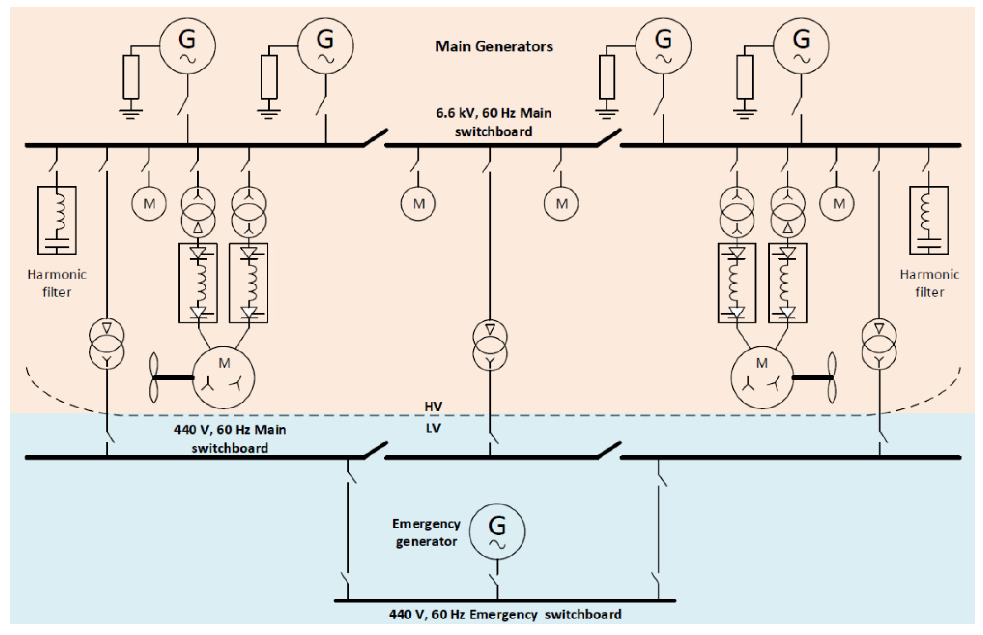
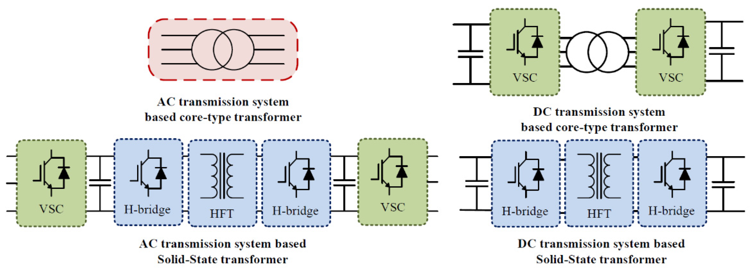
2. DC Distribution Systems Based on Conventional and Solid-State Transformers

The difference between the AC and DC transmission systems, depicted in Figure 2, should be considered in justifying the cost and efficiency of the SST [27]. In this regard, the system costs are higher in the case of the SST because they are compared with a mature technology, core-type transformers, while including the SST auxiliary circuit costs. In the AC transmission system, the SST possesses a higher cost, lower efficiency, and higher circuit footprint as it employs two converters at each side of the SST. Conversely, the core-type transformer does not require any interfacing components to perform voltage regulation and, therefore, is more advantageous in terms of system reliability, compatibility, and efficiency. However, in DC transmission systems, the traditional transformer requires three-phase converters to eventually realize the voltage regulations, which contribute to more bulky system requirements to accommodate the full power for the system, as shown in Figure 2. On the other hand, the DC distribution system based on SST requires fewer semiconductor devices, gate drivers, and heat sinks to achieve the same goal with a more compact system. Thus, in a DC distribution system, the system based on SST is more advantageous than the core-type counterpart since it offers higher efficiency and potentially reduced costs. Table 2 reveals the key differences in the DC transmission system in the case of utilizing core-type and solid-state transformers [28,29,30].
According to the extensive analysis of advanced shipboard power electronics carried out in Ref. [28], the SST technology maturity is yet to gain more momentum when compared to its core-type counterparts. Efficiencies up to 98% have been obtained and further enhancements are expected owing to the utilization of the wide-bandgap semiconductors, e.g., silicon carbide (SiC), which alleviate an improved power conversion system with smaller size and lower loss. Moreover, SiC MOSFETs are favorable since they are suitable for high frequency operation with fast switching capability and minimum switching loss [29]. Based on the conducted discussion, the solid-state transformer has proved to offer a multitude of merits and functionalities in DC grid applications in general and, particularly, traction ones. Therefore, this study proposes a smart SST using the latest SiC technology.
Moreover, it has been reported that the line frequency transformer-based system has efficiency between 88 and 92% in the traction applications, but the same system, when being replaced by an SST, can achieve an efficiency of more than 95% while being more compact [31]. From a commercial perspective, ABB introduced its first 1.2 MVA SST and reported an efficiency of 95% in 2012. This SST is advantageous because it allows more space for passengers and goods on shipboard and reaches a power density of 0.75 kVA/kg, which is significantly smaller and lighter than the line frequency transformer [32]. It has been proved that SSTs have lower weight per kVA than their line frequency transformer counterparts, where the 500 kVA line frequency transformer volume and weight are 3.43 m3 and 2590 kg, respectively, while the 500 kVA SST volume and weight are 1.1 m3 and 1270 kg, respectively [16]. SST is considered expensive at an early stage of deployment due to the overall system components, including controllers, gate drivers, filters, semiconductor devices, communications modules, and passive elements. The cost of SST is expected to experience significant reductions in the coming years due to continuous reductions in the components, packaging, and manufacturing costs [27].

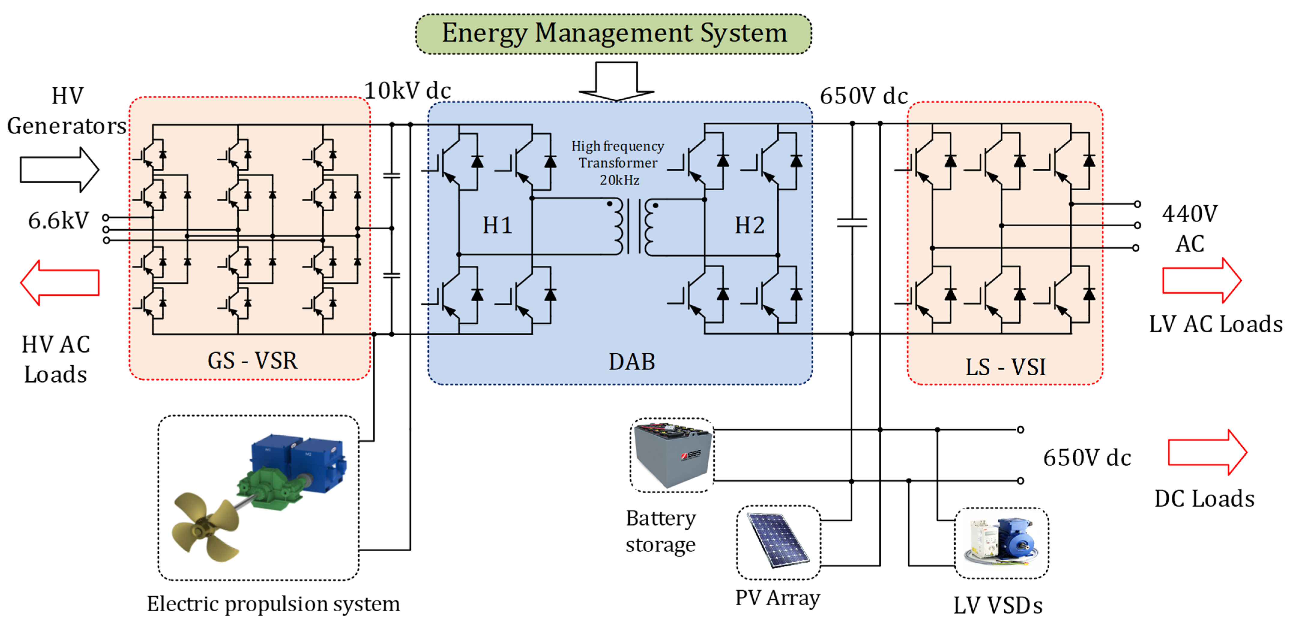
3. Overall System Control

The architecture of the proposed DC shipboard power distribution network is depicted in Figure 3. The proposed system encompasses five main components: the generator side voltage source converter (GS-VSC), the multiphase electric propulsion system, the load side voltage source inverter (LS-VSI), the dual active bridge (DAB) converter, and the PV renewable power generator with the required battery storage media. Each of these components entails a detailed investigation of the components sizing, efficient converter operation, and appropriate control technique. In this section, each system component is briefly explained.
The GS-VSR, DAB, and LS-VSI constitute the main parts of the employed SST. The SST provides a more compact size and better system controllability. It also adds new functionalities when replacing the bulky conventional electromagnetic transformers. Reducing the size and weight increases fuel-saving and reduces the required space [33]. It also facilitates the successful integration of renewables, such as fuel cells, PV modules, and energy storage systems. Moreover, the high-power electric motors used for propulsion can directly be integrated into the available high voltage DC bus as is clear from the system shown in Figure 3.
For the proposed system, the power coming from the generators is converted to DC via an AC/DC converter connected to the high voltage DC (HVDC) bus. The propulsion system can, therefore, be directly fed from this HVDC bus without disrupting the downstream loads/renewables connected to the low voltage DC (LVDC) side of the SST. Therefore, the SST resolves the impedance matching problem between the LVDC and HVDC sides on this local grid. It also allows the efficient integration of lower power sources and energy storage devices, which further reduces the encountered volume and complexity problems of the conventional systems.
High power electric converters are vital interfaces between the functional blocks and the DC distribution system. Rectifiers for generators take the tasks of HVDC bus voltage regulation and power sharing. Inverters for propulsion motors are responsible for driving the motor under different operating conditions. Bidirectional DC/DC converters for energy storage systems (ESSs) are used to provide supply–demand balance and voltage fluctuation mitigation.

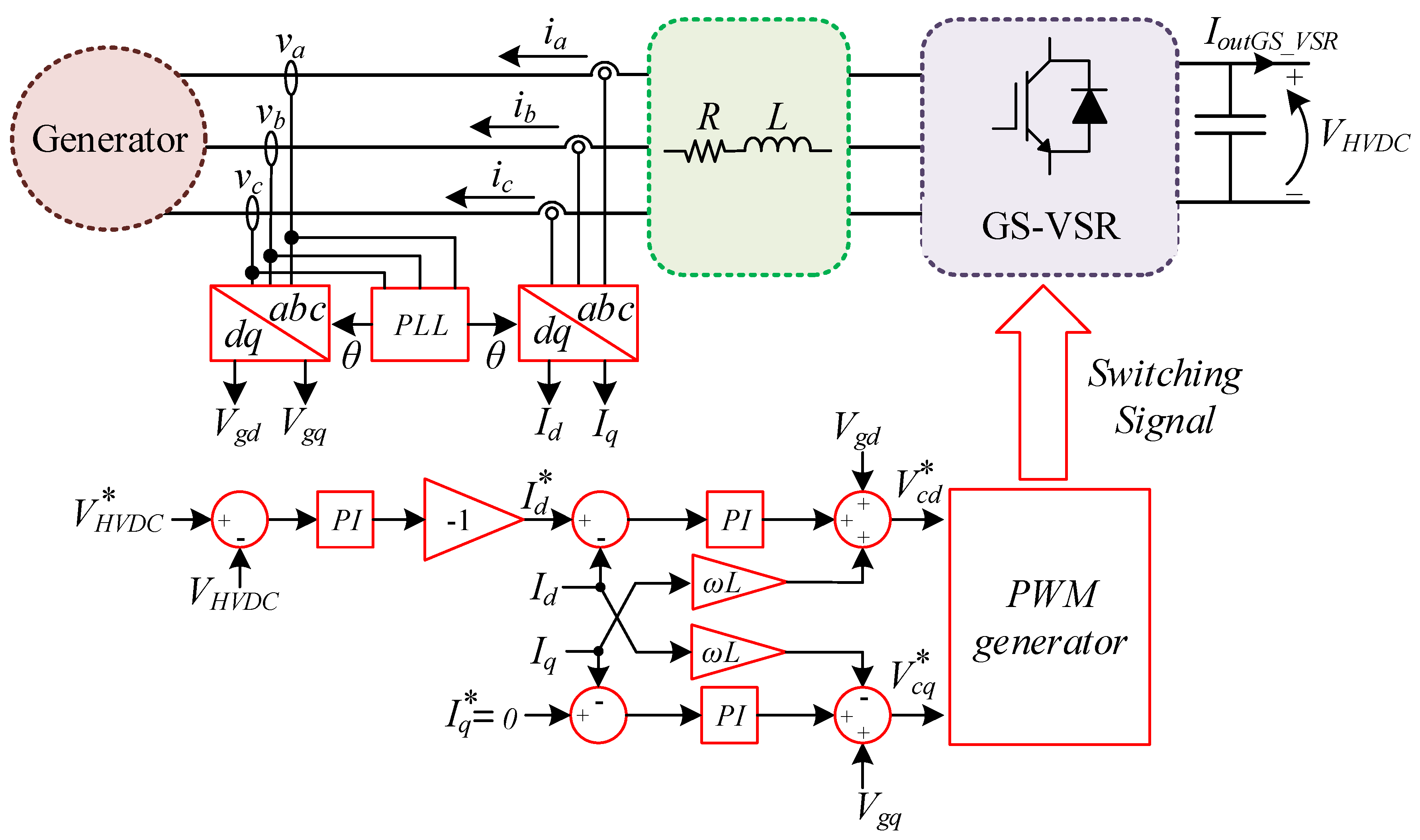
3.1. Generator Side Voltage Source Rectifier

DC shipboard power systems commonly employ high voltage levels specially at the generation side; therefore, multilevel converters are necessarily called for this application. Numerous multilevel converters have been presented for various traction and electric ships applications, such as neutral point clamped (NPC) converters [34,35,36] and modular multilevel converters (MMCs) for high voltage levels [37], cascaded H-bridge (CHB) converters [38], and flying capacitor converters [39]. In this paper, a three-level NPC converter at the generator side is utilized owing to its advantages, such as low semiconductor stresses, improved output voltage and current quality, dv/dt reduction, low losses, and high efficiency [9,40]. The three-level NPC has shown promise in practical marine propulsion drives developed by ABB [41] and Siemens [42] for synchronous machines and IMs. Moreover, the developed three-level NPC converter is based on the high-voltage and fast switching wide-bandgap SiC devices [28]. Thus, the same performance with the two-level VSC is ensured, albeit with reduced passive components. Consequently, the converter design becomes less complex, and its cost is lowered.
The proper operation of an NPC requires a stable DC-link voltage at a constant voltage level. This is accomplished with DC split-capacitors and a feedback voltage control loop. The selection of the DC-link capacitors highly depends on the voltage and power ratings and can be achieved based on analytical expression [35].
The controller block diagram of the GS-VSR is shown in Figure 4, where the voltage-oriented control (VOC) along with sinusoidal pulse width modulation (SPWM) technique are utilized in this study. The reference value for the HVDC bus voltage, V H V D C , must be chosen high enough to keep the VSR body diodes blocked. This reference value is compared with the measured HVDC bus voltage, V H V D C , and the voltage error is used to derive the reference direct current component, I d , of the line currents using a PI controller. Whereas, the reference quadrature current component, I q , is set to zero to ensure a unity power factor operation. This represents the simplest control technique for this topology. The GS-VSR voltage d q -components, V c d and V c q , are given by Equations (1) and (2), respectively:
V c d = V g d + R i d + L d i d d t + ω L i q
V c q = V g q + R i q + L d i q d t ω L i d
where V g d and V g q are the d q -components of the generator voltage. The line resistance and inductance are R and L , respectively. Moreover, i d and i q are the d q -components of the line currents. To realize unity power factor operation, the reference quadrature current component, I q , is set to zero. The PI controller, used to control the HVDC bus voltage ( V H V D C ), provides the reference value of the d-component, I d , of the line current. To independently control i d and i q , the controller is designed so that the GS-VSR reference voltage components, V c d and V c q , are given by Equations (3) and (4), respectively [43]:
V c d = V g d + ω L i q + K p I d i d + K i I d i d
V c q = V g q ω L i d + K p I q i q + K i I q i q  
where K p ,and K i , are the proportional and integral PI controller coefficients. It can be noted that the carrier-based PWM technique is used to control the LS-VSI.

3.2. Dual Active Bridge Converter

The dual active bridge converter is a DC/DC converter, which steps down the HVDC bus voltage to the LVDC bus voltage. It consists of three main parts: two voltage source active H-bridges interfaced by a high-frequency transformer (HFT) [44]. It is considered as a bidirectional isolated full-bridge DC/DC converter. It can achieve good efficiency using the minimum number of passive components. Hence, the DAB has a simple structure that does not require a resonant network. The design of the passive elements of this DC/DC converter is focused on the DC-link capacitors and the HFT. The HFT is the key building block of the DAB, which is the substitution of the traditional 50/60 Hz power transformer offering a multitude of functionalities over the conventional transformer, including significant size and volume reduction, bidirectional power flow control, and fault current limitation. The detailed design procedures of the HFT are presented in Ref. [45], where the key points in the design are the core magnetic material, the geometry of the transformer, and the structure of the core and the windings.
Several modulation techniques have been used to control the power flow in the DAB converter. Amongst them, the phase shift modulation (PSM) technique is used along with PWM control, while the soft switching technique is employed to reduce the switching losses. The PSM techniques are classified into single phase shift (SPS), dual phase shift (DPS), extended phase shift (EPS), and triple phase shift (TPS) [46]. The SPS technique is used in this study due to its fast response, high dynamics, and easier soft-switching control. In the SPS technique, the PWM signal of each H-bridge is controlled with a 50% duty cycle to generate square-wave voltages at each side of the HFT. These primary and secondary voltages are phase shifted with a time delay calculated as a ratio, D , of the half cycle of the square-wave voltage. The voltage induced on the DAB inductor due to the phase shift, D , affects the current flow in the DAB converter, which transfers power, P D A B , from the HVDC side to the LVDC side using Equation (5).
P D A B = N D   V H V D C   V L V D C   D 1 D 2 f D   L D
where N D , is the HFT turns ratio, f D , is the HFT frequency, and L D is the DAB leakage inductance. The input voltage, V H V D C , of the DAB converter is regulated by the GS-VSC, which implies that the DAB converter controls the output voltage, V L V D C , using a PI controller, as shown in Figure 5. The circulating current owing to the mismatch between the voltage amplitudes of the two transformer sides as well as the inability to reach the zero-voltage switching (ZVS) in the whole range of the power are the main drawbacks of the SPS modulation technique [47,48].
Most recent propulsion systems for large vessels are now based on electric motors with multiple three-phase winding. The multi-phase powertrain system ensures high reliability as well as reduces the current rating of the employed semi-conductors by splitting the motor power among a higher number of phases. This technology has recently emerged as a leading technology in hybrid as well as full electric ships [49]. This way, the required multiphase power converter can directly be connected to the HVDC bus of the proposed system, as shown in Figure 3.
In this paper, an asymmetrical six-phase motor is built and integrated into the system to investigate the effect of the motor dynamics on the performance of the proposed SST-based distribution system. The machine construction can simply be made by rewinding a standard three-phase motor, while two three-level three-phase inverters are used to supply this motor [50]. Accordingly, the well-known V/f control, commonly used in such large power applications, is designed based on the system full-power rating. The V/f control can provide an acceptable dynamic response via maintaining the rated flux for most of the operating region of the induction motor. The applied terminal voltage, V s , can be expressed as in Equation (6):
V s = V s , r a t e d ω e , r a t e d ω e
where V s , r a t e d , and ω e ,   r a t e d , are the rated per-phase terminal voltage and frequency, respectively.
Typically, in medium voltage high-power induction motor drives, V/f control is used to control the speed of the asymmetrical six-phase (ASP) machines, as shown in Figure 6 [51]. The speed of ASP, ω m , is fed back to the PI regulator to maintain the speed reference, ω m , of the ASP machine. Meanwhile, the slip regulator calculates the slip frequency, ω s l , based on the speed controller output. The reference synchronous speed, ω m s , is then obtained from the summation of the rotor speed, ω m , and the slip frequency, ω s l . The V/f characteristic is then used to obtain the reference voltage, V , as depicted in Figure 6.

3.3. PV Array and ESS

The proposed shipboard electric power system involves the integration of PV modules and storage batteries into the LVDC bus of the proposed DC distribution network. The PV-battery system supports the main generators by supplying part of the power to the LVDC bus loads and the HVDC bus propulsion motors in times of PV peak power, which adds to the efficient operation of the whole system. The PV system employed a maximum power point tracking (MPPT) control algorithm applied to the PV converter to deliver the maximum power from the PV panels. Meanwhile, the control algorithm of the ESS is shown in Figure 7, which is considered a power management control scheme that depends mainly on PV power generated, P P V , state of charge S o C , and the power limit specified by the possible average power that can be supplied from the PV and battery system, P L i m . In this algorithm, batteries switch between charging and discharging modes defined by the SoC and the PV power status, which determine the power supplied by the ESS to the load, P E S S . Therefore, the LVDC bus powers are kept balanced. When the limit of the batteries is reached, the power balance is ensured by the power supplied by the DAB converter, P D A B , from the HVDC bus side regardless of the case of the PV power, P P V . If the PV power, P P V , is higher than the limit power, P L i m , the storage element is to be charged depending on the S o C state of the batteries. When the batteries reach the maximum S o C state at 90%, the charging process stops and the excess PV power is transferred back to the HVDC bus side to feed the propulsion system. On the other hand, the batteries are discharging when the PV power, P P V , is less than the limit power, P L i m . In that case, the load is supplied by the batteries until its S o C reaches the minimum limit at 30%. Accordingly, the excess load is supplied from the HVDC bus side through the DAB converter, P D A B .

4. Simulation Results

In order to validate the proposed SST-based shipboard electric system, detailed simulations have been conducted for three different scenarios using MATLAB/Simulink platform. Table 3 reveals the design parameters of each component of the shipboard electric system. The following subsections present the three simulation scenarios.

4.1. Full Load Operation of the Shipboard Electric Power System

Scenario 1 involves simulating the whole shipboard system at the rated conditions of each component and delivering the full load power from the generator, P G , 2 MW, to the propulsion motor, P M o t o r , 1.5 MW, and the LVDC side loads, P L o a d , 0.5 MW. The control techniques discussed previously for each stage converter are applied, where the GS-VSR regulates the HVDC bus voltage, V H V D C , at 10 kV and ensures the unity power factor operation of the generators ( Q g   = 0). Besides, the DAB converter keeps the LVDC bus voltage, V L V D C , regulated at 650 V and provides bidirectional power flow operation. The propulsion motor drive system controls the motor speed to be constant at the rated speed, N , of 1500 rpm. The PV and the storage system are operated to feed part of the LVDC side loads, P B B , 0.1 MW, and the DAB converter supplies the rest of the power, P D A B , 0.4 MW.
The generator plots are shown in Figure 8, namely the generator currents, voltage, active, and reactive powers. It is clear that the GS-VSR successfully controls the generator current at the unity power factor with an acceptable high quality current waveform, as shown in Figure 8a. This conclusion is further proved as the generator’s active power, P G , supplies the whole system, while the reactive power, Q G , is nullified, as depicted in Figure 8b. Moreover, the HVDC side operation is presented in Figure 9, highlighting the HVDC bus voltage and powers. It is shown that the well-designed control technique at the GS-VSR can regulate the HVDC bus voltage, V H V D C , at 10 kV.
In addition, the GS-VSR can supply the DAB and six-phase motor with around 2 MW, which is divided among the motor demand and the LVDC side demand that is delivered by the DAB converter.
Similarly, the LVDC operation, namely LVDC voltage and powers, is highlighted in Figure 10. Accordingly, the DAB converter can efficiently regulate the LVDC bus voltage, V L V D C , at 650 V regardless of its loading condition. Meanwhile, the LVDC side powers, i.e., VSI input power, P V S I , DAB output power, P D A B , PV power, P P V , and the ESS power, P E S S , are filtered and contain lower harmonic content. For instance, The LS-VSI consumes around 0.5 MW, which is supplied by the DAB and the PV-battery system with 0.4 MW and 0.1 MW power shares, respectively.
For the six-phase motor, the simulation results are shown in Figure 11. The employed machine is an asymmetrical six-phase with a spatial phase shift of 30 ° between the two three-phase winding sets. The motor speed is regulated to follow the reference speed, which is set to 1500 rpm. For prolusion motor applications, the load torque is proportional to the speed square. Hence, the motor developed torque rises as the motor speed increases.

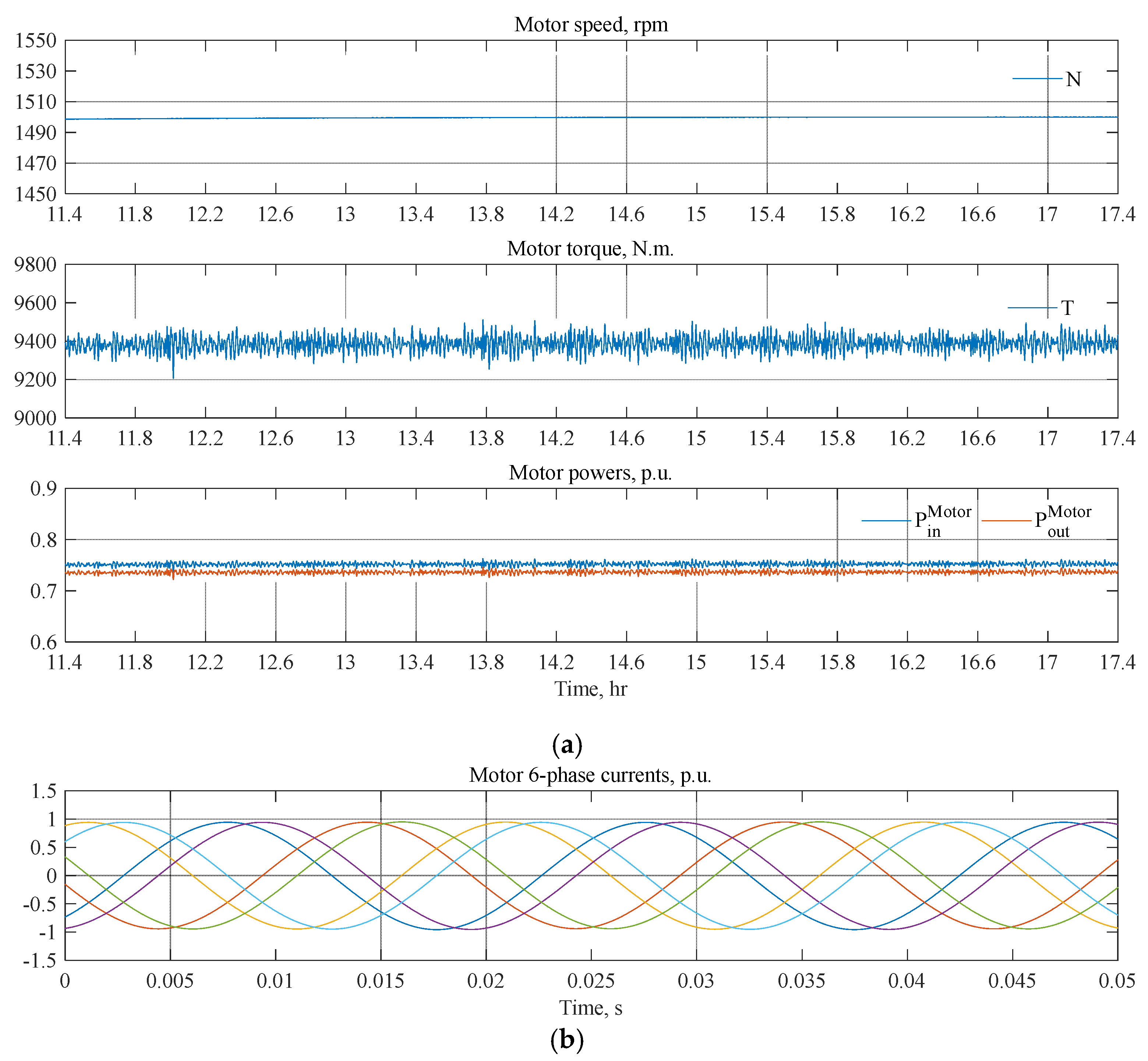
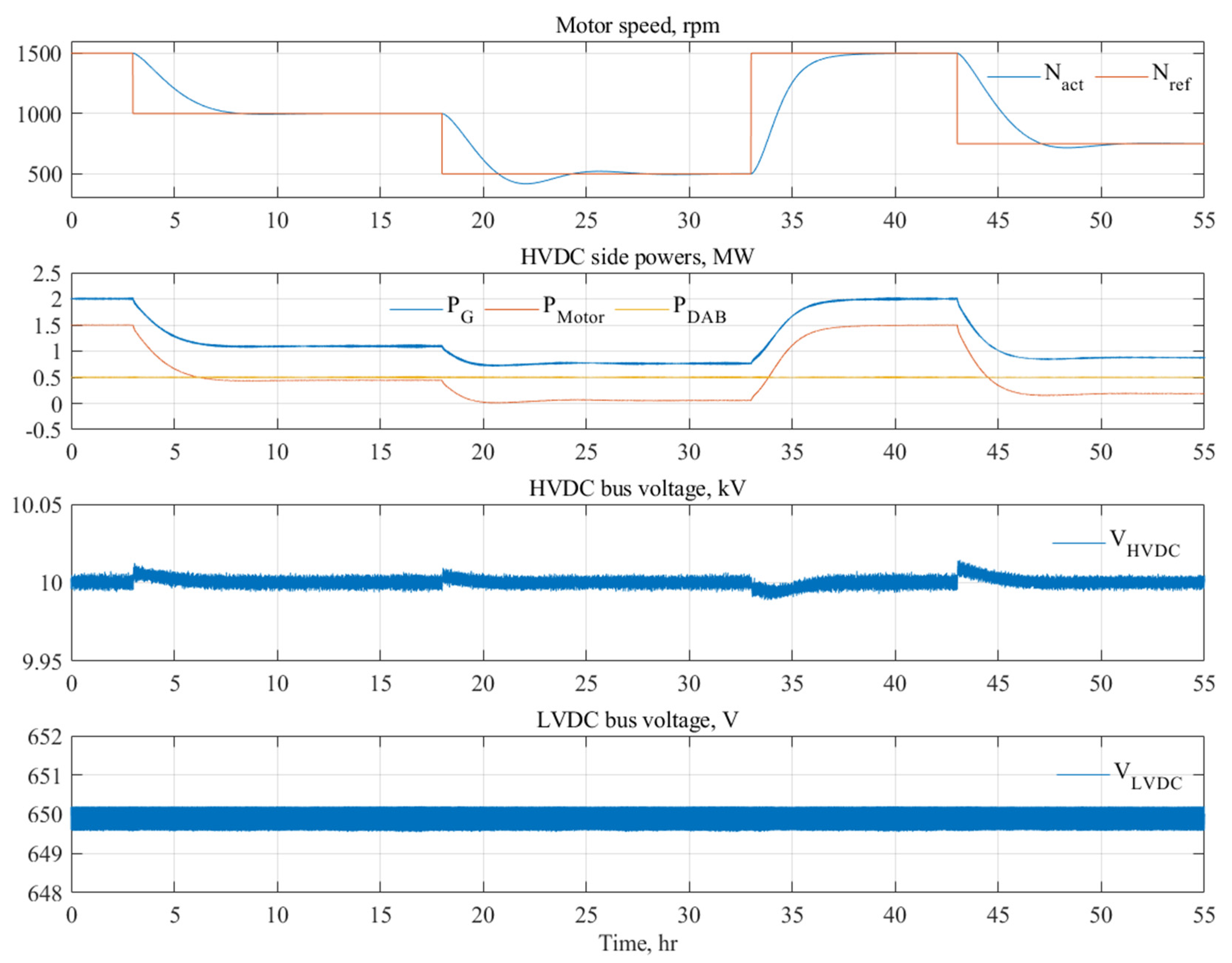
4.2. Effect of the Propulsion System Dynamics on the SST

Scenario 2 simulates the dynamics occurring in the propulsion system due to the speed variation in the propulsion motors and its effect on each part of the SST, the DC-link voltages at different parts of the system, and the generator operation. The PV-battery system is disconnected in this scenario and the LVDC bus is connected to the LVDC side loads, which draw the full load power of 0.5 MW from the DAB converter. The effect of the propulsion motor dynamics on the primary and secondary voltage levels of the SST is illustrated in Figure 12. The 6-phase motor input speed is varied over time and, hence, the motor developed torque will also be varying. It is shown that the actual speed, N a c t , follows its reference speed, N r e f , albeit with a delayed response owing to the high inertia of the motor. Accordingly, the powers at the HVDC side are controlled, in which the DAB power, P D A B , is around 0.5 MW, the power delivered to the propulsion drive system, P M o t o r , varies depending on the speed value, and then the GS_VSC power, P G , is the sum of the DAB power, P D A B , and the motor drive power, P M o t o r .
The GS-VSR controller succeeds to restore the HVDC bus voltage, V H V D C , to the reference value, 10 kV. The main objective of the DAB converter is to regulate the LVDC bus voltage, V L V D C , at 650 V. It is clear that the LVDC bus voltage, V L V D C , is well regulated at the reference voltage despite the motor drive dynamics, with low voltage ripple.

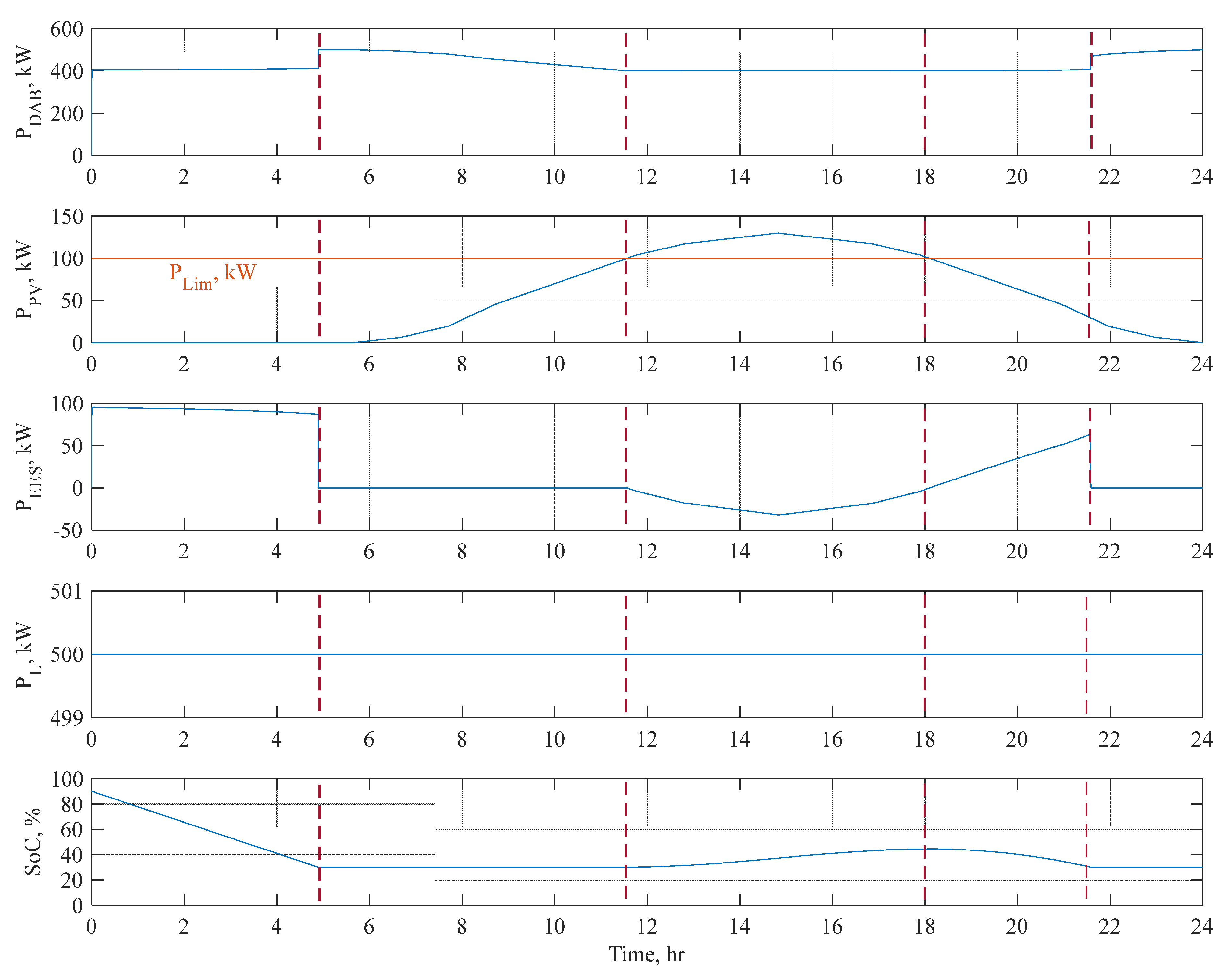
4.3. PV-Battery Power Management Algorithm
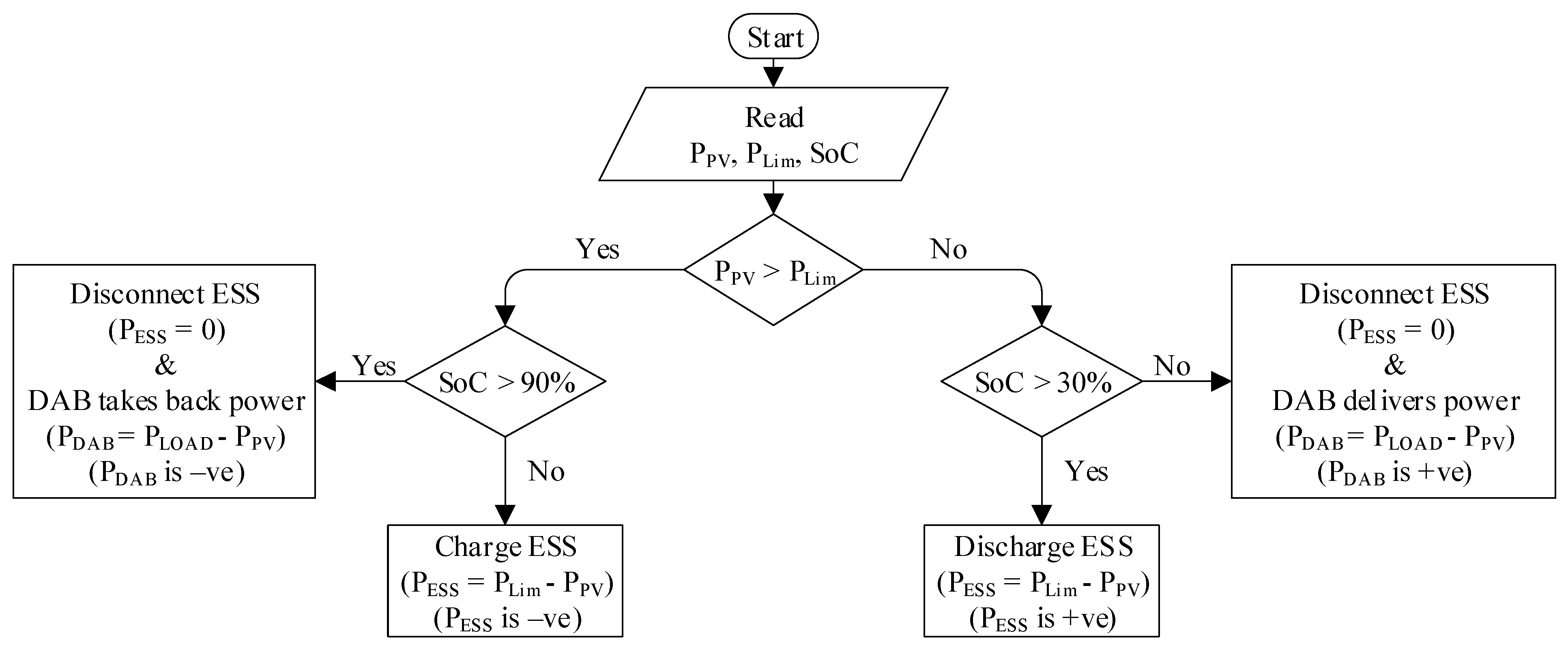
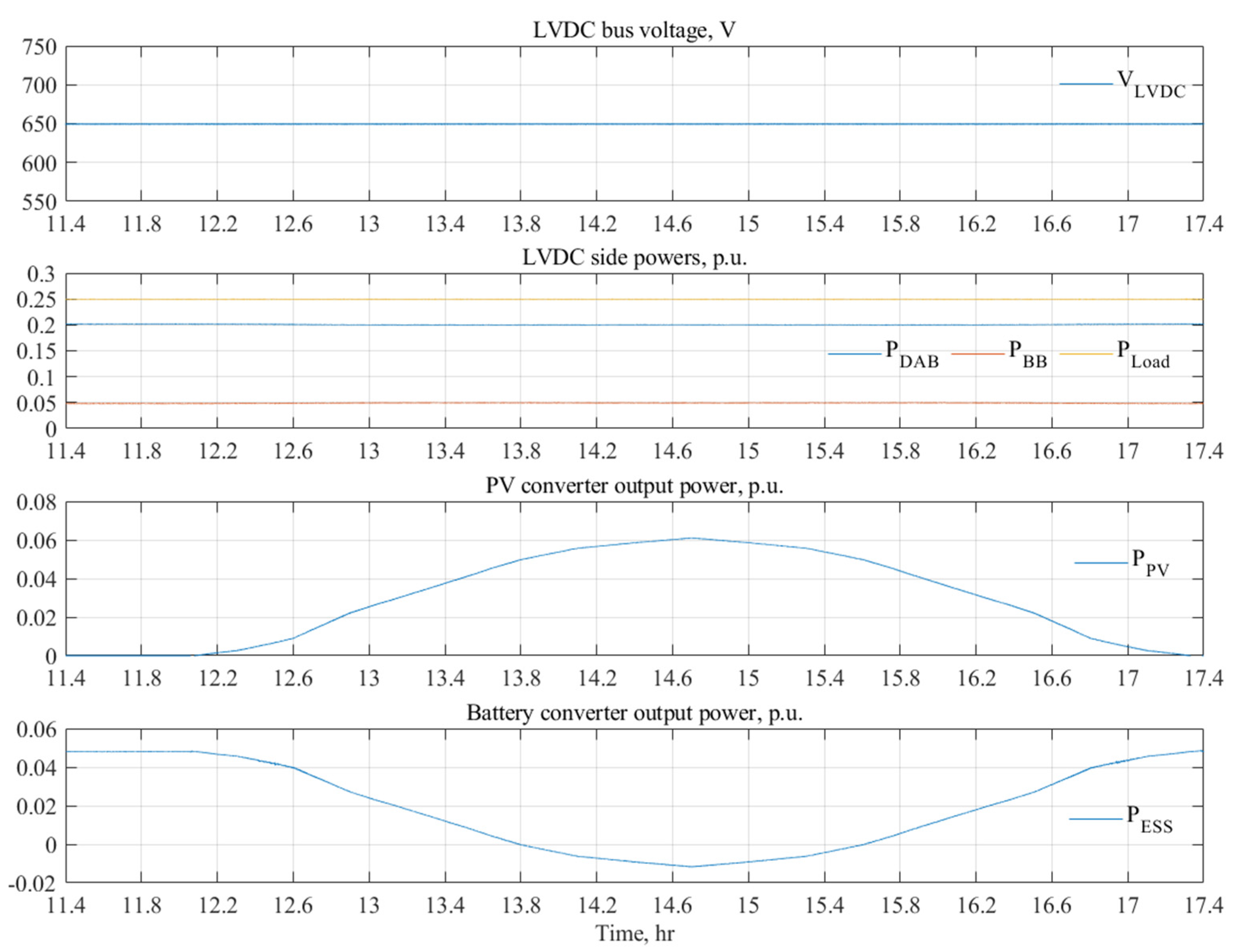
In scenario 3, the simulation results of the power management algorithm, which is utilized to control the PV-battery system during different irradiance and SoC conditions, are given in this subsection. Besides, the corresponding effect on the power delivered from the DAB converter to the LVDC side, P D A B , and LVDC side loads, P L o a d , is considered. The system is simulated over a 24-h domain. The LVDC side loads are assumed to consume the full power of 500 kW.
In addition to the efficient shipboard DC network control, a power management strategy is developed to optimally dispatch the power at the LVDC side on a daily basis, as depicted in Figure 13. It is assumed that the load demand, P L o a d , at the LVDC bus side is constant during the day, with a value of 500 kW. Initially, the S o C of the batteries is assumed to be 90%. Besides, the limited power from the PV-battery system, P L i m , is defined to be 100 kW. The simulation scenario can be divided as follows:
(1)
Stage 1 (0–5 h): In this stage, the generated power from the PV system, P P V , is zero. Due to the limited PV-battery power and the initial S o C , the battery system power, P E S S , supports the load demand with 100 kW, which yields considerable reduction in the battery S o C , reaching 30% at 5 h. Meanwhile, the rest of the demand is supplied from the DAB power, P D A B , with 400 kW.
(2)
Stage 2 (5–11.5 h): At 5 h, the controller disconnects the battery system since the SoC drops to the minimum level. Thus, the load demand is initially supplied from the DAB converter ( P D A B = 500   k W ) only. Then, the PV system starts to share the load power, P L o a d , with the DAB converter till the end of this interval. As a result, the DAB power, P D A B , share drops to 400 kW.
(3)
Stage 3 (11.5–18 h): At the beginning of this interval, the PV power, P P V , becomes higher than the PV-battery power limit, P L i m . Thus, the battery charging process is resumed and the power difference between the PV power, P P V , and the limit power, P L i m , is fed back to the ESS. This, therefore, justifies the negative value of the ESS power, P E S S . During this period, the DAB supplies 400 kW to the load, whereas the PV-battery system shares the remaining load demand. In addition, the battery S o C rises to 45% at the end of the period.
(4)
Stage 4 (18–21.5 h): At 18 h, the battery SoC becomes higher than 30%, and the PV power, P P V , drops below the limit power, P L i m . Thus, the battery is discharging to maintain the average power supplied by the PV-battery system, P B B , 100 kW. Moreover, the DAB delivers the remaining power of 400 kW to meet the load demand.
(5)
Stage 5 (21.5–24 h): The battery is disconnected since its S o C decreases below 30%, and the DAB shares power with the PV to supply the load demand. In that case, the DAB power increases from 470 kW at 21.5 h and ends with 500 kW at 24 h.

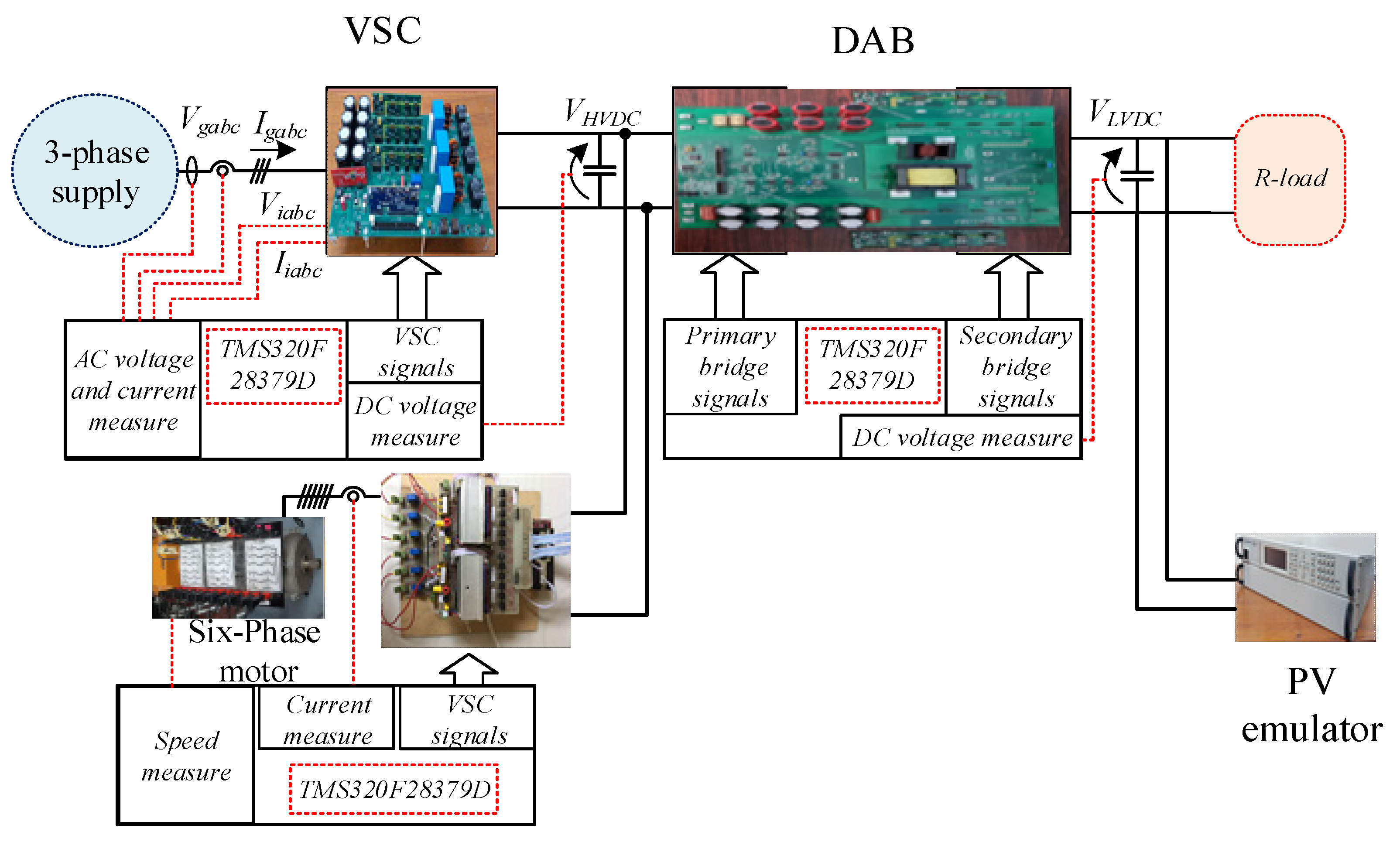
5. Experimental Investigation

This section presents the experimental evaluation of the proposed SST-based shipboard electric power system using a low-scale prototype system rated at 2 kW and a 500 V/250 V DC/DC voltage ratio. The SST, which includes the GS-VSR, DAB, and LS-VSI, is connected to an A6P propulsion motor, and a PV emulator is integrated to the SST LV side. Experiments have been conducted to show the effect of motor dynamics as well as the step loading at the LVDC side on the system performance. The experimental test-bench is depicted in Figure 14, and its parameters are given in Table 4.
The voltage source converter utilized in this hardware is an NPC-VSC. It offers bidirectional power transfer. In addition, the NPC-VSC is tied to the DAB HVDC bus. The SST uses SiC switches (SiC IGBT LSIC1MO120E0080) and utilizes 3 fans with 14000 RPM speed to cool up the heat sinks and the HFT. A 50 Hz three-phase supply is used to emulate the generator. The asymmetrical six-phase propulsion motor can be connected to the same HVDC bus without affecting the SST-based LVDC distribution system.
The 6-phase motor drive system, namely the motor and inverter, is built by rewinding a standard three-phase induction motor with two three-phase winding sets, where the spatial phase shift between the two three-phase winding sets is 30 ° . The motor is mechanically loaded using a coupled DC-generator having the same power rating. The DSP controller board employed in this drive is the TMS320F28379D Launchpad. Finally, the PV system operates using MPPT algorithm applied on boost converter, which have been tested using a Keysight E4360A modular solar array simulator.
The generator line currents are shown in Figure 15, where balanced currents are obtained. Moreover, the generator phase voltage and current are in-phase, which ensures unity power factor operation at the generator AC side. Moreover, the GS-VSR can successfully maintain the input DC voltage of the DAB during the full load operation, as shown in Figure 16. Meanwhile, the output DC voltage of the DAB is well regulated at the desired reference throughout the system operation, which, therefore, proves that the DAB is properly functioning. It is worth mentioning that the DAB is controlled based on SPS modulation technique with a feedback PI control. The effect of full-load step-loading at the secondary side is shown at 10 s.
Figure 17 shows the six-phase motor dynamic performance. In the asymmetrical configuration, the spatial phase shift between the two three-phase winding groups is 30 0 , which is proved in Figure 17. Moreover, the V/f control of A6P machine can efficiently respond to the speed change from 500 to 1000 rpm at 1.5 s. Needless to say, the motor torque will proportionally increase with this speed change.
Finally, the PV emulator characteristic and the corresponding experimental waveforms are shown in Figure 18 and Figure 19, respectively. The solar array monitor shown in Figure 18 shows the characteristics of the PV emulator and the corresponding operating point. The MPPT technique can successfully track the maximum power point, as shown in Figure 18. Based on the ratings listed in Table 4, the PV emulator voltage and current output are depicted in Figure 19.

6. Conclusions

This paper presented a design case study of a DC power distribution network that can be used for shipboard applications. The main contributions can be summarized as follows:
  • An efficient SST is proposed based on SiC switches; therefore, the system efficiency can be considerably increased. Moreover, the DC voltages at the DAB sides were well-regulated under steady-state and dynamic conditions.
  • The effect of propulsion motor dynamics on the proposed system components has been presented, a key contribution of this study. It is clear that the DC voltages are regulated during the whole process of the proposed system.
  • A power management strategy was efficiently employed to control demand at the LVDC side by optimally dispatching the load among the main generation unit, PV array, and ESS.
To further verify the proposed SST-based DC power system, experimental results using a 2-kW laboratory test rig were performed, where the power demand was met without violating the shipboard applicable regulations.

Author Contributions

Formal analysis, A.I. and M.Y.M.; funding acquisition, S.A. and E.H.; investigation, A.I. and M.S.A.-M.; methodology, M.S.A.-M.; project administration, A.S.A.-K. and N.A.E.; resources, A.S.A.-K., M.S.H., E.H. and N.A.E.; software, M.Y.M.; supervision, M.S.H.; writing—original draft, A.I., M.S.A.-M. and M.Y.M.; writing—review & editing, A.S.A.-K., M.S.H., S.A. and N.A.E. All authors have read and agreed to the published version of the manuscript.

Funding

This paper is based upon work supported by Science. Technology & Innovation Funding Authority (STDF) under grant (37066).

Institutional Review Board Statement

Not applicable.

Informed Consent Statement

Not applicable.

Data Availability Statement

Data are contained within the article.

Conflicts of Interest

The authors declare no conflict of interest.

References

  1. Hansen, J.F.; Wendt, F. History and state of the art in commercial electric ship propulsion, integrated power systems, and future trends. Proc. IEEE 2015, 103, 2229–2242. [Google Scholar] [CrossRef]
  2. Javaid, U.; Freijedo, F.D.; Dujic, D.; van der Merwe, W. MVDC supply technologies for marine electrical distribution systems. CPSS Trans. Power Electron. Appl. 2018, 3, 65–76. [Google Scholar] [CrossRef]
  3. Jin, Z.; Meng, L.; Guerrero, J.M.; Han, R. Hierarchical control design for a shipboard power system with DC distribution and energy storage aboard future more-electric ships. IEEE Trans. Ind. Inform. 2018, 14, 703–714. [Google Scholar] [CrossRef] [Green Version]
  4. Kim, S.; Kim, S.-N.; Dujic, D. Extending protection selectivity in DC shipboard power systems by means of additional bus capacitance. IEEE Trans. Ind. Electron. 2020, 67, 3673–3683. [Google Scholar] [CrossRef]
  5. Ulissi, G.; Kim, S.; Dujic, D. Solid-State Technology for Shipboard DC Power Distribution Networks. IEEE Trans. Ind. Electron. 2021, 68, 12100–12108. [Google Scholar] [CrossRef]
  6. Sulligoi, G.; Bosich, D.; Vicenzutti, A.; Khersonsky, Y. Design of zonal electrical distribution systems for ships and oil platforms: Control systems and protections. IEEE Trans. Ind. Appl. 2020, 56, 5656–5669. [Google Scholar] [CrossRef]
  7. Shagar, V.; Jayasinghe, S.G.; Enshaei, H. Effect of load changes on hybrid shipboard power systems and energy storage as a potential solution: A review. Inventions 2017, 2, 21. [Google Scholar] [CrossRef] [Green Version]
  8. Ulissi, G.; Lee, S.-Y.; Dujic, D. Solid-state bus-tie switch for shipboard power distribution networks. IEEE Trans. Transp. Electrif. 2020, 6, 1253–1264. [Google Scholar] [CrossRef]
  9. Xu, L.; Guerrero, J.M.; Lashab, A.; Wei, B.; Bazmohammadi, N.; Vasquez, J.; Abusorrah, A.M. A Review of DC Shipboard Microgrids Part I: Power Architectures, Energy Storage and Power Converters. IEEE Trans. Power Electron. 2021, 37, 5155–5172. [Google Scholar] [CrossRef]
  10. Kumar, D.; Zare, F.; Ghosh, A. DC microgrid technology: System architectures, AC grid interfaces, grounding schemes, power quality, communication networks, applications, and standardizations aspects. IEEE Access 2017, 5, 12230–12256. [Google Scholar] [CrossRef]
  11. Beheshtaein, S.; Cuzner, R.M.; Forouzesh, M.; Savaghebi, M.; Guerrero, J.M. DC microgrid protection: A comprehensive review. IEEE J. Emerg. Sel. Top. Power Electron. 2019. [Google Scholar] [CrossRef]
  12. Khersonsky, Y.; Ericsen, T.; Bishop, P.; Amy, J.; Andrus, M.; Baldwin, T.; Bartolucci, B.; Benavides, N.; Boroyevich, D.; Chaudhary, A.; et al. Recommended Practice for 1 to 35 kV Medium Voltage DC Power Systems on Ships; IEEE: New York, NY, USA, 2010. [Google Scholar]
  13. Amy, J.V. Considerations in the design of naval electric power systems. In Proceedings of the IEEE Power Engineering Society Summer Meeting, Chicago, IL, USA, 21–25 July 2002; Volume 1, pp. 331–335. [Google Scholar]
  14. Javaid, U.; Dujić, D.; van der Merwe, W. MVDC marine electrical distribution: Are we ready? In Proceedings of the IECON 2015—41st Annual Conference of the IEEE Industrial Electronics Society, Yokohama, Japan, 9–12 November 2015; pp. 000823–000828. [Google Scholar]
  15. Huber, J.E.; Kolar, J.W. Volume/weight/cost comparison of a 1MVA 10 kV/400 V solid-state against a conventional low-frequency distribution transformer. In Proceedings of the 2014 IEEE Energy Conversion Congress and Exposition (ECCE), Pittsburgh, PA, USA, 14–18 September 2014; pp. 4545–4552. [Google Scholar]
  16. Mishra, D.K.; Ghadi, M.J.; Li, L.; Hossain, J.; Zhang, J.; Ray, P.K.; Mohanty, A. A review on solid-state transformer: A breakthrough technology for future smart distribution grids. Int. J. Electr. Power Energy Syst. 2021, 133, 107255. [Google Scholar] [CrossRef]
  17. Georgilakis, S. Spotlight on Modern Transformer Design; Springer Science & Business Media: Berlin/Heidelberg, Germany, 2009. [Google Scholar]
  18. She, X.; Huang, A.Q.; Wang, F.; Burgos, R. Wind energy system with integrated functions of active power transfer, reactive power compensation, and voltage conversion. IEEE Trans. Ind. Electron. 2012, 60, 4512–4524. [Google Scholar] [CrossRef]
  19. Brando, G.; Dannier, A.; del Pizzo, A.; Rizzo, R. A high performance control technique of power electronic transformers in medium voltage grid-connected PV plants. In Proceedings of the XIX International Conference on Electrical Machines-ICEM, Rome, Italy, 6–8 September 2010; Volume 2010, pp. 1–6. [Google Scholar]
  20. Lin, N.; Liu, P.; Dinavahi, V. Component-level thermo-electromagnetic nonlinear transient finite element modeling of solid-state transformer for DC grid studies. IEEE Trans. Ind. Electron. 2020, 68, 938–948. [Google Scholar] [CrossRef]
  21. Huang, L.; Li, Y.; Cui, Q.; Xie, N.; Zeng, J.; Shu, J. Research on optimal configuration of AC/DC hybrid system integrated with multiport solid-state transforms and renewable energy based on a coordinate strategy. Int. J. Electr. Power Energy Syst. 2020, 119, 105880. [Google Scholar] [CrossRef]
  22. Fotoohabadi, H.; Mohammadi, M. Evaluating the technical benefits of AC–DC hybrid distribution systems consisting of solid-state transformers using a multiobjective index. Sustain. Energy Grids Netw. 2019, 18, 100224. [Google Scholar] [CrossRef]
  23. Zhao, T.; Zhang, X.; Wang, M.; Mao, W.; Li, F.; Wang, F.; Wang, X. Module Power Balance Control and Redundancy Design Analysis of Cascaded PV Solid-State Transformer Under Fault Conditions. IEEE J. Emerg. Sel. Top. Power Electron. 2020, 9, 677–688. [Google Scholar] [CrossRef]
  24. Ulissi, G.; Lee, S.-Y.; Dujic, D. Scalable solid-state bus-tie switch for flexible shipboard power systems. IEEE Trans. Power Electron. 2021, 36, 239–247. [Google Scholar] [CrossRef]
  25. Kirtley, J.L.; Banerjee, A.; Englebretson, S. Motors for ship propulsion. Proc. IEEE 2015, 103, 2320–2332. [Google Scholar] [CrossRef]
  26. Nanoty, A.S.; Chudasama, A. Design of multiphase induction motor for electric ship propulsion. In Proceedings of the 2011 IEEE Electric Ship Technologies Symposium, Alexandria, VA, USA, 10–13 April 2011; pp. 283–287. [Google Scholar]
  27. Saleh, S.A.; Ozkop, E.; Alsayid, B.; Richard, C.; Onge, X.F.S.; McDonald, K.M.; Chang, L. Solid-State Transformers for Distribution Systems–Part II: Deployment Challenges. IEEE Trans. Ind. Appl. 2019, 55, 5708–5716. [Google Scholar] [CrossRef]
  28. Wang, F.; Zhang, Z.; Ericsen, T.; Raju, R.; Burgos, R.; Boroyevich, D. Advances in power conversion and drives for shipboard systems. Proc. IEEE 2015, 103, 2285–2311. [Google Scholar] [CrossRef]
  29. Huber, J.E.; Kolar, J.W. Applicability of solid-state transformers in today’s and future distribution grids. IEEE Trans. Smart Grid 2017, 10, 317–326. [Google Scholar] [CrossRef]
  30. Orosz, T. Evolution and modern approaches of the power transformer cost optimization methods. Period. Polytech. Electr. Eng. Comput. Sci. 2019, 63, 37–50. [Google Scholar] [CrossRef] [Green Version]
  31. Dujic, D.; Zhao, C.; Mester, A.; Steinke, J.K.; Weiss, M.; Lewdeni-Schmid, S.; Chaudhuri, T.; Stefanutti, P. Power Electronic Traction Transformer-Low Voltage Prototype. IEEE Trans. Power Electron. 2013, 28, 5522–5534. [Google Scholar] [CrossRef]
  32. Claessens, M.; Dujic, D.; Canales, F.; Steinke, J.K.; Stefanutti, P.; Vetterli, C. Traction transformation. ABB Rev. 2012, 1, 11–17. [Google Scholar]
  33. Khan, M.T.A.; Milani, A.A.; Chakrabortty, A.; Husain, I. Dynamic modeling and feasibility analysis of a solid-state transformer-based power distribution system. IEEE Trans. Ind. Appl. 2017, 54, 551–562. [Google Scholar] [CrossRef]
  34. Bhattacharya, S.; Mascarella, D.; Joós, G.; Cyr, J.-M.; Xu, J. A dual three-level T-NPC inverter for high-power traction applications. IEEE J. Emerg. Sel. Top. Power Electron. 2016, 4, 668–678. [Google Scholar] [CrossRef]
  35. Choudhury, A.; Pillay, P. Space Vector Based Capacitor Voltage Balancing for a Three-Level NPC Traction Inverter Drive. IEEE J. Emerg. Sel. Top. Power Electron. 2019, 8, 1276–1286. [Google Scholar] [CrossRef]
  36. Youssef, M.Z.; Woronowicz, K.; Aditya, K.; Azeez, N.A.; Williamson, S.S. Design and development of an efficient multilevel DC/AC traction inverter for railway transportation electrification. IEEE Trans. Power Electron. 2015, 31, 3036–3042. [Google Scholar] [CrossRef]
  37. Ronanki, D.; Williamson, S.S. A simplified space vector pulse width modulation implementation in modular multilevel converters for electric ship propulsion systems. IEEE Trans. Transp. Electrif. 2018, 5, 335–342. [Google Scholar] [CrossRef]
  38. Debnath, S.; Qin, J.; Bahrani, B.; Saeedifard, M.; Barbos, P. Operation, control, and applications of the modular multilevel converter: A review. IEEE Trans. Power Electron. 2015, 30, 37–53. [Google Scholar] [CrossRef]
  39. Pallo, N.; Foulkes, T.; Modeer, T.; Coday, S.; Pilawa-Podgurski, R. Power-dense multilevel inverter module using interleaved GaN-based phases for electric aircraft propulsion. In Proceedings of the 2018 IEEE Applied Power Electronics Conference and Exposition (APEC), San Antonio, TX, USA, 4–8 March 2018; pp. 1656–1661. [Google Scholar]
  40. Poorfakhraei, A.; Narimani, M.; Emadi, A. A review of modulation and control techniques for multilevel inverters in traction applications. IEEE Access 2021, 9, 24187–24204. [Google Scholar] [CrossRef]
  41. ABB. ABB Medium Voltage Drives Product Overview. 2016. Available online: https://library.e.abb.com/public/4e960207fbc5045885257b63006788c9/MVD-PHPF01U-EN-REVE.pdf (accessed on 20 December 2021).
  42. SIEMENS. The Reliable Medium-Voltage Drive with IGCTs. Available online: https://www.lda-portal.siemens.com/staticmedia/109764436-ws-sinamics-sm150-gm150-igct-en.pdf (accessed on 20 December 2021).
  43. Xu, L.; Yao, L.; Sasse, C. Grid Integration of Large DFIG-Based Wind Farms Using VSC Transmission. IEEE Trans. Power Syst. 2007, 22, 976–984. [Google Scholar] [CrossRef]
  44. Ismail, A.; Hamad, M.; el Zawawi, A.; Abdallah, E.N. Local AC network support via HVDC tapping. In Proceedings of the 2017 Nineteenth International Middle East Power Systems Conference (MEPCON), Cairo, Egypt, 19–21 December 2017; pp. 1088–1092. [Google Scholar]
  45. Kumar, S. Design of high frequency power transformer for switched mode power supplies. In Proceedings of the 2016 International Conference on Emerging Trends in Engineering, Technology and Science (ICETETS), Pudukkottai, India, 24–26 February 2016; pp. 1–5. [Google Scholar]
  46. Zhao, B.; Song, Q.; Liu, W.; Sun, Y. Overview of Dual-Active-Bridge Isolated Bidirectional DC-DC Converter for High-Frequency-Link Power-Conversion System. IEEE Trans. Power Electron. 2014, 29, 4091–4106. [Google Scholar] [CrossRef]
  47. Mi, C.; Bai, H.; Wang, C.; Gargies, S. Operation, Design and Control of Dual H-bridge-Based Isolated Bidirectional DC-DC Converter. IET Power Electron. 2008, 1, 507–517. [Google Scholar] [CrossRef] [Green Version]
  48. Inoue, S.; Akagi, H. A Bidirectional Isolated DC—DC Converter as A Core Circuit of the Next-Generation Medium-Voltage Power Conversion System. IEEE Trans. Power Electron. 2007, 22, 535–542. [Google Scholar] [CrossRef]
  49. Levi, E.; Bojoi, R.; Profumo, F.; Toliyat, H.; Williamson, S. Multiphase induction motor drives-a technology status review. IET Electr. Power Appl. 2007, 1, 489–516. [Google Scholar] [CrossRef] [Green Version]
  50. Gritter, D.; Kalsi, S.S.; Henderson, N. Variable speed electric drive options for electric ships. In Proceedings of the IEEE Electric Ship Technologies Symposium, Philadelphia, PA, USA, 27 July 2005; pp. 347–354. [Google Scholar]
  51. Abdel-Khalik, A.S.; Hamdy, R.A.; Massoud, A.M.; Ahmed, S. Postfault control of scalar (V/f) controlled asymmetrical six-phase induction machines. IEEE Access 2018, 6, 59211–59220. [Google Scholar] [CrossRef]
Figure 1. Conventional shipboard power system [7].
Applsci 12 02001 g001
Figure 2. Transmission systems based on core-type and solid-state transformer.
Applsci 12 02001 g002
Figure 3. Proposed architecture of DC shipboard power distribution network.
Applsci 12 02001 g003
Figure 4. GS-VSR typical controller block diagram.
Applsci 12 02001 g004
Figure 5. Multiphase electric propulsion system.
Applsci 12 02001 g005
Figure 6. V/f control of asymmetrical six-phase machine.
Applsci 12 02001 g006
Figure 7. Power management control algorithm.
Applsci 12 02001 g007
Figure 8. Simulation results of the main generator. It is clear that the GS-VSR successfully controls the generator current at the unity power factor with an acceptable high quality current waveform, as shown in (a). This conclusion is further proved as the generator’s active power, P G , supplies the whole system, while the reactive power, Q G , is nullified, as depicted in (b).
Applsci 12 02001 g008
Figure 9. HVDC side operation waveforms.
Applsci 12 02001 g009
Figure 10. LVDC side operation waveforms.
Applsci 12 02001 g010
Figure 11. Six-phase motor operation waveforms. (a) presents the motor speed, torque, and powers. The employed machine is an asymmetrical six-phase with a spatial phase shift of 30° between the two three-phase winding sets, as shown in (b).
Applsci 12 02001 g011
Figure 12. Transient effect of the propulsion motor speed change on the SST dynamics.
Applsci 12 02001 g012
Figure 13. Power management simulation results.
Applsci 12 02001 g013
Figure 14. Experimental test-bench.
Applsci 12 02001 g014
Figure 15. GS-VSR voltage and current waveforms.
Applsci 12 02001 g015
Figure 16. DAB experimental readings.
Applsci 12 02001 g016
Figure 17. Asymmetrical 6-phase motor dynamic response.
Applsci 12 02001 g017
Figure 18. PV array characteristics with MPPT.
Applsci 12 02001 g018
Figure 19. PV array experimental waveforms.
Applsci 12 02001 g019
Table 1. Shipboard power distribution systems.
Conventional SystemProposed System
TransformerHigh rating power transformerLess rating power transformer
DistributionACDC
GenerationDiesel generatorsHybrid
Main functionsVoltage transformation, isolation, and power transmissionVoltage transformation, isolation, and power transmission
Additional functionsNoneAutomatic voltage regulation, power factor correction, power flow control, fault current limitation
Table 2. Comparison between the DC distribution systems based on conventional and solid-state transformers.
Core-Type TransformerSolid-State Transformer
Converter ratingFull power ratingCascaded and multilevel topologies at lower ratings
Semiconductor devices count12
(in case of utilizing three-phase PWM back to back converters)
8
(in case of utilizing full power rated H-bridges and higher for MMC topologies)
Overall system efficiency range88–92%>95%
Transformer power density0.2–0.35 kVA/kg0.5–0.75 kVA/kg
Table 3. Overall system parameters.
CategoryParameterValueCategoryParameterValue
GS-VSRRated power2 MVAPropulsion drive systemRated power1.5 MW
Line voltage6.6 kV (rms)Rated voltage6.6 kV
Frequency60 HzRated frequency50 Hz
Interface inductor4.44 mHα–β componentsRs = 0.654 Ω
Switching frequency20 kHzRr = 0.521 Ω
HVDC link voltage10 kVLls = 13.8 mH
HVDC link capacitor5593 µHLlr = 12.7 mH
DABRated power500 kVALm = 656 mH
Voltage ratio (prim/sec)10,000 V/ 650 Vx–y componentsRxy = 0.8576 Ω
Current ratio (prim/sec)50 A/769 ALxy = 3 mH
Switching frequency20 kHz0 + 0- componentsR0 = 1.2 Ω
DAB leakage inductance1.25 mH
HFT magnetizing inductance62.8 mHL0 = 15.9 mH
Capacity29 kAhrInertia50
Voltage48 VFriction coeffcient0.01
Rated speed1500 rpm
BatteryCapacity29 kAhrPVPower130 kW
Voltage48 VVoltage145 V
Table 4. Test-bench parameters.
ParameterValueCategoryParameterValue
GS-VSRRated power2 kWPropulsion drive systemRated power1 kW
Phase voltage110 V (rms)Voltage150 V (peak)
Frequency50 HzPhase current2.8 A (rms)
DABRated power1 kWRated frequency50 Hz
Voltage ratio (prim/sec)500 V/250 VPVPower100 W
Current ratio (prim/sec)2 A/4 AOutput voltage250 V
Publisher’s Note: MDPI stays neutral with regard to jurisdictional claims in published maps and institutional affiliations.

