Abstract
Many shear strength criteria have been proposed for soils. The Mohr–Coulomb, Matsuoka–Nakai, and Lade–Duncan criteria are more frequently used for sands. For sands sheared in drained conditions, the general stress–dilatancy relationship is obtained from the frictional state concept. It is shown that, in failure states, the dilatancy for triaxial compression, the plane strain condition (biaxial compression), triaxial extension, and general states can be expressed by the ratio of the volumetric and axial strain increments for triaxial compression. By using the frictional state concept, the shear strength of sand for general states can be expressed by the critical state angle and the dilatancy for drained triaxial compression. It is shown that the calculated shear strength of the sand is similar to that obtained by using the Mohr–Coulomb, Matsuoka–Nakai, and Lade–Duncan criteria for the non-dilative, moderate-dilative, and high-dilative behaviors of sand, respectively. Therefore, the shear strength of sand has a purely dilative nature for deformations without breakage effects.
1. Introduction
The strength of sand (the secant friction angle) depends on its initial density, stress level, anisotropy, and deformation mode. The oldest and simplest Mohr–Coulomb failure criterion is most frequently used in engineering practices [1]. In the Mohr–Coulomb criterion, the influence of the intermediate principal stress on the sand strength is ignored, and its application gives a conservative solution. Among the many other criteria, the best known are those described by Matsuoka and Nakai [2], and Lade and Duncan [3], which take into account the influence of the intermediate principal stresses on the strength of the sand. Lam and Tatsuoka [4], Liu and Indraratna [5], and Cao et al. [6] investigated the effect of the initial anisotropy of sand on its strength.
In geotechnical laboratories, conventional drained triaxial compression tests are most commonly performed to determine the strength of sand. The strength of sand for drained triaxial compression can be expressed as a function of the critical state friction angle (), the initial density index (), and the mean normal stress () at failure [7].
In engineering practice, the most common are plane strain conditions, which are simulated in biaxial compression (BXC), direct and simple shear tests. In general, for dilative behavior, the shear strength of sand under plane strain conditions is greater than in triaxial compression at the same stress level [1,8,9,10,11].
The drained triaxial extension tests are sensitive to small errors, owing to the necking phenomenon, which makes the extension tests unstable [12,13]. The angle of friction is slightly greater in most triaxial extension tests, compared with the results of triaxial compression tests under one set of initial conditions [14,15,16,17].
The influence of the intermediate principal stress on the sand strength was investigated using various true triaxial shear apparatuses. The results of these true triaxial tests, which were collected by Ladd et al. [18] and Lade [12], show very different indirect principal stress effects on a sand’s shear strength. The main influences on the sand strength include the shear banding, the boundary conditions, the initial sample anisotropy, the sample slenderness, and the experimental technique stability [12]. The influence of the intermediate principal stress on the sand strength is better expressed by the ratio of the friction angle to the friction angle in triaxial compression, as opposed to the friction angle alone [19].
Shear deformations cause volumetric changes and directly affect the strength of sand. The relationship between the strength and dilatancy for direct shear was given by Taylor [20]. Simple relationships between the sand strength and the dilatancy for triaxial compression (TXC), plane strain (biaxial compression (BXC)), and triaxial extension (TXE) were given by Rowe [21]. Bolton [7] analyzed the TXC and BXC test results of 17 different sands and found a relationship between the sand strength, the dilatancy, and the relative dilatancy index. The relative dilatancy index combines the effects of the initial densities and the stress levels on the strength and dilatancy of sand.
The general stress–dilatancy relationship was derived from the friction state concept (FSC) of Szypcio [22]. For failure states, a purely frictional behavior can be observed for sand shearing without the breakage effect [23,24,25,26]. The effect of breakage on the relationship between the strength and the dilatancy during the shearing of railway ballast, limestone gravel, and rockfill materials was observed by Szypcio [27] and Dołżyk-Szypcio [28,29].
This study shows that, under general conditions, the sand shear strength can be expressed as a function of the critical state angle and the dilatancy for TXC using the FSC. First, it is shown that the shear strength of sand can be correctly expressed by the critical state angle and the dilatancy for TXC, BXC, and TXE. Second, it is shown that the sand shear strength for BXC and TXE can be expressed as a function of the critical state angle and the dilatancy for TXC. Next, the results for BXC and TXE are extended to the general states. The sand strength in general states can be expressed by the friction angle in the critical state and the dilatancy at failure for the TXC at the same initial conditions. Finally, the strength of sand in general states, which is calculated using the FSC strength–dilatancy relationship, is compared with the strength of sand predicted by the Mohr–Coulomb, Matsuoka–Nakai, and Lade–Duncan criteria.
2. Stress–Dilatancy Relationships for Sand
Rowe’s [21] expressions for the stress–dilatancy relationships for sand may be given as follows:
where , and are the maximum and minimum principal effective stresses, respectively.
Dilatancy is defined by Rowe [21] as:
where is an increment of the volume strain; and is the major principal strain increment in triaxial compression (TXC) and the plane strain condition (biaxial compression, BXC), and the minor principal strain increment in triaxial extension (TXE). In conventional tests, is the axial strain increment.
The coefficient is:
where the semi-empirical parameter, , depends on the relative density and stress level, and varies between a lower value, (the angle of friction between mineral particles), and an upper value, (the critical state friction angle), for TXC and TXE [21].
For TXC in the densest state:
and in the loosest state,
In the BXC,
Horne [30] verified Equation (1) and showed the following for TXC:
An illustration of the Rowe stress–dilatancy relationship for TXC is schematically shown in Figure 1. Point F represents the failure state, and the and the are the for the and the , respectively.
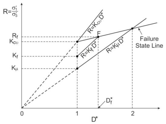
Figure 1.
Illustration of Rowe’s stress–dilatancy relationship for TXC.
Bolton [7] analyzed the results of the drained TXC and BXC tests for 17 different sands with various initial densities and by confining the pressures at failure, and proposes the following well-known relationships:
where and are the secant effective angles of the friction in TXC and BXC, respectively.
The relative dilatancy index is:
(In Bolton’s original formula, there are Q and R.)
The relative dilatancy index is a function of the initial density index () and the mean effective stress at failure, , expressed in kPa. It was found that the values, = 10 and = 1, offer a unique set of correlations for the dilatant behavior of many sands [7]. For the test results collected by Bolton, the mean effective stress at failure is ; therefore, there is no grain breakage effect. Bolton’s [7] relationships are correct for 0 < < 4. Therefore, , and 0° < < 12°. Those ranges of values, , are assumed in this study, and the density index can be obtained from the CPT or DMT results [31].
The general stress–plastic dilatancy relationship is obtained from the frictional state concept (FSC) developed by Szypcio [22], in the following forms:
where:
,
,
,
,
,
,
,
,
,
,
,
,
,
,
,
,
,
,
,
,
For conventional drained compression tests at constant, :
which represents the slope of the stress–plastic dilatancy line in the plane for a purely frictional state (α = 0, β = 1).
The stress ratio can be calculated from the following equation:
and the secant angle of friction, which is expressed in degrees, can be calculated from the equation:
Neglecting the elastic strain increments, the behavior of the stress–dilatancy of Toyoura sand for TXC at different initial densities and confining pressures ( 100 kPa) is shown in Figure 2 [32].
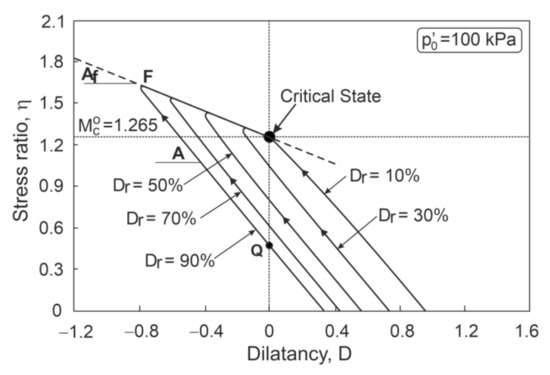
Figure 2.
Stress–dilatancy relationships for Toyoura sand (adopted from [32]).
For the pre-failure stage, the lines, , have the slopes, A, and intersect the vertical axis at Q, with the parameters, α > 0 and β > 1. More complex stress–plastic dilatancy relationships can also be observed in sand shear [26]. Usually, Points F, which represent failure states (Figure 2), lie almost on a straight line with a slope, , and intersect the vertical axis at the point representing the critical frictional state (). α and β are new soil parameters that express the combined effect of the anisotropy, the grain breakage, the non-coaxiality of the stress, and the strain increment tensors, as well as other undefined effects. The values of these parameters for various stages of shearing should be determined experimentally [26,27,28,29]. For TXC and TXE at failure, and , whereas for BXC, and , for sands without breakage effects [22,23,24,25,26]. The FSC assumes that for sands, [22]. It is also assumed that the critical state angle is independent of the deformation mode [8,23,33,34]. For most natural sands, the values, , range from 30° to 34° (Table 1).

Table 1.
Critical state friction angles for some sands.
The characteristic values of the stress–dilatancy relationship for the drained TXC, BXC, and TXE tests when is a constant stress path are presented in Table 2 [22,23,24,25].
Table 2.
Characteristic values of stress–dilatancy relationship for drained conditions at a constant stress path.
In this study, for clarity, the characteristic values at failure for TXC, BXC, and TXE are marked with the subscripts, c, b, and e, respectively (e.g., , , and and , , and ).
For the convenience of later consideration, we define:
where The plastic dilatancy can be expressed when the elastic parts of the strain increments are ignored by using the following equation:
3. Shear Strength of Sand for TXC, BXC, and TXE
3.1. Drained Triaxial Compression
For drained triaxial compression (TXC), and . At failure, elastic parts of the strain increments vanish; therefore:
where, without the breakage effects, and [22].
Comparing Equations (1) and (22) for , and [21,30], and , the following equation is obtained:
The relationships, , which were obtained by Horne [30], and the FSC, are shown in Figure 3.
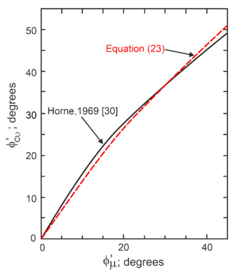
Figure 3.
The relationships (adapted from [30]).
For , and
is obtained from the FSC (Equation (22)) and Rowe’s theory (Equation (1)).
Assuming that, for the failure state, the stress ratios calculated from the FSC (Equation (22)) and Rowe’s theory (Equation (1)) are equal, the following equation is obtained:
We can see that for , , and for , , Equations (23) and (25) are equivalent.
By comparing Bolton’s Equations (9) and (11), we can write:
The friction angle calculated using Bolton’s Equation (26) and the FSC (Equation (22)) for , and are shown in Figure 4.
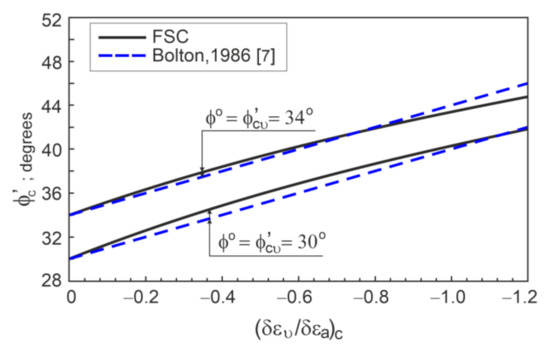
Figure 4.
The − relationships.
The values, which were calculated with the use of Equation (25), and the stress ratios (friction angle), which were calculated from Equations (1) and (22), are equal.
This proves the correctness of the FSC for drained triaxial compression. More proofs can be found in [23].
3.2. Plane Strain Conditions
For the plane strain conditions (BXC), the stress ratio at failure can be calculated using Rowe’s theory (Equation (1)), with .
By comparing Bolton’s Equations (10) and (11), we can derive the following equation:
The stress ratio calculated using the FSC depends on the intermediate principal stress (parameter ; angle ). The intermediate principal stress ( values) depends on the initial porosity, the contact of the belt plate [51], and the height-to-width ratio of the specimen [4].
Figure 5 shows some experimental values of as a function of . The values range from 0.18 (= 20.3°) to 0.35 (= 9.8°), with mean values of = 0.265 (. = 15.2°). Similar values were observed by Green and Reades [51], Tatsuoka et al. [54], and Pradhan et al. [55]. At the post-failure shearing stage, the value does not change [8,50].
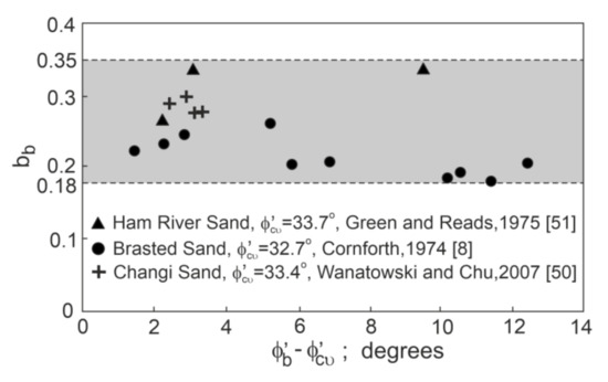
Figure 5.
The values for some sands at BXC.
For BXC, the friction angle can be calculated from Equation (16) using Equations (13) and (15). = 0; therefore, at failure:
and
For the BXC failure states, the experimental stress–dilatancy relationship is accurately described by the FSC equation (Equation (13)), with 0 and 1.4 [24]. (Table 1) depends on the Lode angles for the stresses ( or ) and the strain increments (). The effect of on the friction angle, (), for and which was calculated using the FSC, is shown in Figure 6.
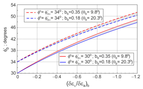
Figure 6.
Influence of on the sand strength for BXC.
For the observed ranges of , the maximum impact is less than 1°. The difference increases with a decrease in the strain increment ratio (), and it is almost independent of the critical state angle. Therefore, further analyses will be performed only for = 0.265 ( = 15.2°).
Figure 7 shows the relationship between and , which is calculated using the Rowe, Bolton, and FSC relationships.
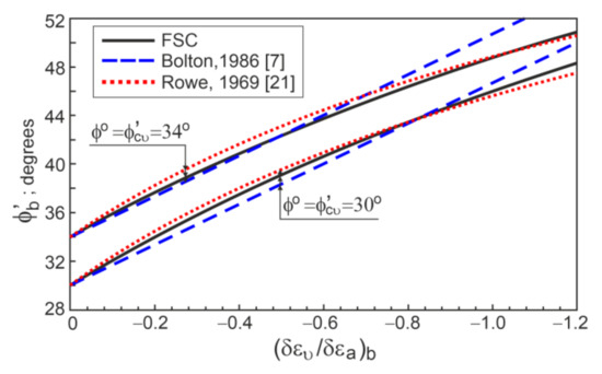
Figure 7.
The − relationships.
The values of the obtained from the Rowe and FSC relationships are very similar. The maximum difference is smaller than 0.5°. A good convergence of the values, which were calculated using the Bolton and FSC relationships, is obtained for . For , the values calculated using Bolton’s equation (Equation (27)) are slightly higher than those calculated using the FSC.
[7,8]; therefore, the relationship between and can be calculated using the FSC. The relationships between the and the which are calculated using the FSC, and which are obtained in some experiments [4,8,9,21,56,57,58,59], are shown in Figure 8.
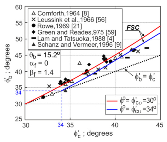
Figure 8.
Comparison of and for different sands.
It can be seen that the FSC correctly expresses the and relationship.
3.3. Drained Triaxial Extension
For the drained triaxial extension (TXE), Rowe’s equation (Equation (2)) is correct for [21]. As in TXC, by comparing the FSC and the Rowe’s stress ratios at the failure states, we can write:
The sand strength and dilatancy were not analyzed by Bolton [7] for TXE.
On the basis of the analysis of some of the results of the experimental TXC and TXE tests presented in the literature [8,57,58,59,60,61] (Figure 9), it is proposed that, for the same initial density and stress level at failure:
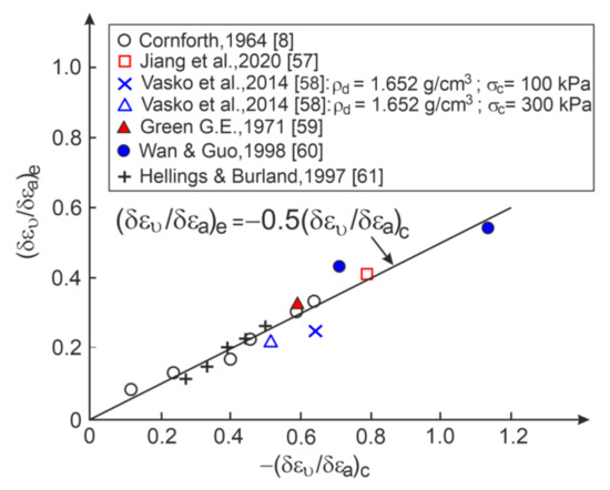
Figure 9.
Relationship between the strain increment ratio at failure for triaxial compression and triaxial extension.
For TXE, the friction angle can be calculated from the FSC equation (Equation (16)) by using Equations (13) and (15) and the values , , , , , and given in Table 1. The experimental and theoretical friction angles () for some TXE tests are shown in Figure 10.
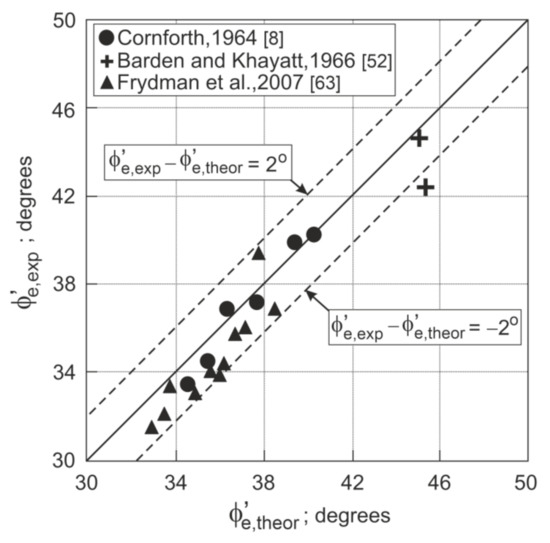
Figure 10.
for some TXE tests.
Most of the values of are in the range of ±2°. By using the FSC and the proposed relationship (Equation (31)), the difference between the and the can easily be calculated (Figure 11).
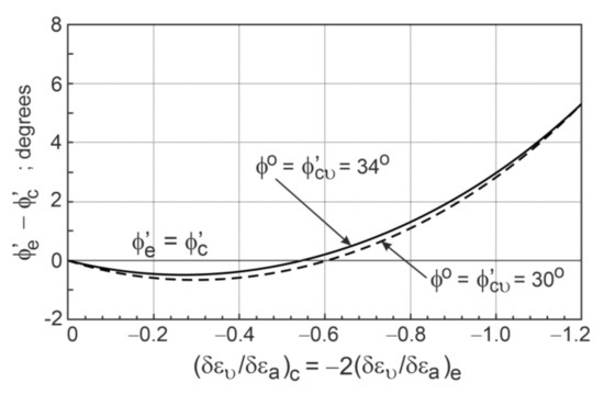
Figure 11.
The − relationships.
The difference is only slightly influenced by the critical state angle. For , the value is slightly smaller than the . For , the is higher than the . The difference between the and the increases with a decrease in the strain increment ratio, and for , it reaches about 5.5°. It is generally accepted that the friction angle for TXE is slightly higher than that for TXC [15,51,62,63].
4. Shear Strength of Sand for the General Condition
The friction angles for the drained TXC, BXC, and TXE tests, which were calculated using the FSC, where and for TXC and TXE, and , for BXC, and and , are correct. Therefore, we can express the shear strength of sand for TXC , BXC , and TXE as a function of and the strain increment ratio, .
The shear strength of sand can be calculated from Equation (16) using the stress ratio (η) and the dilatancy (D), which are expressed by Equations (13) and (18) for the known , , and , respectively.
The components of the dilatancy expressed by Equation (18) are:
- For TXC:
- For BXC:
- For TXE:
Assuming that the components of dilatancy, and , are bilinear functions of the parameter, we can write:
and
If the shear strength is not affected by the breakage and other undefined effects, the following can be assumed:
and
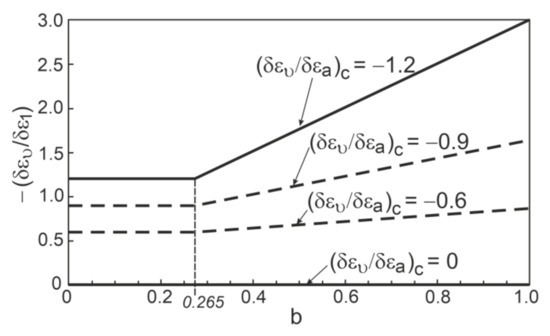
Figure 12.
Relationship between and .
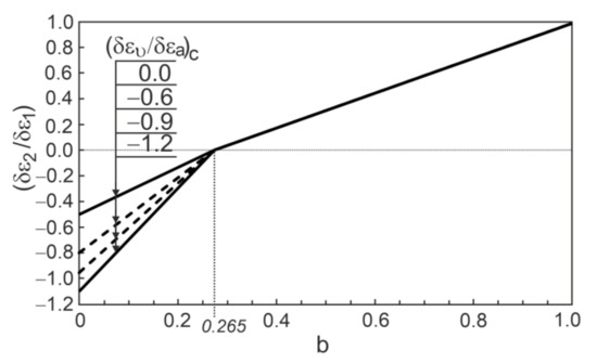
Figure 13.
Relationship between and .
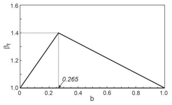
Figure 14.
Relationship between and for shear.
Thus, the dilatancy at failure in the general state can be expressed simply by the strain increment ratio,, for TXC.
The shear strength of sand can be calculated from Equation (16), for a known , using Equations (13), (15), (18), and (39)–(45).
Some failure criteria that are commonly known and used in engineering practice include the Mohr–Coulomb, Lade–Duncan [3], and Matsuoka–Nakai [2] criteria. The Mohr–Coulomb criterion assumes that the angle of friction is independent of the intermediate principal stress and it can be expressed as follows:
The Lade–Duncan criterion (1975) is expressed as:
whereas the Matsuoka–Nakai criterion can be formulated as:
where:
and in [64]:
The friction angle can be expressed using or and and .
The friction angles, which were calculated using the FSC, and the Lade–Duncan and Matsuoka–Nakai criteria for and 34°, ; −0.6, and −1.2 are shown in Figure 15. The Mohr–Coulomb criterion gives (for clarity, this is not shown in Figure 15).
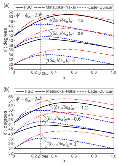
Figure 15.
Comparisons of friction angles calculated using different criteria: (a) for ; and (b) for .
The differences between the and the , which were calculated using different failure criteria and the FSC, are shown in Figure 16.
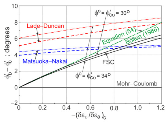
Figure 16.
The relationships.
Except for the Mohr–Coulomb criterion, for dilative sand behavior. The difference increases with the decrease in the strain increment ratio, . The difference, , which is calculated using the Matsuoka–Nakai and Lade–Duncan criteria, is also greater than 4° for non-dilative behavior, . This means that the critical friction angle for the BXC is much higher than for the TXC. For very dilative behavior, , the difference calculated using the FSC is higher than that obtained from the Matsuoka–Nakai criterion, and smaller than that obtained from Lade–Duncan criterion.
By comparing the Bolton’s relationships for TXC and BXC, the following equation can be written:
The differences calculated by using the FSC and Bolton’s relation are similar (Figure 16). The differences, , which were calculated using different failure criteria and the FSC, are shown in Figure 17.
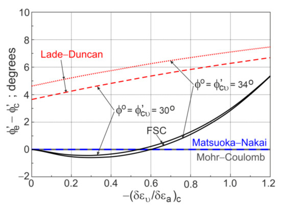
Figure 17.
The − relationships.
The Mohr–Coulomb and Matsuoka–Nakai criteria assume that . The difference, , which is calculated using the Lade–Duncan criterion, is higher than about 4° for non-dilative behavior, and increases for more dilative behavior, reaching around 7° for , . Using the FSC for not very dilative behavior, , , the difference ; and for very dilative behavior, , , the difference , reaching little more than 5° for , . The difference, ≈ 4°, is obtained from the Lade–Duncan criterion for the non-dilative behavior and it assumes that the critical state angle of friction for the TXE is much greater than that for the TXC. However, the experiments do not confirm this.
Ladd et al. [18] and Lade [12] collected many true triaxial test results for sand. Lade [12] analyzed the influence of the shear banding, the specimen slenderness ratio, the cross anisotropy, and the stability of the experimental technique on the sand strength. The analyzed data do not conform to one common failure criterion.
Kulhawy and Mayne [19] calculated the ratio, , on the basis of the test results collected by Ladd et al. [18]. The results are shown in Figure 18.
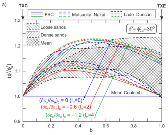
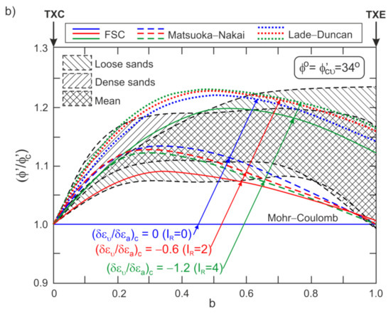
Figure 18.
Influence of intermediate principal stress on : (a) for ; and (b) for (adopted from [19]).
The ratios, were calculated using the Matsuoka–Nakai and Lade–Duncan criteria and the FSC for 30° and 34°, for non-dilative , , for moderate-dilative , , and for high-dilative, , , and the behaviors are also shown in Figure 18. For the Mohr–Coulomb criterion, the ratio, =1, is independent of the dilatancy. The effect of , , and on is small for the Matsuoka–Nakai and Lade–Duncan criteria. In contrast, the ratio, , which is calculated using the FSC, is very sensitive to the strain increment ratio, (dilatancy), and the critical friction angle (). For non-dilative behavior, , , , and =1 for the Mohr–Coulomb criterion. For the moderate-dilative (, ) and high-dilative (, ) behavior, the ratio values are similar to those calculated using the Matsuoka–Nakai and Lade–Duncan criteria, respectively.
5. Conclusions
The stress–dilatancy relationship at failure in the general state is correctly described by the equation obtained from the frictional state concept.
For the drained triaxial and biaxial compression states, the presented theoretical stress–dilatancy relationships are very similar to those given by Bolton.
Using the frictional state concept, the parameter of the Rowe model can be expressed by the critical state angle and the dilatancy at failure.
The dilatancy at failure in the general state is a function of the ratio of the volumetric and axial strain increments, , for triaxial compression.
The ratio of the angle of friction in the general state and the angle of friction in triaxial compression, which is calculated using the presented procedure, is correspondingly similar to that obtained from the Mohr–Coulomb, Matsuoka–Nakai, and Lade–Duncan criteria for non-dilated, moderately dilated, and highly dilated sands.
The authors strongly believe that future laboratory tests will confirm the correctness of the stress–dilatancy relationships presented in this paper and that they will be used to build new elasto-plasticity models for sands.
Author Contributions
Conceptualization, Z.S.; methodology, Z.S. and K.D.-S.; validation, K.D.-S. and J.M.; formal analysis, Z.S. and K.D.-S.; writing—original draft preparation, K.D.-S. and J.M.; writing—review and editing, K.D.-S. and Z.S.; visualization, K.D.-S.; supervision, K.D.-S., Z.S. and J.M. All authors have read and agreed to the published version of the manuscript.
Funding
This research was funded by the Ministry of Science and Higher Education (grant no. WZ/WB-IIL/7/2019) and the statutory fund of the Institute of Hydro-Engineering of the Polish Academy of Science.
Institutional Review Board Statement
Not applicable.
Informed Consent Statement
Not applicable.
Data Availability Statement
Not applicable.
Acknowledgments
The investigations were conducted at the Bialystok University of Technology (Poland) and the Institute of Hydro-Engineering of the Polish Academy of Science. Katarzyna Dołżyk-Szypcio would like to acknowledge the Institute of Hydro-Engineering of the Polish Academy of Science for enabling her to take up a scientific internship.
Conflicts of Interest
The authors declare no conflict of interest.
References
- Atkinson, J. The Mechanics of Soils and Foundations, 2nd ed.; Taylor & Francis Group: London, UK, 2007. [Google Scholar] [CrossRef]
- Matsuoka, H.; Nakai, T. Stress-Deformations and Strength Characteristics of Soils under Three Different Principal Stresses; Japan Society of Civil Engineers: Tokyo, Japan, 1974; Volume 232, pp. 59–74. [Google Scholar] [CrossRef]
- Lade, P.V.; Duncan, J.M. Elastoplastic Stress-Strain Theory for Cohesionless Soil. J. Geotech. Eng. Div. 1975, 101, 1037–1053. [Google Scholar] [CrossRef]
- Lam, W.K.; Tatsuoka, F. Effects of Initial Anisotropic Fabric and σ2 on Strength and Deformation Characteristics of Sand. Soils Found. 1988, 28, 89–106. [Google Scholar] [CrossRef]
- Liu, M.D.; Indraratna, B.N. General Strength Criterion for Geomaterials Including Anisotropic Effect. Int. J. Geomech. 2011, 11, 251–262. [Google Scholar] [CrossRef]
- Cao, W.; Wang, R.; Zhang, J.-M. Formulation of Anisotropic Strength Criteria for Cohesionless Granular Material. Int. J. Geomech. 2017, 17. [Google Scholar] [CrossRef]
- Bolton, M.D. The strength and dilatancy of sands. Géotechnique 1986, 35, 65–78. [Google Scholar] [CrossRef]
- Cornforth, D.H. Some Experiments on the Influence of Strain Conditions on the Shear Strength of Sand. Géotechnique 1964, 14, 143–167. [Google Scholar] [CrossRef]
- Schanz, T.; Vermeer, P.A. Angles of friction and dilatancy of sand. Géotechnique 1996, 46, 145–151. [Google Scholar] [CrossRef]
- Lade, P.V.; Lee, K.L. Engineering Properties of Soils; Report UCLA-ENG-7652; University of California: Los Angeles, CA, USA, 1976. [Google Scholar]
- Das, B.M. Advanced Soil Mechanics, 3rd ed.; Taylor & Francis Group: London, UK; New York, NY, USA, 2008. [Google Scholar]
- Lade, P.V. Assessment of test data for selection of 3-D failure criterion for sand. Int. J. Numer. Anal. Meth. Geomech. 2006, 30, 307–333. [Google Scholar] [CrossRef]
- Yamamuro, J.A.; Lade, P.V. Drained Sand Behaviour in Axisymmetric Tests at High Pressures. J. Geotech. Eng. 1996, 122, 109–119. [Google Scholar] [CrossRef]
- Corfdir, A. Sulem, J. Comparison of extension and compression triaxial tests for dense sand and sandstone. Acta Geotech. 2008, 3, 241. [Google Scholar] [CrossRef]
- Green, G.E.; Bishop, A.W. A Note on the Drained Strength of Sand Under Generalized Strain Conditions. Géotechnique 1969, 19, 144–149. [Google Scholar] [CrossRef]
- Mesdary, M.S.; Sutherland, H.B. Correspondence to “A Note on the Drained Strength of Sand Under Generalized Strain Conditions. Green, G.E., Bishop, A.W., Géotechnique 1969, 19, 144–149“. Géotechnique 1970, 20, 210–212. [Google Scholar] [CrossRef]
- Ko, H.Y.; Scott, R.F. Deformation of sand at failure. J. Soil Mech. Found. Div. 1968, 94, 883–898. [Google Scholar] [CrossRef]
- Ladd, C.C.; Foote, R.; Ishihara, K.; Schlosser, F.; Poulos, H.G. Stress-Deformation and Strength Characteristics. In Proceedings of the 9th International Conference on Soil Mechanics and Foundation Engineering, Tokyo, Japan, 11 July 1977; Volume 2, pp. 421–494. [Google Scholar]
- Kulhawy, F.H.; Mayne, P.W. Manual on Estimating Soil Properties for Foundation Design; EL-6800 Research Project 1493-6; Cornell University: New York, NY, USA, 1990. [Google Scholar]
- Taylor, D.W. Fundamentals of Soil Mechanics; John Wiley and Sons: New York, NY, USA, 1948. [Google Scholar]
- Rowe, P.W. The Relationship Between the Shear Strength of Sands in Triaxial Compression, Plane Strain and Direct Shear. Gèotechnique 1969, 19, 75–86. [Google Scholar] [CrossRef]
- Szypcio, Z. Stress-dilatancy for soils. Part I: The frictional state theory. Studia Geotech. Mech. 2016, 38, 51–57. [Google Scholar] [CrossRef]
- Szypcio, Z. Stress-dilatancy for soils. Part II: Experimental validation for triaxial tests. Studia Geotech. Mech. 2016, 38, 59–65. [Google Scholar] [CrossRef]
- Szypcio, Z. Stress-Dilatancy for Soils. Part III: Experimental Validation for the Biaxial Condition. Studia Geotech. Mech. 2017, 3, 73–80. [Google Scholar] [CrossRef][Green Version]
- Szypcio, Z. Stress-Dilatancy for Soils. Part IV: Experimental Validation for Simple Shear Conditions. Studia Geotech. Mech. 2017, 39, 81–88. [Google Scholar] [CrossRef][Green Version]
- Dołżyk-Szypcio, K. Stress-Dilatancy Relationship of Erksak Sand under Drained Triaxial Compression. Geosciences 2020, 10, 353. [Google Scholar] [CrossRef]
- Szypcio, Z. Stress-dilatancy of gravel for triaxial compression tests. Ann. Warsaw Univ. Life Sci. SGGW Land Reclam. 2018, 50, 119–128. [Google Scholar] [CrossRef]
- Dołżyk-Szypcio, K. Stress-dilatancy relationship for railway ballast. Studia Geotech. Mech. 2018, 40, 79–85. [Google Scholar] [CrossRef]
- Dołżyk-Szypcio, K. Stress-Dilatancy of Rounded and Angular Rockfill Materials. IOP Conf. Ser. Earth Environ. Sci. 2019, 221, 1–7. [Google Scholar] [CrossRef]
- Horne, M.R. The Behaviour of an Assembly of Rotund, Rigid, Cohesionless Particles. Part III. Proc. R. Soc. London Ser. A Math. Phys. Sci. 1969, 310, 21–34. [Google Scholar] [CrossRef]
- Jamiołkowski, M.; Lo-Presti, D.C.F.; Manassero, M. Evolution of Relative Density and shear Strength of Sands from CPT and DMT. In Proceedings of the Symposium on Soil Behavior and Soft Ground Construction Honoring Charles C. “Chuck” Ladd, Boston, MA, USA, 5–6 October 2001; ASCE Geotechnical Special Publication No.119. pp. 201–238. [Google Scholar] [CrossRef]
- Yang, J.; Li, X.S. State-Dependent Strength of Sands from the Perspective of United Modeling. J. Geotech. Geoenviron. Eng. 2004, 130, 186–198. [Google Scholar] [CrossRef]
- Hanna, A.M.; Masoud, N.; Youssef, H. Prediction of plane strain angles of shear resistance from triaxial tests results. In Prediction and Performance in Geotechnical Engineering; University of Calgary: Calgary, AB, Canada, 1987; pp. 369–376. [Google Scholar]
- Schanz, T. Zunmodellierung des Mechnischenverhaltens von Reibungsmaterlean; Vermeer, P.A., Ed.; Institute fur Geotechnik, Universitat Stuttgart: Stuttgart, Germany, 1998; Volume 45. [Google Scholar]
- Konrad, J.-M.; Watts, B.D. Undrained shear strength for liquefaction flow failure analysis. Can. Geotech. J. 1995, 32, 783–794. [Google Scholar] [CrossRef]
- Olsen, S.M.; Stark, T.D. Use of laboratory data to confirm yield and liquefied strength ratio concepts. Can. Geotech. J. 2003, 40, 1164–1184. [Google Scholar] [CrossRef]
- Sun, Y.; Sumelka, W.; Gao, Y. Advantages and limitations of an α-plasticity model for sand. Acta Geotech. 2020, 15, 1423–1437. [Google Scholar] [CrossRef]
- Been, K.; Jefferies, M.G.; Hachey, J. The critical states of sands. Géotechnique 1991, 41, 365–381. [Google Scholar] [CrossRef]
- Riemer, M.F.; Seed, R.B.; Nicholson, P.G.; Jong, H.L. Steady State Testing of Loose Sands: Limiting Minimum Density. J. Geotech. Eng. 1990, 116, 332–337. [Google Scholar] [CrossRef]
- Sasitharan, S.; Robertson, P.K.; Sego, D.C.; Morgenstern, N.R. State-boundary surface for very loose sand and its practical implications. Can. Geotech. J. 1994, 31, 321–334. [Google Scholar] [CrossRef]
- Riemer, M.F.; Seed, R.B. Factors Affecting Apparent Position of Steady-State Line. J. Geotech. Geoenviron. Eng. 1997, 123, 281–288. [Google Scholar] [CrossRef]
- Ishihara, K. Liquefaction and flow failure during earthquakes. Géotechnique 1993, 43, 351–415. [Google Scholar] [CrossRef]
- Chu, J.; Lo, S.C.R. On the Measurement of Critical State Parameters of Dense Granular Soils. Geotech. Test. J. 1993, 16, 27–35. [Google Scholar] [CrossRef]
- Prearo, C. Determination of Cyclic Resistance of Clean Sands from Cone Penetration Test Based on State Parameter. Ph.D. Thesis, University of Ferrara, Ferrara, Italy, 2015. [Google Scholar]
- Yu, H.S.; Khong, C.D.; Wang, J.; Zhang, G. Experimental evaluation and extension of a simple critical state model for sand. Granul. Matter 2005, 7, 213–225. [Google Scholar] [CrossRef]
- Ling, H.I.; Yang, S. Unified Sand Model Based on the Critical State and Generalized Plasticity. ASCE J. Eng. Mech. 2006, 132, 1380–1391. [Google Scholar] [CrossRef]
- Wang, J. The Stress-Strain and Strength Characteristics of Portaway Sand. Ph.D. Thesis, University of Nottingham, Nottingham, UK, 2005. [Google Scholar]
- Pestana, J.M.; Nikolinakou, M.; Whittle, A.J. Selection of material parameters for sands using MIT-SI model. In Soil Constitutive Models. Evaluation, Selection, and Calibration; Yamamuro, J.A., Kaliakin, Y.N., Eds.; ASCE Geotechnical Special Publication No. 128; ASCE: Reston, Virginia, 2005; pp. 425–439. [Google Scholar]
- Hettler, A.; Vardoulakis, I. Behaviour of dry sand tested in a large triaxial apparatus. Géotechnique 1984, 34, 183–197. [Google Scholar] [CrossRef]
- Wanatowski, D.; Chu, J. Static liquefaction of sand in plane strain. Can. Geotech. J. 2007, 44, 299–313. [Google Scholar] [CrossRef]
- Green, G.E.; Reades, D.W. Boundary condition, anisotropy and sample shape effects on the stress-strain behaviour of sand in triaxial compression and plane strain. Géotechnique 1975, 25, 333–356. [Google Scholar] [CrossRef]
- Barden, L.; Khayatt, A.J. Incremental Strain Rate Ratios and Strength of Sand in the Triaxial Test. Gèotechnique 1966, 16, 338–357. [Google Scholar] [CrossRef]
- Fern, J.; Soga, K.; Sakanoue, T. Modelling the Shear Strength and Dilatancy of Dry Sand in Triaxial Compression Tests. Geomechanics from Micro to Macro; Soga, K., Kumar, K., Biscontin, G., Kuo, M., Eds.; CRC Press: Boca Raton, FL, USA; Taylor & Francis Group: London, UK, 2015; Volume 2, pp. 673–678. [Google Scholar]
- Tatsuoka, F.; Sakamoto, M.; Kawamura, T.; Fakushima, S. Strength and deformation characteristics of sand in plane strain compression at extremely low pressures. Soils Found. 1986, 26, 65–84. [Google Scholar] [CrossRef]
- Pradhan, T.B.S.; Tatsuoka, F.; Horii, N. Strength and deformation characteristics of sand in torsional simple shear. Soils Found. 1988, 28, 131–148. [Google Scholar] [CrossRef]
- Leussink, H.; Blinde, A.; Abel, P.-G. Versuche über die Sohldruckverteilung unter Starren Gründungskörpern auf Kohäsionslosem Sand; Veröffentlichungen des Instituts für Bodenmechanik und Grundbau der Technischen Hochschule Fridericiana in Karlsruhe: Karlsruhe, Germany, 1966. [Google Scholar]
- Jiang, M.; Zhang, A.; Shen, Z. Granular soils: From DEM simulation to constitutive modeling. Acta Geotech. 2020, 15, 1723–1744. [Google Scholar] [CrossRef]
- Vasko, A.; El Ghoraiby, M.; Manzari, M.T. An Investigation into the Behaviour of Ottawa Sand under Monotonic and Cyclic Shear Tests; Department of Civil and Environmental Engineering, George Washington University: Washington, DC, USA, 2014. [Google Scholar]
- Green, G.E. Strength and deformation of sand measured in an independent stress control cell. In Proceedings, Roscoe Memorial Symposium on Stress-Strain Behaviour of Soil; Cambridge University: Cambridge, UK, 1971; pp. 285–323. [Google Scholar]
- Wan, R.G.; Guo, P.J. A Simple Constitutive Model for Granular Soils: Modified Stress—Dilatancy Approach. Comput. Geotech. 1998, 22, 109–133. [Google Scholar] [CrossRef]
- Hellings, J.E.; Burland, J.B. Strength and deformation characteristics of a silty sand. In Proceedings of the Fourteenth International Conference on Soil Mechanics and Foundations Engineering, Hamburg, Germany, 6–12 September 1997; pp. 303–306. [Google Scholar]
- Reades, D.W.; Green, G.E. Independent stress control and triaxial extension tests on sand. Géotechnique 1976, 26, 551–576. [Google Scholar] [CrossRef]
- Frydman, S.; Telesnick, M.; Nawatha, H.; Schwartz, K. Stress-dilation of undisturbed sand samples in drained and undrained triaxial shear. Soils Found. 2007, 47, 27–32. [Google Scholar] [CrossRef]
- Mortara, G. A new yield and failure criterion for geomaterials. Géotechnique 2008, 58, 125–132. [Google Scholar] [CrossRef]


Publisher’s Note: MDPI stays neutral with regard to jurisdictional claims in published maps and institutional affiliations. |
© 2022 by the authors. Licensee MDPI, Basel, Switzerland. This article is an open access article distributed under the terms and conditions of the Creative Commons Attribution (CC BY) license (https://creativecommons.org/licenses/by/4.0/).