Article

Numerical Study on Flow and Heat Transfer of Supercritical Hydrocarbon Fuel in Curved Cooling Channel

1
School of Mechanical Engineering and Automation, Harbin Institute of Technology (Shenzhen), Shenzhen 518071, China
2
Science and Technology on Combustion, Internal Flow and Thermo-Structure Laboratory, Northwestern Polytechnical University, Xi’an 710072, China
3
College of Aerospace Science and Engineering, National University of Defence Technology, Changsha 410073, China
*
Author to whom correspondence should be addressed.
Appl. Sci. 2022, 12(5), 2356; https://doi.org/10.3390/app12052356
Submission received: 10 December 2021 / Revised: 16 January 2022 / Accepted: 19 January 2022 / Published: 24 February 2022
(This article belongs to the Special Issue Heat Exchangers: Latest Advances and Prospects)

Abstract

:
The fluid flow and heat transfer of hydrocarbon fuel play a significant role in developing regenerative cooling technology for advanced aeroengines. Numerical simulations have been conducted to investigate the flow and heat transfer characteristics of China RP-3 aviation kerosene with pyrolysis in a 3D, 90° bend, square cooling channel around the cavity flame-holder of a scramjet. A chemical kinetic model, composed of 18 species and 24 reactions, was adopted to simulate the fuel pyrolysis process. Results indicate that the secondary flow enhances the mixing of the fluid, thus, the transports of heat and components are improved between the near-wall region and main flow field in the curved channel. Compared with a straight cooling channel, fuel conversion and heat-absorbing capacity are higher, and the heat transfer is effectively enhanced in a curved cooling channel. In addition, with the increasing inlet mass flow rate and the decreasing radius of curvature, the velocity of the secondary flow increases. The heat and components are easily transferred from the near-wall region to the main flow. The non-uniformities of fuel temperature and conversion at the cross section decreases, which is helpful for improving the utilization of the level of fuel heat-absorbing capacity, and beneficial for enhancing the heat transfer.

1. Introduction

Scramjets are the most promising power devices in air-breathing hypersonic flight, which has received increasing attention. As the flight Mach number increases, the thermal protection of combustion chambers becomes a critical issue due to its extremely thermal environment [1,2,3,4,5]. Active regenerative cooling technology is proposed as the most feasible thermal protection method, in which the hydrocarbon fuel of a scramjet is used as a coolant [2,6,7]. During the cooling process, hydrocarbon fuel provides not only physical heat sink but also additional chemical heat sink through endothermic reactions (also known as thermal cracking or pyrolysis [8]).
Much research has been conducted on the flow and heat transfer characteristics of hydrocarbon fuels with the consideration of fuel pyrolysis under supercritical conditions in straight cooling channels. Hou et al. [9] and Meng et al. [10] investigated the heat transfer and thermal cracking behaviors of aviation kerosene. Zhao [11] and Ward [12] studied the pressure effect on heat transfer and fuel pyrolysis. Feng et al. [13,14] quantitatively analyzed the coupling relationship between the flow and pyrolysis reactions of hydrocarbon fuel in a mini channel. Results reveal that, in a regenerative cooling system, the flow field and heat transfer are significantly influenced by fuel pyrolysis.
A curved channel is an important component and widely applied in the design of regenerative cooling technology, such as the cavity flame-holder, near the nozzle throat region and the connection area of a combustion chamber [15]. In curved cooling channels, the secondary flow is induced by the centrifugal force in the cross section [16,17]. Some literature [15,18,19,20,21,22] has been published on the influence of secondary flow on the flow field and heat transfer of hydrocarbon fuels without fuel pyrolysis. Results revealed that, compared to straight channels, the secondary flow enhanced flow mixing and promoted heat transfer in curved channels. However, these investigations ignore the pyrolysis process of hydrocarbon fuels.
Until recently, there was a lack of knowledge about the effect of curved configurations on flow field, heat transfer, and fuel pyrolysis. In a relevant paper, Jing et al. [23] investigated the flow and heat transfer characteristics of aviation kerosene in sharply curved cooling channels at supercritical pressures using a simplified pyrolytic reaction mechanism. Sun et al. [24] numerically studied the effect of centrifugal force on the flow field, heat, and mass transfers of hydrocarbon fuel in a helical channel, using the PPD model [25]. However, the results carried out by the PPD model were limited to situations with low fuel conversion. The reason is that many important secondary chemical reactions were ignored. In a curved channel (e.g., a surrounding cavity flame-holder or nozzle throat), the wall heat flux is very high, and a secondary reaction occurs, which makes the conversion of hydrocarbon fuel exceed the mildly cracked regime [26]. The secondary chemical reaction significantly influences the flow and heat transfer of supercritical hydrocarbon fuel in cooling channels [27]. However, there is little information available in the literature about the flow and heat transfer characteristics of hydrocarbon fuel with secondary reactions in curved cooling channels.
In this paper, numerical studies are carried out to analyze the flow and heat transfer characteristics of supercritical China RP-3 aviation kerosene under a wide range of fuel pyrolysis conditions in a 3D rectangular curved cooling channel. The detailed chemical reaction mechanism of RP-3 in Ref. [28] is adopted to simulate the fuel pyrolysis process. In addition, the influence of mass flow rate and curvature on flow and heat transfer in curved cooling channels is also investigated. The numerical model and its validation are described in Section 2. The model setup for the simulation is presented in Section 3. The characteristics of flow and heat transfer are displayed in Section 4. Then, heat transfer and fuel pyrolysis in curved channels at different mass flow rates and curvatures are investigated. Finally, the conclusions of this article are presented in Section 5.

2. Materials and Methods

2.1. Governing Equations and Solution Method

This numerical study was based on finite volu me analysis software and user-defined functions. In the fluid region, the conservation equations of mass, momentum, energy, and species mass fractions were numerically solved to study the heat transfer and endothermic fuel pyrolysis of the China RP-3 aviation kerosene at a supercritical pressure.
( ρ U ) = 0 ,
( ρ U U ) P τ = S M ,
( ρ U H ) λ e f f T ( τ e f f U ) = 0 ,
( ρ U Y i ) ρ D i , m , e f f Y i = R i ,
where ρ, U , p, τ, H, T and D are the density, velocity, pressure, viscous stress, enthalpy, temperature, and diffusion coefficient of the fluid, respectively. SM is the source term of the chemical reaction, λ is the thermal conductivity, Yi is the mass fraction of specie i, and R is the molar gas constant. The subscripts m and eff represent the mixture and effective parameter.
In the solid region, the heat conduction equation is numerically solved:
( λ T ) = 0 ,
where λ is the thermal conductivity of the solid wall. In addition, the temperature and heat flow boundary conditions at the interface between fluid domain and solid domain were set as follows to meet the continuity conditions:
T w , s = T w , f q w , s = q w , f ,
For the mass diffusion coefficient, Fuller’s empirical formula was used at first to obtain the binary mass diffusion coefficient Dij at low pressure:
D i j = 0.00143 T 1.75 P M i j 1 / 2 [ ( v ) i 1 / 3 + ( v ) j 1 / 3 ] ,
where Mij is the mixed molar mass of species i, and species j; v is the diffusion volume.
Then, the effect of pressure was considered through the corresponding-states method suggested by Takahashi, as shown below:
D i j p ( D i j p ) + = f ( T r , p r ) ,
where superscript + indicates the value under low pressure; Tr and pr are the comparison temperature and pressure, respectively.
Finally, based on the binary diffusion coefficient, the effective diffusion coefficient was calculated by the following formula:
D i , m = 1 x i j i x i / D i j ,
where xi is the mole fraction of species i.
In this paper, κ-ω SST turbulent model was adopted to calculate the internal turbulent flow and heat transfer for its high accuracy and good numerical stability to the boundary [29,30]. The fuel density was calculated with the Peng–Robinson equation of state because the physical properties of fuel change dramatically with temperature under supercritical conditions [31,32]:
P = R T V b a V + 2 b V b 2 ,
where V is the volume, and a, b are parameters.
The empirical method proposed by Chung was selected to estimate viscosity and thermal conductivity of hydrocarbon fuel [33]. The calculation method of the above thermophysical properties was entered into the commercial CFD software FLUENT through the user-defined function UDF. In the numerical calculation, the solver was based on the finite-volume scheme, and the SIMPLEC algorithm.

2.2. Chemical Kinetics Model

The typical hydrocarbon fuel, HF-I, a commercial China RP-3 aviation kerosene, was selected as the coolant. This paper used the detailed chemical kinetic model of China RP-3 aviation kerosene [27], which contains 18 species and 24 reactions, and is suitable for a wide range of operating conditions. The numerical model used to simulate the fluid flow, heat transfer, and fuel pyrolysis of RP-3 under supercritical conditions was verified in our previous work [34]. The results show a good agreement with experiment data of the fuel bulk temperature and conversion of RP-3.

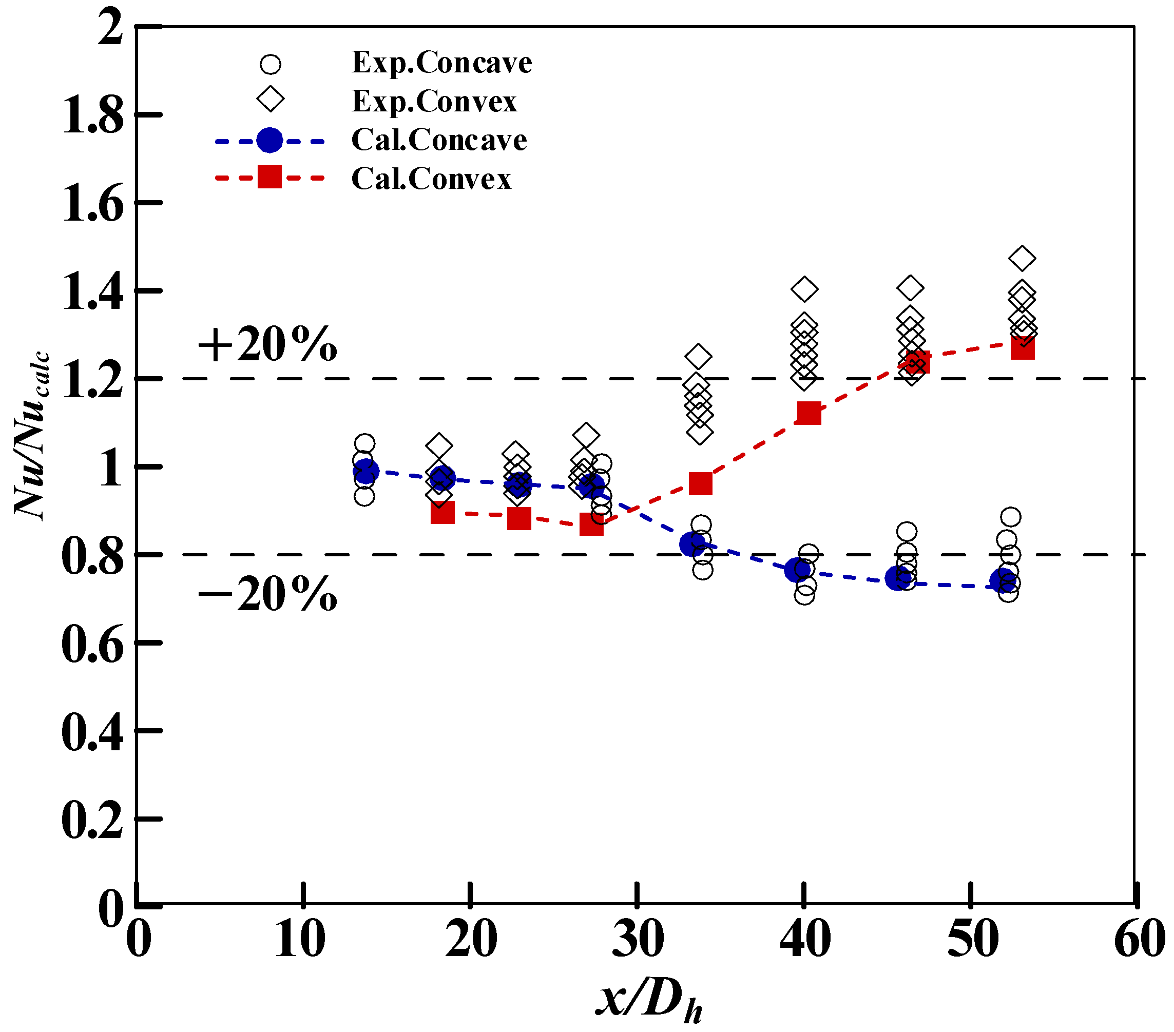
2.3. Validation of Numerical Model
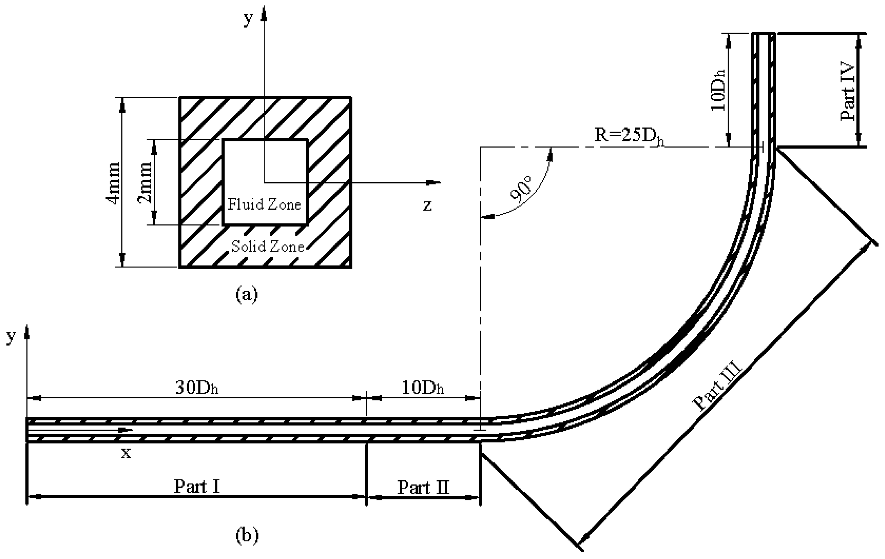
Model validations were further conducted in a curved channel based on the experimental data of supercritical nitrogen heat transfer obtained by Michael L. Meyer at NASA Lewis Research Center [35]. The curved channel with a cross-sectional aspect ratio of 1 and a 45° bend with 137 mm mean radius in the heated portion was adopted for model validation. The inside and outside dimensions of the square channel were 4.14 mm × 4.14 mm and 6.17 mm × 6.17 mm, respectively. The inlet velocity was 21.94 m/s, the inlet temperature of fuel was 280 K, the back pressure was 8.3 MPa, and the heat flux was 0.28 MW/m2.
The experimental heat transfer data and numerical results are described in Figure 1. Here, the Nusselt number, Nu, is the experimental Nusselt number, which is calculated by its definition, and the Nusselt number calculation, Nucalc, is the reference Nusselt number, which was obtained by a semi-empirically developed equation [36]:
N u c a l c = 0.023 Re b 0.8 Pr b 0.4 ( T w T b ) 0.3 ,
where Tb is the bulk fluid temperature, and Tw is the wall temperature. Re and Pr are the Reynolds number and the Prandtl number, respectively.
In the straight heat section (0 < x/Dh < 28), the maximum discrepancy of the ratio was less than 20%, which was within the uncertainty of the semi-empirical model. In the curved heat section (28 < x/Dh < 53.77), the discrepancy of the experimental data was greater than the numerical data, which is because the experimental data considered the effect of the electrical power input and the cooling enthalpy gain [36]. Very good agreements between experimental data and numerical results can be observed in Figure 1. Therefore, the numerical model is suitable to anticipate the heat transfer characteristics in a curved channel under supercritical conditions.

3. Model Setup

The cavity is an efficient flame-holding structure in the scramjet engine combustor [37] and is illustrated in Figure 2. In this study, a typical cooling channel around the leading edge of the cavity was selected as the study object. The geometry of the cooling channel for numerical simulation is shown in Figure 3 [38]. The inside and outside dimensions of the rectangular channel were 2 mm × 2 mm and 4 mm × 4 mm, respectively. Therefore, its hydraulic diameter Dh was 2 mm. The rectangular cooling channel consisted of four parts. The first part (Part I) was a straight section with a length of 30Dh to provide fully developed turbulent flow. The second part (Part II) was a straight section with a length of 10Dh to provide a developed thermal boundary layer. The third part (Part III) was a 90° curved channel with a radius of 25Dh. The last part (Part IV) was a straight outlet section with a length of 10Dh, which was used to eliminate the curvature effect. The heating section (Part II, Part III, and Part IV) was heated from the concave side, with a constant heat flux of 5 MW/m2 imposed on the external wall. The inlet mass flow rate of hydrocarbon fuel was 1 g/s, and the inlet temperature was 700 K. The back pressure was set to be 3 MPa.

4. Results and Discussion

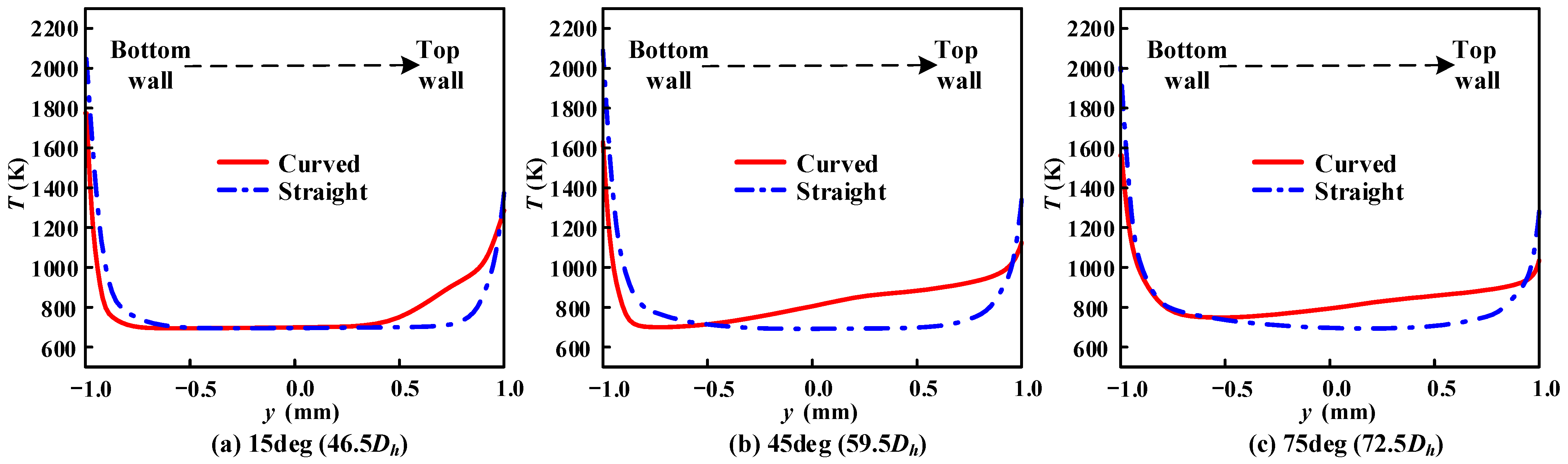
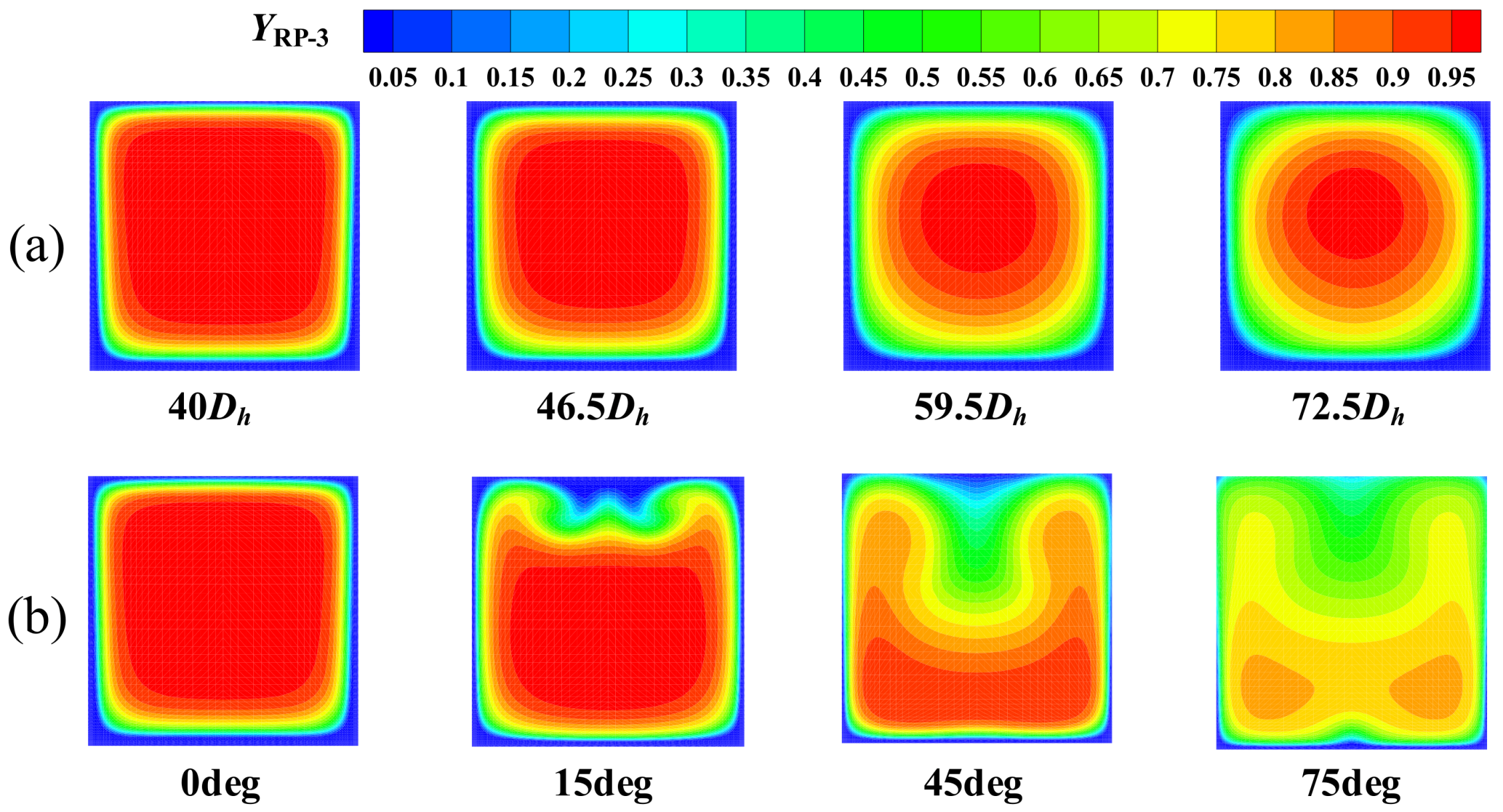
4.1. Effect of Secondary Flow on Pyrolysis and Heat Transfer

According to the previous analysis, the secondary flow in a curved channel enhances the fluid mixing and thermal exchange. In this paper, a case was also calculated in a straight channel for the purpose of comparison. The fuel conversion and heat transfer coefficient were numerically conducted in a straight channel and a curved channel to analyze the effect of the secondary flow on pyrolysis and heat transfer. The sectional geometry and boundary conditions of the straight channel were consistent with the curved channel, except that the bending radius is infinite.
The conversion of RP-3, ZRP-3, is defined as [39]:
Z RP - 3 = ( 1 A ρ u Y RP - 3 d A A ρ u d A ) × 100 % ,
where u is the velocity of fluid, and A is the surface area of the channel.
The distributions of fuel temperature and conversion at the cross sections of 0°, 15°, 45°, and 75° in the curved cooling channel, and at the same positions in the straight cooling channel, are presented in Figure 4, Figure 5, Figure 6 and Figure 7. The cooling channel was made of alloy and had high thermal conductivity. Although the channel was one-side-heated, the temperature of the hydrocarbon fuel in the near-wall regions increased first. Due to the higher fluid temperature, the fluid in the near-wall region had a higher chemical reaction rate than that in the main flow in both kinds of channels. Moreover, under the action of molecular viscous force, the hydrocarbon fuel in the near-wall region had a smaller axial velocity and longer residence time than that in the main flow. Therefore, in both curved and straight channels, the fuel conversion was high in the near-wall region and low in the main flow.
However, in the curved channel, the secondary flow pattern appeared in cross sections because of the centrifugal force, as shown in Figure 8. The secondary flow drove the fluid with low velocity near the wall inward, while the fluid with high velocity in the main flow swept outward [40]. The intensity of the secondary flow can be characterized by the secondary flow velocity [40], which is calculated as V S e c = ( u y ) 2 + ( u z ) 2 .
In the curved cooling channel, the high-temperature fluid in the near-wall region moved to the main flow due to the secondary flow. The fuel in the central region flowed towards the wall, as shown in Figure 8. The secondary flow transferred energy and components from the near-wall region to the main flow, and the radial heat and mass transfers were promoted. Therefore, compared with the straight cooling channel, the fuel in the curved cooling channel absorbed more heat. Meanwhile, due to the secondary flow, the main flow temperature increased faster in the curved cooling channel (as shown in Figure 5), and the chemical reaction rate was larger. Fuel conversion in the main flow of the curved channel was higher, as shown in Figure 7. Moreover, as the secondary flow enhanced mass transfer, the non-cracked hydrocarbon fuel in the main flow was pushed to the near-wall region, and the pyrolytic products in the near-wall region were transported to the main flow, and more hydrocarbon fuel underwent pyrolysis. For these two reasons, in the curved cooling channel, fuel conversion was higher, and the chemical heat absorption was larger, as shown in Figure 7 and Figure 9. At the outlet, the average fuel conversion of the curved channel was 34.25%, and that of the straight channel was 27.17%.
The above discussions show different distributions of fuel temperature and conversion between curved and straight cooling channels. Fuel temperature and conversion distributions are closely related to heat transfer. Thus, a comparative analysis of the heat transfer coefficient of curved and straight cooling channels is carried out. The heat transfer coefficient h is defined as [38]:
h = q T w T b ,
where q is the wall heat flux. The bulk fuel temperature, Tb, is defined as follows [38]:
T b = A ρ u C P T d A A ρ u C P d A ,
where Cp is the specific heat capacity.
The secondary flow promoted the heat and mass transfers of the hydrocarbon fuel. The fuel conversion and heat-absorbing capacity were higher in the curved cooling channel than those of the straight cooling channel. Therefore, as shown in Figure 10, the heat transfer coefficient in the curved cooling channel was higher. At the outlet of the curved section, the heat transfer coefficient increased by around 90%. Based on the above analysis, the secondary flow can effectively promote the heat and mass transfers of fuel and improve the cooling efficiency of a cooling channel.

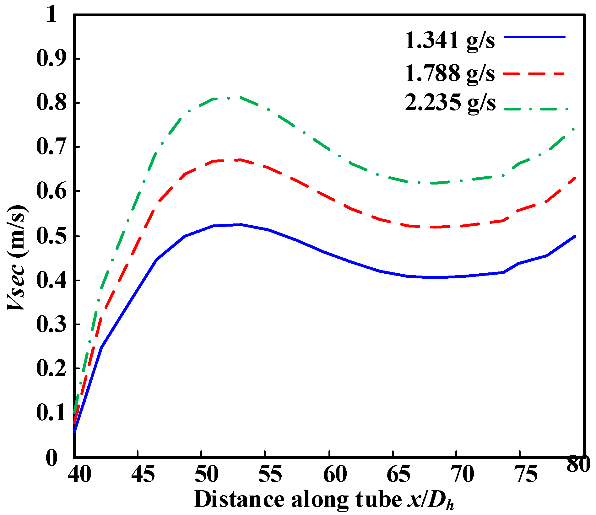
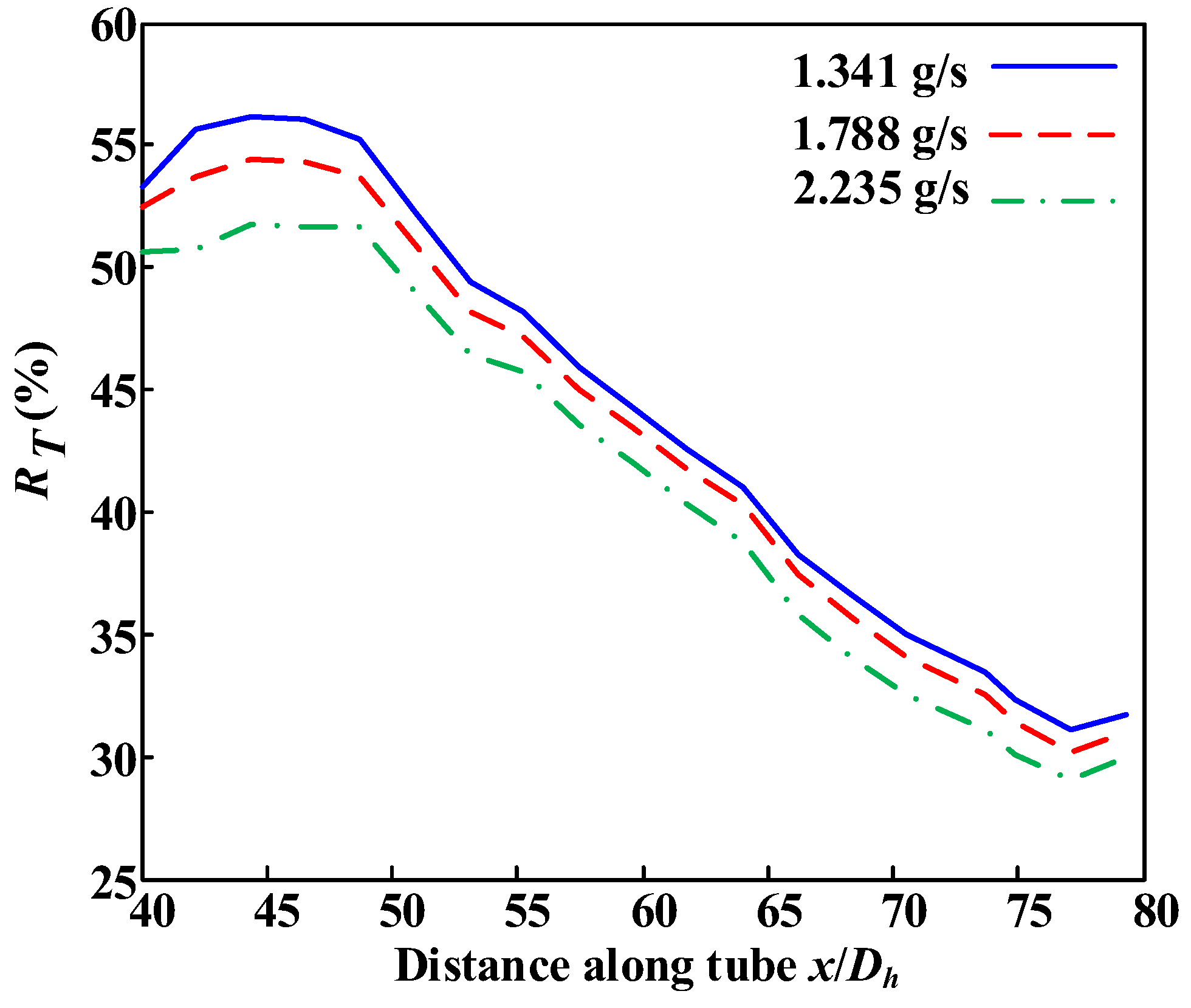
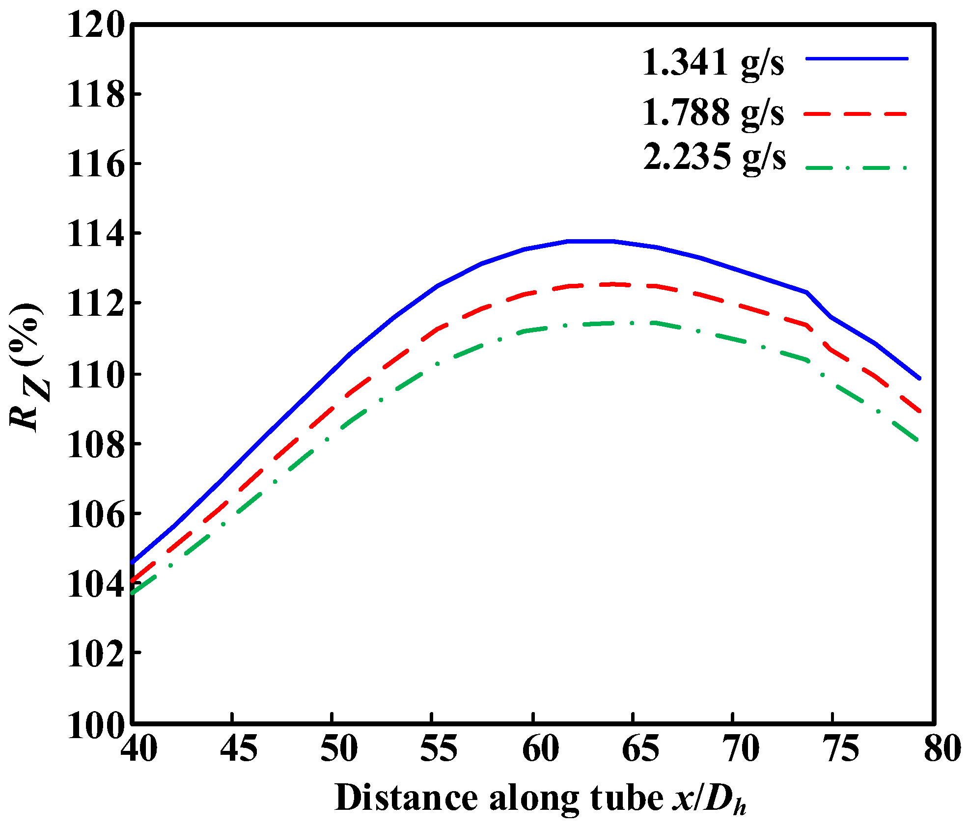
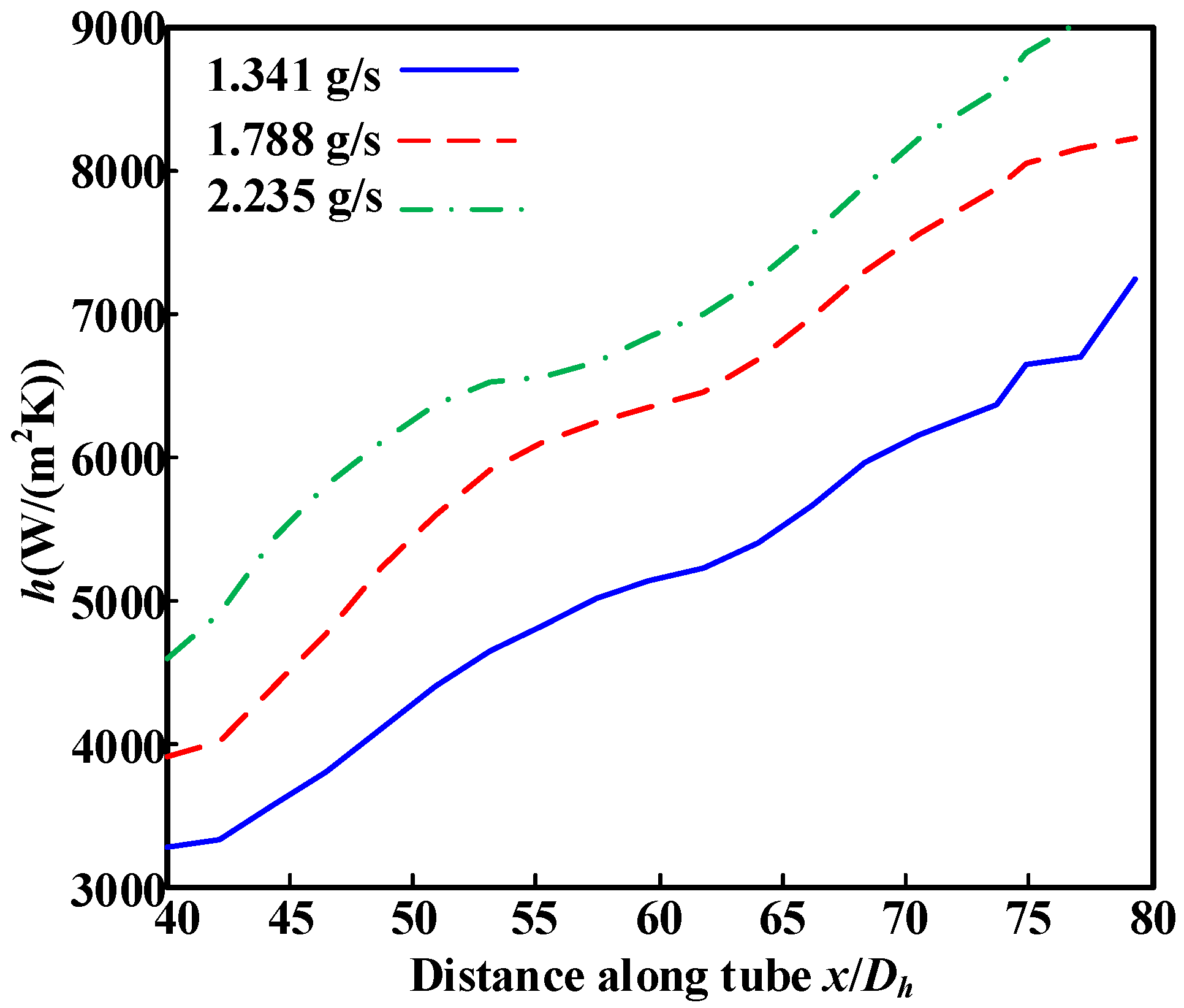
4.2. Effect of Mass Flow Rate on Heat and Mass Transfers in the Curved Cooling Channel

In the curved channel, the centrifugal force and secondary flow were directly proportional to the inlet mass flow rate of fuel. The change of the inlet mass flow rate may induce different heat and mass transfer characteristics. Therefore, in this section, the variations of fuel conversion and heat transfer coefficient distributions with the inlet mass flow rate, m, are analyzed to study the secondary flow effect on the heat and mass transfers of hydrocarbon fuels. The three different mass flow rates were set to be 1.341 g/s, 1.788 g/s and 2.235 g/s, respectively. The relevant parameters are listed in Table 1.
Furthermore, results in Section 4.1 indicate that the distributions of fuel temperature and conversion in the cross section of the cooling channel present non-uniformity, which significantly affects fuel heat-absorbing capacity. Therefore, the non-uniformity coefficient is introduced to study the influence of inlet mass flow on the heat and mass transfer of hydrocarbon fuels in a curved cooling channel. Therefore, the non-uniformity coefficient is introduced to study the influence of inlet mass flow rate. The non-uniformity coefficients of fuel temperature, RT, and coefficients of fuel conversion, RZ, are defined as follows [41]:
R T = T max T min T m e a n × 100 % ,
R Z = Z max Z min Z m e a n   × 100 % ,
where Tmax, Tmin and Tmean are the maximum, minimum, and mass-weighted average temperatures in the cross section of the cooling channels. Zmax, Zmin and Zmean are the maximum, minimum, and mass-weighted average conversions in the cross sections of the cooling channels.
With the increase in inlet mass flow rate, the centrifugal force became larger. The average velocity of secondary flow in the cross-sectional planes increased with the inlet mass flow rate, as shown in Figure 11. The heat and components in the near-wall region were easily transported to the main flow. As shown in Figure 12 and Figure 13, the non-uniformity coefficients of fuel temperature and conversion decreased when the inlet mass flow rate increased. Therefore, with the increasing inlet mass flow rate, the fuel heat-absorbing capacity increased, and the heat transfer coefficient increased, as shown in Figure 14. When the inlet mass flow rate changed from 1.341 g/s to 2.235 g/s, the heat transfer coefficient at x/Dh = 80 increased by 30.5%. The increasing inlet mass flow rate enhanced the heat and mass transfers and improved the utilization level of the fuel heat-absorbing capacity in the curved cooling channel.

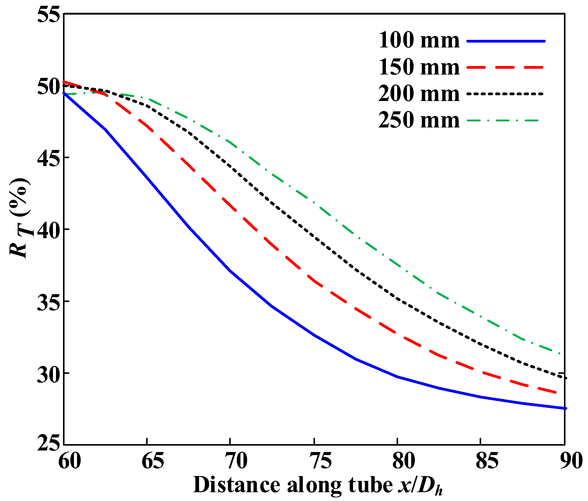
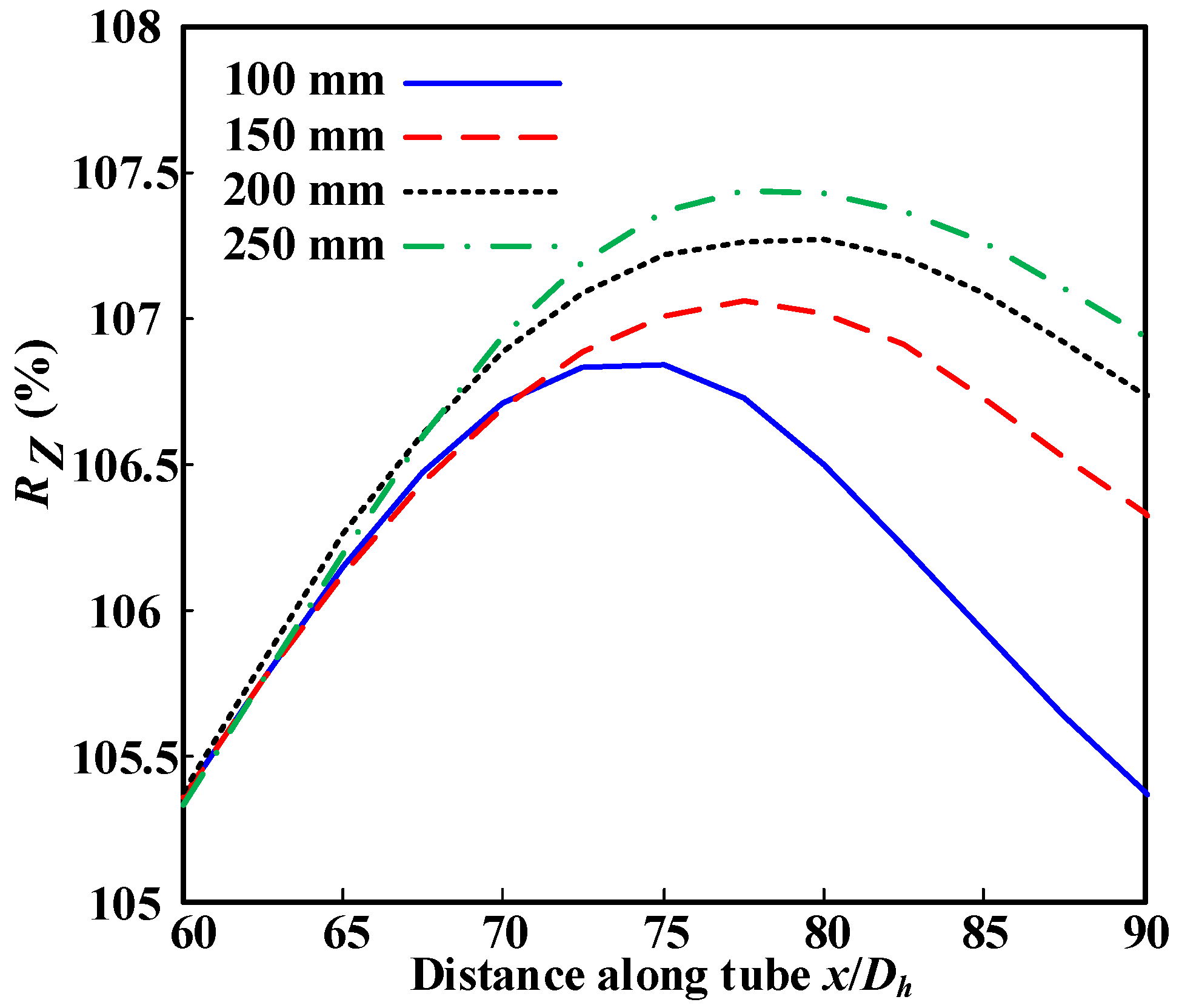
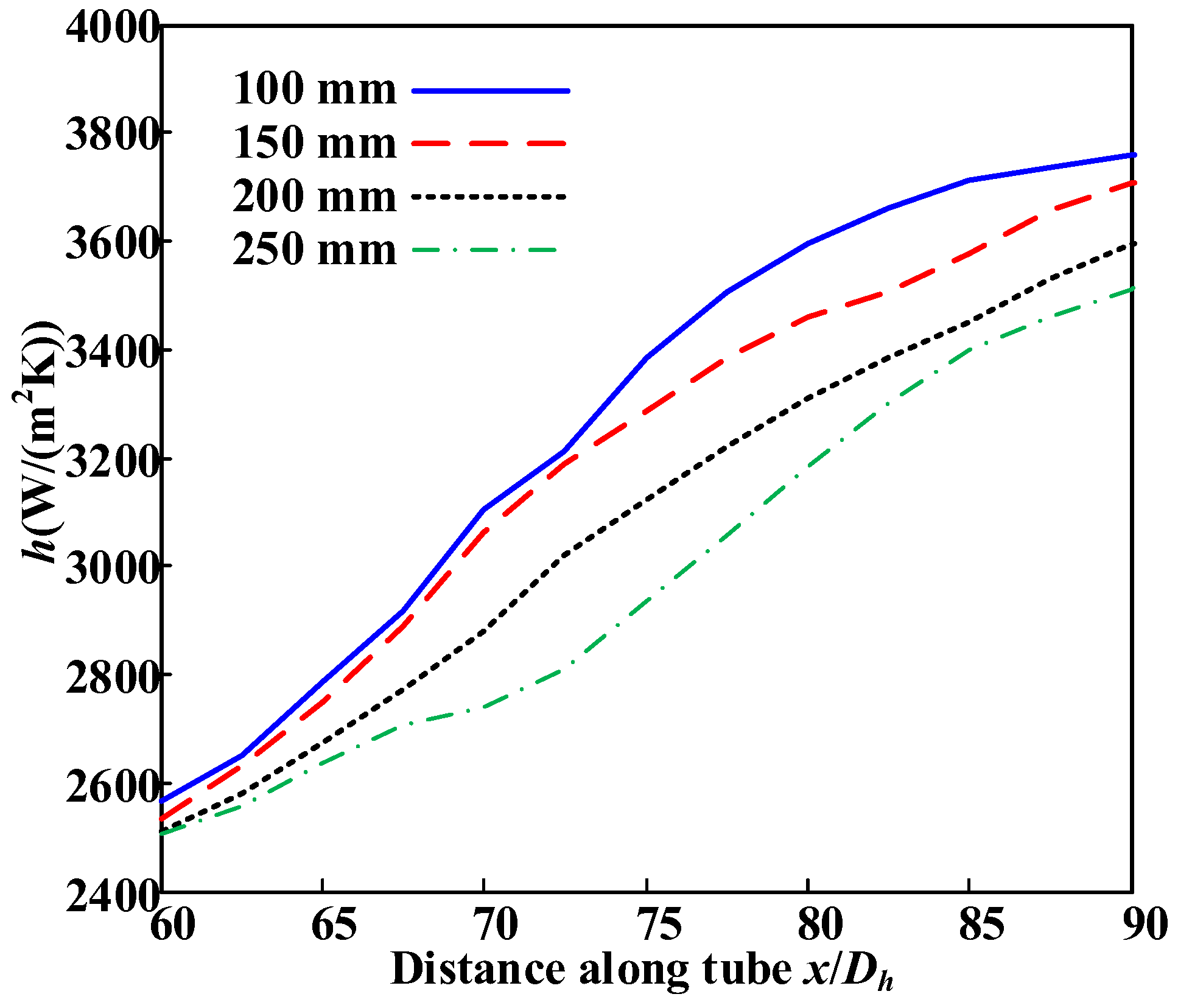
4.3. Radius of Curvature Effect on Heat and Mass Transfers in the Curved Cooling Channel

In the curved channel, the centrifugal force and secondary flow velocity were inversely proportional to the radii of the curvature. In this section, the supercritical hydrocarbon fuel flow field for various radii of curvature, R, is numerically investigated to study the secondary flow effect on the heat and mass transfers of hydrocarbon fuels.
The four radii of curvature were 100 mm, 150 mm, 200 mm, and 250 mm, respectively. The total length of the curved cooling channel was 450 mm. The geometric dimensions of the curved channels are shown in Table 2. Parts I, II, and IV are straight channels, and Part III is a 1-rad bending section. The parameters in the numerical simulations are the same as those of case 1.
Since the radius of curvature is inversely proportional to the centrifugal force, the smaller the radius of curvature, the greater the secondary flow velocity, as shown in Figure 15. Therefore, with the decreasing radius of curvature, the heat and components exchange between the near-wall region and the main flow is much more severe (shown in Figure 16). The non-uniformity coefficients of fuel temperature and conversion decrease along the mass flow direction, as shown in Figure 17 and Figure 18. Thus, with the decreasing radius of curvature, the fuel heat-absorbing capacity rises, and the heat transfer coefficient increases, as shown in Figure 19. When the radius of curvature changed from 100 mm to 200 mm, the heat transfer coefficient at x/Dh = 90 decreased by 7.2%. The increasing radius of curvature deteriorated the heat and mass transfers and inhibited the utilization level of fuel heat sink in the curved cooling channel.

5. Conclusions

In this paper, the flow and heat transfer characteristics of China RP-3 aviation kerosene in the curved rectangular regenerative cooling channel were numerically studied. A detailed pyrolytic chemical reaction mechanism was adopted to describe the hydrocarbon fuel pyrolysis. The secondary flow effect on fluid flows and heat transfer was studied by comparing the distribution of the fuel conversion and heat transfer coefficient in both a curved cooling channel and a straight cooling channel. In addition, the fluid flows and heat transfer in the curved cooling channel at different inlet mass flow rates and radii of the curvature were also investigated. The main results are summarized as follows:
(1)
The secondary flow enhanced the fluid mixing and thermal exchange in the curved cooling channel. Additionally, the fuel conversion and heat-absorbing capacity was higher, and the heat transfer was effectively enhanced. At the outlet of the curved section, the heat transfer coefficient increased by around 90%.
(2)
With the increase of inlet mass flow rate, the centrifugal force became larger. The heat and components exchange between the near-wall region and the main flow was much more severe. The non-uniformities of the fuel temperature and conversion at the cross section decreased, which was beneficial for the promotion of fuel pyrolysis, and helpful for improving the utilization level of the fuel heat-absorbing capacity. The increasing inlet mass flow rate can effectively enhance the heat transfer in a curved cooling channel.
(3)
The radius of curvature was inversely proportional to the centrifugal force, so as the radius of curvature decreased, the secondary flow velocity increased. Therefore, the increasing radius of curvature raised non-uniformities of the fuel temperature and conversion at the cross section, which suppresses the fuel pyrolysis and reduces the utilized efficiency of the fuel heat-absorbing capacity. The increasing radius of curvature deteriorated the heat transfer in the curved cooling channel.

Author Contributions

Conceptualization, Y.C. and K.G.; methodology, K.G.; software, S.L.; validation, Y.Z., L.W. and Z.C.; formal analysis, S.L.; investigation, K.G.; resources, Y.C.; writing—original draft preparation, Y.Z.; writing—review and editing, K.G.; visualization, L.W.; supervision, Y.C.; project administration, S.L.; funding acquisition, Y.C. All authors have read and agreed to the published version of the manuscript.

Funding

This research was funded by the National Natural Science Foundation of China (Grant No. 51976046, 51806048 and 51776175), the National Key Laboratory of Science and Technology (Grant No. 6142701190106), Key Basic Research Projects of the Foundation Strengthening Program (Grant No. 2019-JCJQ-ZD-083-05), the Shenzhen Technology Project (Grant Nos. ZDSYS201707280904031, GXWD20201230155427003-20200823111310002, and JCYJ20180306171941256), and the Open Cooperative Innovation Fund of Xi’an Institute of Modern Chemistry (Grant No. SYJJ200313).

Institutional Review Board Statement

Not applicable.

Informed Consent Statement

Not applicable.

Data Availability Statement

All data can be accessed from the corresponding author upon request.

Conflicts of Interest

The authors declare no conflict of interest.

Nomenclature

Asurface area, m2U, uvelocity, m/s
a, bparameters in PR EosVvolume, m3
Cpspecific heat capacity, J/kg/Kvdiffusion volume, m3
Ddiffusion coefficient, m2/sVSecsecondary flow velocity, m/s
Dhhydraulic diameter, mmx, y, zthree coordinate directions of Cartesian coordinate system
hheat transfer coefficient, W/(m2·K)ximole fraction of species i
HEnthalpy, J/KgYmass fraction
M
Mij
mass flow rate, g/s
the mixed molar mass of species i and species j, kg/(K·mol)
ZRP-3conversion of RP-3
NuNusselt numberGreek
ppressure, MPaρdensity, kg/m3
PrPrandtl numberτviscous stress, N/m2
prcomparison pressureλthermal conductivity, W/(m·K)
q heat flux, W/m2Subscripts
Rcurvature radius, mm, or molar gas constant, J/(K·mol), or non-uniformityeffeffective parameter
ReReynolds numberwwall parameter
SMsource term of chemical reactionbbulk fluid parameter
TTemperature, Kininlet parameter
TbBulk fluid temperatureispecies
Twwall temperaturemmixture
Trcomparison temperature+value under low pressure

References

  1. Zhu, Y.; Peng, W.; Xu, R.; Jiang, P. Review on active thermal protection and its heat transfer for airbreathing hypersonic vehicles. Chin. J. Aeronaut. 2018, 31, 1929–1953. [Google Scholar] [CrossRef]
  2. Wang, H.; Wang, Z.; Sun, M.; Wu, H. Combustion modes of hydrogen jet combustion in a cavity-based supersonic combustor. Int. J. Hydrogen Energy 2013, 38, 12078–12089. [Google Scholar] [CrossRef]
  3. Lv, L.; Wen, J.; Fu, Y.; Quan, Y.; Zhu, J.; Xu, G. Numerical investigation on convective heat transfer of supercritical aviation kerosene in a horizontal tube under hyper gravity conditions. Aerosp. Sci. Technol. 2020, 105, 105962. [Google Scholar] [CrossRef]
  4. Wang, H.; Wang, Z.; Sun, M.; Qin, N. Large-Eddy/Reynolds-averaged Navier–Stokes simulation of combustion oscillations in a cavity-based supersonic combustor. Int. J. Hydrogen Energy 2013, 38, 5918–5927. [Google Scholar] [CrossRef]
  5. Hou, L.-Y.; Zhang, D.-R.; Zhang, X.-X. Interaction between thermal cracking and steam reforming reactions of aviation kerosene. Fuel Process. Technol. 2017, 167, 655–662. [Google Scholar] [CrossRef]
  6. Xu, Q.; Lin, G.; Li, H. Evaluation Model for Fast Convective Heat Transfer Characteristics of Thermal Cracked Hydrocarbon Fuel Regenerative Cooling Channel in Hydrocarbon-Fueled Scramjet. Appl. Therm. Eng. 2021, 199, 117616. [Google Scholar] [CrossRef]
  7. Sun, X.; Meng, H.; Zheng, Y. Asymmetric heating and buoyancy effects on heat transfer of hydrocarbon fuel in a horizontal square channel at supercritical pressures. Aerosp. Sci. Technol. 2019, 93, 105358. [Google Scholar] [CrossRef]
  8. Taddeo, L.; Gascoin, N.; Chetehouna, K.; Ingenito, A.; Stella, F.; Bouchez, M.; Le Naour, B. Experimental Study of Pyrolysis-Combustion Coupling in a Regeneratively Cooled Combustor: System Dynamics Analysis. Aerosp. Sci. Technol. 2017, 67, 473–483. [Google Scholar] [CrossRef]
  9. Hou, L.-Y.; Dong, N.; Sun, D.-P. Heat transfer and thermal cracking behavior of hydrocarbon fuel. Fuel 2013, 103, 1132–1137. [Google Scholar] [CrossRef]
  10. Xu, K.; Sun, X.; Meng, H. Conjugate heat transfer, endothermic fuel pyrolysis and surface coking of aviation kerosene in ribbed tube at supercritical pressure. Int. J. Therm. Sci. 2018, 132, 209–218. [Google Scholar] [CrossRef]
  11. Zhao, G.; Song, W.; Zhang, R. Effect of pressure on thermal cracking of china RP-3 aviation kerosene under supercritical conditions. Int. J. Heat Mass Transf. 2015, 84, 625–632. [Google Scholar] [CrossRef]
  12. Ward, T.; Ervin, J.S.; Zabarnick, S.; Shafer, L. Pressure Effects on Flowing Mildly-Cracked n-Decane. J. Propuls. Power 2005, 21, 344–355. [Google Scholar] [CrossRef]
  13. Feng, Y.; Jiang, Y.; Li, X.; Zhang, S.; Qin, J.; Cao, Y.; Huang, H. Numerical study on the influences of heat and mass transfers on the pyrolysis of hydrocarbon fuel in mini-channel. Appl. Therm. Eng. 2017, 119, 650–658. [Google Scholar] [CrossRef]
  14. Feng, Y.; Liu, S.; Qin, J.; Cao, Y.; Jiang, Y.; Zhang, S. Numerical study on the influence of turbulence on the pyrolysis of hydrocarbon fuel in mini-channel. Int. J. Heat Mass Transf. 2018, 119, 768–776. [Google Scholar] [CrossRef]
  15. Liu, Z.; Liang, J.; Pan, Y. Numerical study of coupled heat transfer of supercritical n-decane in a curved cooling channel. J. Thermophys. Heat Transf. 2016, 30, 635–641. [Google Scholar] [CrossRef]
  16. Matsubara, K.; Matsui, A.; Miura, T.; Sakurai, A.; Suto, H.; Kawai, K. A spatially advancing turbulent flow and heat transfer in a curved channel. Heat Transf. Asian Res. 2010, 39, 14–26. [Google Scholar] [CrossRef]
  17. Amp, K.M.; Takeda, M. Heat Transfer Characteristics and Reynolds Stress Budget of Spatially Advancing Turbulent Flow in a Curved Channel. Numer. Heat Transf. 2011, 60, 234–253. [Google Scholar]
  18. Pizzarelli, M.; Nasuti, F.; Onofri, M. Investigation of transcritical methane flow and heat transfer in curved cooling channels. In Proceedings of the 45th AIAA/ASME/SAE/ASEE Joint Propulsion Conference & Exhibit, Denver, CO, USA, 2–5 August 2009. [Google Scholar] [CrossRef]
  19. Pizzarelli, M.; Nasuti, F.; Onofri, M. Analysis of Curved-Cooling-Channel Flow and Heat Transfer in Rocket Engines. J. Propuls. Power 2011, 27, 1045–1053. [Google Scholar] [CrossRef]
  20. Pizzarelli, M. Effectiveness of Spalart–Allmaras Turbulence Model in Analysis of Curved Cooling Channels. AIAA J. 2013, 51, 2158–2167. [Google Scholar] [CrossRef]
  21. Mondal, R.N.; Watanabe, T.; Hossain, M.A.; Yanase, S. Vortex-Structure and Unsteady Solutions with Convective Heat Transfer Through a Curved Duct. J. Thermophys. Heat Transf. Asian Res. 2017, 31, 243–254. [Google Scholar] [CrossRef]
  22. Röhrig, R.; Jakirlić, S.; Tropea, C. Comparative computational study of turbulent flow in a 90° pipe elbow. Int. J. Heat Fluid Flow 2015, 55, 120–131. [Google Scholar] [CrossRef]
  23. Jing, T.; He, G.; Li, W.; Zhang, D.; Qin, F.; Li, R. Flow and thermal analyses of supercritical hydrocarbon fuel in curved regenerative cooling channel around cavity in rocket based combined cycle engine. Appl. Therm. Eng. 2018, 145, 423–434. [Google Scholar] [CrossRef]
  24. Sun, X.; Xu, K.; Meng, H. Supercritical-Pressure Heat Transfer, Pyrolytic Reactions and Surface Coking of n-Decane in Helical Tubes. Energy Fuels 2018, 32, 12298–12307. [Google Scholar] [CrossRef]
  25. Ward, T.; Ervin, J.S.; Striebich, R.C.; Zabarnick, S. Simulations of Flowing Mildly-Cracked Normal Alkanes Incorporating Proportional Product Distributions. J. Propuls. Power 2004, 20, 394–402. [Google Scholar] [CrossRef]
  26. Jing, T.; He, G.; Lin, B.B.; Li, W.; Qin, F.; Liu, Y. Thermal analysis of RBCC engine at ejector, ramjet and scramjet modes. In Proceedings of the 14th International Energy Conversion Engineering Conference, Salt Lake City, UT, USA, 25–27 July 2016. [Google Scholar]
  27. Gong, K.; Cao, Y.; Feng, Y.; Liu, S.; Qin, J. Influence of secondary reactions on heat transfer process during pyrolysis of hydrocarbon fuel under supercritical conditions. Appl. Therm. Eng. 2019, 159, 113912. [Google Scholar] [CrossRef]
  28. Jiang, R.; Liu, G.; Zhang, X. Thermal Cracking of Hydrocarbon Aviation Fuels in Regenerative Cooling Microchannels. Energy Fuels 2013, 27, 2563–2577. [Google Scholar] [CrossRef]
  29. Huang, W.; Li, S.-B.; Yan, L.; Wang, Z.-G. Performance evaluation and parametric analysis on cantilevered ramp injector in supersonic flows. Acta Astronaut. 2013, 84, 141–152. [Google Scholar] [CrossRef]
  30. Zhang, S.; Feng, Y.; Zhang, D.; Jiang, Y.; Qin, J.; Bao, W. Parametric numerical analysis of regenerative cooling in hydrogen fueled scramjet engines. Int. J. Hydrogen Energy 2016, 41, 10942–10960. [Google Scholar] [CrossRef]
  31. Cismondi, M.; Mollerup, J. Development and application of a three-parameter RK–PR equation of state. Fluid Phase Equilibria 2005, 232, 74–89. [Google Scholar] [CrossRef]
  32. Kim, S.-K.; Choi, H.-S.; Kim, Y. Thermodynamic modeling based on a generalized cubic equation of state for kerosene/LOx rocket combustion. Combust. Flame 2012, 159, 1351–1365. [Google Scholar] [CrossRef]
  33. Poling, B.E.; Prausnitz, J.M.; O’Connell, J.P. The Properties of Gases and Liquids; McGraw-Hill: New York, NY, USA, 2000. [Google Scholar]
  34. Liu, S.; Feng, Y.; Chu, Y.; Gong, K.; Cao, Y. Numerical study of catalytic steam reforming of aviation kerosene at supercritical pressures. Fuel 2018, 212, 375–386. [Google Scholar] [CrossRef]
  35. Meyer, M.L. The Effect of Cooling Passage Aspect Ratio on Curvature Heat Transfer Enhancement; NASA TM-107426; NASA: Washington, DC, USA, 1997.
  36. Meyer, M. Electrically heated tube investigation of cooling channel geometry effects. In Proceedings of the 31st Joint Propulsion Conference and Exhibit, San Diego, CA, USA, 10–12 July 1995; pp. 10–12. [Google Scholar] [CrossRef] [Green Version]
  37. Lin, B.; Pan, H.; Shi, L.; Ye, J. Effect of Primary Rocket Jet on Thermodynamic Cycle of RBCC in Ejector Mode. Int. J. Turbo Jet-Engines 2020, 37, 61–70. [Google Scholar] [CrossRef] [Green Version]
  38. Xu, K.; Tang, L.; Meng, H. Numerical study of supercritical-pressure fluid flows and heat transfer of methane in ribbed cooling tubes. Int. J. Heat Mass Transf. 2015, 84, 346–358. [Google Scholar] [CrossRef]
  39. Gong, K.; Cao, Y.; Feng, Y.; Zhang, Y.; Qin, J. Flow and Mass Transfer of Pyrolytic Aviation Kerosene in Curved Channel. J. Thermophys. Heat Transf. 2021, 35, 53–62. [Google Scholar] [CrossRef]
  40. Berger, S. Flow and heat transfer in curved pipes and tubes. In Proceedings of the 29th Aerospace Sciences Meeting, Reno, NV, USA, 7–10 January 1991. [Google Scholar] [CrossRef]
  41. Zhang, S.; Feng, Y.; Jiang, Y.; Qin, J.; Bao, W.; Han, J.; Haidn, O.J. Thermal behavior in the cracking reaction zone of scramjet cooling channels at different channel aspect ratios. Acta Astronaut. 2016, 127, 41–56. [Google Scholar] [CrossRef]
Figure 1. Validation of heat transfer in curved channel.
Applsci 12 02356 g001
Figure 2. The flow-path configuration of engine [37].
Applsci 12 02356 g002
Figure 3. Schematic and dimensions of simulation model: (a) cross section of channel (b) schematic of channel along axial direction.
Applsci 12 02356 g003
Figure 4. Temperature distribution at different cross sections: (a) curved channel and (b) straight channel.
Applsci 12 02356 g004
Figure 5. Fuel temperature in the centerline along y axis at different cross sections.
Applsci 12 02356 g005
Figure 6. Mass fraction of RP-3 distribution at different cross sections: (a) curved channel and (b) straight channel.
Applsci 12 02356 g006
Figure 7. Conversion of RP-3 in the centerline along y axis at different cross sections.
Applsci 12 02356 g007
Figure 8. Secondary flow distribution and streamline at different cross sections: (a) secondary flow and (b) streamline.
Applsci 12 02356 g008
Figure 9. Variation of conversion of RP-3 along the flow direction.
Applsci 12 02356 g009
Figure 10. Variation of heat transfer coefficient along the flow direction.
Applsci 12 02356 g010
Figure 11. Secondary flow velocity with different mass flow rates along the flow direction.
Applsci 12 02356 g011
Figure 12. Distribution of RT with different mass flow rates along the flow direction.
Applsci 12 02356 g012
Figure 13. Distribution of RZ with different mass flow rates along the flow direction.
Applsci 12 02356 g013
Figure 14. Heat transfer coefficient with different mass flow rates along the flow direction.
Applsci 12 02356 g014
Figure 15. Secondary flow velocity with different radii of curvature along the flow direction.
Applsci 12 02356 g015
Figure 16. Distributions of flow field at the cross section of x/Dh = 75 with different radii of curvature: (a) Temperature and (b) mass fraction of RP-3.
Applsci 12 02356 g016
Figure 17. Distribution of RT with different radii of curvature along the flow direction.
Applsci 12 02356 g017
Figure 18. Distribution of RZ with different radii of curvature along the flow direction.
Applsci 12 02356 g018
Figure 19. Heat transfer coefficient with different radii of curvature radius along the flow direction.
Applsci 12 02356 g019
Table 1. Boundary conditions in different mass flow rate cases.
Casem (g/s)Tin (K)Pin (MPa)Reinq″ (W/m2)
11.34170036.0 × 1045.0 × 106
21.78870038.0 × 1046.67 × 106
32.23570031.0 × 1058.33 × 106
Table 2. Geometric parameters in simulations with different radii of curvature.
CaseR
(mm)
Part I
(mm)
Part II
(mm)
Part III
(mm)
Part IV
(mm)
41005050100250
51505050150200
62005050200150
72505050250100
Publisher’s Note: MDPI stays neutral with regard to jurisdictional claims in published maps and institutional affiliations.

