Abstract
The characteristics of transmitted acoustic field have important significance to the leakage detection and the acoustic metasurface technology. When the additional leak holes are present, the conventional single neck Helmholtz resonator will naturally become the one with multiple necks. Based on such a background, in this paper, the effects of leakages on the transmission properties of a Duct Helmholtz Resonator (DHR) device is investigated both analytically and numerically. A set of closed-form formulas are derived to analytically predict the transmission spectra of the DHR device with leakages. The theoretical results are compared with COMSOL predictions. The simulation results show that the number and width of leak holes have significant influences on the amplitude, phase shift of the transmitted wave, and resonance frequency of the DHR system.
1. Introduction
Duct-Helmholtz-Resonator (DHR) structure, which consists of a resonance cavity connecting with the main duct through a neck, has wide applications in engineering. Depending on the designed structural parameters and the operating frequency band, it can realize different functions.
DHR device with one resonance peak have been widely used for sound absorption. Since the single resonator has a narrow resonance peak, combining several resonators with different resonant frequencies is a popular way to obtain a broader band of noise attenuation [1,2,3]. In recent years, DHR has often been used as a wavefront-shaping device in metasurface structure to manipulate the transmitted wave. By introducing the discrete phase variations from 0 to 2π across the DHR-based metasurface, full control of the phase of the transmitted acoustic field can be achieved [4,5,6,7]. By using the DHR-based metasurface with transversal gradient phase, various unique phenomena or properties have been revealed, such as anomalous refraction/reflection [8], acoustic focusing [9], zero/negative refraction [10], and sound cloaking [11], etc. Besides, metamaterials with negative mass or negative modulus of elasticity can also be achieved by DHR elements [12,13,14].
Most of the DHR-based studies that adopted the assumption of perfect duct and cavity shells had no leakage considered. However, there may be unwanted leakages in the DHR device for different reasons, such as incomplete welding in shells, the corrosion of pipe walls [15], aging of the pipes [16], and so on. Although leakages may greatly affect the acoustic performance of the structures, limited research has been presented regarding this subject. Selamet et al. (2009) designed a Helmholtz resonator prototype with varying levels of intentional leakage due to holes in the baffle [17]. The results showed that the leak holes are found to have a significant impact on transmission loss. Lee et al. (2013) investigated the effect of leakage on the acoustic performance of reactive silencers, such as expansion chambers, Helmholtz resonators, and quarter-wave resonators, through theoretical analysis and experiment [18]. They found that the impact of the leakage on the cavity is significant near the resonance, and the transmission loss is almost independent of the locations of the leakage.
When the leakages are present, the cavity will have one or more additional channels (leak holes) to communicate with the main duct. In this case, the original Helmholtz resonator naturally becomes the one with multiple necks. Up to now, only a few results have been reported on the acoustic characteristics of the multi-neck Helmholtz resonator. Langfeldt et al. (2019) developed an analytical model to calculate the resonance frequency and the input impedance of a Helmholtz resonator with multiple necks [19]. The results show that small additional holes in the Helmholtz resonator have significant influences on the resonance frequency and the absorption performance. Zhao et al. (2019) designed a dual-tube Helmholtz resonator-based triboelectric nanogenerator (TENG) for efficient harvesting of acoustic energy [20]. Based on the coupling mechanisms of TENG and acoustic propagation, they provided a theoretical guideline for improving energy output and broadening the frequency band. These limited studies provide a basis for understanding the effect of multiple necks on the acoustic characteristics of Helmholtz resonators.
Since the transmitted wave carries physical information of the leakage, the acoustic transmission properties of the DHR device with multiple necks are of great significance for the leakage detection and localization of gas pipeline system or metasurface structures [21,22,23]. To examine the effects of leakages on the acoustic performance of the DHR device, in this paper, a set of explicit formulas were derived. The effects of the number and the size of leak holes, and the distance between the leak hole and the main neck on the transmission properties of DHR were predicted. Compared with the COMSOL finite element (FE) simulations, the developed theoretical formulas can be employed to better understand and quickly estimate the impact of leakage on the transmission properties of the DHR device, and thus have significant meaning in the field of oil and gas pipelines, as well as acoustic metasurface engineering.
2. Acoustic Transmission of the DHR Device
2.1. Impedance Formulas
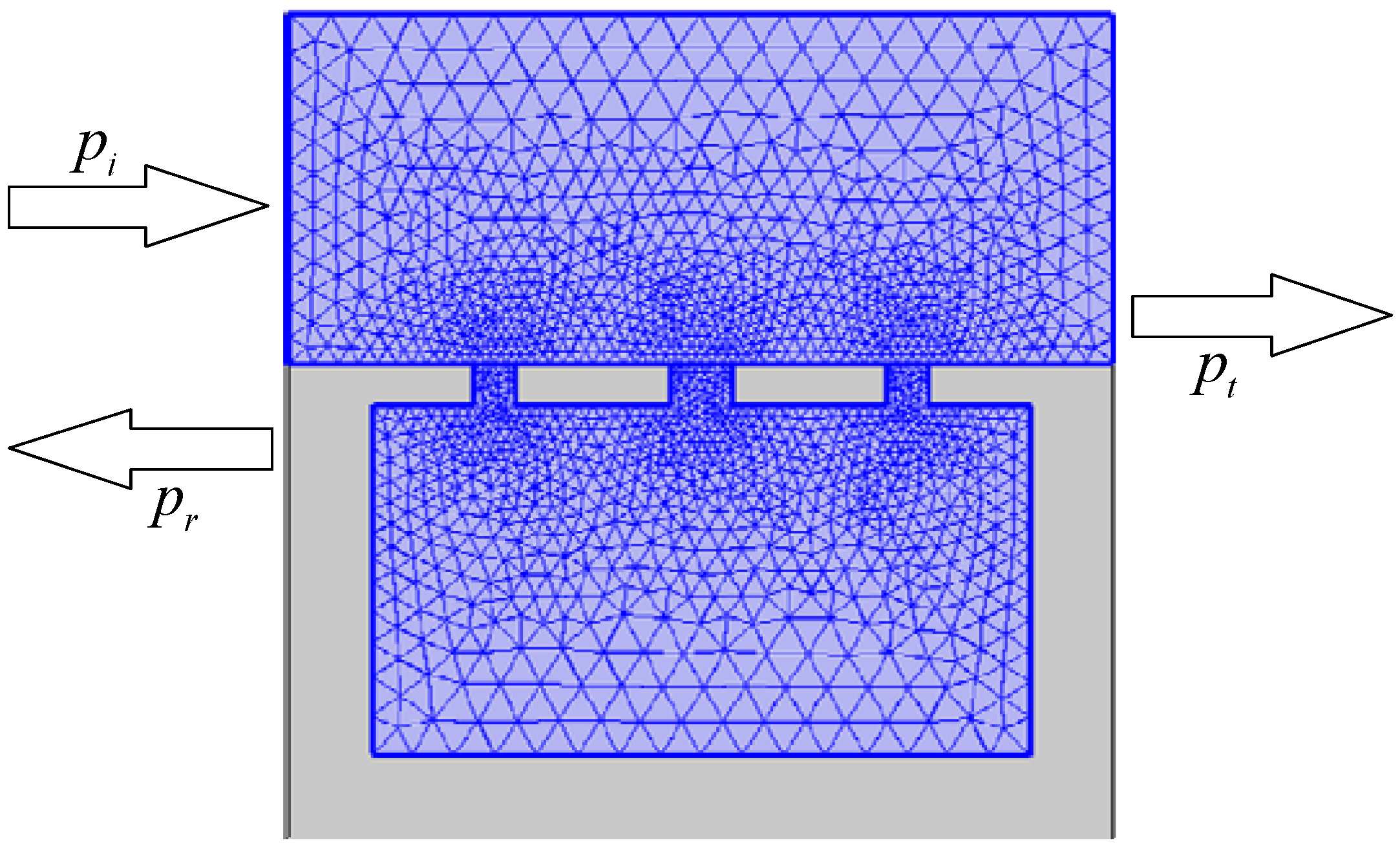
As stated in Section 1, the investigation of the leakage effect of a single neck Helmholtz resonator can be attributed to the prediction of the transmission spectrum of a corresponding multi-neck resonator. A DHR device, that is a duct loaded by a Helmholtz resonator with necks, is shown Figure 1. Of all the necks, we assumed that one was the main neck and the rest were the leak holes. In Figure 1, the height of the duct was . The total length and height of the resonator were and , respectively. The height of each neck was and the width of the necks were , ,…, , respectively. The height and the length of the cavity are and , respectively. The distance between the inlet of DHR to the midpoint of the first neck was , the distance between the midpoints of the neck and the neck was , and the distance between the outlet of DHR to the midpoint of the neck was . , , and were acoustic pressure of incident, reflected and transmitted waves, respectively.
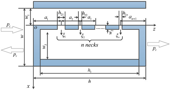
Figure 1.
Schematic diagram of a DHR system.
If we assume that the size of DHR is much smaller than the wavelength of the acoustic wave, then the air in the neck and the cavity can be treated as the lumped mechanical elements. In this way, the governing equations of the Helmholtz resonator with necks can be written as
where, is the mass of the air in the neck, is the equivalent spring stiffness of the cavity, and is the average acoustic pressure acting on the neck. and are the displacement and the acceleration of the air column in the neck, respectively.
Based on the analogy of electro-mechanics-acoustics, the acoustic mass of the neck , and the acoustic capacity of the cavity can be written as
Under the assumption of simple harmonic motion, the volume velocity of the air column in the neck can be expressed as
where, is the imaginary unit, is the angular frequency of the acoustic wave.
Substitution of Equations (2) and (3) in Equation (1) yields the following acoustic relation between the neck and the cavity
It will be seen from the end of this subsection that the relation described by Equation (4) is not accurate enough. Therefore, in what follows, a set of more accurate analytical formulas that reflect the acoustic characteristics of the system will be derived.
The acoustic impedance of the neck is
The acoustic pressure in the cavity can be expanded in terms of normal modes [24], given by
where
is the normal mode, and satisfies the following orthogonal condition
where is Kronecker delta, and is the cross-sectional area of the cavity. and are the modal amplitudes corresponding to the components traveling in the positive and negative directions, respectively. and are the wave number components in the and directions, respectively. They can be expressed as
where is the wave number, , is the sound speed.
Only the plane wave component is considered. In this case, substitute into Equation (9), the wave number components in the and directions can be written as and , respectively. From Equation (8), we have and . Now, Equation (6) can be recast as
For the time-harmonic wave, the velocity and the acoustic pressure are related by
where is the air density, and is the characteristic impedance of the air.
Substituting Equation (10) into Equation (11), the particle velocity can be obtained as
Considering rigid wall boundary condition at , we have
The average velocity of the air column in the neck at can be written as
where is the volume velocity of the air column in the neck.
At , the velocity distribution given by Equation (12) should be equal to that generated by the motions of the air columns in the necks. Therefore, substituting Equation (14) into Equation (12), and integrating along the
direction, we obtain
where is the coordinate of the midpoint of the neck, and is the coordinate of the midpoint of the cavity.
According to Equation (15), the second relation between and is of the form
Based on Equations (13) and (16), we can solve and , given by
The average acoustic pressure field at the junction of the neck and cavity can be defined as
After substituting Equation (17) into Equation (10), the average acoustic pressure field at can be obtained from Equation (18), given by
After obtaining the relation between and at , the acoustic impedance of the cavity corresponding to the neck can be written as
According to the impedance transfer formula, the effective acoustic impedance at the midpoint of the duct can be expressed as
where is the corrected height of the neck [25] and is the correction coefficient, which is dependent on the geometric parameters of the neck.
Substituting Equation (20) into Equation (21), we obtain
In order to predict the transmission coefficient more accurately, the radiation impedance due to vibration of the air column in the neck should be considered. In fact, the neck plays the role of acoustic capacity as well as acoustic mass. The imaginary part of the radiation impedance of the neck [24] can be written as
The overall acoustic impedance at the intersection between the duct and the neck is the superposition of the transfer impedance at the midpoint of the duct and the imaginary part of the radiation impedance, given by
Since the size of the neck is much smaller than the cavity, Equation (24) can be approximated as
For , we have , , and . Multiplying both sides of Equation (25) by , we can obtain
Note that Equation (26) is the same as Equation (4), if we define
Obviously, acoustic relation given by Equation (4) is a simplified version of Equation (25). In order to improve the prediction accuracy of transmittance, in what follows, the acoustic impedance given by Equation (25) is adopted.
2.2. Acoustic Transfer Relations in the Duct
Acoustic pressure and volume velocity at the junction between the neck and the duct satisfy the following equation
Substituting Equation (25) into Equation (28), we have
Equation (29) can be simplified as
where
Writing Equation (30) into the matrix form, we obtain
where is a matrix of order , given by
Let , Equation (32) can be reduced to
where
Now, consider the case that the incident acoustic wave enters the duct at the entrance . Let and denote the incident acoustic pressure and volume velocity, respectively. Similarly, let and denote the acoustic pressure and volume velocity at the exit , respectively.
For , acoustic pressure and volume velocity can be expressed as
where and are, respectively, the transfer coefficients of the acoustic wave along the and direction. is the acoustic impedance of the duct, given by
For , acoustic pressure and volume velocity can be written as
Similarly, for , we have
The continuity conditions of acoustic pressure and volume velocity at are
Substituting Equation (36) into Equation (40), we obtain
where
Similarly, at the exit , we have
Substituting Equation (39) into Equation (43), we obtain
where
At the midpoint of the first neck , we have the following relation
Similarly, at the midpoint of the neck , the following conditions hold true
Based on Equations (35), (36), (38), (39), (46) and (47), the equations can be obtained, from which the transfer matrix from the first neck to the neck can be solved, see Appendix A.
Finally, we obtain the transfer relation between the transmitted and the incident state parameters, given by
in which, the total transfer matrix is the form
2.3. Reflection and Transmission Coefficients
The reflected and transmitted waves can be expressed as [26]
where and are the reflected and transmitted acoustic pressure, respectively. and are the reflection and transmission coefficients of the plane wave in modes. and are the wave number components in the vertical and horizontal directions, which satisfy and , where, is the incidence angle of the acoustic wave.
In this paper, we take and . In this case, we have and . Now, Equation (50) can be reduced to
At , by the continuity of velocity, we can get
where , , and are acoustic velocities of incident wave, reflected wave and wave in the duct, respectively.
Considering Equations (51) and (11), and the momentum conservation law, Equation (52) can be reduced to
Integrating Equation (53) along direction, we obtain
According to Equation (54), the reflection coefficient can be solved as follows
where .
At , the transmission coefficient can be derived as
Substituting Equation (55) into Equation (51), the average acoustic pressure at can be written as
In a similar way, the average acoustic pressure at can be written as
Using Equations (48), (57) and (58) we can obtain and as
where represents the corresponding element in the matrix .
Substituting Equation (59) into Equations (55) and (56), the reflection and transmission coefficients are written as
The modulus and the argument of complex number represent amplitude and phase shift of the transmission coefficient, respectively.
3. Results and Discussions
In this section, the developed theoretical formulas are verified by commercial FE package COMSOL Multiphysics 5.2. The effects of leakage on the transmission properties of DHR device are investigated theoretically and numerically.
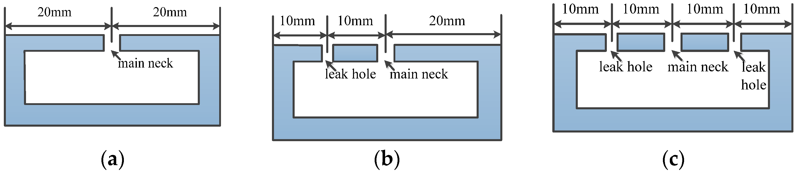
The baseline parameters of DHR device in simulations are as follows. Referring to Figure 1, the total length and the height of DHR are taken as and , respectively. The height of the duct is . The height of each neck is and the widths of the main neck and the leak hole are and , respectively. The height and the length of the cavity are and , respectively. In the case of no leak hole, the distance from the inlet or the outlet to the main neck is . For the case of one leak hole, the position of the main neck is unchanged, and the distance between the leak hole and the main neck is . For the case of two leak holes, the location of the main neck is unchanged, while the two leak holes are placed on both sides of the main neck with a distance of . The positions of the main neck and the leak holes are shown in Figure 2. The amplitude and the frequency range of the incident acoustic wave are and , respectively.
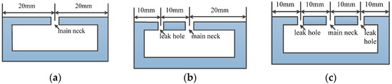
Figure 2.
The locations of the main neck and the leak holes used in simulations; (a) No leak hole; (b) One leak hole; (c) Two leak holes.
The transmittance predictions are performed to capture the influences of leakage by using the developed theoretical formulas. The results are compared with those obtained by COMSOL software. In COMSOL simulations, the pressure acoustic module is used, and the acoustic FEM mesh is shown in Figure 3. All the walls are taken as hard boundaries, and the periodic boundary condition is applied in the direction perpendicular to the incident wave.
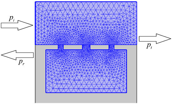
Figure 3.
COMSOL acoustic finite element model (FEM) of the DHR device with two leak holes.
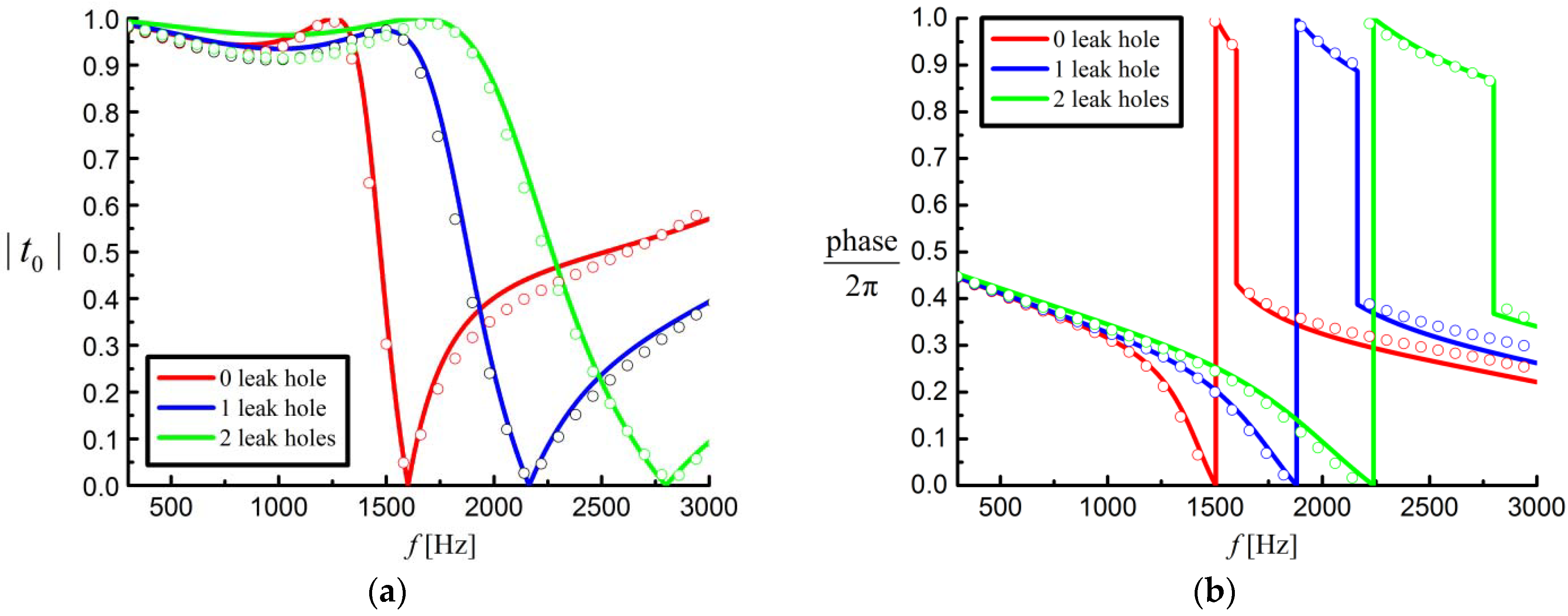
As shown in Figure 4, the theoretical results (solid lines) from Equation (60) are in very good agreement with the COMSOL predictions (circle lines), which confirms the good accuracy of the theoretical formulas. In Figure 4, the frequency corresponding to the point with zero transmittance represents the resonance frequency of the DHR system, which is the key parameter in the design of the acoustic absorbers. Since all the holes share one cavity, the DHR device exhibits only one non-zero resonance frequency, at which the transmission phase undergoes an abrupt jumping. From the perspective of sound absorption, when the frequency of transmitted wave approaches the resonance point, nearly perfect reflection appears with a significant decrease of transmittance. It can be seen from Figure 4 that the resonance frequency of the system increases with the number of leak holes. This means that additional leak holes in the Helmholtz resonator always leads to an increase of resonance frequency of the system. Obviously, the change of the resonance frequency can be used as an important criterion for acoustic leak detection. In Figure 4, the region below the resonance frequency is called the high transmission band, which is usually utilized to control the transmitted wavefront of the acoustic metamaterials, so that anomalous refraction, acoustic focusing, and other functions can be realized.
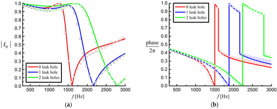
Figure 4.
Effects of the number of leak holes on the transmission properties of the DHR device. The solid lines represent the theoretical results, while the circle lines represent the COMSOL predictions. (a) Amplitude vs. frequency; (b) Phase shift vs. frequency.
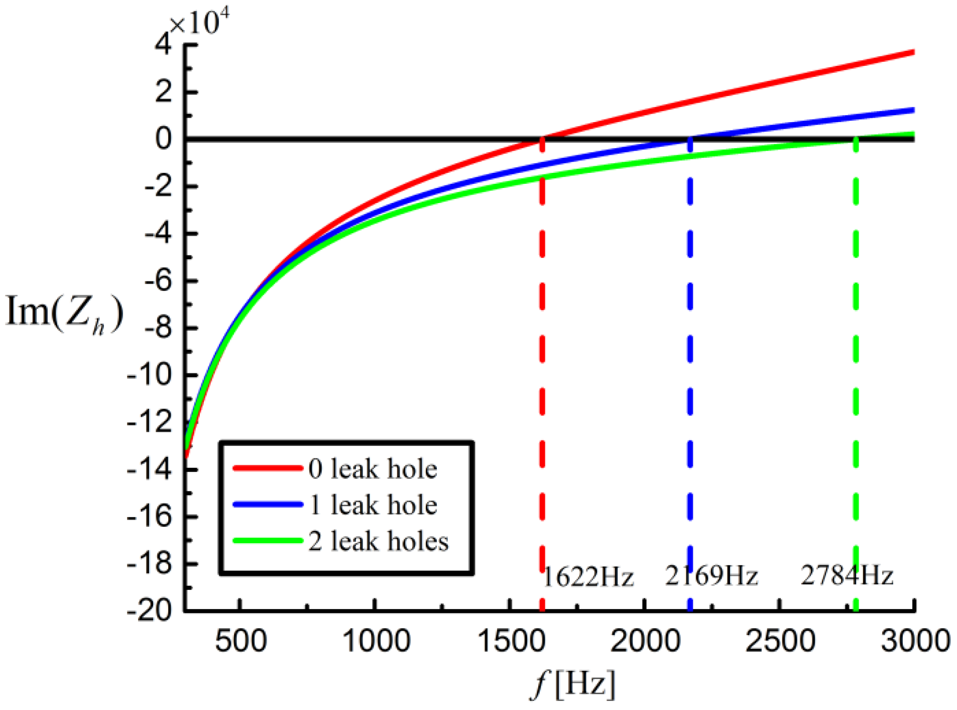
In fact, the influence of leakage on resonance frequency can be explained by the theory of acoustic impedance. Note that all the neck impedances can be considered as parallel, so the reciprocal of the overall impedance of the necks can be written as the sum of the reciprocal of impedance of each neck, given by
where is the impedance of the neck given in Equation (31). Thus, the overall impedance (unit , same as below) of the DHR device can be written as
where is impedance of the cavity given in Equation (31).
As shown in Figure 5, the imaginary part of the overall impedance changes with frequency and number of leak holes. With the increase of the number of leak holes, the slope of the impedance curve decreases, which will lead to an increase in frequency corresponding to the point with . Therefore, we can conclude that the existence of the leak holes always results in an increase in resonance frequency of the DHR system.
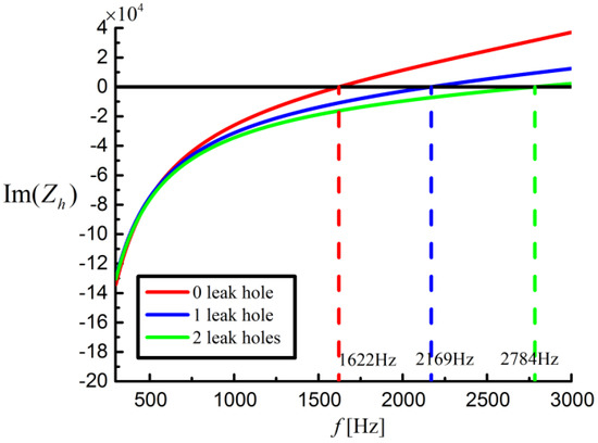
Figure 5.
Overall impedance vs. frequency.
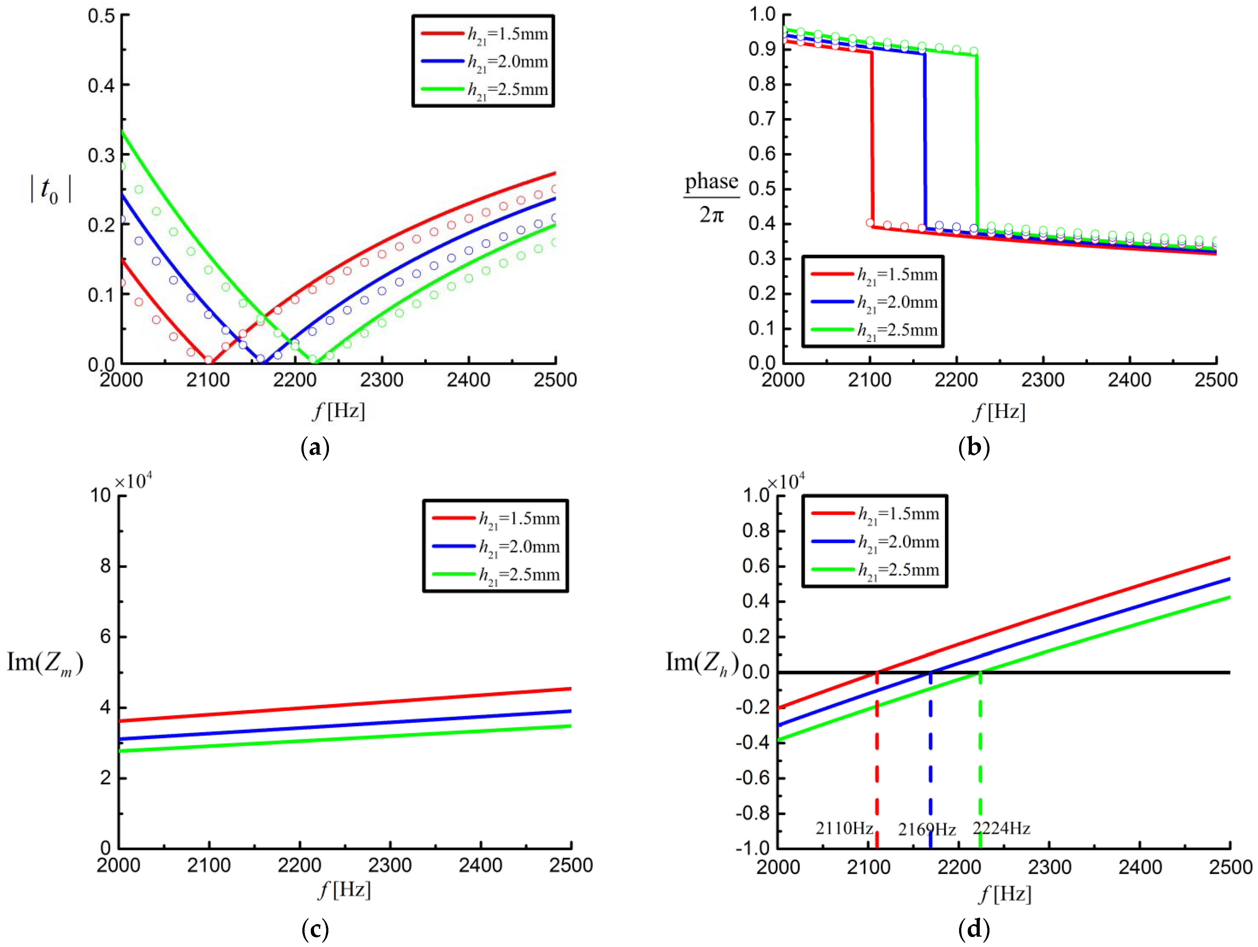
Next, the DHR device with one leak hole (see Figure 2b) is used to investigate the influences of different width of the leak hole on the transmission properties of the DHR device, the results are shown in Figure 6. In simulations, the width of the leak hole is taken as , , and , respectively. The other parameters are the same as those in Figure 2b. As can be seen from Figure 6a,b, the amplitude and the phase shift of the transmitted wave predicted by the theoretical formulas are consistent with the COMSOL results. The increase of the width of the leak hole will lead to an increase of resonance frequency of the system. The resonance frequency of the system will shift to higher values with the increase of the width of the leak hole.
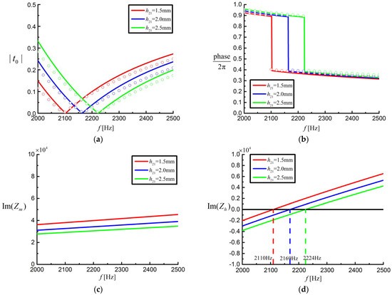
Figure 6.
Effects of the width of leak hole on transmission properties of the DHR device with one leak hole (see Figure 2b). The solid lines correspond to theoretical results, while the circle lines correspond to COMSOL predictions. (a) Amplitude vs. frequency; (b) Phase shift vs. frequency; (c) Impedance of the leak hole vs. frequency; (d) Overall impedance of the DHR device vs. frequency.
Figure 6c shows the variations of the imaginary part of the impedance of the leak hole with frequencies for different width of the leak hole. According to Equation (31), we can see that increases with frequency and decreases with the width of leak hole. The reduction of results in a decrease of the imaginary part of the overall impedance , which increases the resonance frequency, as shown in Figure 6d.
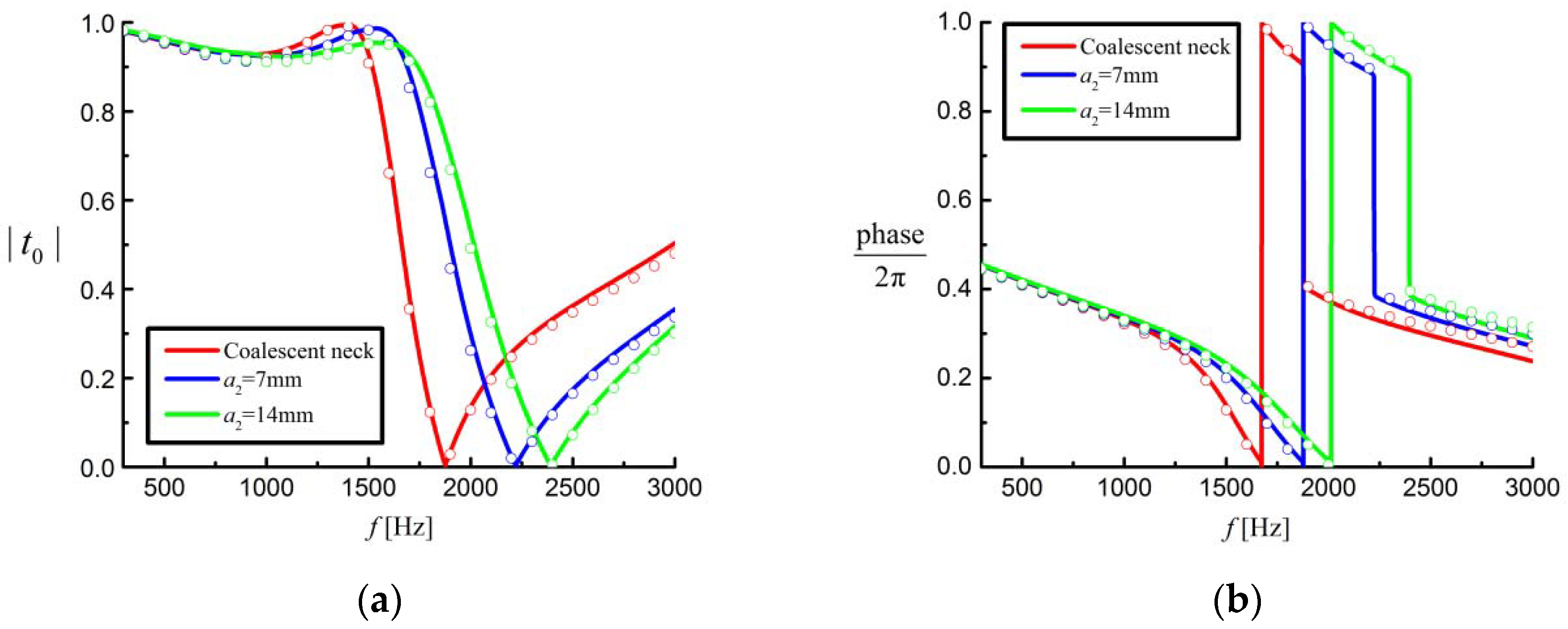
The results shown in Figure 7 are obtained by adjusting the distance between the leak hole and the main neck and keeping the position of the main neck unchanged. In simulations, the distance is taken as and , respectively, and the other parameters used are the same as those in Figure 2b. As a contrast, one neck whose width is the sum of the main hole and the leak hole is also calculated in Figure 7, which is drawn in red lines. As shown in Figure 7, the distance between the necks has an effect on the amplitude and phase shift of the transmission wave. As the distance between the necks increases, the amplitude curves and the phase shift curves move right, and the resonance frequency of the system increases, as shown in Figure 7a,b. Although in traditional theory, the distance between the necks has no effect on the resonance frequency, both the theory in this paper and the simulation results do not accord with this conclusion. As the distances between the necks become coalescent neck, 7 mm and 14 mm, the resonance frequencies become 1878 Hz, 2224 Hz, and 2396 Hz, respectively, which is a substantial difference that cannot be ignored. From Appendix A, we can see that the distance between the necks affects the value of the transfer matrix and finally affects the amplitude and phase shift. So, the theory in this paper can be used to calculate the transmission properties of DHR device in multi-neck condition more accurately comparing with traditional methods.
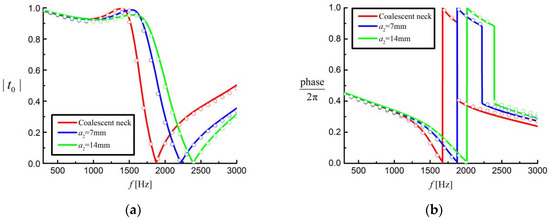
Figure 7.
Effects of the distance between the leak hole and the main neck on transmission properties of DHR with one leak hole. The solid lines correspond to theoretical results, and the circle lines correspond to COMSOL predictions. (a) Amplitude vs. frequency; (b) Phase shift vs. frequency.
4. Conclusions
In this paper, the analytical formulas to predict the acoustic transmission properties of a DHR device with leak holes are developed, which is based on the derived impedances of the holes and the cavity, and the coupling effects among these holes. Once transfer relations of acoustic wave from inlet to outlet of the duct are established, the transmission properties of the DHR device can be easily predicted. The accuracy and the effectiveness of developed theoretical formulas are verified by COMSOL simulations. The numerical results show that the number and the size of leak holes have important effects on the transmission properties of the DHR structure. The increase of the number and the width of the leak holes always shift the resonance to higher frequencies. In addition to the resonance frequency, the analytical method established in this paper can also quickly predict the amplitude and the phase characteristics of the transmission, which is of great significance for the leakage detection and localization of the gas pipeline system and DHR-based metasurface applications.
Author Contributions
Conceptualization, Y.O. and Y.Z.; methodology, Y.O. and Y.Z.; software, Y.O.; validation, Y.O. and Y.Z.; formal analysis, Y.O.; investigation, Y.O.; resources, Y.Z.; data curation, Y.O.; writing—original draft preparation, Y.O.; writing—review and editing, Y.Z.; visualization, Y.O.; supervision, Y.Z.; project administration, Y.Z.; funding acquisition, Y.Z. All authors have read and agreed to the published version of the manuscript.
Funding
This research received no external funding.
Institutional Review Board Statement
Not applicable.
Informed Consent Statement
Not applicable.
Data Availability Statement
The data presented in this study are available on request from the corresponding author.
Conflicts of Interest
The authors declare no conflict of interest.
Appendix A
Based on Equations (35), (36), (38), (39), (46) and (47), the following equations can be obtained
Equations (A1)–(A8) can be rewritten as the matrix form
where is a vector of length , whose elements are
The rest elements in vector are zero. is a matrix of order , whose elements are
where symbol means round down.
From Equations (A12)–(A20), we can obtain
From Equation (A21), and can be written as
where .
From Equations (A22) and (A23), the transfer relation from the first neck to the neck can be written in the form
where is a -dimensional matrix, whose elements are
References
- Wu, D.; Zhang, N.; Mak, C.M.; Cai, C. Hybrid noise control using multiple Helmholtz resonator arrays. Appl. Acoust. 2019, 143, 31–37. [Google Scholar] [CrossRef]
- Huang, S.B.; Fang, X.S.; Wang, X.; Assouar, B.; Cheng, Q.; Li, Y. Acoustic perfect absorbers via Helmholtz resonators with embedded apertures. J. Acoust. Soc. Am. 2019, 145, 254–262. [Google Scholar] [CrossRef]
- Lee, T.; Nomura, T.; Iizuka, H. Damped resonance for broadband acoustic absorption in one-port and two-port systems. Sci. Rep. 2019, 9, 13077. [Google Scholar] [CrossRef] [PubMed]
- Xia, J.P.; Zhang, X.T.; Sun, H.X.; Yuan, S.Q.; Qian, J.; Ge, Y. Broadband tunable acoustic asymmetric focusing lens from dual-layer metasurfaces. Phys. Rev. Appl. 2018, 10, 014016. [Google Scholar] [CrossRef]
- Li, J.F.; Shen, C.; Rubio, A.D.; Tretyakov, S.A.; Cummer, S.A. Systematic design and experimental demonstration of bianisotropic metasurfaces for scattering-free manipulation of acoustic wavefronts. Nat. Commun. 2018, 9, 1342. [Google Scholar] [CrossRef] [PubMed]
- Lan, J.; Zhang, X.W.; Liu, X.Z.; Li, Y.F. Wavefront manipulation based on transmissive acoustic metasurface with membrane-type hybrid structure. Sci. Rep. 2018, 8, 14171. [Google Scholar] [CrossRef] [PubMed]
- Yang, X.S.; Yin, J.; Yu, G.K.; Peng, L.H.; Wang, N. Acoustic superlens using Helmholtz-resonator-based metamaterials. Appl. Phys. Lett. 2015, 107, 193505. [Google Scholar] [CrossRef]
- Lan, J.; Li, Y.; Xu, Y.; Liu, X.Z. Manipulation of acoustic wavefront by gradient metasurface based on Helmholtz Resonators. Sci. Rep. 2017, 8, 10587. [Google Scholar] [CrossRef] [Green Version]
- Gong, K.; Wang, X.; Ouyang, H.; Mo, J. Supplementary material of tuneable gradient Helmholtz-resonator-based acoustic metasurface for acoustic focusing. J. Phys. D Appl. Phys. 2019, 52, 385303. [Google Scholar] [CrossRef]
- Park, C.M.; Lee, S.H. Propagation of acoustic waves in a metamaterial with a refractive index of near zero. Appl. Phys. Lett. 2013, 102, 241906. [Google Scholar] [CrossRef]
- Ning, L.; Wang, Y.Z.; Wang, Y.S. Active control of elastic metamaterials consisting of symmetric double helmholtz resonator cavities. Int. J. Mech. Sci. 2019, 153–154, 287–298. [Google Scholar] [CrossRef]
- Hu, X.; Ho, K.M.; Chan, C.T.; Zi, J. Homogenization of acoustic metamaterials of Helmholtz resonators in fluid. Phys. Rev. B 2008, 77, 172301. [Google Scholar] [CrossRef] [Green Version]
- Fang, N.; Xi, D.J.; Xu, J.Y.; Ambati, M.; Srituravanich, W.; Sun, C.; Zhang, X. Ultrasonic metamaterials with negative modulus. Nat. Mater. 2006, 5, 452–456. [Google Scholar] [CrossRef] [PubMed]
- Lee, S.H.; Wright, O.B. Origin of negative density and modulus in acoustic metamaterials. Phys. Rev. B 2016, 93, 024302. [Google Scholar] [CrossRef] [Green Version]
- Edalati, K.; Rastkhah, N.; Kermani, A.; Seiedi, M.; Movafeghi, A. The use of radiography for thickness measurement and corrosion monitoring in pipes. Int. J. Press. Vessels Pip. 2006, 83, 736–741. [Google Scholar] [CrossRef]
- Vargas-Arista, B.; Hallen, J.M.; Albiter, A. Effect of artificial aging on the microstructure of weldment on API 5L X-52 steel pipe. Mater. Charact. 2007, 58, 721–729. [Google Scholar] [CrossRef]
- Selamet, A.; Kim, H.; Huff, N.T. Leakage effect in Helmholtz resonators. J. Acoust. Soc. Am. 2009, 126, 1142. [Google Scholar] [CrossRef] [PubMed] [Green Version]
- Lee, I.; Jeon, K.; Park, J. The effect of leakage on the acoustic performance of reactive silencers. Appl. Acoust. 2013, 74, 479–484. [Google Scholar] [CrossRef]
- Langfeldt, F.; Hoppen, H.; Gleine, W. Resonance frequencies and sound absorption of Helmholtz resonators with multiple necks. Appl. Acoust. 2019, 145, 314–319. [Google Scholar] [CrossRef]
- Zhao, H.F.; Xiao, X.; Xu, P.; Zhao, T.C.; Song, L.G.; Pan, X.X.; Mi, J.C.; Xu, M.Y.; Wang, Z.L. Dual-tube Helmholtz resonator-based triboelectric nanogenerator for highly efficient harvesting of acoustic Energy. Adv. Energy Mater. 2019, 9, 1902824. [Google Scholar] [CrossRef]
- Liang, W.; Zhang, L.B.; Xu, Q.Q.; Yan, C.Y. Gas pipeline leakage detection based on acoustic technology. Eng. Fail. Anal. 2013, 31, 1–7. [Google Scholar] [CrossRef]
- Mostafapour, A.; Davoudi, S. Analysis of leakage in high pressure pipe using acoustic emission method. Appl. Acoust. 2013, 74, 335–342. [Google Scholar] [CrossRef]
- Jin, H.; Zhang, L.B.; Liang, W.; Ding, Q.K. Integrated leakage detection and localization model for gas pipelines based on the acoustic wave method. J. Loss Prev. Process Ind. 2014, 27, 74–88. [Google Scholar] [CrossRef]
- Li, Y.; Qi, S.B.; Assouar, M.B. Theory of metascreen-based acoustic passive phased array. New J. Phys. 2016, 18, 043024. [Google Scholar] [CrossRef]
- Lee, I.; Selamet, A.; Huff, N.T. Acoustic impedance of perforations in contact with fibrous material. J. Acoust. Soc. Am. 2006, 119, 2785–2797. [Google Scholar] [CrossRef]
- Qi, L.H.; Yu, G.K.; Wang, X.L.; Wang, G.B.; Wang, N. Interference-induced angle-independent acoustical transparency. J. Appl. Phys. 2014, 116, 234506. [Google Scholar] [CrossRef]

Publisher’s Note: MDPI stays neutral with regard to jurisdictional claims in published maps and institutional affiliations. |
© 2022 by the authors. Licensee MDPI, Basel, Switzerland. This article is an open access article distributed under the terms and conditions of the Creative Commons Attribution (CC BY) license (https://creativecommons.org/licenses/by/4.0/).