Article

Geometrical Planning of the Medial Opening Wedge High Tibial Osteotomy—An Experimental Approach

by
Nicolae Florin Cofaru
1,
Valentin Oleksik
1,*,
Ileana Ioana Cofaru
1,
Carmen Mihaela Simion
1,
Mihai Dan Roman
2,
Ioana Codruta Lebada
2 and
Sorin Radu Fleaca
2
1
Faculty of Engineering, Lucian Blaga University of Sibiu, 550024 Sibiu, Romania
2
Faculty of Medicine, Lucian Blaga University of Sibiu, 550024 Sibiu, Romania
*
Author to whom correspondence should be addressed.
Appl. Sci. 2022, 12(5), 2475; https://doi.org/10.3390/app12052475
Submission received: 19 November 2021 / Revised: 21 February 2022 / Accepted: 25 February 2022 / Published: 27 February 2022
(This article belongs to the Special Issue Biomechanical and Biomedical Factors of Knee Osteoarthritis)

Abstract

:
This article presents an experimental approach to the geometrical planning of the medial opening wedge high tibial osteotomy surgery which, as it is known, is an efficient surgical strategy quite widely used in treating knee osteoarthritis. While most of the published papers focus on analyzing this surgery from a medical point of view, we suggest a postoperative experimental evaluation of the intervention from a biomechanical point of view. The geometrical planning and, more specifically, the determination of the point of intersection between the corrected mechanical axis and the medial-lateral articular line of the knee, is a problem quite often debated in literature. This paper aims to experimentally investigate the behavior of the tibia with an open wedge osteotomy fixed with a locking plate, TomoFix (DE Puy Synthes), taking into account two positions of the mechanical axis of the leg on the width of the tibial plateau, measured from medial to lateral at 50% and 62.5% (Fujisawa point), respectively. The variations of the force relative to the deformation, strains, and displacements resulting from the progressive loading of the tibial plateau are studied. The research results reveal that using the Fujisawa point is better for conducting the correction not only for medical reasons, but also from a mechanical point of view.

1. Introduction

Osteoarthritis (hereinafter OA) is a fairly common condition that occurs among adults worldwide [1,2,3,4,5]. Most often, this disease affects the medial area of the knee by progressively wearing off the articular cartilage in this compartment [6,7] and the consequences are the appearance of pain and loss of joint function. This type of wear causes a varus-type axial deviation [8,9,10] which increases the load in the same medial area [11] of the knee which is already damaged.
The existing mechanical loads at the tibiofemoral joint are quite high, exceeding the body weight several times [1]. When the body weight is supported by one leg while walking, 55–75% of these loads are applied to the medial compartment of the knee [2,3,4]. Due to these loads, the wear of the intra-articular cartilage and the increase in the varus-type axial deviation progress quite fast, being later amplified by the axial deviations that are likely to appear [12].
From a geometric point of view, as can be seen in Figure 1b, osteoarthritis involves decreasing the intra-articular space in the medial area and implicitly increasing it in the lateral area, moving the point of intersection between the medial-lateral articular line and the mechanical axis of the leg towards the medial area. In the case of a healthy knee, the mechanical axis of the leg (the blue line shown in Figure 1a), which joins the center of the femoral head with the center of the tibiotalar (ankle) joint, passes right through the center of the knee [13]. The wear of the cartilage in the medial area causes the mechanical axis to move towards this area (blue line in Figure 1b), a displacement which is proportional to the degree of wear of the cartilage.
As described above, the knee loading will be defective, with a high probability that the cartilage wear will progress and the disease will worsen.
One of the most effective surgical strategies meant to stop this process and restore a proper knee loading is the open wedge high tibial osteotomy (hereinafter OWHTO) [13,14]. This intervention is especially suitable for young and active patients who desire a speedy recovery in order to return to physical activities conducted prior to the disease and who seek the postponement of more complex surgeries, such as total or unicompartmental knee replacements [15].
The purpose of the OWHTO surgery consists in realigning the mechanical axis of the leg so that it no longer crosses the worn medial compartment [16,17], implicitly obtaining a correct loading of the joint.
Figure 1c presents the steps that are to be taken in order to correct this axial deviation, using one of the most frequently used methods for geometrically planning the OWHTO, the Minniaci method [17].
The first step consists in drawing a line (orange) that passes through the center of the femoral head and through the point situated on the knee joint line, through which the mechanical axis of the leg should pass after the correction. It is to be noted that the orange line does not intersect the center of the tibio-talar joint (the S point on the blue line) at the tibia level. The following steps have, as a final objective, the transfer of the center of the ankle in the point S’ situated on the orange line (Figure 1c).
The second step consists in establishing two points: the hinge point B called CORA (center of rotation of the angulation) and the O point, situated on the medial cortical of the tibia, and called the initiation point of the cut of the osteotomy plane. The position of these points results from the recommendations that have been made on the matter in literature [18]. The osteotomy plane follows the BO line in the transversal plane and is perpendicular to the limb frontal plane (Figure 1c).
The third step consists in performing the correction of the deviation by creating an osteotomy wedge OBO’, with an angle α at its tip (Figure 1c). Performing this wedge causes the center of the tibio-talar joint to move in the point S’ from the orange line, and thus, the geometrical planning of the OWHTO is finalized.
As can be observed from the above, the most important step—on which the following steps are dependent—is the first one, when the intersection point of the orange line (Figure 1c) with the knee joint line is established.
Strictly from a geometric point of view, as stated above, this mechanical axis is considered aligned when it intersects the medial-lateral articular line at a point located in the middle of the joint—the red line in Figure 1b.
In fact, there is a consensus in the surgical practice [18,19,20,21,22] regarding the requirement to make an overcorrection through which the corrected mechanical axis would intersect the joint not through the middle, but through points located closer to the lateral area of the knee (the yellow and orange lines in Figure 1b). This overcorrection will generate an offload on the worn medial compartment and a transfer of the load to the lateral area, thus stopping the progress of the osteoarthritis [23,24].
Regarding the optimal positioning of the point on the medial-lateral articular line through which the mechanical axis of the leg will pass after the OWHTO, there is no unitary opinion.
There are, however, a few established approaches [18,19,20,21,22,23,24,25,26].
One of the widely used over-corrections in surgical practice is the one suggested by Fujisawa, Y. et al. [18,19], indicating a position located at approximately 62–66% of the distance measured from the medial to the lateral area, more specifically 62.5%—the orange line in Figure 1b, a position known as the Fujisawa point.
Other research highlights the need for a correlation of the corrected mechanical axis position with the degree of cartilage wear. Thus, if one-third of the cartilage is lost, the mechanical axis should pass at 55–57.5% of the distance measured from the medial; if two-thirds of the cartilage is lost, the axis should pass at 60–62.5% of that distance, while in the case of an almost total cartilage wear and loss, the axis should pass at 65–67.5% [20].
Following a study conducted on 116 patients [21] with medial compartment knee osteoarthritis undergoing treatment with OWHTO, it was concluded that an optimal overcorrection is one where the mechanical axis passes through the tibial plateau through a point located at 71.93%, measured from the medial to the lateral area.
Even though there were authors [22] who recommended even higher values—75% (yellow line in Figure 1b)—an excessive overcorrection is not recommended, as it can lead to degeneration and wear in the lateral compartment which will cause other dysfunctions [18,25,26]. This happens because it is proven that with each 1 mm transfer of the position of the intersection point of the mechanical axis with the medial-lateral articular line, a load transfer of up to 41 N from the medial compartment to the lateral compartment takes place [11]. This will result in considerable loads on the lateral compartment and implicitly to the appearance of pain, decreased knee mobility, and the need to opt for a prosthetic, which can be inserted with a total or partial knee arthroplasty [25,26]. The working hypothesis of this study consists in experimentally verifying the fact that using an overcorrection for the position of the leg’s mechanical axis when performing OWHTO leads to a better biomechanical stability of the joint.
Consequently, the main purpose of this research is the optimization of the geometrical planning of the OWHTO, by taking into account the optimal position of the intersection point between the medial-lateral articular line and the corrected mechanical axis.

2. Materials and Methods

2.1. Experimental Research on the Study of the Postoperative Behavior of the Tibia-Osteosynthesis Plate Assembly following the Opening Osteotomy
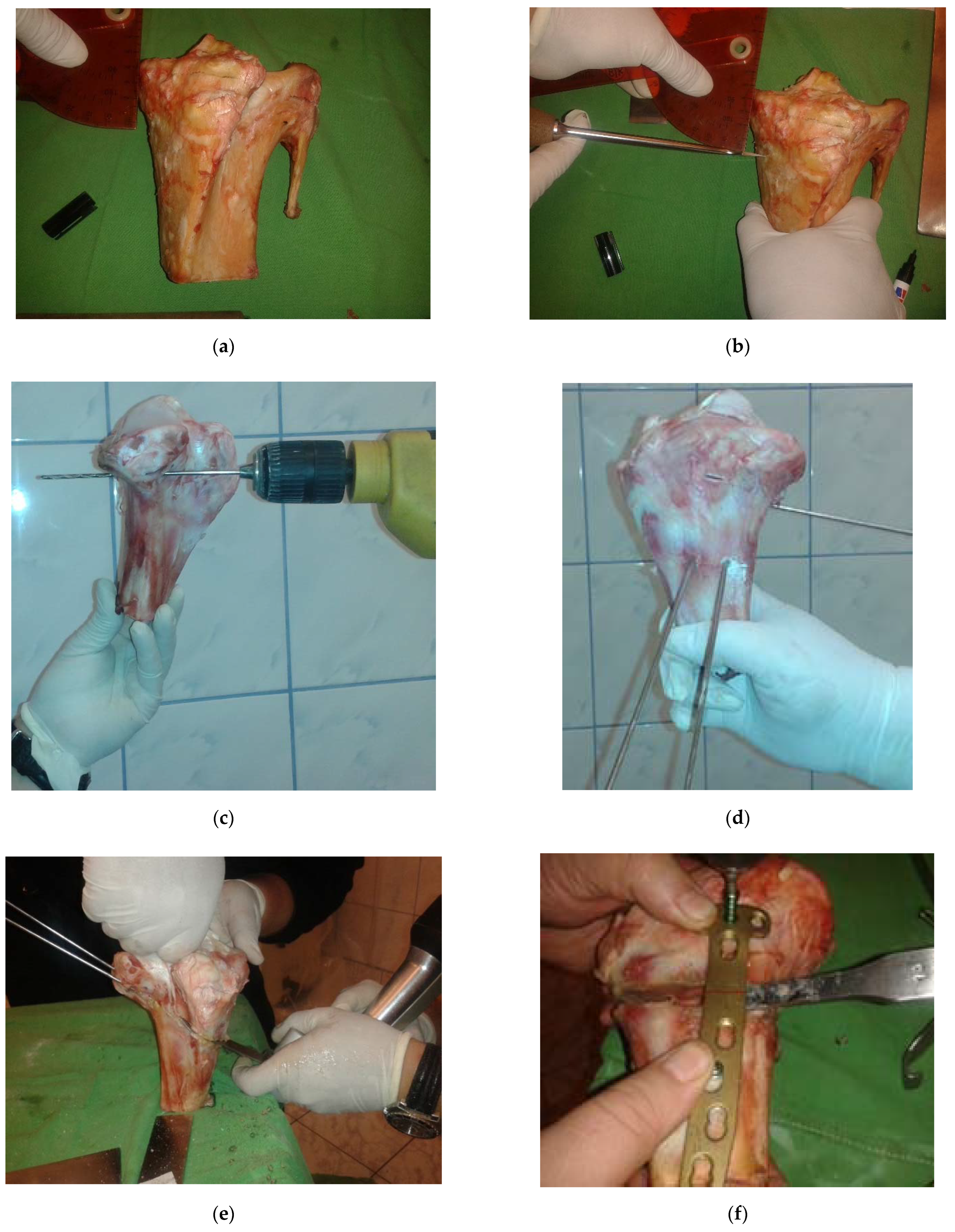
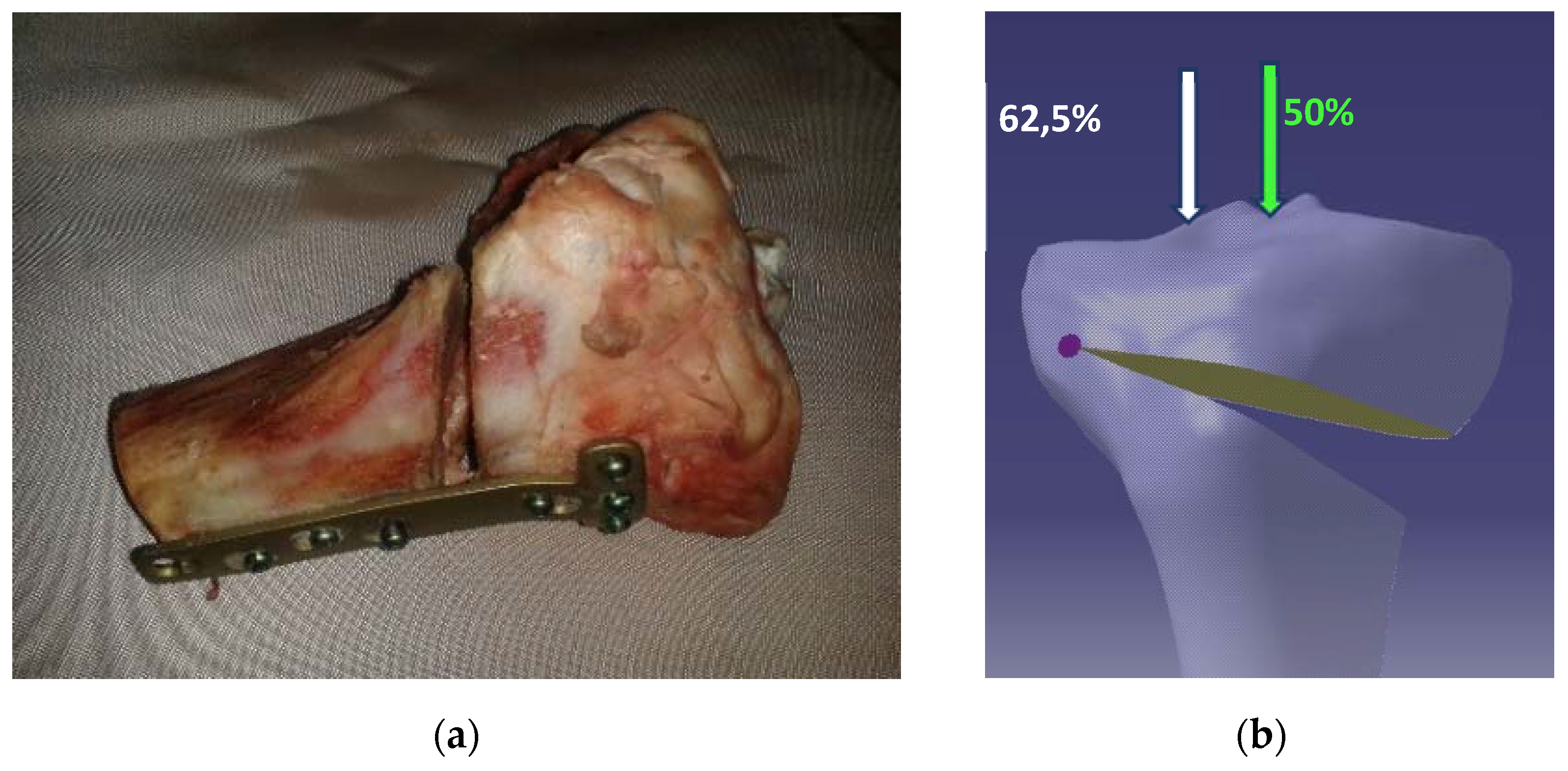
In this chapter, an experimental program will be conducted, aimed at studying the postoperative behavior of the tibia-osteosynthesis plate assembly after performing high opening tibial osteotomies.
The objective of the experiment is to evaluate the behavior of the tibia with an open wedge osteotomy fixed with a locking plate, TomoFix (DE Puy Synthes), taking into account two positions of the mechanical axis of the leg on the width of the tibial plateau. The two positions are: the theoretical position of correction, situated in the middle of the medial-lateral distance (red line in Figure 1b); and the Fujisawa point (orange line in Figure 1b), which is the overcorrection position most frequently used in surgical practice.

2.1.1. Specimens

The specimens used in the experimental program are juvenile bovines’ tibias. Juvenile bovine bones are very frequently used in biomechanical studies due to the fact that bovine bones are most similar—as far as their behavior is concerned—to human bones [27,28]. Two tibias were used, one for each position of the corrected mechanical axis (50%, 62.5%).
The tibias were procured from an authorized butchery (i.e., that has all the necessary approvals), that sells meat and meat products. Hence, the animal was not slaughtered for the purpose of experimental research (but rather for a commercial one). The specimens were acquired on the day of slaughter and were taken from the same animal in order to ensure a very good similarity of the two specimens.
The OWHTO surgery was performed on the two tibias—the steps of the surgery have been presented in Figure 2a–f.
After cutting the osteotomy plane using appropriate surgical instruments and in accordance with the surgical procedure used for real surgeries (Figure 2a–f), the correction angle is performed and then stabilized with a plate, especially designed for this type of surgery, called TomoFix.
The plate that was used is of the following type: TomoFix tibial head plate medial, proximal (MHT) standard stature versions [17]. The plates 44.834S are made of pure titanium. In the proximal section there are 4 threaded holes and in the distal section there are 2 combination and 2 locking holes.
The angular correction was performed by means of a spacer calibrated at 10 mm (Figure 2f). Figure 3a shows the sample of the tibia with the fastened TomoFix plate.
The purpose of the experiment is to observe the variation of the loading force in relation to the deformation and the state of the local strain and displacements as a whole for both the discussed situations (Figure 3b).

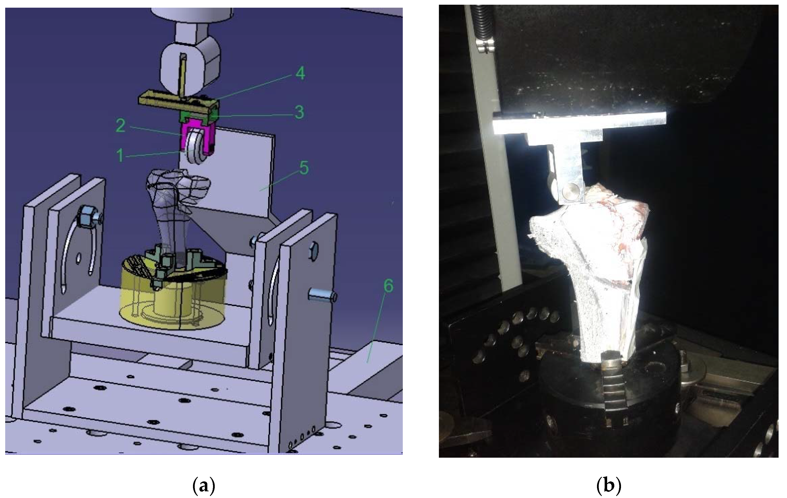
2.1.2. Experimental Stand

In order to carry out the experimental tries, a modular experimental stand was designed and built, which allows a generalized approach to the experimental problems regarding high tibial osteotomy.
As can be seen in Figure 4a the lower subassembly of the stand, mounted on the plate of the machine, is made of two U-shaped frames providing the possibility to adjust the angle up to 120° in each direction. In this regard, it is possible to position the tibia, the orientation and fixing functions being provided by a self-centering clamping device. For this experiment, the tibia is fastened upright.
The superior subassembly mounted on the mobile crosshead of the testing machine, due to its construction, is suitable for both the intraoperative study of the closing high tibial osteotomy and the postoperative study of the opening high tibial osteotomy, as shown in this experiment.
The main functional element of the stand is roller 1 (Figure 4a) which will press on the upper part of the tibia. The cylindrical roller 1 is fastened by a fork head bolt 2, which is guided in the connecting part 3 at its upper side, allowing it to move forwards and backwards. In order to perform left–right movements, part 3 is guided into the guiding plate 4. Parts 5 and 6 have the purpose of controlling the position of the tibia. Orientating the posterior part of the tibia on the vertical plane of part 5 guarantees the verticality of the specimen. Plate 4 also has a prismatic area dimensioned in such a way that it can be attached to the fastening device in the area of the mobile crosshead of the machine. The two perpendicular movements that the roller can perform allow the application of force in the desired positions. The two translational joints are fixed during the loading phase. Figure 4b shows the experimental stand physically built and prepared for the experiment. It can be observed that the second assembly, the tibia–TomoFix plate assembly, is vertically positioned in the self-centering fixture located on the ‘U’-type frame.
The stand is mounted on the INSTRON 5587 testing machine, which has the following characteristics:
  • maximum load capacity of 300 kN
  • recording of the force with a precision corresponding to class ASME 4-E or DIN 51,221 Class 1
  • speed of the mobile crosshead ranging from 0.001 to 500 mm/min
  • machine plate surfaces of 1403 × 851 mm
  • Bluehill 2.0 software
The Instron 5587 tensile-compression machine has a load cell with +/− 0.25% linearity and +/− 0.25% repeatability for reads in 0.4–100% of its capacity. The displacement control loading condition has been applied with a 5 mm/min rate.
Regarding the planning of the experiment, the two tests were performed successively on the two tibias. With the first one, the force was applied on the center of the knee joint (tibia) while in the second test, it was applied on the Fujisawa point. The force acting on the tibia reached the maximum value of 1000 N. This value was chosen because the studied literature showed that, while walking, the knee joint can be subjected to forces exceeding 2 or 3 times the weight of the body [1].
The response functions of the experiment are the following: the variation of the force relative to the deformation and the determination of the main deformations and displacements during the application of the loads.
The facilities provided by the “INSTRON 5587 testing machine” are appropriate for studying the variation of the force, but in order to determine the main strains and displacements of the test specimens of the bovine tibia subjected to the compression test, an optical system was required. In this sense, the Aramis system was used, which is a system that—by means of two high-resolution cameras (charged coupled device sensors)—measures the strains of the graphite network applied on the studied surface.
This system enables real-time measurements of the strains that occur in the bovine specimens subjected to compression.
The optical strain measurement system is equipped with its own software that performs the command and the control of the system, as well as the acquisition and the processing of data, such as: image recording control and post-processing, automatic scanning of a series of images, 2D and 3D views, statistical analysis, or data export.
The Aramis 2M optical system used for determining the strains is produced by Gom GmbH and has two lenses with a 50 mm focal length. The optical resolution of the cameras is 1600 × 1200 and the maximum acquisition rate is 12 Hz. For the experimental determinations of the strains, a 1 Hz acquisition rate was chosen and a f2.8 aperture was selected in order to increase the luminosity. The cameras were positioned at 900 mm from the measured bone. For calibrating the Aramis device, a calibration object (CP120 × 96) was chosen, which determines the calibrated measurement volume of 125 × 95 × 70 mm3. The calibration deviation was 0.018 pixels with a scale deviation of 0.001 mm. The strain accuracy of the optical device is up to 0.01%. The Aramis dedicated software allows for automatic image correlation after the experiment has concluded.
The main advantages of using this measurement system are the following: it provides complete three-dimensional information on the coordinates, displacements, strain distribution, etc.; it uses a non-contact measurement method; the conducted analysis is independent of the nature of the material and the local accuracy; and resolution is high (up to ± 0.01%).
Basically, a thin layer of silvery, fast-drying opaque paint was applied to the studied bovine specimens to prevent unwanted reflections. The specimen was allowed to dry for a few minutes and, after drying, it was covered in a fine black graphite powder. Figure 5 shows the bovine specimens prepared for the tests in the two cases: loading the Fujisawa point—Figure 5a; and loading the medial area—Figure 5b. The experimental results will be presented in the next chapter.

3. Results

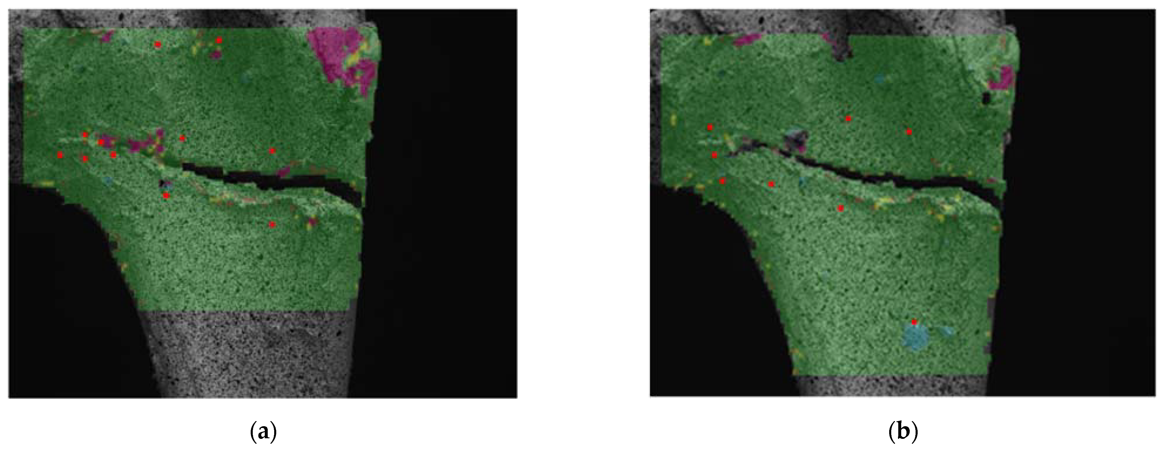
Experimental Results Regarding the Study of the Postoperative Behavior of the Tibia-Osteosynthesis Plaque Assembly after Performing an Opening Osteotomy

The variation of the force relative to the deformation for the experimental tests presented in the previous chapter is shown graphically in Figure 6 and Figure 7. The first experiment was performed with an 8 mm shift of the roller from the plane of symmetry of the machine. This shift of the roller materializes the Fujisawa point, taking into account the dimensions of the tibia-specimen.
A smooth increase in the compression force, but a good stability of the system can be observed in Figure 6. An approximately linear variation of the displacement up to the value of 1 mm can be observed initially for small forces up to 100 N. The variation curve then follows a parabolic rate up to a maximum displacement of 2.6 mm. The maximum input load is of 1000 N. The graphical processing of the experimental data was performed using the Instron machine software.
When the load is applied in the middle of the knee joint (Figure 7), the diagram in Figure 7 shows behavior similar to the previous linear variation for loads up to 100 N, also followed by a linear increase, but with a higher slope. The system is less stable than the first one, with maximum displacements of up to 3.4 mm.
The strains and displacements were assessed by means of the Aramis optical strain measurement system, and Figure 8, Figure 9 and Figure 10 show the major strain ε1, the minor strain ε2, and the total displacements for four loading stages, for both medial and radial loading.
The following can be observed after analyzing Figure 8, Figure 9 and Figure 10:
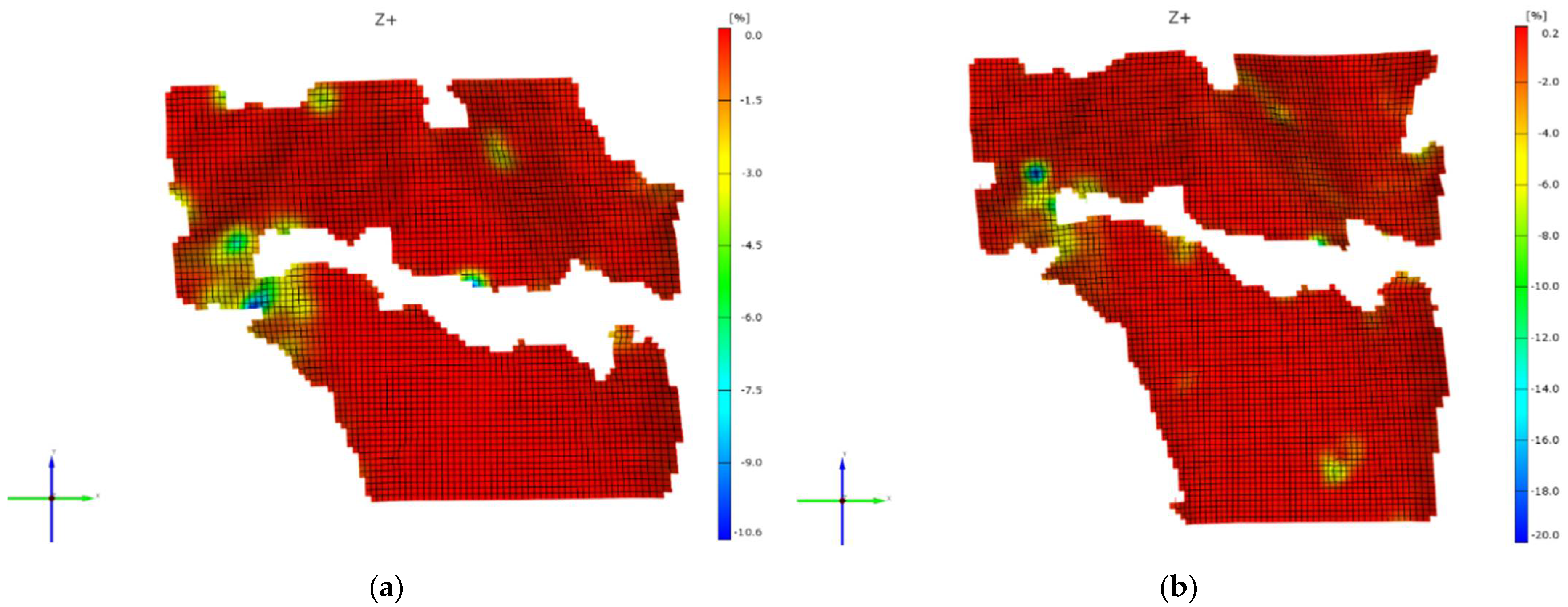
  • The predominant strains are the compression strains (minor strain ε2, the maximum values being 20% for medial loading and 10.6% for offset loading).
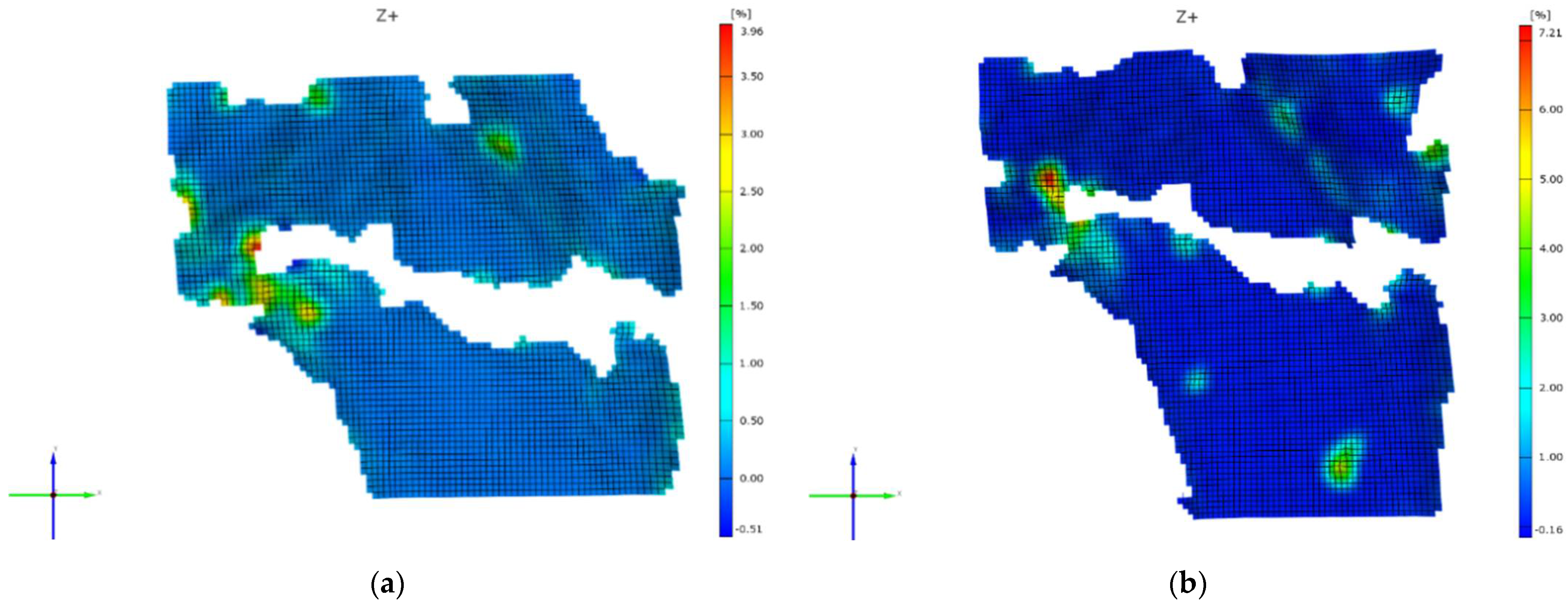
  • The major strain ε1 has the maximum values of 7.21% in the case of medial loading and 3.96% in the case of offset loading.
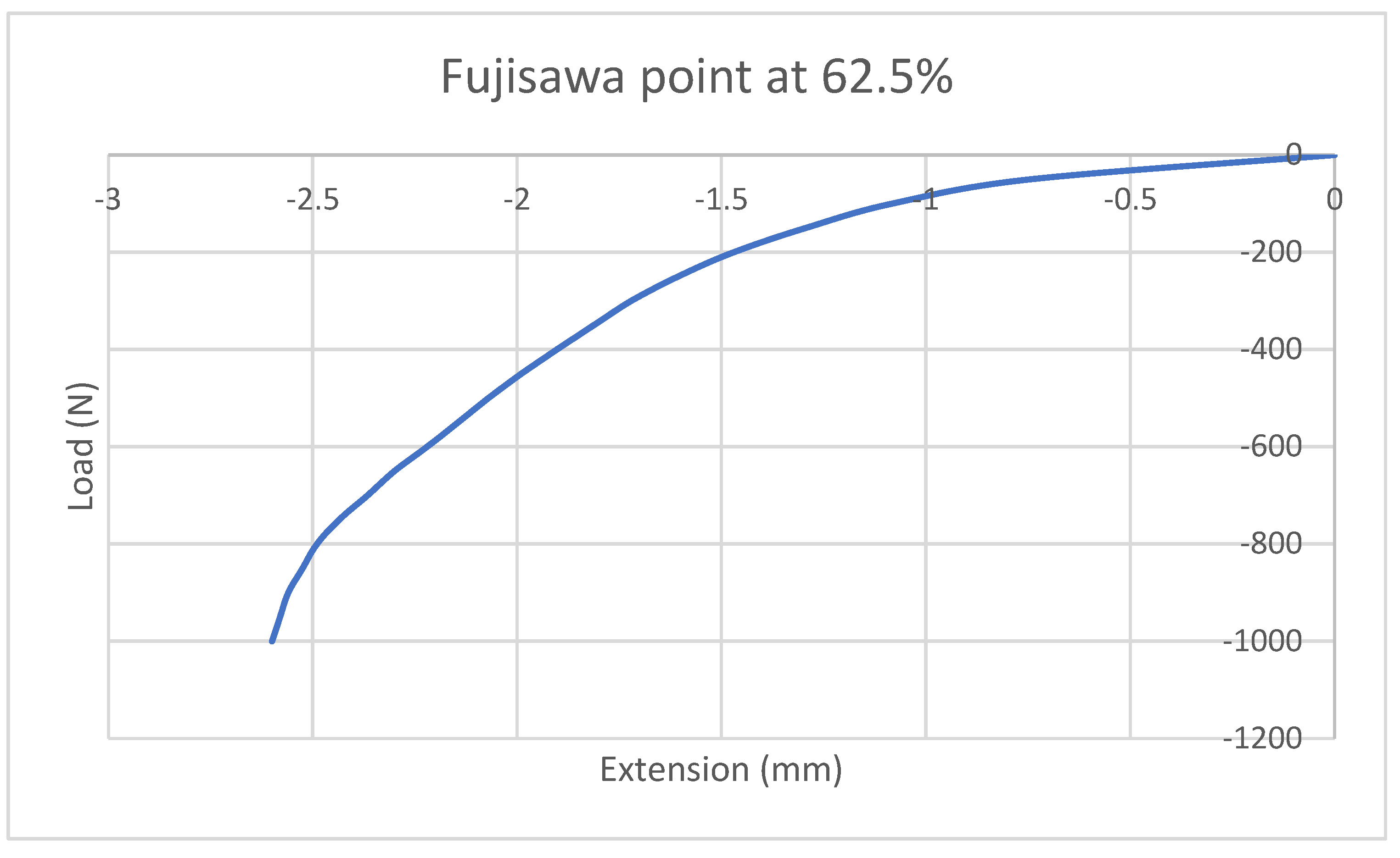
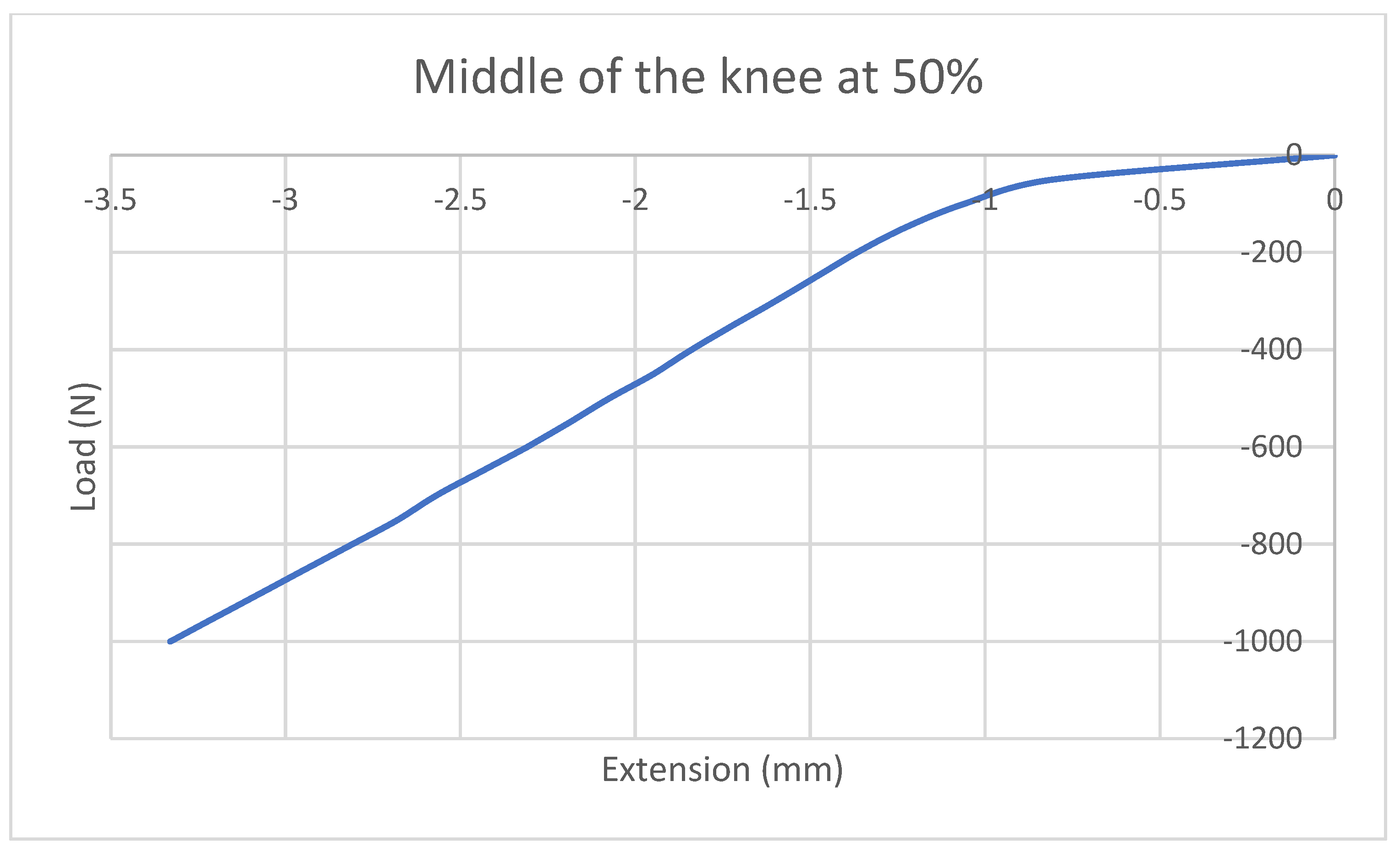
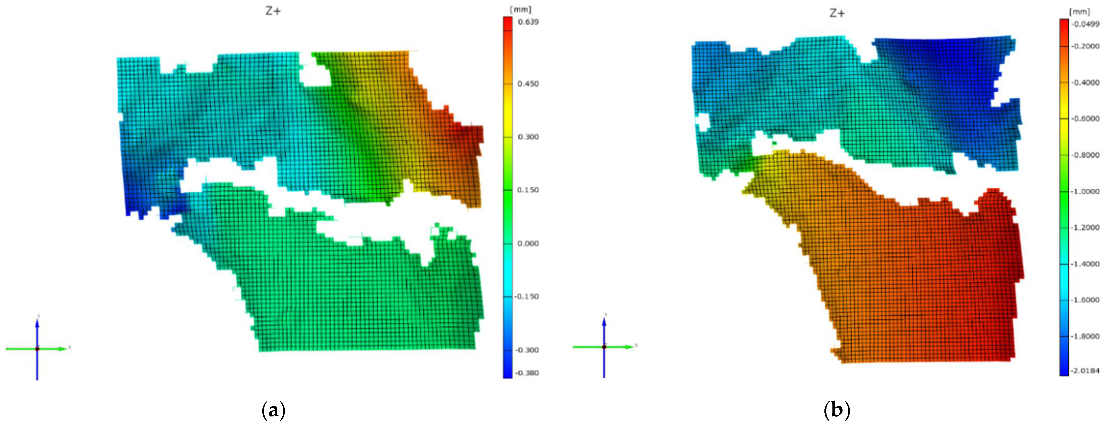
  • From the point of view of the displacements that occur, it can be easily seen that the maximum values in the vertical direction (Oy) are reached during the medial loading −2.01 mm, while at offset loading (Fujisawa point) the maximum value of the displacements is 0.639 mm in the positive direction of the Oy axis. This is due to the fact that the stress is applied to the left of the tibial plateau and the stressing force tends to twist the upper part of this plateau in the trigonometric direction.
Figure 8, Figure 9 and Figure 10 show the experimental results for the loading stage of 100%. In the experiment, successive evaluations of the strains for four loading stages—namely 25%, 50%, 75%, and 100% of the total loading stroke—were also performed. The results are shown in Table 1.
Figure 11 and Figure 12 show the variations of the major strain ε1 and minor strain ε2 during medial and offset loading (Fujisawa point) in the four loading stages.
As shown in Figure 11, the values of the major strains for the stage of the stroke of 25%, 50%, and 75% are almost double in the case of medial loading. For the stroke of 100%, the values are closer together, but with a higher value for this loading.
In the case of the minor strains which, as mentioned previously, are the predominant strains, the superiority of the loading in the medial point of the knee is evident. Thus, if for the stroke of 100% the values of the minor strain are almost double in the case of medial loading, for the other loading stages this difference is even greater, reaching values of over 300% for the strokes of 50% and 75%, respectively.

4. Discussion

The geometric planning of the OWHTO in general and the optimal position of the intersection point between the medial-lateral articular line and the corrected mechanical axis are approached in literature by performing preoperative and postoperative evaluations. The preoperative evaluations are usually performed through 3D modeling and CAE (computer aided engineering) simulations and seek the optimization, from a geometric point of view, of the geometrical parameters that characterize the correction (CORA, initiation point of the cut of the osteotomy plane, correction angle) [29], as well as the optimization of the stability of the assembly consisting in the tibia—on which the OWHTO was performed, and the TomoFix osteosynthesis plate [30,31,32].
A preoperative method can also consist of synthesizing clinical trials as presented in [21], as previous experiences regarding the evolution and the stability of the intervention can offer clues for optimizing the geometrical planning of the surgery.
Postoperative experimental evaluations, regarding the stability of the joint on which the surgery occurred, were performed less frequently because they present a series of limitations. The most important one consists in the fact that the experimental tries cannot be performed ‘in vivo’ on human bones, thus it is necessary to perform the surgery on bovine juvenile bones that have a very similar mechanical behavior. Despite these limitations, the fact that the evaluations are actually performed by using experimental methods on a real bovine bone–TomoFix plate assembly, they can provide a better indication of the surgical outcome, as they provide actual feedback on the behavior of such an assembly. A very important element in this sense is the fact that the bovine bone used has a heterogeneous structure (cortical and spongy), similar to human bone.
The research carried out in the present paper is considered to contribute to the optimization of the geometric planning of the medial opening wedge high tibial osteotomy. The experimental results are a considerable argument in this regard.
The results obtained in the experiments provide consistent information on the choice of the optimal position of the intersection point between the medial-lateral articular line and the corrected mechanical axis.
The variations of the force relative to the deformation shown in Figure 6 and Figure 7 reveal a better stability of the system in the case of the intersection at the Fujisawa point, resulting in a displacement smaller by almost one millimeter compared to the midpoint of the joint. The parabolic variation between force and deformation in the case of the Fujisawa point also indicates a better load-bearing capacity and—as can be seen from the graph for high value forces (700–1000 N)—the increase in the displacements is small (approximately 0.23 mm). In the case of the other loads, at the same range of variation of the force, the increase in the displacements is 4 times higher.
The analysis of the local strains and displacements leads to similar findings. It is easily noticed that the highest stresses in terms of mechanical strength occur when the stress is closer to the middle of the tibial plateau, both strains (major and minor) doubling their values compared to the offset loading (in Fujisawa point) under the conditions of the same 1000 N load.
In both medial and offset (Fujisawa point) loadings, the maximum values of the main and secondary strains appear in the hinge area of the OWHTO.
The progressive evaluation of the major and minor strains during medial and offset loading corresponding to a stroke of 25% (a), 50% (b), 75% (c), and 100% (d) of the total loading stroke is important, taking into account the fact that the load in the knee is variable while walking.
Another conclusion is that an overcorrection of the mechanical axis is beneficial and gives better stability in all four stages of loading.
In conclusion, it should be noted that medial loading leads to larger strains and displacements that can cause the appearance of cracks or even fractures. It is recommended that the mechanical axis of the lower limb passes through the Fujisawa point, located 62.5% from the medial extremity of the knee.
This issue is worth studying in future research, taking into account the studies conducted on topics, such as the multi-objective optimizations of the fixing plate, that can be found in paper [29] or similar research conducted in papers [33,34,35,36,37].
The data obtained from this experimental research contribute to the optimization of the geometric planning of the medial opening wedge high tibial osteotomy.
An important technical detail in performing OWHTO is related to the stability of the osteotomy, in direct relation with the consolidation of the osteotomy gap, postoperative care, and patient’s quality of life [38,39]. The stability of the osteotomy gap is related to the fixation implant design, geometry of the osteotomy, and correction of the mechanical axis of the limb [40,41,42,43,44]. The anatomy of the osteotomy cut also influences its stability through different variables: angle of the osteotomy, presence of a hinge fracture, monoplanar or biplanar, proximal or distal from the anterior tibia tuberosity [29,45].
The importance of the stability of the lateral hinge in the functional and clinical out-come of OWHTO is largely recognized. Lateral hinge fracture can occur during surgery or in the first six weeks after surgery [46]. Schrotter hypothesized that increasing the stresses induced by weightbearing on a reduced surface can play a major role in decreasing the stability of the osteotomy gap [47]. Therefore, indirect intraoperative and postoperative compression of the gap is recommended to prevent hinge instability. The indirect compression can be achieved intraoperatively by means of a temporary lag-screw and maintained with a locking compression plate, similar with the plate used in the presented experiment [48]. All described techniques increase intraoperative stability but there are no data suggesting that they can prevent secondary postoperative occurrence of a hinge fracture.
The results of the present experiment show that indirect postoperative hinge compression during weight bearing can be achieved by mechanical correction through the Fujisawa point.

5. Conclusions

There are several biomechanical studies analyzing the stability in OWHTO. However, the studies are focused on the stability related to the type and method of the fixation device, lateral hinge fracture, or filling the osteotomy gap with a bone substitute equivalent to the size of the opening [49]. To our knowledge, this is the first experimental model that allows a biomechanical evaluation of the stability related to the optimal position of the intersection point between the medial-lateral articular line and the corrected mechanical axis.
An important limitation of this study is that only a single set of measurements was achieved, as there was no way of obtaining identical tibia specimens in terms of size, geometry, and even mechanical characteristics that would allow the replication of the experimental trials and the statistical analysis of the results. However, the fact that both the variation of the force relative to the displacement and the evaluation of the major and minor strains in four loading stages—namely 25%, 50%, 75%, and 100% of the total loading stroke—demonstrated that the optimal position of the intersection point between the medial-lateral articular line and the corrected mechanical axis is at the Fujisawa point. This double assessment leads to the assumption that the results obtained are not affected by errors and have a reasonable degree of generality.
Correcting the mechanical axis of the limb in opening wedge high tibial osteotomy through the Fujisawa point in patients with medial osteoarthritis of the knee provides increased stability compared with correction through the center of the knee. Increased stability allows decreased nonunion rate and early mobilization of the patients with improvement of their quality of life.
No live animal or human studies were carried out by the authors in order to write the present paper.

Author Contributions

Conceptualization, N.F.C., I.I.C.,V.O., I.C.L., and S.R.F.; Methodology, N.F.C., C.M.S., I.I.C., and V.O.; Software, N.F.C., I.I.C., and V.O.; Validation, N.F.C., I.I.C., and V.O.; Formal analysis, N.F.C.; Investigation, N.F.C., C.M.S., V.O., and S.R.F.; Resources, N.F.C., M.D.R., I.I.C.,V.O., and S.R.F.; Data curation, N.F.C., I.I.C., and V.O.; Writing—original draft preparation, N.F.C., I.I.C., I.C.L., and V.O.; Writing—review and editing, N.F.C., M.D.R., I.I.C., and V.O.; Visualization, N.F.C. and V.O.; Supervision, N.F.C. and V.O.; Project administration, N.F.C. All authors have read and agreed to the published version of the manuscript.

Funding

This research received no external funding.

Institutional Review Board Statement

The study was conducted according to the guidelines of the Declaration of Helsinki, and approved by the Ethics Committee of Lucian Blaga University of Sibiu, protocol code 2/20.12.2019.

Informed Consent Statement

Not applicable.

Data Availability Statement

Not applicable.

Acknowledgments

This work was supported through the funding scheme PC-101-2021 of Lucian Blaga University of Sibiu aiming at supporting excellence in research.

Conflicts of Interest

The authors declare no conflict of interest.

References

  1. Kutzner, I.; Heinlein, B.; Graichen, F.; Bender, A.; Rohlmann, A.; Halder, A.; Beier, A.; Bergmann, G. Loading of the knee joint during activities of daily living measured in vivo in five subjects. J. Biomech. 2010, 43, 2164–2173. [Google Scholar] [CrossRef] [PubMed]
  2. Fraysse, F.; Arnold, J.; Thewlis, D. A method for concise reporting of joint reaction forces orientation during gait. J. Biomech. 2016, 49, 3538–3542. [Google Scholar] [CrossRef] [PubMed]
  3. Chen, Z.; Zhang, X.; Ardestani, M.M.; Wang, L.; Liu, Y.; Lian, Q.; He, J.; Li, D.; Jin, Z. Prediction of in vivo joint mechanics of an artificial knee implant using rigid multi-body dynamics with elastic contacts. Proc. Inst. Mech. Eng. Part H 2014, 228, 564–575. [Google Scholar] [CrossRef] [PubMed]
  4. Sutton, P.M.; Holloway, E.S. The young osteoarthritic knee: Dilemmas in management. BMC Med. 2013, 11, 14. [Google Scholar] [CrossRef] [PubMed] [Green Version]
  5. Pereira, D.; Ramos, E.; Branco, J. Osteoarthritis. Acta Med. Port. 2014, 28, 99–106. [Google Scholar] [CrossRef] [Green Version]
  6. Mina, C.; Garrett, W.E.; Pietrobon, R.; Glisson, R.; Higgins, L. High Tibial Osteotomy for Unloading Osteochondral Defects in the Medial Compartment of the Knee. Am. J. Sports Med. 2008, 36, 949–955. [Google Scholar] [CrossRef]
  7. Messner, K.; Maletius, W. The long-term prognosis for severe damage to weight-bearing cartilage in the knee: A 14-year clinical and radiographic follow-up in 28 young athletes. Acta Orthop. Scand. 1996, 67, 165–168. [Google Scholar] [CrossRef]
  8. Yoo, M.-J.; Shin, Y.-E. Open Wedge High Tibial Osteotomy and Combined Arthroscopic Surgery in Severe Medial Osteoarthritis and Varus Malalignment: Minimum 5-Year Results. Knee Surg. Relat. Res. 2016, 28, 270–276. [Google Scholar] [CrossRef] [Green Version]
  9. Schuster, P.; Geßlein, M.; Schlumberger, M.; Mayer, P.; Mayr, R.; Oremek, D.; Frank, S.; Schulz-Jahrsdörfer, M.; Richter, J. Ten-Year Results of Medial Open-Wedge High Tibial Osteotomy and Chondral Resurfacing in Severe Medial Osteoarthritis and Varus Malalignment. Am. J. Sports Med. 2018, 46, 1362–1370. [Google Scholar] [CrossRef]
  10. Lee, S.-S.; Celik, H.; Lee, D.-H. Predictive Factors for and Detection of Lateral Hinge Fractures Following Open Wedge High Tibial Osteotomy: Plain Radiography Versus Computed Tomography. Arthrosc. J. Arthrosc. Relat. Surg. 2018, 34, 3073–3079. [Google Scholar] [CrossRef]
  11. Lerner, Z.F.; DeMers, M.; Delp, S.L.; Browning, R.C. How tibiofemoral alignment and contact locations affect predictions of medial and lateral tibiofemoral contact forces. J. Biomech. 2015, 48, 644–650. [Google Scholar] [CrossRef] [Green Version]
  12. Halder, A.; Kutzner, I.; Graichen, F.; Heinlein, B.; Beier, A.; Bergmann, G. Influence of Limb Alignment on Mediolateral Loading in Total Knee Replacement: In Vivo measurements in five patients. J. Bone Jt. Surg. 2012, 94, 1023–1029. [Google Scholar] [CrossRef]
  13. Amis, A.A. Biomechanics of high tibial osteotomy. Knee Surg. Sports Traumatol. Arthrosc. 2012, 21, 197–205. [Google Scholar] [CrossRef] [PubMed]
  14. Amendola, A.; Bonasia, D.E. Results of high tibial osteotomy: Review of the literature. Int. Orthop. 2009, 34, 155–160. [Google Scholar] [CrossRef] [PubMed] [Green Version]
  15. Liu, X.; Chen, Z.; Gao, Y.; Zhang, J.; Jin, Z. High Tibial Osteotomy: Review of Techniques and Biomechanics. J. Health Eng. 2019, 2019, 8363128. [Google Scholar] [CrossRef]
  16. Chernchujit, B.; Tharakulphan, S.; Prasetia, R.; Chantarapanich, N.; Jirawison, C.; Sitthiseripratip, K. Preoperative planning of medial opening wedge high tibial osteotomy using 3D computer-aided design weight-bearing simulated guidance: Technique and preliminary result. J. Orthop. Surg. 2019, 27, 18. [Google Scholar] [CrossRef] [PubMed] [Green Version]
  17. Tomofix Medial High Tibial Plate for Medial Tibial Osteotomy. Available online: http://www.syntes.com/ (accessed on 15 August 2021).
  18. Dugdale, T.W.; Noyes, F.R.; Styer, D. Preoperative planning for high tibial osteotomy. The effect of lateral tibiofemoral separation and tibiofemoral length. Clin. Orthop. Relat. Res. 1992, 274, 248–264. [Google Scholar] [CrossRef]
  19. Fujisawa, Y.; Masuhara, K.; Shiomi, S. The Effect of High Tibial Osteotomy on Osteoarthritis of the Knee. An arthroscopic study of 54 knee joints. Orthop. Clin. N. Am. 1979, 10, 585–608. [Google Scholar] [CrossRef]
  20. Jakob, R.P.; Jacobi, M. Die zuklappende Tibiakopfosteotomie in der Behandlung der unikompartimentären Arthrose. Closing wedge osteotomy of the tibial head in treatment of single compartment arthrosis. Orthopade 2004, 33, 143–152. [Google Scholar] [CrossRef]
  21. Yin, Y.; Li, S.; Zhang, R.; Guo, J.; Hou, Z.; Zhang, Y. What is the relationship between the “Fujisawa point” and postoperative knee valgus angle? A theoretical, computer-based study. Knee 2019, 27, 183–191. [Google Scholar] [CrossRef]
  22. Kuriyama, S.; Morimoto, N.; Shimoto, T.; Takemoto, M.; Nakamura, S.; Nishitani, K.; Ito, H.; Matsuda, S.; Higaki, H. Clinical efficacy of preoperative 3D planning for reducing surgical errors during open-wedge high tibial osteotomy. J. Orthop. Res. 2019, 37, 898–907. [Google Scholar] [CrossRef] [PubMed]
  23. Black, M.S.; D’Entremont, A.; McCormack, R.G.; Hansen, G.; Carr, D.; Wilson, D. The effect of wedge and tibial slope angles on knee contact pressure and kinematics following medial opening-wedge high tibial osteotomy. Clin. Biomech. 2018, 51, 17–25. [Google Scholar] [CrossRef] [PubMed] [Green Version]
  24. Song, S.J.; Bae, D.K. Computer-Assisted Navigation in High Tibial Osteotomy. Clin. Orthop. Surg. 2016, 8, 349–357. [Google Scholar] [CrossRef] [PubMed]
  25. Coventry, M.B.; Ilstrup, D.M.; Wallrichs, S.L. Proximal tibial osteotomy. A critical long-term study of eighty-seven cases. J. Bone Jt. Surg. 1993, 75, 196–201. [Google Scholar] [CrossRef]
  26. Hernigou, P.; Medevielle, D.; Debeyre, J.; Goutallier, D. Proximal tibial osteotomy for osteoarthritis with varus deformity. A ten to thirteen-year follow-up study. J. Bone Jt. Surg. 1987, 69, 332–354. [Google Scholar]
  27. Fletcher, J.W.A.; Williams, S.; Whitehouse, M.R.; Gill, H.S.; Preatoni, E. Juvenile bovine bone is an appropriate surrogate for normal and reduced density human bone in biomechanical testing: A validation study. Sci. Rep. 2018, 8, 10181. [Google Scholar] [CrossRef]
  28. Sisljacic, V.; Jovanovic, S.; Mrcela, T.; Nikolic, V.; Radic, R.; Wertheimerc, V.; Tanja Kovac, T.; Mrcela, M. Applicability of bovine tibia as a model in research on various osteosynthesis techniques. Period. Biol. 2010, 112, 59–62. [Google Scholar]
  29. Cofaru, N.F.; Roman, M.D.; Cofaru, I.I.; Oleksik, V.S.; Fleaca, S.R. Medial Opening Wedge High Tibial Osteotomy in Knee Osteoarthritis—A Biomechanical Approach. Appl. Sci. 2020, 10, 8972. [Google Scholar] [CrossRef]
  30. Koh, Y.-G.; Son, J.; Kim, H.-J.; Kwon, S.K.; Kwon, O.-R.; Kim, H.J.; Kang, K.-T. Multi-objective design optimization of high tibial osteotomy for improvement of biomechanical effect by using finite element analysis. J. Orthop. Res. 2018, 36, 2956–2965. [Google Scholar] [CrossRef] [Green Version]
  31. Luo, C.-A.; Hua, S.-Y.; Lin, S.-C.; Chen, C.-M.; Tseng, C.-S. Stress and stability comparison between different systems for high tibial osteotomies. BMC Musculoskelet. Disord. 2013, 14, 110. [Google Scholar] [CrossRef] [Green Version]
  32. Yang, J.C.-S.; Chen, C.-F.; Lee, O.K. Benefits of opposite screw insertion technique in medial open-wedge high tibial osteotomy: A virtual biomechanical study. J. Orthop. Transl. 2019, 20, 31–36. [Google Scholar] [CrossRef]
  33. Kwuna, J.D.; Kima, H.J.; Parkb, J.; Parka, I.H.; Kyung, H.S. Open wedge high tibial osteotomy using three-dimensional printed models: Experimental analysis using porcine bone. Knee 2016, 24, 16–22. [Google Scholar] [CrossRef] [PubMed]
  34. Kyung, H.-S.; Lee, B.-J.; Kim, J.-W.; Yoon, S.-D. Biplanar Open Wedge High Tibial Osteotomy in the Medial Compartment Osteoarthritis of the Knee Joint: Comparison between the Aescula and TomoFix Plate. Clin. Orthop. Surg. 2015, 7, 185–190. [Google Scholar] [CrossRef] [PubMed]
  35. Russu, O.M.; Strnad, G.; Jakab-Farkas, L.; Cazacu, R.; Feier, A.; Gergely, I.; Trambitas, C.; Petrovan, C. Electrochemical Synthesis of Nanostructured Oxide Layers on Threaded Surfaces of Medical Implants. Rev. Chim. 2018, 69, 1636–1639. [Google Scholar] [CrossRef]
  36. Andor, B.; Patrascu, J.M.; Florescu, S.; Cojocaru, D.; Sandesc, M.; Borcan, F.; Boruga, O.; Bolintineanu, S. Comparison of Different Knee Implants Used on Patients with Osteoarthritis Control Study. Mater. Plast. 2016, 53, 119–125. [Google Scholar]
  37. Todor, A.; Vermesan, D.; Haragus, H.; Patrascu, J.M., Jr.; Timar, B.; Cosma, D.I. Cross-cultural adaptation and validation of the Romanian International Knee Documentation Committee—subjective knee form. Peer. J. 2020, 8, e8448. [Google Scholar] [CrossRef]
  38. Ogawa, H.; Matsumoto, K.; Akiyama, H. Coronal tibiofemoral subluxation is correlated to correction angle in medial opening wedge high tibial osteotomy. Knee Surg. Sports Traumatol. Arthrosc. 2018, 26, 3482–3490. [Google Scholar] [CrossRef]
  39. Ioniţescu, M.; Vermeşan, D.; Andor, B.; Dumitrascu, C.; Al-Qatawneh, M.; Bloanca, V.; Dumitrascu, A.; Prejbeanu, R. Potential New Treatments for Knee OA: A Prospective Review of Registered Trials. Appl. Sci. 2021, 11, 11049. [Google Scholar] [CrossRef]
  40. Agneskirchner, J.D.; Freiling, D.; Hurschler, C.; Lobenhoffer, P. Primary stability of four different implants for opening wedge high tibial osteotomy. Knee Surg. Sports Traumatol. Arthrosc. 2005, 14, 291–300. [Google Scholar] [CrossRef]
  41. Nha, K.W.; Oh, S.M.; Ha, Y.W.; Nikumbha, V.P.; Seo, J.H.; Oh, M.J.; Lim, C.O.; Kim, J.G. A Retrospective Comparison of Union Rates After Open Wedge High Tibial Osteotomies with and Without Synthetic Bone Grafts (Hydroxyapatite and β-tricalciumphosphate) at 2 Years. Arthrosc. J. Arthrosc. Relat. Surg. 2018, 34, 2621–2630. [Google Scholar] [CrossRef]
  42. Stoffel, K.; Stachowiak, G.; Kuster, M. Open wedge high tibial osteotomy: Biomechanical investigation of the modified Arthrex Osteotomy Plate (Puddu Plate) and the TomoFix Plate. Clin. Biomech. 2004, 19, 944–950. [Google Scholar] [CrossRef] [PubMed]
  43. Jacquet, C.; Marret, A.; Myon, R.; Ehlinger, M.; Bahlouli, N.; Wilson, A.; Kley, K.; Rossi, J.-M.; Parratte, S.; Ollivier, M. Adding a protective screw improves hinge’s axial and torsional stability in High Tibial Osteotomy. Clin. Biomech. 2020, 74, 96–102. [Google Scholar] [CrossRef] [PubMed]
  44. Jang, Y.W.; Lim, D.; Seo, H.; Lee, M.C.; Lee, O.-S.; Lee, Y.S. Role of an anatomically contoured plate and metal block for balanced stability between the implant and lateral hinge in open-wedge high-tibial osteotomy. Arch. Orthop. Trauma. Surg. 2018, 138, 911–920. [Google Scholar] [CrossRef] [PubMed]
  45. Brinkman, J.M.; Luites, L.W.H.; Wymenga, A.B.; van Heerwaarden, R.J. Early full weight bearing is safe in open-wedge high tibial osteotomy RSA analysis of postoperative stability compared to delayed weight bearing. Acta Orthop. 2010, 81, 193–198. [Google Scholar] [CrossRef]
  46. Lee, B.-S.; Jo, B.-K.; Bin, S.-I.; Kim, J.-M.; Lee, C.-R.; Kwon, Y.-H. Hinge Fractures Are Underestimated on Plain Radiographs After Open Wedge Proximal Tibial Osteotomy: Evaluation by Computed Tomography. Am. J. Sports Med. 2019, 47, 1370–1375. [Google Scholar] [CrossRef]
  47. Schröter, S.; Gonser, C.E.; Konstantinidis, L.; Helwig, P.; Albrecht, D. High Complication Rate After Biplanar Open Wedge High Tibial Osteotomy Stabilized with a New Spacer Plate (Position HTO Plate) Without Bone Substitute. Arthrosc. J. Arthrosc. Relat. Surg. 2011, 27, 644–652. [Google Scholar] [CrossRef]
  48. Schröter, S.; Hoffmann, T.; Döbele, S.; Welke, B.; Hurschler, C.; Schwarze, M.; Stöckle, U.; Freude, T.; Ateschrang, A. Biomechanical properties following open wedge high tibial osteotomy: Plate fixator combined with dynamic locking screws versus standard locking screws. Clin. Biomech. Bristol. Avon. 2018, 60, 108–114. [Google Scholar] [CrossRef]
  49. Na, Y.G.; Kwak, D.-S.; Chong, S.; Kim, T.K. Factors affecting stability after medial opening wedge high tibial osteotomy using locking plate: A cadaveric study. Knee 2019, 26, 1313–1322. [Google Scholar] [CrossRef]
Figure 1. Intersection between the medial-lateral articular line and the mechanical axis of the leg for a healthy knee (a); an ostheoartritic knee (b); and geometrical planning for the correction using the Miniacci method (c).
Applsci 12 02475 g001
Figure 2. Performing OWHTO surgery on the two tibias (af); (a) CORA positioning; (b) Establishing the positions of the initiation point of the cut of the osteotomy plane; (c) Drilling the CORA hole; (d) Attaching the Kirshner wires; (e) Sectioning the osteotomy plane; (f) Positioning and mounting the TomoFix plate.
Applsci 12 02475 g002
Figure 3. Positioning and mounting of the TomoFix plate (a); Tibia-plate assembly prepared for the experiment (b); Correction and stressing positions.
Applsci 12 02475 g003
Figure 4. Experimental stand designed and modeled (a) and executed and prepared for the experiment (b).
Applsci 12 02475 g004
Figure 5. Test specimens prepared for the determination of displacements and strains occurred during offset loading (Fujisawa point) (a) and medial loading (b).
Applsci 12 02475 g005
Figure 6. Variation of the force relative to the displacement—offset loading at the Fujisawa point.
Applsci 12 02475 g006
Figure 7. Variation of the force relative to the displacement—medial loading.
Applsci 12 02475 g007
Figure 8. Values of the major strain ε1 during Fujisawa point loading (a) and medial loading (b).
Applsci 12 02475 g008
Figure 9. Values of the minor strain ε2 during Fujisawa point loading (a) and medial loading (b).
Applsci 12 02475 g009
Figure 10. Values of the displacement in the Oy direction during Fujisawa point loading (a) and medial loading (b).
Applsci 12 02475 g010
Figure 11. Variations of the major strain ε1 during medial and offset loading (Fujisawa point).
Applsci 12 02475 g011
Figure 12. Variations of the minor strain ε2 (modulus values) during medial and offset loading (Fujisawa point).
Applsci 12 02475 g012
Table 1. Values of major strain ε1 and minor strain ε2 during medial and offset loading corresponding to a stroke of 25% (a), 50% (b), 75% (c), 100% (d) of the total loading stroke.
Stages of the Loading Stroke (Percent)Medial Loading
(Percent)
Offset Loading (Fujisawa Point) (Percent)
Major strain ε1 255.6242.99
506.1653.31
756.5093.75
1007.216.96
Minor strain ε2
(modulus)
2513.845.478
5016.85.514
7519.4115.953
1002010.6
Publisher’s Note: MDPI stays neutral with regard to jurisdictional claims in published maps and institutional affiliations.

