Abstract
There has recently been a rapid increase in the number of partially automated systems in passenger vehicles. This has necessitated a greater focus on the effect the systems have on the comfort and trust of passengers. One significant issue is the delayed detection of stationary or harshly braking vehicles. This paper proposes a novel brake light detection algorithm in order to improve ride comfort. The system uses a camera and YOLOv3 object detector to detect the bounding boxes of the vehicles ahead of the ego vehicle. The bounding boxes are preprocessed with L*a*b colorspace thresholding. Thereafter, the bounding boxes are resized to a 30 × 30 pixel resolution and fed into a random forest algorithm. The novel detection system was evaluated using a dataset collected in the Helsinki metropolitan area in varying conditions. Carried out experiments revealed that the new algorithm reaches a high accuracy of 81.8%. For comparison, using the random forest algorithm alone produced an accuracy of 73.4%, thus proving the value of the preprocessing stage. Furthermore, a range test was conducted. It was found that with a suitable camera, the algorithm can reliably detect lit brake lights even up to a distance of 150 m.
1. Introduction
In recent years, the number of automated and partially automated systems has grown rapidly in passenger vehicles. Advanced driver-assistance systems (ADAS), such as adaptive cruise control (ACC) and collision avoidance (CA), have become common features or at least common accessories in new vehicles. ADAS development has particularly focused on passenger safety and comfort. ACC has proven to work smoothly and safely on the open road, as well as when driving behind another vehicle. However, radar-based ACC can have difficulties detecting a slowly moving or stopped vehicle in time to perform a controlled deceleration that is comfortable for the passengers. Similar deceleration issues were also observed with the ACC of the research vehicle used in this study. Vigorous deceleration reduces passenger comfort, as the ride feels unstable. Previously described deceleration scenarios typically occur in suburban areas where speed limit is approximately 60–70 km/h and vehicles experience frequent stops, for example, due to traffic lights. On these types of roads, vehicles move relatively fast, may also abruptly stop, and the visibility is not as good as when driving on highways. By introducing more ways of recognizing and identifying if the vehicle is at a standstill, especially from a distance, ride comfort levels could be dramatically improved.
The adaptive cruise controller of a vehicle could act more robustly and with more reaction time if the system could perceive braking or stopped vehicles from afar. By utilizing machine vision, in this case a brake light status indicator, the control system could use the intention of the preceding vehicle as one input. When approaching a vehicle that is at a standstill, the decision of when to start braking in order to come to a full stop needs to be as robust as possible. More information about stopped and slow-moving vehicles could be used in intersection areas in which a large portion of fatal vehicle accidents are known to occur [1,2]. In addition to in-vehicle systems, careful consideration in traffic infrastructure and road design play an important role in overall traffic flow and driving comfort, especially in intersection areas [3,4].
In this paper, a novel brake light detection algorithm is presented. The presented method is designed to help a vehicle detect decelerating vehicles in front earlier than by relying on a radar system alone. The method is mainly intended for use in ACC systems, but can also be applied in other driver assistance systems. The concept of Brake Light Detection Algorithm for Predictive Braking is illustrated in Figure 1. A camera is installed in the top center of the windshield inside the research vehicle. An existing machine vision algorithm, YOLOv3 [5], is applied to detect any vehicles straight ahead, however this could be replaced with any vehicle detector. Then, a novel algorithm is developed to classify the brake light status of the vehicles in front. In addition to the color information used to detect the lights, the final brake light status is classified using a random forest algorithm [6]. A clear triangle shape identification can be seen in the weights learned by the algorithm. This highlights the transparency of the implemented machine learning model. The brake light status is then used for anticipatory braking for passenger comfort, which will be implemented in a separate study.
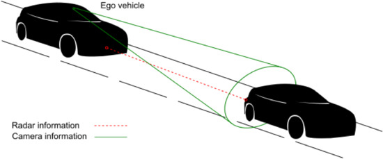
Figure 1.
Concept of using camera feed in addition to radar feed in adaptive cruise control.
This article is structured as follows. Next, a state-of-the-art review is given of the most related scientific research. Then, the utilized dataset and the constructed hardware and software are described in the methods section, which is followed by a description of the experiments. Experimental results are demonstrated which highlight the accuracy of the proposed brake light detector on the gathered dataset. Finally, discussion regarding the impact of the acquired results is presented.
2. State-of-the-Art
The aspect of passenger comfort in passenger vehicles has previously garnered significant research interest. This research indicates that multi-directional acceleration affects the passenger’s trust and comfort levels, but the longitudinal deceleration is more commonly measured and studied in braking situations. Studies have focused on passenger comfort and anticipated feelings of safety in the existence of ADAS systems [7,8,9,10]. Traditionally, roughly 0.2 g has been considered a critical comfort limit for longitudinal deceleration; anything above the limit is beyond the comfort zone [7]. More recent studies have considered even lower deceleration values to be uncomfortable for passengers [10]. In a study conducted by Hoberock, a passenger tolerance was assessed for longitudinal acceleration and jerk [7]. The study included 11 different cases, including subjective questionnaires as well as objectively measured comfort related parameters. Although there was no conclusive statement, due to a wide variation between the studies and the form of results, it could be seen that normal braking fallings in the range of 0.11–0.15 g would be considered acceptable. Wu et al. [8] proposed a comfort-based vehicle-following model. The model considers the comfort aspect by measuring the acceleration to which the passenger is exposed, thus using comfort as control input in the longitudinal deceleration. The results showed that the model is effective and practical for real-world longitudinal deceleration control without sacrificing comfort. Jamson et al. [9] studied the impact of a secondary task uptake, such as watching a DVD while driving, in highly-automated vehicle control. The study was performed with 49 driver participants in a simulation environment, each session lasting for 2 h. The conclusion of the study was that automation improves safety margins associated with vehicle following, drivers are more drawn to secondary tasks while the automation levels increase. However, the study also demonstrated that driver fatigue increases with automation. These studies highlight that automated driving tasks are welcomed and that especially control-related tasks need to consider comfort in the design.
The importance of considering passenger comfort will further increase in the coming years as partially automated and autonomous vehicles become more common. In this study, brake light detection is realized by a three-stage process involving object detection, image preprocessing, and random forest classification. In further studies, brake light detection will then be used to improve passenger comfort by enabling early braking. This is to ameliorate radar-based ACC by fusing visual information about vehicles braking in front. To the best of the authors’ knowledge, no scientific publications regarding this approach exist. However, it is uncertain which technologies are currently being tested and implemented by vehicle manufacturers.
The usage of radar in ADAS systems and, more specifically, in measuring the distance to the vehicle driving directly ahead is well established in the industry and researched in academia. Patole et al. [11] focused on the various developmental approaches to radar data processing. In addition, the authors discussed estimation techniques and radar waveform characterization. According to the authors’ prognosis, fusing radar data with camera vision, lidar, and other sensors will be more common in the future, as such systems have delivered promising results [12]. In a recent simulation study by Kamal et al. [13], a look-ahead scheme of ACC was introduced, predicting the future position and speed of the preceding vehicle by utilizing a conditional persistence prediction technique. The study shows that anticipatory behavior of the ACC could improve the overall driving performance and comfort in high-speed driving.
Previous brake light detection research with machine vision can be divided into nighttime studies [14,15,16,17] and daytime studies [18,19,20]. During the nighttime, the task of brake light detection becomes simpler, due to the vehicle lights already being clearly discernible against a dark background. This is demonstrated in the work of O’Malley et al. [15] who used an HSV filter for detecting vehicle tail-lights, reaching a notable accuracy of 97% in detecting brake lights. Following a similar methodology, Thammakaroon and Tangamchit [14] developed a system that detected brake lights in the darkness with a simplistic RGB model. They used a test sample of 45 images and managed to classify brake light status with 87% accuracy. Chen [16] used a light distribution based Nakagami-distribution model and achieved an average detection accuracy of 76%, with extensive testing in urban and highway routes, as well as under different weather conditions.
During the daytime, simple colorspace filtering is inadequate for detecting the vehicle lights due to the limited contrast of brake lights in regards to image background. Thus, daytime brake light detection is typically performed in such a way that a vehicle is first detected and marked with a bounding box and then the bounding boxes are extracted from the full image to limit the processed image area. The bounding box area has commonly been determined by utilizing the well-established histogram of oriented gradients (HOG) detection algorithm [21]. More modern deep learning-based approaches applicable for vehicle detection include YOLOv3 [5], SSD [22], or RCNN [23]. The latest methods include the detection of small vehicles with ASPP-CenterNet [24]. After extracting the vehicle bounding boxes, the brake light status in each vehicle bounding box is classified. The classification has typically been accomplished with machine learning classifiers, such as convolutional neural networks (CNNs), or colorspace filtering. Common colorspaces for filtering include CIELAB (L*a*b), YCbCR, and hue saturation value (HSV) [25].
The brake light detection framework of Chen et al. [18] utilized HOG to capture the vehicle bounding boxes. They identified lower two tail light candidate regions from these bounding boxes as radially symmetric areas that were found on a common horizontal plane. In other words, the two brake lights should exist as a pair symmetric with respect to the vehicle center line. These regions were filtered with an L*a*b filter. The brake light status was then detected based on high red chromaticity difference to the tail light region, as the lights only occupy some of the tail light region. Their approach yielded an accuracy of 87.6% on their own non-public dataset.
Wang et al. [19] have proposed another brake light detection algorithm based on extracting vehicle rears utilizing a HOG detector. They modified the original HOG detector to better suit the purpose of using road- and vehicle-specific information. The brake light status of a vehicle was evaluated using a CNN classifier, which was trained with images of vehicles with brake lights either on or off. Their classifier achieved an average accuracy of 89% with ten-fold cross-validation on their self-gathered non-public data.
Cui et al. [20] studied tail light detection and signal recognition including turn signals. Their approach included bounding box extraction, a preprocessing stage in HSV colorspace, and signal classification. Bounding box extraction was based on HOG, a pairing algorithm, as well as a support vector machine. The preprocessing stage included HSV colorspace, clustering, and the orientation and location of taillight pairs inside the bounding box. A dictionary learning algorithm was used for the classification stage. The study primarily focused on closely located vehicles, i.e., 5–40 m.
Despite earlier research in the field of brake light detection, not a single available open source implementation exists. Moreover, previous daytime studies have focused on detecting brake lights from clear pictures captured of vehicles close to the research vehicle, in high traffic situations, mostly at a standstill. The detection method presented here is designed to detect the brake lights of moving vehicles at distances ranging from 5 m to 150 m. The approach is benchmarked, and proven to function in a multitude of scenarios, accurately performing at far distances. The presented approach is designed to be used in all daytime weather conditions, yet it also has drawbacks common to camera-based systems, such as lens flares caused by direct sunlight. The proposed algorithm and the gathered dataset will be published in an online repository to facilitate further research on the topic.
3. Methods
3.1. Dataset
A self-gathered dataset was used to test and validate the brake light detection algorithm. Detailed specification of the videos used for constructing the dataset can be seen in Table 1. The equipment used to gather the dataset is introduced in detail in the next section. The dataset was recorded during multiple days at different times, thus including variations in weather conditions such as rain, clear sky, cloudy sky, and indirect sunlight. The recording took place in real traffic conditions in Helsinki metropolitan area during February and March 2020, and the real traffic conditions made it possible to collect data from different distances, mostly over 50 m. Longer distances were emphasized due to the intended application of predictive braking. The dataset includes image material of vehicle rears with brake lights on or off. The recorded dataset captured during this study will be publicly available after the publication. Therefore, this dataset can be used for algorithm training and testing operations in the future.

Table 1.
Detailed specification for the test videos.
The developed algorithm was trained and tested with images from the recorded dataset. The images were manually labeled and separated with a classical split of 80/20% into a train set and test set as can be seen in Table 2. The vehicles in the images have three brake lights in a triangular formation (two on the sides and one in the top middle). The images in which the brake lights were active were labeled as “on”. The aim of the study was to train a random forest algorithm to identify a triangular formation of filtered colorspace information in order to exclude scattered light, other light sources, and disturbances. Later, it will be shown that training the random forest algorithm with the dataset leads to a mask of weights with a triangular formation, emphasizing any light in those areas and attenuating light sources outside those areas.
Table 2.
Images in the dataset.
3.2. Hardware
The algorithm setup used has three main requirements from the hardware: a high definition (HD) camera, narrow angle optics, and suitable computational power. The HD camera was chosen to have a USB interface for ease of use and to minimize installation and setup related errors. The computer has a powerful graphical processing unit (GPU), which is required to run the YOLOv3 algorithm without slowing down a 30-frames-per-second HD-video stream.
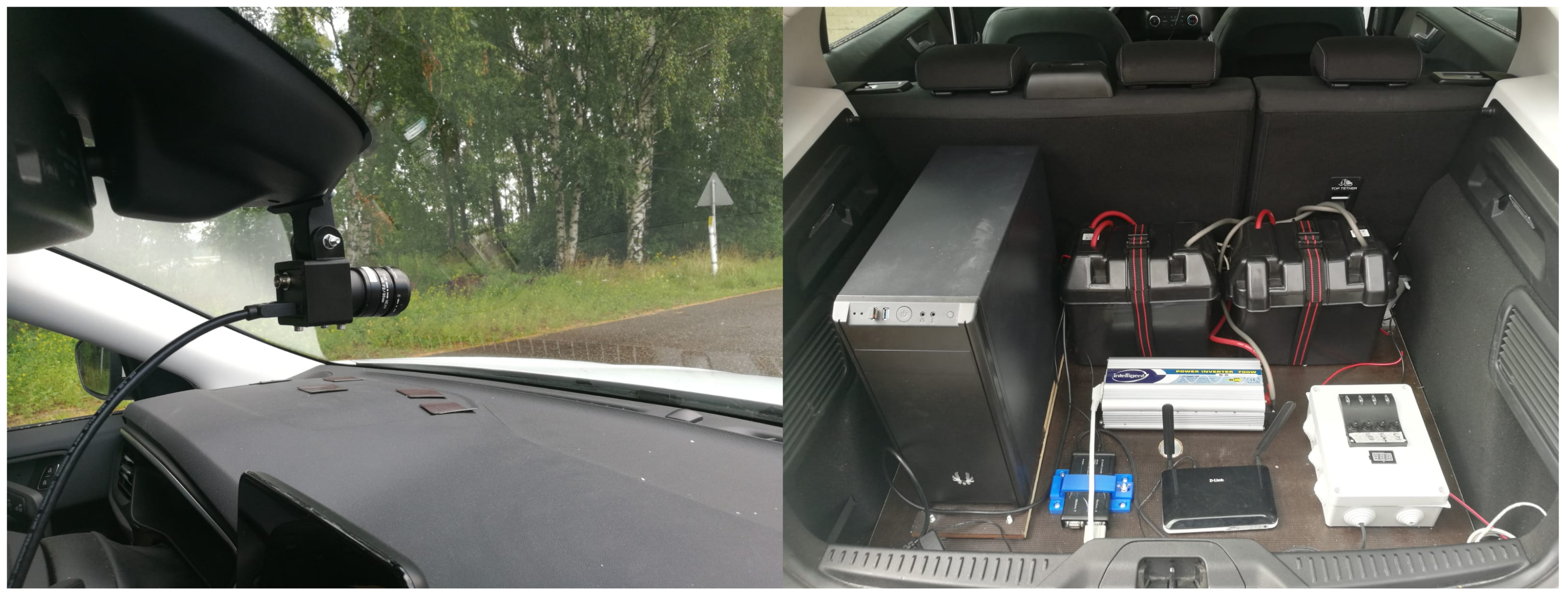
The camera was mounted under the original camera of the vehicle on the rear-view mirror casing in the windshield as seen in Figure 2. This location ensures similar frontal view that the original camera obtains and enables retrofitting the brake light detection system in the vehicle. In the current study, the original camera in the vehicle could not be used. The original camera on the vehicle could be a suitable solution if proper optics were in place. However, access to the original camera feed was not possible. Due to the lack of this type of access to the cameras and control units installed in the vehicle, it was necessary to build a measurement system parallel to the original one. Detailed specifications for the PC and camera can be seen in Table 3. A machine vision grade camera was installed to ensure high resolution video/frame quality and for better overall performance.
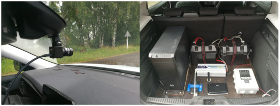
Figure 2.
Hardware installations on the test vehicle. The windshield camera installation on the (left) and computational power with accessories on the (right).
Table 3.
Detailed hardware specification.
3.3. Algorithm
The developed brake light detection algorithm builds upon a YOLOv3 [5] CNN model implemented in PyTorch [28], open source computer vision library OpenCV 3.4.0 [29] and a random forest classification algorithm [30,31].
The used version of YOLOv3 has been trained on the COCO dataset [32] which contains nearly 100,000 samples of passenger vehicles. The detailed training parameters of the network can be found in the original source code [33]. A 608 pixel frame input, which is relatively high for CNN processing, was selected for YOLOv3 to achieve the highest possible detection rates. High input resolution ensures that vehicles can be detected from a longer distance while preserving details in the detected vehicle. Distances up to 150 m are considered here. After detecting the vehicle rears with YOLOv3, the bounding boxes are preprocessed, which means performing colorspace filtering. These preprocessed images are downscaled in resolution and fed to the random forest algorithm. Resolution reduction is necessary to prevent overfitting of the random forest algorithm. However, proper resolution reduction is only possible when the original image is clear. In this case, the clarity is ensured by the high resolution.
Predicting the brake light status of the preceding vehicle from all three brake lights, including upper middle brake light, requires that the rear of the vehicle is properly detected. The developed algorithm assumes that all the vehicles have a center brake light as well as no faulty equipment or malfunctions, such as brake light operation failure or faulty lamps.
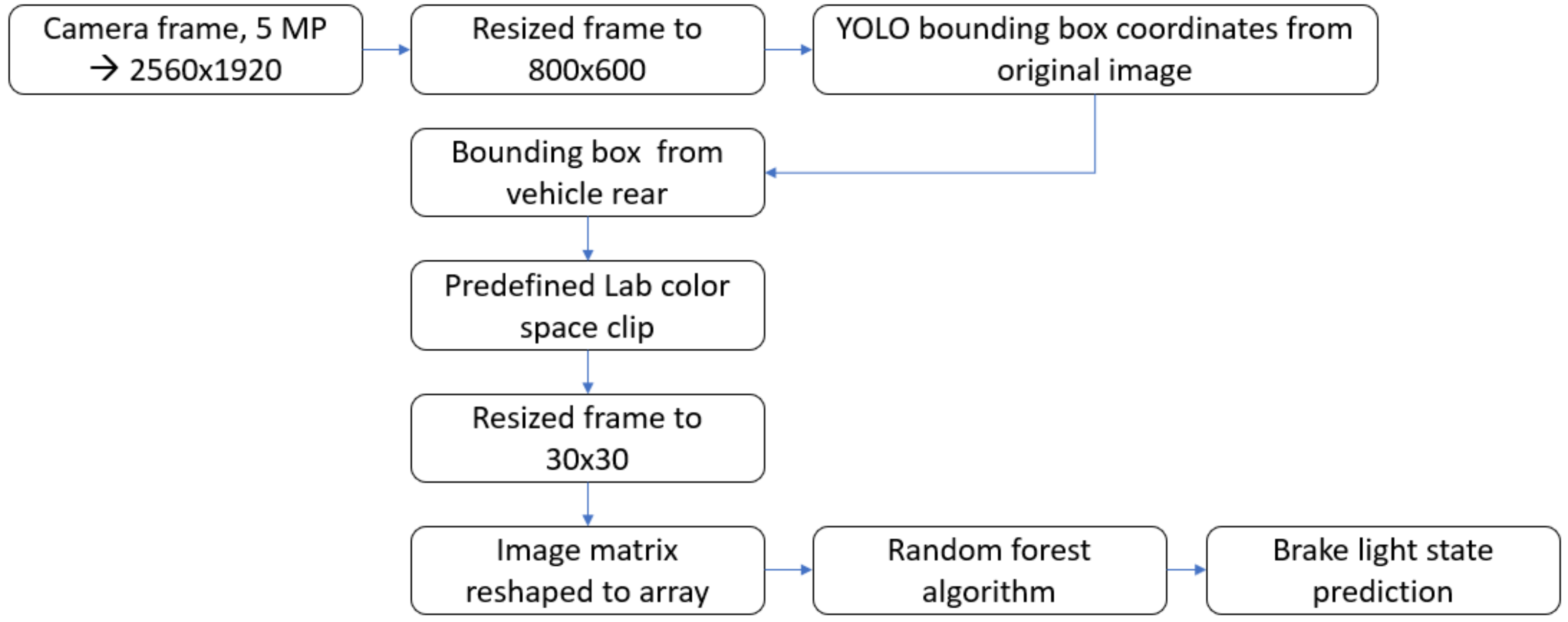
The entire detection process is depicted in Figure 3. For clarity, the detection process can be divided to three stages: (i) object detection, (ii) image preprocessing, and (iii) random forest classification. In Stage (i), the image is processed through the YOLOv3 object detection for vehicle recognition. YOLOv3 object detection returns bounding boxes indicating the areas that have vehicles in the image. The bounding boxes extracted from the original image are then fed into the image preprocessing stage.
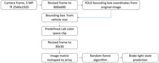
Figure 3.
Workflow for the algorithm.
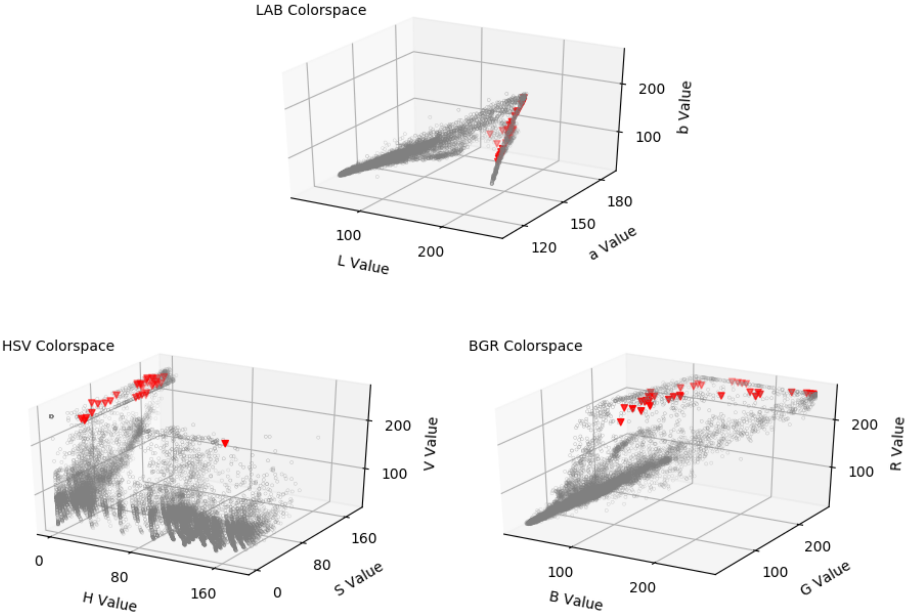
For the colorspace filtering in the preprocessing stage, L*a*b colorspace was used. This colorspace was chosen after observing the LAB, HSV, and RGB values of the brake lights in the gathered dataset. LAB produced the most consistent and separable values for the brake lights. Figure 4 provides a pixel distribution of lit brake lights (marked as red triangles) in comparison to vehicle rear (marked as gray dots). By examining the plot representing an example of the dataset, it can be seen that L*a*b colorspace pixels provide a compact volume in lit brake light pixels. The same distribution was seen in the dataset pixel value scatter and distribution.
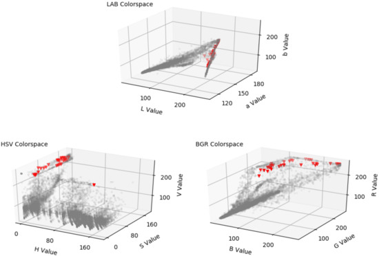
Figure 4.
Scatter plot represents individual pixel values in LAB, HSV, and BGR colorspaces. Red triangles represent the brake light color values when lit, and gray circles represent full image value distribution.
In the L*a*b colorspace, pixels are represented by three variables: L, a, and b. L is the value for lightness, a the green-to-red spectrum, and b the blue-to-yellow spectrum. The L*a*b colorspace was defined by the International Commission on Illumination (CIE) in 1976 and it is officially called the CIELAB colorspace.
Stage (ii) receives bounding box images from Stage (i) and filters away pixel values that do not belong to a pre-specified threshold range. The threshold ranges are defined for all three variables (L, a, b) as shown in Table 4. These threshold ranges were acquired by capturing initial image samples of brake lights and analyzing the color values found in the brake light area at different ranges with different vehicles with the research vehicle camera. Pixels that do not have all their (L, a, b) values in the specified ranges have their values changed to 0. These preprocessed images are used as input for the random forest algorithm in Stage (iii). The purpose of defining the threshold ranges and sending only (L, a, b) within those thresholds is to help the random forest algorithm to respond to those colors that are present in brake lights while they are lit.
Table 4.
Threshold values for the L*a*b colorspace.
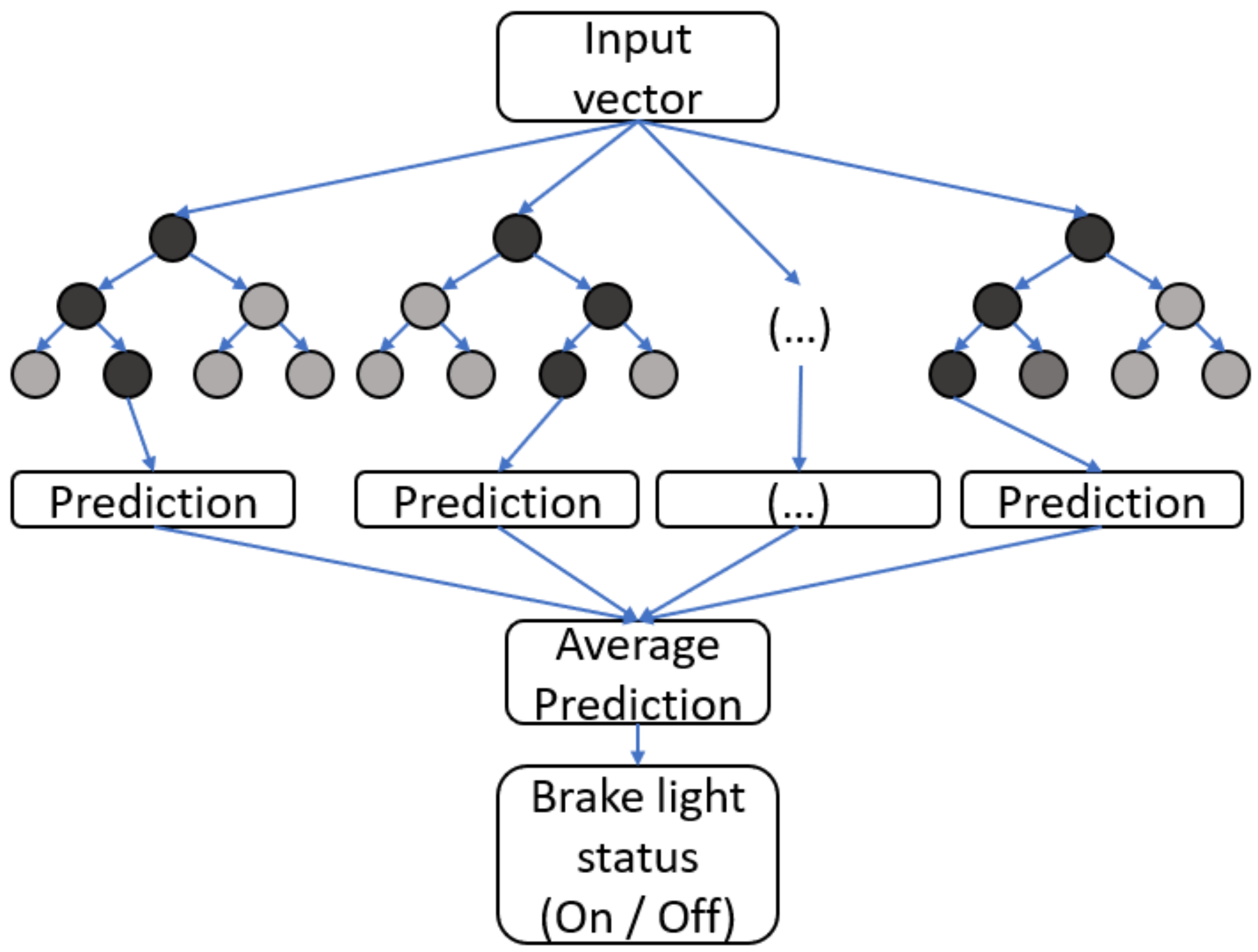
In Stage (iii), the random forest algorithm (Figure 5) must classify whether the brake lights are on or off. The random forest algorithm is an ensemble of decision trees which have been trained on the image dataset. A hundred decision trees were included in the forest in the conducted tests. The image preprocessed earlier is resized into a pixel size of 30 × 30. The 30 × 30 image is then transformed into an input vector including all the three variables (L, a, b) with a length of 2700 elements. This input vector is fed into the random forest classifier. The classification was chosen to be positive if the confidence value returned by the random forest surpassed 0.6. A confidence level of 0.6 was chosen as a suitable value, after practically evaluating the algorithm performance on videos captured from traffic. The 0.6 confidence level increases the robustness of the classification, while still upholding reliable classification in actual braking scenarios. This is somewhat higher than the intuitively selected confidence level of 0.5.
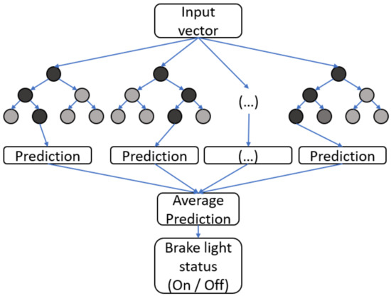
Figure 5.
Workflow for the random forest classifier.
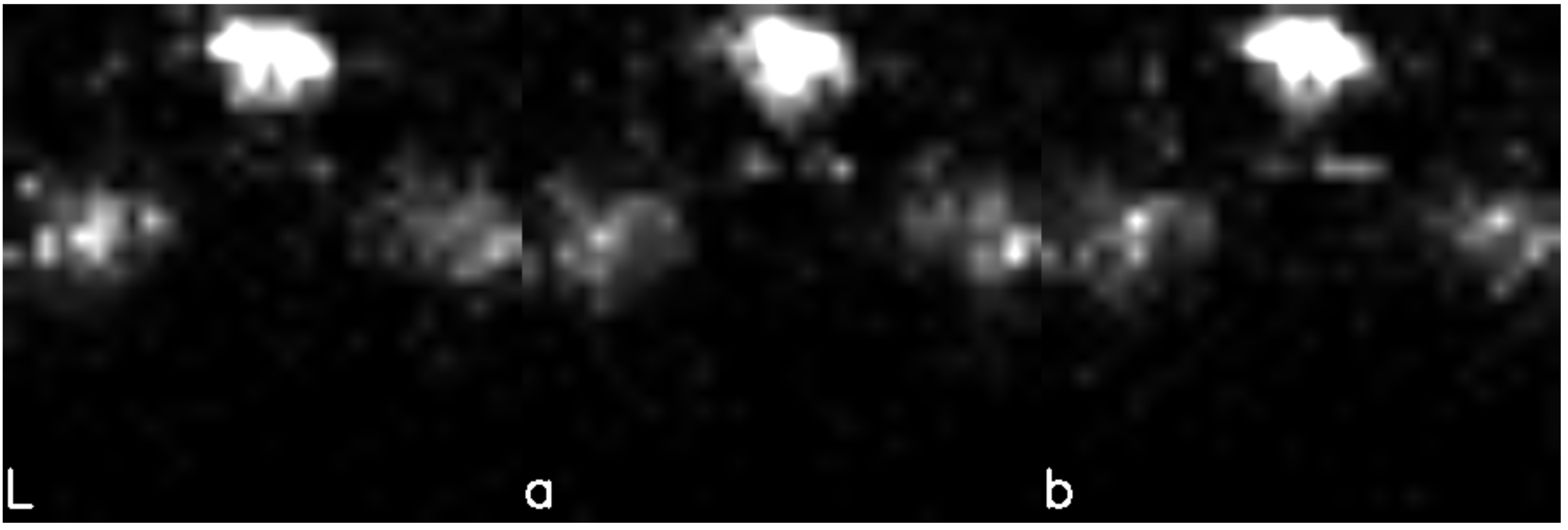
Figure 6 shows the mask visualizing the relative importance of the individual variables, based on the weights learned by the random forest algorithm (the color white being important, black being less so). From these weights, one can observe the process through which the algorithm chooses to report a positive. It searches for high pixel values in the learned areas in each channel. In the presented application of brake light detection, L gives an overall light, a gives red, and b gives yellow. It should be noted that the mask in the figure is a visualization of the training result brought back to image format; the random forest algorithm has the mask information in its own input vector format. In the algorithm, the lights in triangular formation are amplified, whereas a light in a random location would be excluded or attenuated. This approach allowed attenuation of light sources, such as sunlight, scattered light, or oncoming vehicle headlights. The mask can also be viewed as a probability distribution indicating the degree to which each pixel value affects the prediction whether the brake lights are on or off.
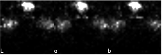
Figure 6.
Visualization of the learned weights in image format (white color important, black less important).
3.4. Experiments
All the camera feed was captured using Spinnaker Python API. The captured raw video format had to be converted into AVI for an OpenCV suitable format. The collected image data was acquired by extracting the bounding boxes placed by YOLOv3. As the bounding box sizes varied, the vehicle rear image sizes also varied. This image data of vehicle rears was used to quantify the classification accuracy of the proposed brake light detection algorithm.
In order to locate the feasible operation range of the algorithm, a test setup was created with two vehicles. The test setup consists of traffic cones placed on the side of a road. The cones were placed with 25 m spacing from 0 to 150 m, resulting in 6 different measurement points. All the cones were placed using a laser distance measurement to achieve accurate distances. Two vehicles were utilized for the experiments. The vehicle with brake light detection was in a standstill at 0 m and the vehicle to be detected was placed with 25 m increments all the way up to 150 m. A video of each position was captured, ensuring that each increment includes a video with brake lights on and off.
4. Results
For evaluation of the performance and suitability of the proposed algorithm for the classification task, presented results include the acquired detection accuracies and a comparison to an approach without the preprocessing step in Stage (ii). This alternative approach skips the colorspace filtering, and performs classification on the raw bounding box images. A confusion matrix is presented to compare the classification results acquired with both approaches. Additionally, an experimental range evaluation was performed with a test vehicle all the way up to 150 m in distance.
4.1. Accuracies
The random forest algorithm was trained based on the images in the dataset. To show the benefits of the preprocessing stage, detection accuracies were compared with preprocessed images and raw images as the input for the random forest algorithm. All the reported accuracies are the average results of 15 full training iterations, meaning that the algorithm was fully trained 15 times and the average accuracy was calculated over the individual classification results on the test set. On average, the algorithm classified an image in 6.6 ms, whereas the YOLOv3 bounding box extraction required 28 ms. The result is from the dataset test set including 152 pictures. Evaluating the algorithm with the preprocessing stage led to an accuracy of 81.8%. The corresponding accuracy without preprocessing was 73.4%. These average accuracies can be seen in Table 5 as well as minimum and maximum over 15 training iterations. Min and max values were reported to show that the algorithm behavior is robust and consistent. Accuracies with preprocessing were found superior to those achieved with raw images.
Table 5.
Accuracies for the comparison.
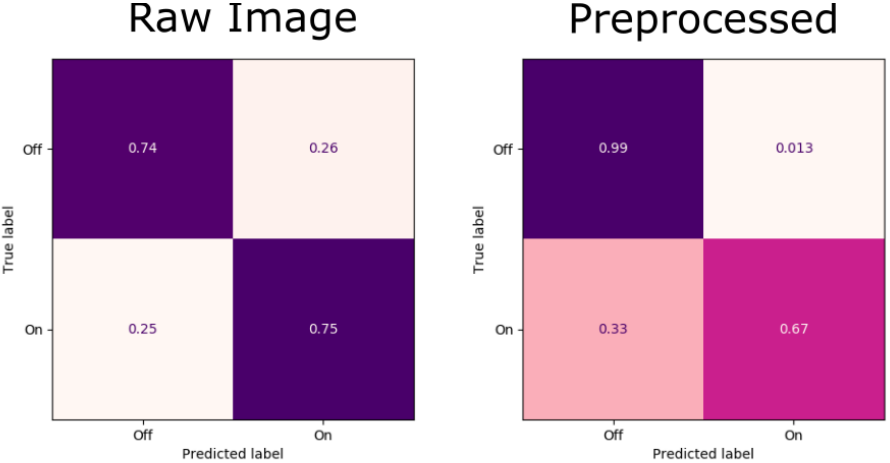
The acquired confusion matrices are shown in Figure 7, with the confusion matrix from the raw image classifier shown on the left, and the confusion matrix from the classifier with preprocessing shown on the right. In the reported confusion matrices, top left and lower right mean correct perception. The lower left and top right show false negative and false positive perceptions, respectively. The result shows that the algorithm with preprocessing performs well, although indicating a small bias towards false negatives. Nevertheless, the overall accuracy achieved with preprocessing is still higher. Direct comparison of the presented algorithm to other state-of-the-art algorithms would be beneficial, yet unfortunately the source codes of relevant algorithms are not available. However, Table 6 presents main operation conditions and key parameters of each study respectfully. Results are presented from each study and compared to the result achieved in this study. Unambiguous comparison of the accuracies is difficult, as each study has utilized different datasets, specific hardware, different weather conditions, and distances to the vehicles in front.

Figure 7.
Normalized confusion matrices from the random forest algorithm.
Table 6.
Comparison of the brake light detection algorithms.
4.2. Range Test
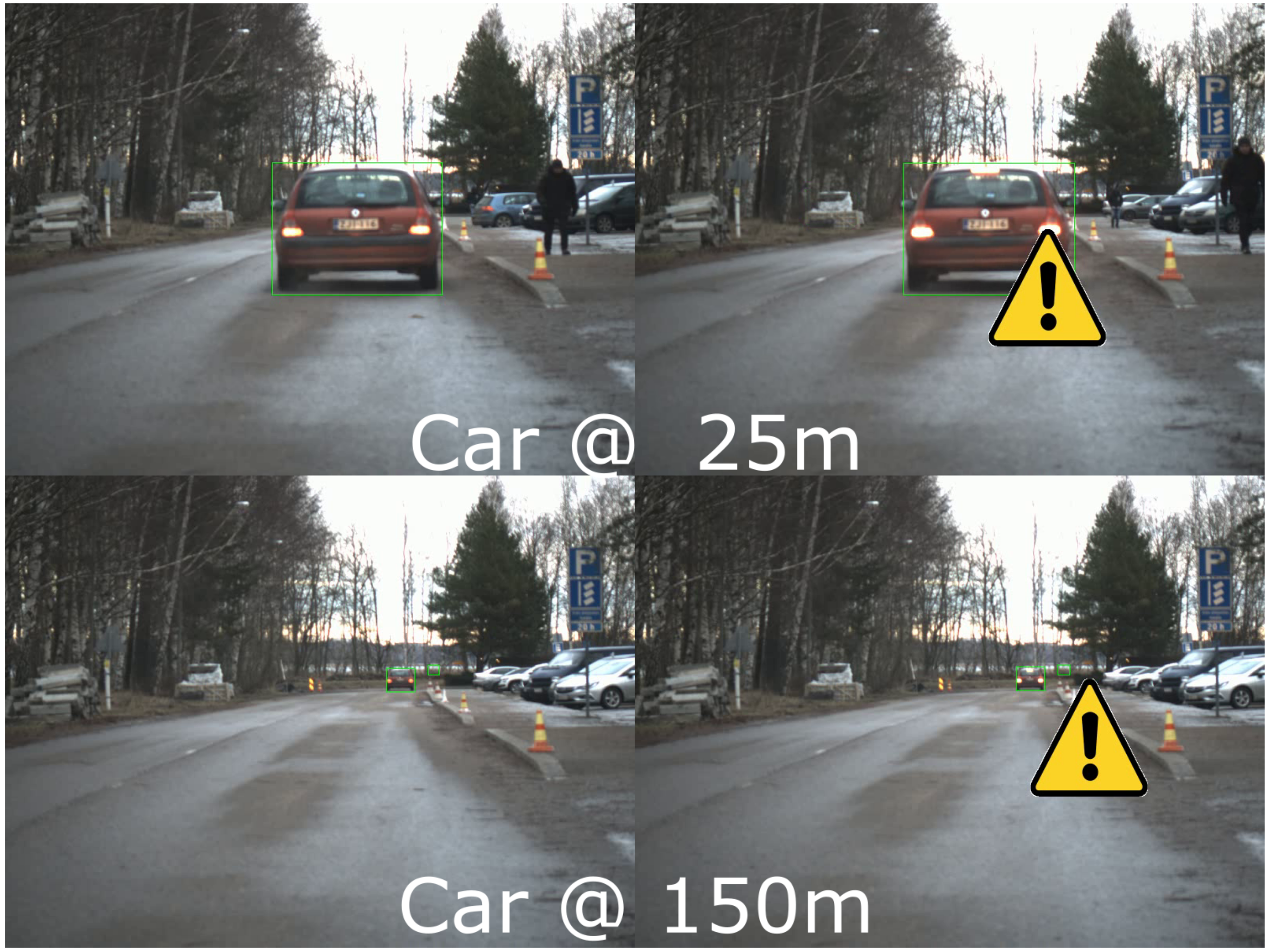
To analyze the applicability in a real-world use case, a range test with two vehicles was performed at 25 m intervals from 25 m to 150 m. The algorithm with preprocessing performed with a high accuracy in standstill situations, recognizing brake light occasions at every 25 m point all the way up to 150 m. An example of the recognition can be seen in both extremes in Figure 8. A brake light detection occurrence is displayed with a yellow triangle featuring an exclamation mark.
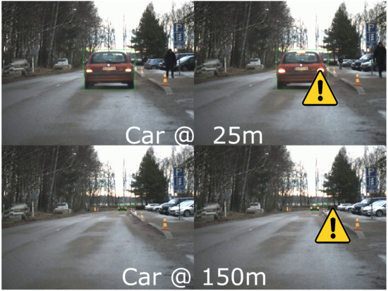
Figure 8.
Range test with preprocessing at 25 m and 150 m, warning triangle indicating detected brake lights.
4.3. Algorithm Output
Additional video material was captured for analysis from the Helsinki metropolitan area, mostly driving on two specific main roads during intensive traffic or congestion. Based on this experimental test with video material, the proposed method shows promising results on detecting brake lights in video material. It is shown in Figure 9 in Pictures (a)–(d) that brake lights were detected well. Interestingly, even on a rainy day the algorithm performed well as shown in Picture (b). Examples of false predictions are shown in the second row in Pictures (e)–(h). The most notable cause of false predictions was capturing vehicle bounding boxes that did not actually contain vehicle rears.
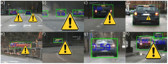
Figure 9.
Example of the algorithm output. Upper row shows successful detections, and lower row unsuccessful detections. Respective confidence values in the collage from left to right: (a) 0.98 and 0.9, (b) 0.9, (c) 0.95, (d) 0.97, (e) 0.53, (f) 0.7, (g) 0.59, and (h) 0.86.
5. Discussion
5.1. Algorithm Performance
As seen in the results, the developed algorithm performs well in detecting lit brake lights when tested with the images from the dataset as well as with test video material. The overall performance of the algorithm on the utilized challenging and extensive dataset is close to those of previous daytime brake detection studies [18,19]. However, a direct comparison to previous algorithms is not productive due to usage of different datasets. The dataset utilized here features vehicles at considerable distances of up to 150 m, thus differentiating the contributions of this paper from previous studies which focused on vehicles at shorter distances. The lack of an open dataset for benchmarking brake light detection algorithms has been acknowledged in the literature [19], and the dataset used here will be published to allow for accurate future benchmarking.
Due to the aim of the use case to improve ride comfort, the algorithm was designed to include a bias towards false negatives. In practice, the algorithm did not detect all the braking events. Nevertheless, the algorithm hardly produced any false positives, indicating that it would be extremely rare for predictive braking to be unnecessarily engaged. This behavior was here considered beneficial, because the brake light detection algorithm was aimed at complementing the radar readings in the decision-making process. False negatives from the camera are eventually corrected by the radar, only leading to an occasional slightly more steep braking operation. Still, the reliable true positives complement the braking decision making, resulting in more frequent comfortable decelerations.
5.2. Applicability in Industrial Applications
The factory-installed camera setup of the vehicle could be used with proper optics. In this study, the camera and optics were installed parallel to the existing vehicle multi-purpose camera to ensure effortless access to a video feed of the road ahead. Most of the vehicle manufacturers use high-quality multipurpose cameras for road lane recognition and other fairly demanding partially, automated tasks, so the camera quality should be sufficient for this type of system as well. The computation power of the vehicle and factory installed control units could turn out to be a bottleneck for the algorithm task. In order for the algorithm to work with live video-feed from the camera, a substantial amount of computation power is required. The classification solution proposed here is lightweight but suffers from the object detection part, which should be replaced to reduce the computational power requirements while maintaining a good performance. Regarding the applicability of the developed algorithm in production grade systems, the algorithm has the benefit of not requiring an excessive amount of data for training. The colorspace threshold values are camera-dependent, meaning that the values must be adjusted when a different camera is used. Nevertheless, as shown in this paper, these threshold values and the random forest classifier training can be achieved with a few hundred images. Considering many other machine vision and machine learning applications, this amount of data is fairly modest for achieving a functional detection system.
5.3. Future Improvements to the Algorithm
While conducting the experimental tests, it was noted that the algorithm suffered from some issues common to most machine vision algorithms, such as glares and reflections caused by sunlight. Future tests could include more sunny data with the sun being at different heights. The angle of the sun affects the glares and reflections captured by the camera, thus it could affect the accuracy of the algorithm. Nevertheless, it was noticed that the presented approach was rather robust towards rain. Raindrops on the windshield or light fog did not noticeably impact the performance of the algorithm. More application-specific issues in the tests included detected vehicles that were sideways, and different types of emergency vehicles that significantly differ from normal passenger vehicles in appearance. The presented test results highlight that the algorithm featuring the preprocessing displays a bias towards false negatives.
As stated earlier, on some occasions the algorithm reacts to vehicles that are sideways, as seen in Figure 9. These false positives, in the picture marked with (e), occur quite rarely. This type of false identification could be solved by using other methods for vehicle rear detection. When utilizing other methods for vehicle rear recognition, attention should be focused on robust detection rates as well as on a fast algorithm run-time. One option could be a vehicle orientation analysis with a 3D bounding box estimation, separating different sides of the vehicle, thereby relaying only the rear to the brake light algorithm.
The conducted experiments were measured among real traffic on relatively straight roads. Sharp turns or steep inclinations were not featured in the gathered dataset. In all of these cases, the detection can be affected as the vehicle ahead may move out of the region of interest in the camera view. In future research, these types of scenarios could be recognized utilizing sensor data of the steering angle or the vehicle accelerometer. This type of approach would solve such cases to some extent.
6. Conclusions
This paper presented a lightweight algorithm for brake light detection built by combining existing YOLOv3 object detection and scikit-learn random forest classifier implementations. Conducted experiments yielded promising results, delivering a high prediction accuracy even up to distances as far as 150 m. The hybrid approach of colorspace preprocessing and a simple random forest classifier showed a notable improvement when compared to processing with only a random forest classifier. When analyzing the performance of the algorithm, it was remarked that most false readings were caused by light reflections and rapidly changing lighting conditions.
The method presented could be used to improve many other assistance systems in vehicles, such as adaptive cruise control and possibly collision avoidance. In suburban areas, detecting brake lights could be used as a part of brake assist. In both cases, the best result would be achieved with a sensor fusion of camera and radar data.
Future research will include utilizing the communication interface of the research vehicle for tuning the adaptive cruise controller with the output of a real-time implementation of the brake light detection algorithm. The goal is to improve the ACC performance in real world field tests by improving the longitudinal control and more accurately anticipating the preceding vehicle intentions than the current radar-based system installed in the research vehicle. The radar-based ACC can only tell the current speed and heading of the object with limited information about the future intentions of the vehicle. Utilizing machine vision to detect the braking status of the vehicle ahead adds another layer for control, thus potentially rendering the ACC more predictive. The predictive nature in the control system would improve the overall safety and comfort levels of passengers in the vehicle. This type of predictive control system should be equipped in future production vehicles for enhanced passenger satisfaction.
Author Contributions
Conceptualization, J.P., R.O., J.V., K.K. and K.T.; Methodology, J.P. and R.O.; Data curation, J.P., R.O. and J.V.; Investigation, J.P. and R.O.; Formal analysis, J.P., R.O., J.V. and K.K.; Software, J.P. and R.O.; Writing—original draft preparation, J.P. and R.O.; Writing—review and editing, J.P., R.O., J.V., K.K. and K.T.; Visualization, J.P., R.O., J.V. and K.K.; Supervision, K.T.; Project administration, J.P., K.T. and R.O.; and Funding acquisition, K.T. All authors have read and agreed to the published version of the manuscript.
Funding
This research was funded by Henry Ford Foundation Finland, Aalto University and Academy of Finland (Grant Number:326346).
Institutional Review Board Statement
Not applicable.
Informed Consent Statement
Not applicable.
Data Availability Statement
Code used in this study is available at: https://version.aalto.fi/gitlab/pirhonj2/brake-light-project (accessed on 8 March 2022). The recorded dataset used in this study will be publicly available after the publication.
Conflicts of Interest
The authors declare no conflict of interest.
Abbreviations
The following abbreviations are used in this manuscript:
| ACC | Adaptive cruise control |
| ADAS | Advanced driver-assistance systems |
| CA | Collision avoidance |
| LAB | L for lightness, a and b for color components (colorspace) |
| CNN | Convolutional Neural Network |
| GPU | Graphical processing unit |
| HD | High definition |
| HOG | Histogram of oriented gradients |
| HSV | Hue, Saturation, and Value components (colorspace) |
| NDM | Nakagami-distribution model |
| RF | Random Forest |
| RGB | Red, Green and Blue components (colorspace) |
| SVM | Support Vector Machine |
| USB | Universal serial bus |
| YCbCR | Y, CB, and CR for luma and chroma components (colorspace) |
| YOLO | You only look once |
References
- National Highway Traffic Safety Administration. TRAFFIC SAFETY FACTS 2017. 2019. Available online: https://crashstats.nhtsa.dot.gov/Api/Public/ViewPublication/812806 (accessed on 20 November 2019).
- European Road Safety Observatory. Annual Accident Report 2018. 2018. Available online: https://ec.europa.eu/transport/road_safety/sites/roadsafety/files/pdf/statistics/dacota/asr2018.pdf (accessed on 20 November 2019).
- Macioszek, E.; Iwanowicz, D. A Back-of-Queue Model of a Signal-Controlled Intersection Approach Developed Based on Analysis of Vehicle Driver Behavior. Energies 2021, 14, 1204. [Google Scholar] [CrossRef]
- Macioszek, E. Roundabout Entry Capacity Calculation—A Case Study Based on Roundabouts in Tokyo, Japan, and Tokyo Surroundings. Sustainability 2020, 12, 1533. [Google Scholar] [CrossRef] [Green Version]
- Redmon, J.; Farhadi, A. Yolov3: An incremental improvement. arXiv 2018, arXiv:1804.02767. [Google Scholar]
- Breiman, L. Random forests. Mach. Learn. 2001, 45, 5–32. [Google Scholar] [CrossRef] [Green Version]
- Hoberock, L.L. A Survey of Longitudinal Acceleration Comfort Studies in Ground Transportation Vehicles; Technical Report; Council for Advanced Transportation Studies: Austin, TX, USA, 1976. [Google Scholar]
- Wu, Z.; Liu, Y.; Pan, G. A smart car control model for brake comfort based on car following. IEEE Trans. Intell. Transp. Syst. 2008, 10, 42–46. [Google Scholar]
- Jamson, A.H.; Merat, N.; Carsten, O.M.; Lai, F.C. Behavioural changes in drivers experiencing highly-automated vehicle control in varying traffic conditions. Transp. Res. Part C Emerg. Technol. 2013, 30, 116–125. [Google Scholar] [CrossRef] [Green Version]
- Du, Y.; Liu, C.; Li, Y. Velocity control strategies to improve automated vehicle driving comfort. IEEE Intell. Transp. Syst. Mag. 2018, 10, 8–18. [Google Scholar] [CrossRef]
- Patole, S.M.; Torlak, M.; Wang, D.; Ali, M. Automotive radars: A review of signal processing techniques. IEEE Signal Process. Mag. 2017, 34, 22–35. [Google Scholar] [CrossRef]
- Mahlisch, M.; Hering, R.; Ritter, W.; Dietmayer, K. Heterogeneous fusion of Video, LIDAR and ESP data for automotive ACC vehicle tracking. In Proceedings of the 2006 IEEE International Conference on Multisensor Fusion and Integration for Intelligent Systems, Heidelberg, Germany, 3–6 September 2006; pp. 139–144. [Google Scholar]
- Kamal, M.A.S.; Hashikura, K.; Hayakawa, T.; Yamada, K.; Imura, J.i. Adaptive Cruise Control with Look-Ahead Anticipation for Driving on Freeways. Appl. Sci. 2022, 12, 929. [Google Scholar] [CrossRef]
- Thammakaroon, P.; Tangamchit, P. Predictive brake warning at night using taillight characteristic. In Proceedings of the 2009 IEEE International Symposium on Industrial Electronics, Seoul, Korea, 5–8 July 2009; pp. 217–221. [Google Scholar]
- O’Malley, R.; Jones, E.; Glavin, M. Rear-lamp vehicle detection and tracking in low-exposure color video for night conditions. IEEE Trans. Intell. Transp. Syst. 2010, 11, 453–462. [Google Scholar] [CrossRef]
- Chen, D.Y.; Peng, Y.J. Frequency-tuned taillight-based nighttime vehicle braking warning system. IEEE Sens. J. 2012, 12, 3285–3292. [Google Scholar] [CrossRef]
- Chen, D.Y.; Lin, Y.H.; Peng, Y.J. Nighttime brake-light detection by Nakagami imaging. IEEE Trans. Intell. Transp. Syst. 2012, 13, 1627–1637. [Google Scholar] [CrossRef]
- Chen, H.T.; Wu, Y.C.; Hsu, C.C. Daytime preceding vehicle brake light detection using monocular vision. IEEE Sens. J. 2015, 16, 120–131. [Google Scholar] [CrossRef]
- Wang, J.G.; Zhou, L.; Pan, Y.; Lee, S.; Song, Z.; Han, B.S.; Saputra, V.B. Appearance-based brake-lights recognition using deep learning and vehicle detection. In Proceedings of the 2016 IEEE Intelligent Vehicles Symposium (IV), Gothenburg, Sweden, 19–22 June 2016; pp. 815–820. [Google Scholar]
- Cui, Z.; Yang, S.W.; Tsai, H.M. A vision-based hierarchical framework for autonomous front-vehicle taillights detection and signal recognition. In Proceedings of the 2015 IEEE 18th International Conference on Intelligent Transportation Systems, Gran Canaria, Spain, 15–18 September 2015; pp. 931–937. [Google Scholar]
- Dalal, N.; Triggs, B. Histograms of oriented gradients for human detection. In Proceedings of the 2005 IEEE Computer Society Conference on Computer Vision and Pattern Recognition (CVPR’05), San Diego, CA, USA, 20–25 June 2005; Volume 1, pp. 886–893. [Google Scholar]
- Liu, W.; Anguelov, D.; Erhan, D.; Szegedy, C.; Reed, S.; Fu, C.Y.; Berg, A.C. Ssd: Single shot multibox detector. In Proceedings of the European Conference on Computer Vision, Amsterdam, The Netherlands, 11–14 October 2016; pp. 21–37. [Google Scholar]
- Ren, S.; He, K.; Girshick, R.; Sun, J. Faster r-cnn: Towards real-time object detection with region proposal networks. In Proceedings of the Advances in Neural Information Processing Systems 28: Annual Conference on Neural Information Processing Systems 2015, Montreal, QC, Canada, 7–12 December 2015; pp. 91–99. [Google Scholar]
- Li, G.; Xie, H.; Yan, W.; Chang, Y.; Qu, X. Detection of Road Objects With Small Appearance in Images for Autonomous Driving in Various Traffic Situations Using a Deep Learning Based Approach. IEEE Access 2020, 8, 211164–211172. [Google Scholar] [CrossRef]
- Color Space—Wikipedia. 2020. Available online: https://en.wikipedia.org/wiki/Color_space (accessed on 20 October 2020).
- FLIR. Blackfly S USB3. 2020. Available online: https://www.flir.eu/products/blackfly-s-usb3?model=BFS-U3-50S5C-C (accessed on 21 July 2020).
- Thorlabs. C-Mount Format Camera MVL35M23. 2020. Available online: https://www.thorlabs.com/thorproduct.cfm?partnumber=MVL35M23 (accessed on 20 August 2020).
- Paszke, A.; Gross, S.; Massa, F.; Lerer, A.; Bradbury, J.; Chanan, G.; Killeen, T.; Lin, Z.; Gimelshein, N.; Antiga, L.; et al. Pytorch: An imperative style, high-performance deep learning library. In Proceedings of the Advances in Neural Information Processing Systems 32: Annual Conference on Neural Information Processing Systems 2019, Vancouver, BC, Canada, 8–14 December 2019; pp. 8026–8037. [Google Scholar]
- Bradski, G. The OpenCV Library. Dr. Dobb’s J. Softw. Tools 2000, 25, 120–123. [Google Scholar]
- Ho, T.K. Random decision forests. In Proceedings of the 3rd International Conference on Document Analysis and Recognition, Montreal, QC, Canada, 14–16 August 1995; Volume 1, pp. 278–282. [Google Scholar]
- Pedregosa, F.; Varoquaux, G.; Gramfort, A.; Michel, V.; Thirion, B.; Grisel, O.; Blondel, M.; Prettenhofer, P.; Weiss, R.; Dubourg, V.; et al. Scikit-learn: Machine Learning in Python. J. Mach. Learn. Res. 2011, 12, 2825–2830. [Google Scholar]
- Lin, T.Y.; Maire, M.; Belongie, S.; Hays, J.; Perona, P.; Ramanan, D.; Dollár, P.; Zitnick, C.L. Microsoft coco: Common objects in context. In Proceedings of the European Conference on Computer Vision, Zurich, Switzerland, 6–12 September 2014; pp. 740–755. [Google Scholar]
- Redmon, J. Darknet: Open Source Neural Networks in C. 2013–2016. Available online: http://pjreddie.com/darknet/ (accessed on 8 March 2022).


Publisher’s Note: MDPI stays neutral with regard to jurisdictional claims in published maps and institutional affiliations. |
© 2022 by the authors. Licensee MDPI, Basel, Switzerland. This article is an open access article distributed under the terms and conditions of the Creative Commons Attribution (CC BY) license (https://creativecommons.org/licenses/by/4.0/).