An Approach for Modelling Harnesses in the Extreme near Field for Low Frequencies
Abstract
:1. Introduction
2. Near-Field Approximations Very Close to the Dipole Source
2.1. Near Field Representation of Harnesses in the Low-Frequency Domain
2.2. Considerations for Observation Distances Comparable to the Cable’s Length
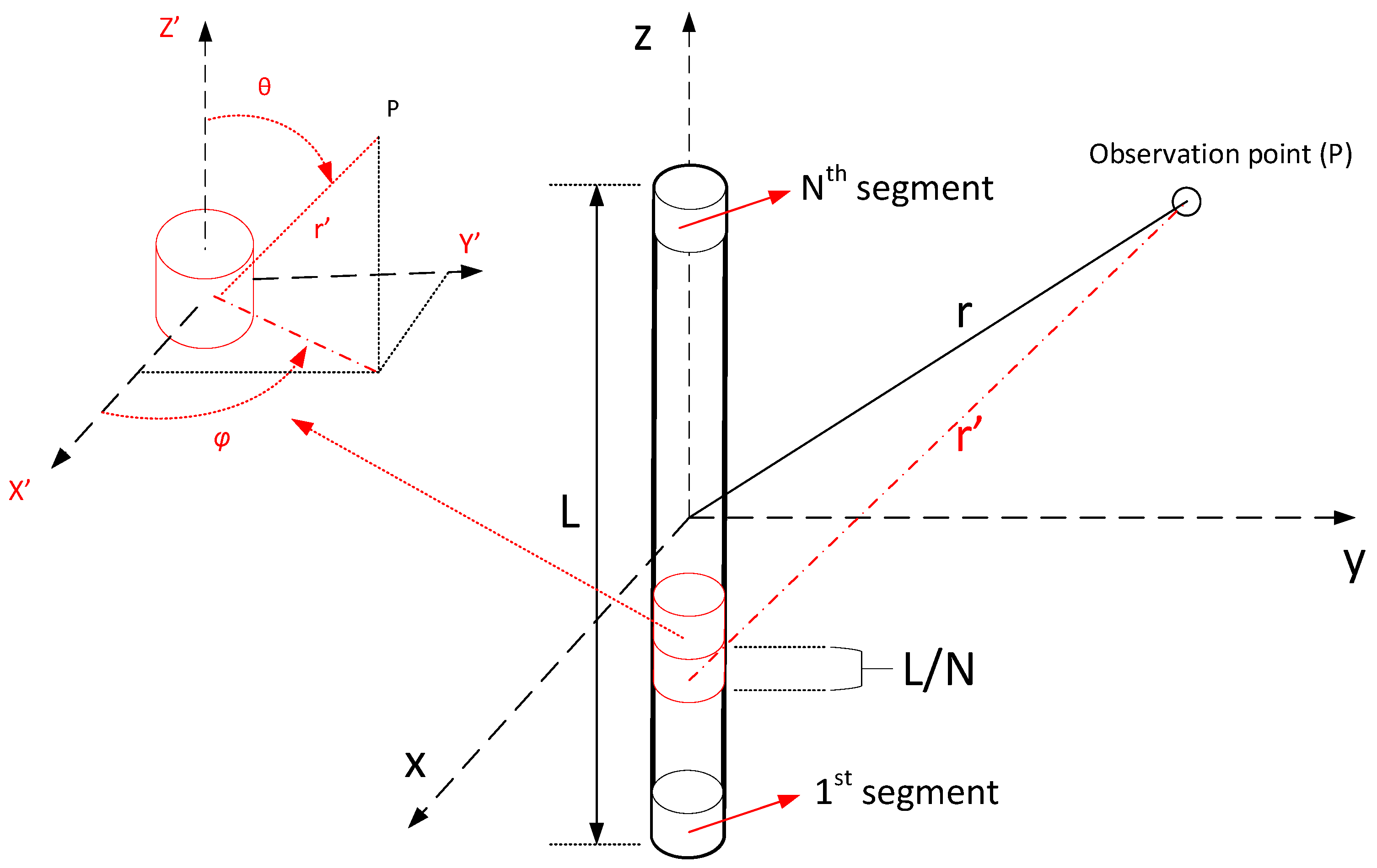
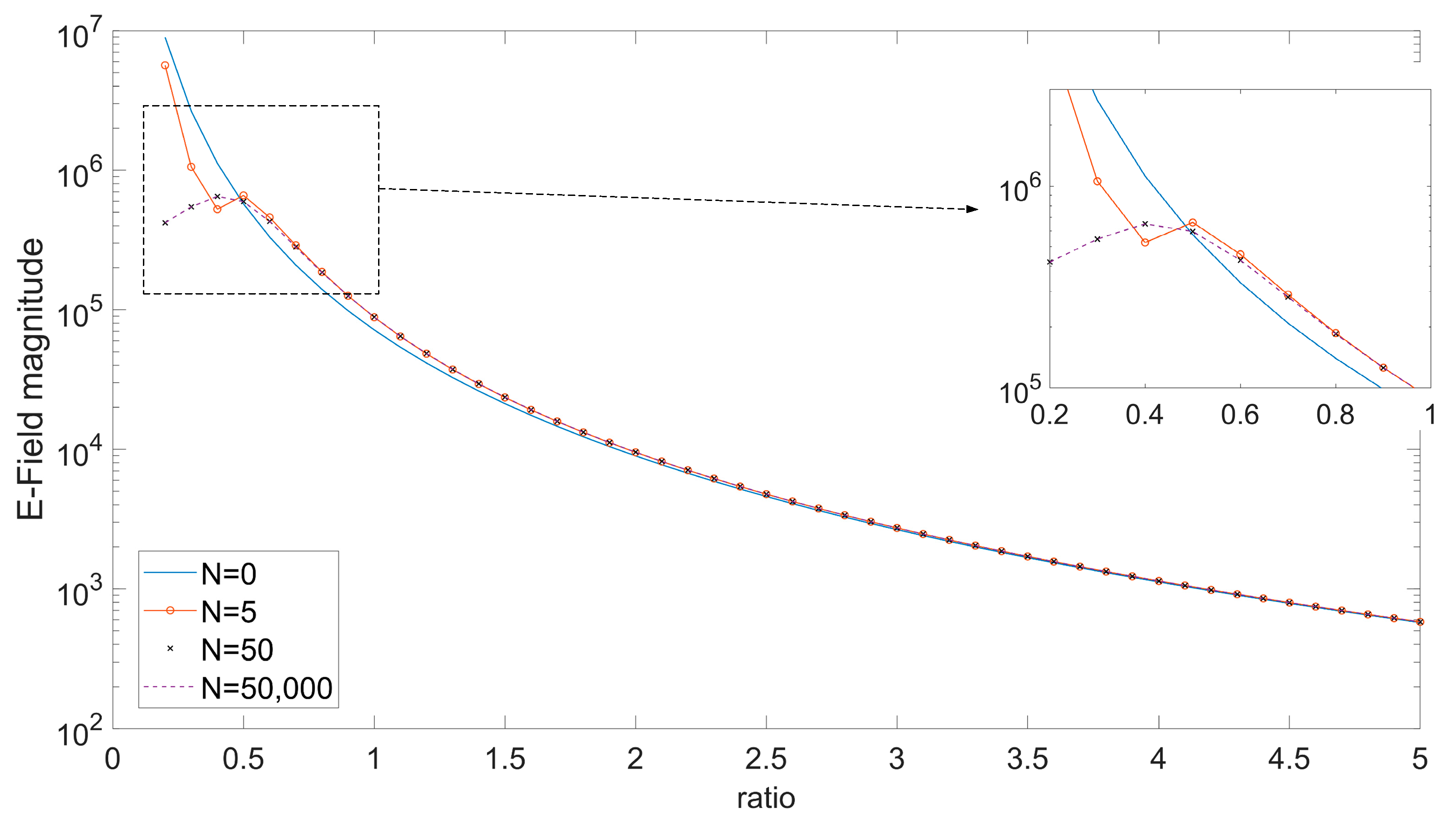
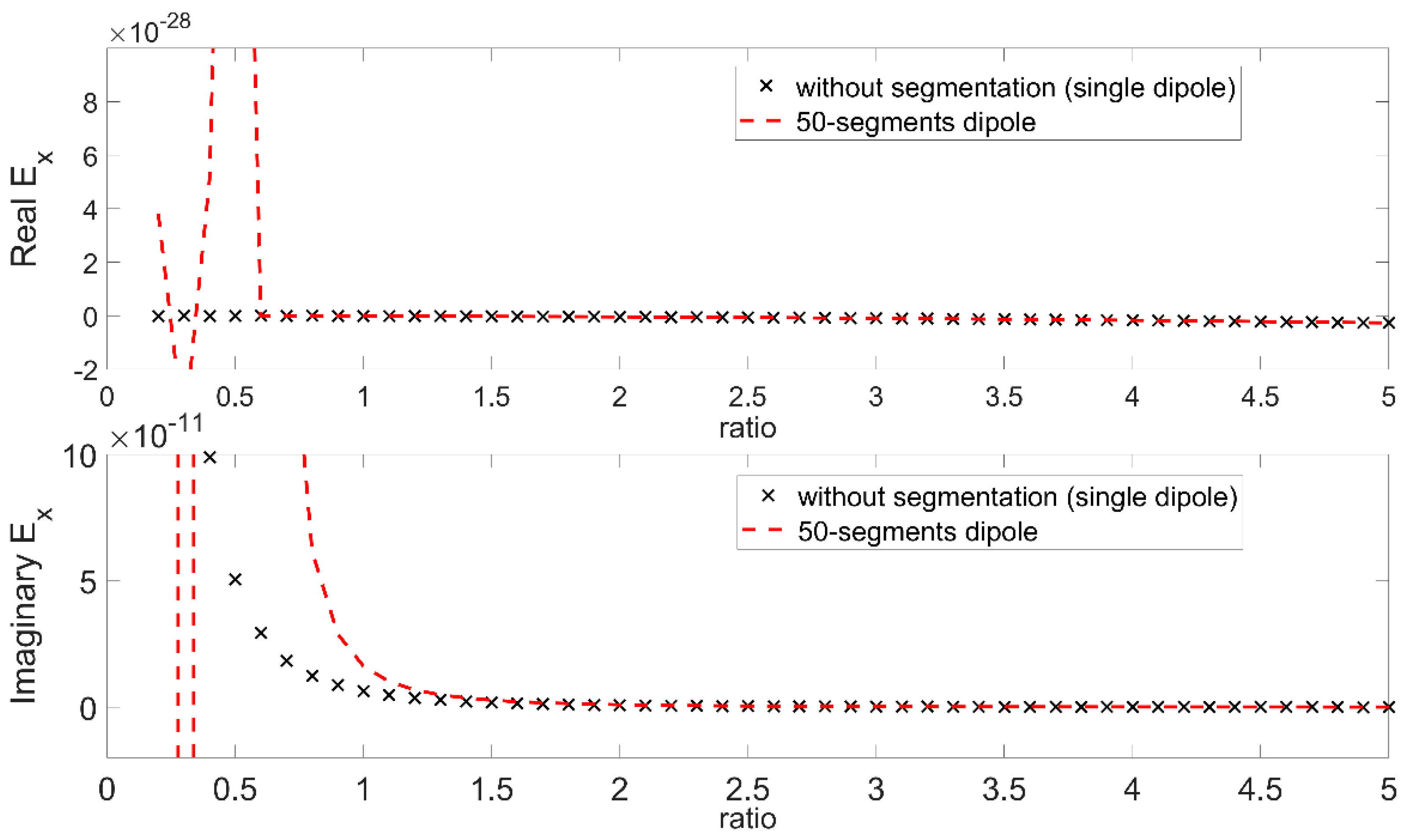
- Single Dipole Case: is when the electric field is evaluated from Equations (1)–(3), considering that the source (cable) is one dipole with length equal to the cable length.
- Segmented Cable Case: is when the electric field is evaluated from the superposition of the electric fields of N segment dipoles, each has a length equal to L/N laying consecutively on the cable path with its center at −L/2 + L/2N + i*L/N (i = 0, …, N − 1), and contributing to the total field with its segment field calculated from (1)–(3).
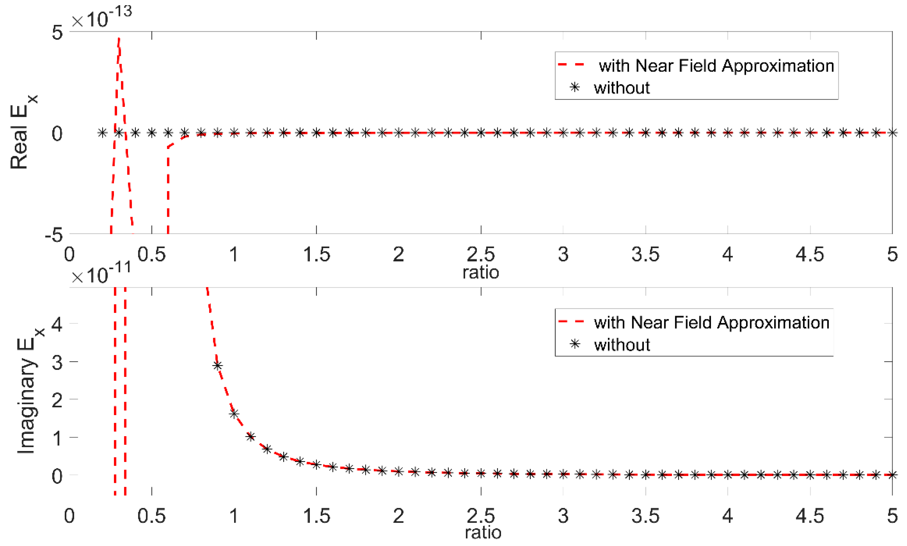
- Single Dipole Case with Near Field Approximation: is when the electric field is evaluated from Equations (4)–(6), considering that the source (cable) is one dipole with length L equal to the cable length.
- Segmented Cable Case with Near Field Approximation: is when the electric field is evaluated from the superposition of the electric fields of N segment dipoles, each having a length equal to L/N, laying consecutively on the cable path with its center at −L/2 + L/2N + i*L/N (i = 0, …, N − 1), and contributing to the total field with its segment field calculated from (4)–(6).
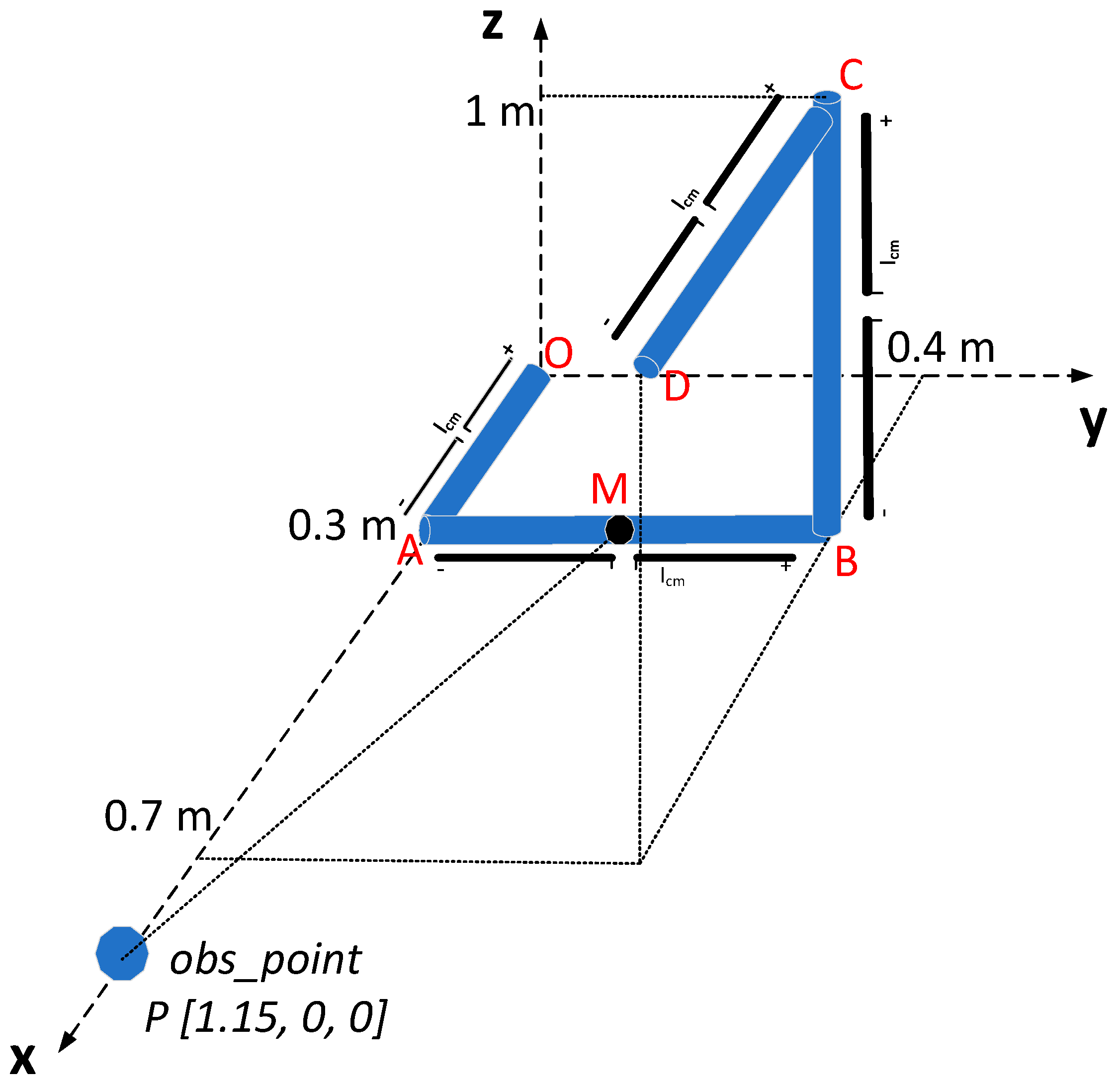
3. Application of the Segmentation Technique in Complex Geometries
- Input (observation point coordinates)
- Input (cable segments start/endpoint coordinates)
- Input (current distribution)
- For i = 1 to number of segments
- Calculate mid-point coordinates for segments i,
- Calculate mid-point—observation point distance
- end
- set reference point coordinates equal to the coordinates of the mid-point with the minimum distance.
- Calculate ratio parameter.
4. Conclusions
Author Contributions
Funding
Data Availability Statement
Conflicts of Interest
References
- Mora, N.; Rachidi, F.; Pelissou, P.; Junge, A. MTL modeling of spacecraft harness cable assemblies. In Proceedings of the 2014 IEEE International Symposium on Electromagnetic Compatibility, Raleigh, NC, USA, 4–8 August 2014; pp. 277–282. [Google Scholar] [CrossRef]
- Arianos, S.; Francavilla, M.A.; Righero, M.; Vipiana, F.; Savi, P.; Bertuol, S.; Ridel, M.; Parmantier, J.-P.; Pisu, L.; Bozzetti, M.; et al. Evaluation of the modeling of an EM illumination on an aircraft cable harness. IEEE Trans. Electromagn. Compat. 2014, 56, 844–853. [Google Scholar] [CrossRef]
- Ridel, M.; Savi, P.; Parmantier, J.-P. Characterization of complex aeronautic harness—Numerical and experimental validations. Electromagnetics 2013, 33, 341–352. [Google Scholar] [CrossRef]
- Michelena, M.D.; Cencerrado, A.A.O.; De Frutos Hernansanz, J.; Rodriguez, M.A. New techniques of magnetic cleanliness for present and near future missions. In Proceedings of the 2019 International Symposium on Electromagnetic Compatibility (EMC Europe 2019), Barcelona, Spain, 2–6 September 2019; pp. 727–730. [Google Scholar] [CrossRef]
- Capsalis, C.N.; Nikolopoulos, C.D.; Spantideas, S.T.; Baklezos, A.T.; Chatzineofytou, E.G.; Koutantos, G.I.; Boschetti, D.; Marziali, I.; Nicoletto, M.; Tsatalas, S.; et al. EMC assessment for pre-verification of THOR mission electromagnetic cleanliness approach. In Proceedings of the 2019 ESA Workshop on Aerospace EMC (Aerospace EMC), Budapest, Hungary, 20–22 May 2019; pp. 1–6. [Google Scholar] [CrossRef]
- Balanis, C.A. Antenna Theory: Analysis and Design, 4th ed.; Wiley: Hoboken, NJ, USA, 2016. [Google Scholar]
- Baklezos, A.T.; Kapetanakis, T.N.; Vardiambasis, I.O.; Capsalis, C.N.; Nikolopoulos, C.D. Near field considerations for modeling harness in low frequencies. In Proceedings of the 2021 IEEE International Joint EMC/SI/PI and EMC Europe Symposium, Raleigh, NC, USA, 26 July–13 August 2021; p. 265. [Google Scholar] [CrossRef]



Publisher’s Note: MDPI stays neutral with regard to jurisdictional claims in published maps and institutional affiliations. |
© 2022 by the authors. Licensee MDPI, Basel, Switzerland. This article is an open access article distributed under the terms and conditions of the Creative Commons Attribution (CC BY) license (https://creativecommons.org/licenses/by/4.0/).
Share and Cite
Baklezos, A.T.; Kapetanakis, T.N.; Vardiambasis, I.O.; Capsalis, C.N.; Nikolopoulos, C.D. An Approach for Modelling Harnesses in the Extreme near Field for Low Frequencies. Appl. Sci. 2022, 12, 3202. https://doi.org/10.3390/app12063202
Baklezos AT, Kapetanakis TN, Vardiambasis IO, Capsalis CN, Nikolopoulos CD. An Approach for Modelling Harnesses in the Extreme near Field for Low Frequencies. Applied Sciences. 2022; 12(6):3202. https://doi.org/10.3390/app12063202
Chicago/Turabian StyleBaklezos, Anargyros T., Theodoros N. Kapetanakis, Ioannis O. Vardiambasis, Christos N. Capsalis, and Christos D. Nikolopoulos. 2022. "An Approach for Modelling Harnesses in the Extreme near Field for Low Frequencies" Applied Sciences 12, no. 6: 3202. https://doi.org/10.3390/app12063202
APA StyleBaklezos, A. T., Kapetanakis, T. N., Vardiambasis, I. O., Capsalis, C. N., & Nikolopoulos, C. D. (2022). An Approach for Modelling Harnesses in the Extreme near Field for Low Frequencies. Applied Sciences, 12(6), 3202. https://doi.org/10.3390/app12063202


