Article

Research on Equivalent Static Load of High-Rise/Towering Structures Based on Wind-Induced Responses

1
School of Civil Engineering, Zhengzhou University, Zhengzhou 450001, China
2
School of Civil and Environmental Engineering, Harbin Institute of Technology Shenzhen, Shenzhen 518055, China
*
Author to whom correspondence should be addressed.
Appl. Sci. 2022, 12(8), 3729; https://doi.org/10.3390/app12083729
Submission received: 2 March 2022 / Revised: 27 March 2022 / Accepted: 30 March 2022 / Published: 7 April 2022
(This article belongs to the Special Issue New Advances in Fluid Structure Interaction)

Abstract

:
A method of assessing equivalent static wind loads that can represent all the real ultimate states of a high-rise building and towering structure has still not been fully determined in wind engineering. Based on random vibration theory, the wind-induced response and equivalent static wind loading of high-rise buildings and towering structures are investigated using the vibration decomposition method. Firstly, the structural wind-induced mean response, background response, resonant response and background and resonant coupled response are studied in the time and frequency domains. Secondly, a new gust load factor (GLF) assessment method suitable for wind-induced displacement, bending moment and shear force response at any height of the structure is proposed, and a typical high-rise building is used as an example for comparison with the previous research results, in order to verify the effectiveness of the method in this paper. The results show the following: for high-rise buildings and towering structures, the percentage of the coupled components in the total pulsation response is less than 2%, and the influence can be ignored; the GLF based on bending moment (MGLF) and the GLF based on shear force (QGLF) increase significantly with height, and the traditional GLF methods underestimate the maximum wind effects.

1. Introduction

Wind load is one of the loads that must be considered in engineering design. For highly flexible, low-damping and light-mass structures, such as high-rise buildings [1,2], bridges [3,4], circular cylinder structures [5,6], wind turbines [7,8,9], railway catenary [10], cables [11,12] and transmission towers [13], the wind vibration responses are very sensitive and highly susceptible to wind vibration disasters, and determining their wind vibration response and equivalent wind load is one of the core problems of structural wind engineering. Furthermore, the structural wind-induced response is the basis for the study of equivalent static wind loads. In the past, the wind loads of structures were mainly determined directly by anemometers. In the 1960s, Davenport AG [14,15] first introduced random vibration theory into the analysis of the along-wind vibration response of high-rise buildings, divided the structure’s total pulsation response into background and resonance components, and proposed the gust load factor method (GLF) based on the first-order displacement response, in order to calculate the equivalent static wind load of the structure. Zhang Xiangting [16] argued that the equivalent pulsating wind load on the structure could instead be assessed by the inertial force of the first-order pulsating displacement response, and then proposed the inertial wind load method (IWL), which had been adopted into the Chinese code. Kasperski et al. [17,18] proposed an accurate assessment method for the structural background response of low-rise buildings with high stiffness, named the load–response correlation (LRC) method. Zhou Yin et al. [19,20] proposed the basal moment array wind load factor (MGLF) method, which is characteristic of the advantages of LRC and IWL, and has been adopted by the American code. Subsequently, equivalent static wind load assessment methods were proposed by Holmes, Gu Ming, Xie Zhuangning, Lin Yongjun, Ke Shitang and others [21,22,23,24,25,26,27,28,29]. The above-mentioned methods all take the responses at key locations, such as peak displacement and peak internal force, as the equivalent value, without considering other locations. However, with the development of building shape and height, considerations of only the first-order vibration mode cannot guarantee the security of the structure. On the other hand, with progress in the theory of the wind vibration response calculation, not only the higher-order mode of the wind vibration but also the background and resonant coupling components can be taken into consideration, so there is still a need to investigate the equivalent static wind loads.
The main research methods of structural wind-induced response studies include theoretical analysis, field measurements, wind tunnel experiments and numerical simulations [1,2,5,7,30], and the theoretical analysis can be classified into two types: the time domain method and the frequency domain method. The advantage of the time domain method is that it has a wide range of applications, given its ability to obtain the dynamic response of the displacement, bending moment and shear force, and it can take into account the influence of material’s nonlinearity, but the disadvantage is its time-consuming method of calculation. The advantage of the frequency domain method is that the concept is clear and the computational cost is small; the disadvantage is that it cannot consider nonlinear problems. In fact, with the development of computer hardware and frequency-domain computational theory, the disadvantages of the time domain method are gradually being overcome, and the results of the frequency domain method are becoming more and more accurate. Gu Ming et al. [31] proposed an along-wind vibration response analysis method that takes the higher-order modes and inter-modal coupling terms into consideration, and it is based on non-constant load tests performed in the frequency domain. Li Shouke et al. [32] derived a refined assessment method for wind-induced response, considering background, resonance, and background–resonance coupling components, which is based on the combination of the modal acceleration method and the principle of stochastic dynamics two-input single-output system. Zou Lianghao et al. [33] proposed a simplified assessment method for the wind vibration response of high-rise buildings, considering the second-order mode in conjunction with the Chinese code. Zhang Junfeng et al. [34] analyzed the division of the background and resonant wind responses in the time domain, and established a method to calculate the background and resonant coupling components in the time domain.
This paper presents a method for calculating the background component, the resonance component, and the background and resonance coupled component of the wind-driven vibration response of a structure in the time and frequency domains, and presents an equivalent static wind load assessment method for any location on the structure. The method combines the advantages of the traditional MGLF method and the IWL method. The equivalent static wind load at each position of the structure is obtained directly from the wind-induced displacement, the bending moment, and the shear force response at that position, instead of considering the response at a specific position, so that the equivalent static wind load at any position of the structure can be obtained accurately and the result can be more reasonable. The accuracy of the method is also verified using a high-rise building as an example. The work of this paper provides a reference for the study of equivalent static wind load.

2. Refinement of Structural Wind-Induced Response Assessment Method

For a multi-degree-of-freedom structure, the basic equation of motion under wind load is
[ M ] Y ¨ ( z , t ) + [ C ] Y ˙ ( z , t ) + [ K ] Y ( z , t ) = P ( z , t )
where [M], [C] and [K] are the mass matrix, damping matrix and stiffness matrix of the structure, respectively, P(z, t) is the pulsating wind load time course at node z, and Y ¨ ( z , t ) , Y ˙ ( z , t ) and Y ( z , t ) are the acceleration time course, velocity time course and total pulsating displacement time course, respectively.
Decoupling the above structural dynamic equilibrium equations yields N mutually independent equations expressed by generalized coordinates. The normalization of the vibration mode in relation to mass gives the following equations:
q ¨ j ( t ) + 2 ζ j ω j q ˙ j ( t ) + ω j 2 q j ( t ) = F j ( t )
Y ( z , t ) = j = 1 N ϕ j ( z ) q j ( t )
F j ( t ) = i = 1 N P ( z i , t ) ϕ j i = i = 1 N ρ C D ( z ) A i U ¯ ( z i ) u ( z , t ) ϕ j i
where qj(t) is the jth modal generalized coordinate time course, ζj is the jth modal damping ratio, ωj is the jth modal natural vibration angular frequency, Fj(t) is the jth modal generalized load, ϕji is the vibration displacement component of the ith node of the jth vibration mode, ρ is the air density, generally taken as 1.25 kg/m3, CD is the quasi-constant wind pressure coefficient, Ai is the windward area of the ith node, U ¯ ( z i ) is the average wind speed of incoming flow at height zi, and u(zi, t) is the time course of incoming pulsating wind speed at height zi.

2.1. The Full Three-Component Expressions in the Frequency Domain

The average response of a high-rise building under wind loads is
r ¯ ( z ) = 0 H P ¯ ( z ) i ( z , z ) d z
where P ¯ ( z ) is the average wind load at height z’, and i(z, z’) is the influence function (including the influence of displacement, bending moment and shear force), which represents the response generated at position z when a unit load is applied at position z’ [23].
The frequency domain method is mostly used for the analysis of the structural wind vibration response, given its advantages of clear physical concepts and speed. When the wind speed at one spatial point reaches a maximum, it usually does not reach a maximum at another point in a certain range at the same time. Therefore there is a certain spatial correlation between the wind speeds at two points in the space [35]. From Equation (4), the structure’s generalized wind load mutual spectrum SFiFj(f) can be expressed as:
S F i F j ( f ) = k = 1 N l = 1 N ϕ i k ϕ j l ρ 2 C D 2 A k U ¯ k A l U ¯ l R X R Z S u k ( f ) S u l ( f )
where R X , R Z are the horizontal and vertical coherence function, U ¯ i is the average wind speed at the ith node, and S u i ( f ) is the pulsating wind speed spectrum.
According to Equation (2), if the generalized wind load mutual spectrum SFiFj(f) is known, then the total pulsation response spectrum Sqj(f) of the modal generalized coordinates qj can be expressed as Equation (7), and then using the modal superposition principle (Equation (3)), the response spectrum Syi(f) at node i of the structure can be obtained, as in Equation (8).
S q j ( f ) = i = 1 N S F i F j ( f ) H i * ( f ) H j ( f )
S y i ( f ) = j = 1 N k = 1 N ϕ j i ϕ k i H j * ( f ) H k ( f ) S F j F k ( f )
H k ( f ) = 1 K k * 1 1 ( f / f k ) 2 + i 2 ζ k ( f / f k )
where Hk(f) is the kth modal complex frequency response function, and H j * ( f ) is the conjugate of H j ( f ) . The response spectra of the bending moment and shear force can be obtained by replacing the vibration displacement ϕ in Equation (8) with bending moment or shear force.
σ T i =   ( 0 S y i ( f ) d f ) 1 / 2
The total pulsation response σTi can be calculated according to Equation (10), and it contains three components: the background component σB, the resonance component σR, and the background–resonance coupling component σBR. Because of the complicated nature of the calculation for σT, researchers often choose to determine each component, and then calculate σT according to Equation (11). The expressions for each component are as follows.
σ T i =   ( σ B i 2 + σ R i 2 + σ B R i 2 ) 1 / 2
σ ^ B i = g u 0 0 H 0 H 0 W 0 W p ( x 1 , z 1 , f ) p ( x 2 , z 2 , f ) ¯ i ( z i , z 1 ) i ( z i , z 2 ) d x 1 d x 2 d z 1 d z 2 d f 1 / 2
σ ^ R i = g R 0 j = 1 N k = 1 N ϕ j i ϕ k i S F j F k ( f ) [ H j * ( f ) 1 k j * ] [ H k * ( f ) 1 k k * ] d f 1 / 2
σ ^ B R i = 2 ρ B R 0 j = 1 N k = 1 N ϕ j i ϕ k i S F j F k ( f ) [ 1 k j * H k * ( f ) + 1 k k * H j * ( f ) 2 k j * k k * ] d f 1 / 2
p ( x 1 , z 1 , f ) p ( x 2 , z 2 , f ) ¯ = ( ρ C D U ¯ H ) 2 ( z 1 H ) α ( z 2 H ) α R Z R X S u ( f )
g R = 2 ln ( f 1 T ) + 0.5772 / 2 ln ( f 1 T )
ρ B R = σ B R 2 / ( σ B σ R )
where p ( x 1 , z 1 , f ) p ( x 2 , z 2 , f ) ¯ is the pulsating wind pressure mutual spectrum at the structure’s surface points (x1, z1) and (x2, z2), gu is the peak wind speed factor, generally taken as 3.5, gR is the peak factor of the resonant response, and ρ B R is the background resonant coupled response mutual relationship number [32].
The above equation is the full three-component expression of the structural wind response in the frequency domain, and it can be seen that the expressions for σR and σBR are quite complicated, and are not convenient for engineering applications. As high and flexible structures such as high-rise buildings and towering structures have a sparse natural frequency, the wind vibration response of such structures is mainly related to the first few modes, so the simplification of the calculation of such buildings can be carried out by ignoring the contribution of the coupling term between each structural vibration mode and the coupling terms of background and resonance. At this point, the total pulsation response of the structure can be expressed via the following equation.
σ T = σ B 2 + j n σ R j 2 1 / 2
σ R j = g R S F j ( f j ) 0 | H j ( f ) | 2 d f 1 / 2 = g R 1 K j * S F j ( f j ) π f j 4 ζ j 1 / 2 φ j

2.2. The Full Three-Component Expressions in Time Domain

Y ( z , t ) can be obtained by the direct solution of the above dynamic equilibrium equation. From the concept and development of the background and resonant responses, it is known that the background and resonant responses can be calculated by the following equation:
Y B ( z , t ) = P ( z , t ) / [ K ]
Y R ( z , t ) = Y ( z , t ) Y B ( z , t )
After obtaining the Y ( z , t ) , Y B ( z , t ) and Y R ( z , t ) , the variances of the respective responses σ Y 2 , σ B 2 and σ R 2 can be calculated. It is important to note that there must also be coupling effects in the vicinity of the structural natural frequency, since both Y B ( z , t ) and Y R ( z , t ) contain components of this frequency [34].
σ B R = σ T 2 σ B 2 σ R 2
So far, the assessment methods for the structural background component, resonance component and background–resonance coupling component in the time domain wind response have been elaborated. The time domain calculation can directly give a dynamic response, such as displacement, bending moment and shear force.

2.3. Comparison of Time–Frequency Domain Results for the Full Three Components

In this section, the wind-induced vibration response of a single-pole lightning rod structure will be studied to compare the frequency domain method and time domain method. The study will include displacement, bending moment and shear force. A lightning rod is a typical towering structure with a small natural frequency and significant wind-induced vibration effect, which often causes engineering accidents [36]. The physical parameters of the lightning rod investigated in this section are: total height 60 m, tower tip height 2 m, tower height 58 m. It is composed of seven sections of variable-thickness thin-walled steel pipe, with a diameter from 1.5 m tapered to 0.15 m, a wall thickness from 16 mm tapered to 5 mm; the material is Q345 steel, and the steel pipes are connected by plug-in adder flange. The steel pipe size is shown in Figure 1b. The simulation was carried out in the ANSYS finite element software, using Beam188 unit, and each of the lower six sections of steel pipe were divided into five units; each upper section was equivalent to 1 unit, and a total of 31 units were used in the model. In order to simplify the calculation, it does not include the tip of the tower, and does not consider the overlap areas between the steel pipes; the steel cylinder is only the interface connection and rigid connection. The five orders of vibration pattern for structure X-direction are shown in Figure 1c, with frequencies of 0.75, 2.09, 4.31, 7.46 and 11.66 Hz. Only the along-wind wind-induced response is analyzed in the simulation.
The lightning rod operates in a Class B site with a basic wind speed U10 = 35.8 m/s, wind profile power index α = 0.15, turbulence I10 = 0.14, and air density ρ = 1.25 kg/m3. The section drag coefficient CD takes the value of 0.6 according to the load code [37], the Davenport wind spectrum was considered in this case, and the Davenport coherence function exponential decay coefficient is CZ = 7, CX = 8. The harmonic superposition method is used to simulate the pulsating wind load time course, and the other parameters are selected according to the specifications. Rayleigh damping is used for the simulation and the modal damping ratio is taken as ζ = 0.01.
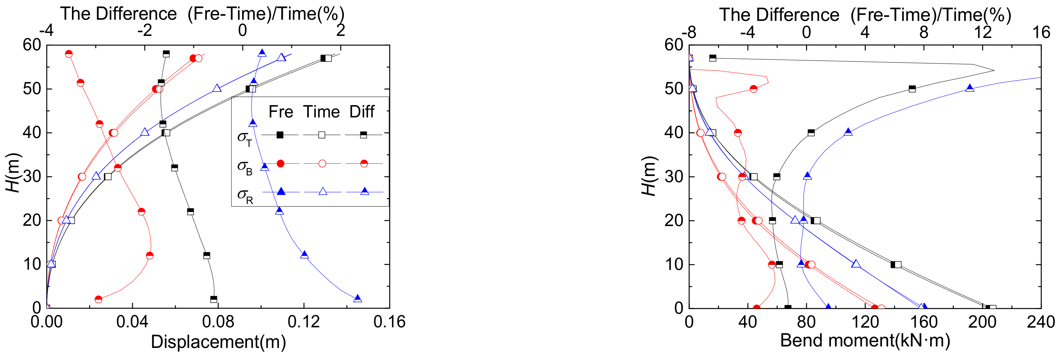
Figure 2 shows the curve of the displacements, bending moments and shear forces T, σB and σR, respectively), obtained by the frequency domain method and the time domain method, as well as the percentage of the coupled components in the total pulsation response obtained by the time domain method. As shown in the picture, the σT values obtained from the frequency domain and time domain methods are in good agreement, and the deviations in the displacement of the tower tip, the base bending moment and the base shear force are all within 1.5%. As regards the displacement and bending moment responses, the background response obtained by the frequency domain method is smaller, and the resonance response is larger, than those obtained by the time domain method. The percentage of σBR in the total pulsation response for each variable is less than 2%, so the effect of neglecting σBR on the total pulsation response is small.

3. The Assessment Method for the Equivalent Static Wind Load of Arbitrary Structural Response

Theoretical Analysis

As in previous studies, for high-rise buildings and towering structures, this paper still assumes that the equivalent static wind load on the structure is equal to the product of the mean wind load and the gust load factor, which can be expressed as follows:
P ^ ( z ) = G L F ( z ) P ¯ ( z )
G L F ( z ) = 1 + σ T ( z ) r ¯ ( z ) = 1 + σ B ( z ) 2 r ¯ ( z ) 2 + i n σ R i ( z ) 2 r ¯ ( z ) 2 = 1 + G B ( z ) 2 + i n G R i ( z ) 2
σ B ( z ) = g u 0 0 H 0 H 0 W 0 W p ( x 1 , z 1 , f ) p ( x 2 , z 2 , f ) ¯ i ( z , z 1 ) i ( z , z 2 ) d x 1 d x 2 d z 1 d z 2 d f 1 / 2
σ R j ( z ) = 0 H P ^ R j ( z ) i ( z , z ) d z
P ^ R j ( z ) = m ( z ) ( 2 π f j ) 2 σ Y R j φ j ( z ) = g R S F j ( f j ) π f j 4 ζ j 1 / 2 φ j ( z ) = g R k = 1 N l = 1 N ϕ i k ϕ j l ρ 2 C D 2 A k U ¯ k A l U ¯ l R X R Z S u ( f j ) S u ( f j ) π f j 4 ζ j 1 / 2 φ j ( z )
where P ^ R j ( z ) is the jth order modal resonant equivalent wind load at height z of the structure, and its value is equal to the inertia force caused by the jth order modal resonant displacement [38].
The background response σ B ( z ) and resonant response σ R ( z ) can be obtained according to Equations (25) and (26), respectively, and then bringing them into the GLF expression (Equation (24)) can give the expressions of the GB(z) and GR(z) at any position on the structure.
The background gust load factor GB(z) of the structure’s response when under wind load at any location is
G B ( z ) = σ B ( z ) r ¯ ( z ) = g B 0 0 H 0 H 0 W 0 W p ( x 1 , z 1 , f ) p ( x 2 , z 2 , f ) ¯ i ( z , z 1 ) i ( z , z 2 ) d x 1 d x 2 d z 1 d z 2 d f 0 H P ¯ ( z ) i ( z , z ) d z = 2 g B I H H α 0 h z 2 α i ( z , z ) d z + h H z 2 α i ( z , z ) d z 0 S u * ( f ) K Z ( α , z , f ) 2 | J X ( f ) | 2 d f
K Z ( α , z , f ) 2 = 0 z 0 z z 1 α z 2 α R Z ( z 1 , z 2 , f ) i ( z , z 1 ) i ( z , z 2 ) d z 1 d z 2 + 0 z z H z 1 α z 2 α R Z ( z 1 , z 2 , f ) i ( z , z 1 ) i ( z , z 2 ) d z 1 d z 2 + z H 0 z z 1 α z 2 α R Z ( z 1 , z 2 , f ) i ( z , z 1 ) i ( z , z 2 ) d z 1 d z 2 + z H z H z 1 α z 2 α R Z ( z 1 , z 2 , f ) i ( z , z 1 ) i ( z , z 2 ) d z 1 d z 2
Following the method of GLF based on displacement (DGLF), Davenport [15] defined the integral term in the structural force spectrum with respect to height z as a vertical joint receiver function. To make the above expression formally identical to the DGLF method, this paper also draws on this idea, and defines the integral term with respect to height z as a new function (Equation (29)), but the difference is that we use four integral terms.
The jth order modal resonant gust wind load factor GRj(z) of the structure, in terms of all responses at any location under wind load, is
G R j ( z ) = σ R j ( z ) r ¯ ( z ) = 0 H P ^ R j ( z ) i ( z , z ) d z 0 H P ¯ ( z ) i ( z , z ) d z = g R 0 H k = 1 N l = 1 N ϕ i k ϕ j l ρ 2 C D 2 A k U ¯ k A l U ¯ l R X R Z S u ( f j ) S u ( f j ) π f j 4 ζ j 1 / 2 φ j ( z ) i ( z , z ) d z 1 2 ρ U ¯ H 2 C D W 0 H ( z H ) 2 α i ( z , z ) d z
According to Equations (28) and (30), GB(z) and GR(z) can be determined by the height z and the influence function i(z, z′).

4. Example and Analysis

Yin Zhou [20] used a high-rise building as an example to illustrate the correctness of their proposed method of basal bending moment gust wind load factor (MGLF). In the following, the GLF, GB and GRj of the same structure are calculated according to the method given in this paper. The physical parameters of the structure are: dimensions H × W × D = 200 × 50 × 40 m, natural frequency f1 = 0.22 Hz; damping ratio ξ = 0.01; first order vibration mode φ1(z) = (z/H)β; mass distribution m(z) = m0(1 − λ(z/H)); m0 = 5.5 × 10⁵ kg/m; section drag coefficient CD = 1.3. The wind environment parameters are: fundamental wind speed U ¯ 10 = 30   m / s ; wind profile power index α = 0 . 15 ; and turbulence I10 = 0.2, while the wind spectrum type is Davenport wind spectrum, and the coherence function parameter CX = CZ = 11.5. The following four operating conditions are obtained by adjusting the values of the vibration index β and the mass discount factor λ, respectively (Table 1).
Zhou Yin (2001) calculated the values of GLF, GB and GR1 via the DGLF method proposed by Davenport, as well as the QGLF method, and the MGLF method, which was proposed by him. The DGLF method directly takes the first-order vibration mode as linear, i.e., the vibration index β = 1 (of course, the DGLF method can also obtain results when β ≠ 1), but the DGLF method itself cannot consider the mass discount of the structure along with the height. Therefore, Zhou could only derive the result of one of the above four conditions using the DGLF method. The MGLF method also divides the structure σ T into two parts: the σ B is calculated directly based on the wind load and influence function, and the σ R is calculated by the indirect method, which distinguishes the influence of β and λ, so the results of the four conditions are different. The results are presented in reference [20].
According to Equations (24), (28) and (29), the GLF, GB and GRj values at arbitrary positions are calculated, and when the height is taken as 0 or H, the GLF, GB and GR1 values at these positions can also be obtained—the results are shown in Table 2. The values in parentheses are the results relative to the results of Zhou Yin [20]. It can be seen that the GLF values of the base bending moments obtained by the method proposed in this paper are identical to those obtained by Zhou Yin [20]. The values of base shear force GLF and top displacement GLF deviate slightly, but the maximum deviation is only 0.6%, meaning they are consistent with each other. The expressions of the basal bending moment GLF and top displacement GLF obtained according to the method of this paper are identical to those of Zhou Yin [20]. The deviations in the result may be caused by numerical integration. Due to the different values derived for the respective integration step and the upper integration limit when numerical integration is performed, the integration results will be somewhat deviant. The specific values of these parameters are not given by Zhou Yin [20]. The first-order frequency of this high-rise building is f1 = 0.22 Hz; the trapezoidal integration formula is used in this paper for the numerical integration calculation, and the frequency integration step is df = 1/1000 Hz, while the upper integration limit is fMAX = 6 Hz. Other values are also taken (fMAX = 1 Hz, 3 Hz and 9 Hz; df = 1/500 Hz and 1/2000 Hz) for verification to ensure the calculation’s accuracy. The results show that the resulting GB decreases slightly when df = 1/500 Hz compared to df = 1/1000 Hz, but it remains unchanged when df = 1/2000 Hz, and the resulting GB decreases slightly when fMAX = 1 Hz and 3 Hz, compared to fMAX = 6 Hz, while it remains unchanged when fMAX = 9 Hz, which indicates that the df and fMAX used in the numerical integration are reasonable.
The values of the GLF of the tip displacement and its components GYB and GYR, obtained under the four working conditions, are the results for condition 1. Since the effects of β and λ can all be considered when calculating the displacement response using the method in this paper, different results can be obtained under each of the four conditions, and because of that, the results under conditions 2, 3 and 4 will not be compared.
From Table 2, it can be seen that under each working condition, the top displacement GLF is not less than the base bending moment GLF, with a maximum deviation of about 3.1%, and the base bending moment GLF is greater than the base shear force GLF, with a maximum deviation of 7.5%. The σ B values of the base bending moment and shear force are obtained directly from the load and influence function (Equation (25)), which does not contain parameters β and λ; therefore, the bending moment and shear force GB are not affected by β and λ, and GB is constant under all four conditions. Further, the base bending moment GB is slightly smaller than the base shear force GB, since the displacement influence function is obtained according to the assumption of the first-order vibration mode, and GYB increases with the increase of β. Since the σ R values of the base bending moment and shear force are obtained according to the resonant displacement inertia force P ^ R ( z ) and the influence function (Equation (26)), and P ^ R ( z ) contains the effects of β and λ, the σ R response of each condition is not same, and both GR values decrease with the increase in β. For the displacement of σ R , although both P ^ R ( z ) and the influence function contain the parameters β and λ, the parameter λ can be removed, so GYR is not affected by parameter λ, and only increases with the increase in β. The GMR decreases with the increase in β, but remains unchanged or increases when λ increases from 0 to 0.2, which is mainly because λ can be approximately removed when β = 1. When only the first-order vibration mode is considered, the GQR of base shear force decreases with the increase in β, and increases with the increase in λ.
Taking the above high-rise building as an example, the GLF values of each response at any position of the structure under different working conditions are obtained, and the different MGLF values and QGLF values relative to DGLF for each working condition are given in terms of DGLF values. The results are shown in Figure 3.
From Figure 3, it can be seen that with the increase in building height, the MGLF and QGLF corresponding to the four working conditions increase significantly, and the DGLF remains unchanged along the height. This is mainly because this paper uses the influence function based on the first-order vibration mode to calculate the DGLF, so the total pulsation response and the average response are in the form of the first-order vibration mode, and for MGLF and QGLF, the increase rate increases with the increase in β and decreases with the increase in λ. Under the same working conditions, the MGLF is larger than both the QGLF and the DGLF, and only the value of DGLF at the basal level is larger (slightly) than the MGLF, but the deviation is within 3%. Therefore, if DGLF and QGLF are used as the equivalent wind load in the structural design, the moment response of the structure may be underestimated; however, the use of the MGLF value for the equivalent wind load calculation is more important, because the design of the structure is biased towards safety, which is corroborated by the popular idea of using the bending moment as the control parameter for towering structures. Under the same working conditions, the basal QGLF value is the smallest, but as the building’s height increases, the QGLF value gradually increases, and when the height is above 100 m, the QGLF under each working condition is greater than the DGLF. As the building’s height increases, the difference between the MGLF and QGLF gradually decreases, until the tops tend to be equal, and the MGLF is greater than the DGLF. Until the top is reached, the difference between the MGLF value and the DGLF value gradually increases, and the maximum deviation between the MGLF and QGLF is about 22%, compared with DGLF. The position of maximum deviation is the top of the structure, so the wind effect of the structure will be seriously underestimated when the wind load design is based only on the base moment GLF.

5. Conclusions

This paper presents an assessment method for the equivalent static wind load based on random vibration theory and quasi-steady aerodynamic theory, and investigated a method for analyzing the background response, the resonant response, and the coupling components between these two responses, to wind vibration in the time domain and the frequency domain. The main conclusions are as follows:
(1) The displacement and bending moment responses obtained by the time domain and frequency domain methods are in good agreement, and the deviation in the base shear force response of the structure is slightly increased. However, the deviation in the total pulsation response is within 1.5%, and the percentage of σBR in the total pulsation response of each response is within 2%, so the influence of neglecting σBR on the total pulsation response is small;
(2) The MGLF and QGLF obtained by the new assessment method in this paper increase significantly with height, while the traditional GLF methods underestimate the maximum wind effects. The DGLF is constant as the height increases, and the MGLF at the top of the structure is about 22% larger than the DGLF. At this time, if only the DGLF or the base location MGLF values are considered, the wind effect of the structure will be seriously underestimated. The DGLF, MGLF and QGLF values increase as the β increases, and the MGLF and QGLF values decrease as the λ increases;
(3) The differences between the GLF obtained in this paper and the traditional gust load factor method are compared through the case of a high-rise building, and the validity of this paper’s method is verified. The GLF assessment method of this paper considers the higher-order vibration pattern of the structure and the whole wind-induced response, including displacement, bending moments and shear forces. It has a wide range of applications.

Author Contributions

J.Z. and C.L. conceived the idea and designed the framework; J.Z. set up the numerical model; J.Y. analyzed the simulation data; and J.Y. and C.L. writing—review and editing the paper. All authors have read and agreed to the published version of the manuscript.

Funding

Shenzhen Basic Research Program (JCYJ20190806145216643) and National Natural Science Foundation of China (51778200).

Institutional Review Board Statement

Not applicable.

Informed Consent Statement

Informed consent was obtained from all subjects involved in the study.

Acknowledgments

This research has received support from the Shenzhen Basic Research Program (JCYJ20190806145216643) and National Natural Science Foundation of China (51778200), all of which are gratefully acknowledged.

Conflicts of Interest

The authors declare no conflict of interest.

References

  1. Longarini, N.; Cabras, L.; Zucca, M.; Chapain, S.; Aly, A.M. Structural Improvements for Tall Buildings under Wind Loads: Comparative Study. Shock Vib. 2017, 2017, 2031248. [Google Scholar] [CrossRef] [Green Version]
  2. Chapain, S.; Aly, A.M. Vibration attenuation in high-rise buildings to achieve system-level performance under multiple hazards. Eng. Struct. 2019, 197, 109352. [Google Scholar] [CrossRef]
  3. Scanlan, R. The action of flexible bridges under wind, II: Buffeting theory. J. Sound Vib. 1978, 60, 201–211. [Google Scholar] [CrossRef]
  4. Su, Y.; Di, J.; Li, S.; Jian, B.; Liu, J. Buffeting Response Prediction of Long-Span Bridges Based on Different Wind Tunnel Test Techniques. Appl. Sci. 2022, 12, 3171. [Google Scholar] [CrossRef]
  5. Brownjohn, J.; Carden, E.; Goddard, C.; Oudin, G. Real-time performance monitoring of tuned mass damper system for a 183m reinforced concrete chimney. J. Wind Eng. Ind. Aerodyn. 2010, 98, 169–179. [Google Scholar] [CrossRef]
  6. Gao, D.; Chen, G.; Chen, W.; Huang, Y.; Li, H. Active control of circular cylinder flow with windward suction and leeward blowing. Exp. Fluids 2019, 60, 26. [Google Scholar] [CrossRef]
  7. Bernuzzi, C.; Crespi, P.; Montuori, R.; Nastri, E.; Simoncelli, M.; Stochino, F.; Zucca, M. Resonance of steel wind turbines: Problems and solutions. Structures 2021, 32, 65–75. [Google Scholar] [CrossRef]
  8. Rahman, M.; Ong, Z.C.; Chong, W.T.; Julai, S.; Khoo, S.Y. Performance enhancement of wind turbine systems with vibration control: A review. Renew. Sustain. Energy Rev. 2015, 51, 43–54. [Google Scholar] [CrossRef]
  9. Sari, D.P.; Cho, K.-P. Performance Comparison of Different Building Shapes Using a Wind Tunnel and a Computational Model. Buildings 2022, 12, 144. [Google Scholar] [CrossRef]
  10. Song, Y.; Zhang, M.; Øiseth, O.; Rønnquist, A. Wind deflection analysis of railway catenary under crosswind based on nonlinear finite element model and wind tunnel test. Mech. Mach. Theory 2021, 168, 104608. [Google Scholar] [CrossRef]
  11. Gao, D.; Chen, W.; Zhang, R.; Huang, Y.; Li, H. Multi-modal vortex- and rain–wind- induced vibrations of an inclined flexible cable. Mech. Syst. Signal Process. 2019, 11, 8245–8258. [Google Scholar] [CrossRef]
  12. Chen, W.-L.; Zhang, Q.-Q.; Li, H.; Hui, L. An experimental investigation on vortex induced vibration of a flexible inclined cable under a shear flow. J. Fluids Struct. 2015, 54, 297–311. [Google Scholar] [CrossRef]
  13. Zhong, Y.; Li, S.; Jin, W.; Yan, Z.; Liu, X.; Li, Y. Frequency Domain Analysis of Alongwind Response and Study of Wind Loads for Transmission Tower Subjected to Downbursts. Buildings 2022, 12, 148. [Google Scholar] [CrossRef]
  14. Davenport, A.G. The Application of Statistical Concepts to the Wind Loading of Structures. Proc. Inst. Civ. Eng. 1961, 19, 449–472. [Google Scholar] [CrossRef]
  15. Davenport, A.G. Gust Loading Factors. J. Struct. Div. 1967, 93, 11–34. [Google Scholar] [CrossRef]
  16. Zhang, X. Wind Load Theory and Wind-Resistance Design Manual for Engineering Structures; Tongji University Press: Shanghai, China, 1990; pp. 92–98. [Google Scholar]
  17. Kasperski, M.; Niemann, H.-J. The L.R.C. (load-response-correlation)-method a general method of estimating unfavourable wind load distributions for linear and non-linear structural behaviour. J. Wind Eng. Ind. Aerodyn. 1992, 43, 1753–1763. [Google Scholar] [CrossRef]
  18. Kasperski, M. Design wind loads for low-rise buildings: A critical review of wind load specifications for industrial buildings. J. Wind Eng. Ind. Aerodyn. 1996, 61, 169–179. [Google Scholar] [CrossRef]
  19. Zhou, Y. Theoretical and Experimental Study of High-Rise Building Static Equivalent Wind Loads and Response; Tongji University: Shanghai, China, 2001. [Google Scholar]
  20. Zhou, Y.; Kareen, A. Gust loading factor: A new model. ASCE J. Struct. Eng. 2001, 127, 168–175. [Google Scholar] [CrossRef]
  21. Holmes, J. Effective static load distributions in wind engineering. J. Wind Eng. Ind. Aerodyn. 2002, 90, 91–109. [Google Scholar] [CrossRef]
  22. Holmes, J.D. Wind Loading of Structure; Spon Press: London, UK, 2001. [Google Scholar]
  23. Gu, M.; Ye, F. Characteristics of wind induced responses and equivalent static wind loads of tall building. Eng. Mech. 2006, 23, 93–98. [Google Scholar] [CrossRef]
  24. Ye, F.; Gu, M. Along-wind background response and background equivalent wind loads of tall buildings. J. Build. Struct. 2002, 23, 58–60. [Google Scholar] [CrossRef]
  25. Xie, Z.N.; Fang, X.D.; Ni, Z.H. Equivalent static wind liads on tall building the extended load response correlation (ELRC) approach. J. Vib. Eng. 2008, 21, 398–403. [Google Scholar] [CrossRef]
  26. Lin, Y.; Lin, C.; Lin, X.; Zhang, J.; Song, J. Research on equivalent static load of high- rise buildings based on wind-induced responses. J. Southwest Jiaotong Univ. 2019, 54, 137–144. [Google Scholar]
  27. Ke, S.; Ge, Y. Refined research on wind-induced response of roof structure of a large museum based on consistent coupled method. J. Build. Struct. 2012, 33, 111–117. [Google Scholar]
  28. Cao, S.; Ke, S.; Zhang, W.; Zhao, L.; Ge, Y.; Cheng, X. Load–response correlation-based equivalent static wind loads for large cooling towers. Adv. Struct. Eng. 2019, 22, 2464–2475. [Google Scholar] [CrossRef]
  29. Zhang, J.-F.; Ge, Y.-J.; Zhao, L.; Zhu, B. Wind induced dynamic responses on hyperbolic cooling tower shells and the equivalent static wind load. J. Wind Eng. Ind. Aerodyn. 2017, 169, 280–289. [Google Scholar] [CrossRef]
  30. Solari, G. Wind Loading of Structures: Framework, Phenomena, Tools and Codification. Structures 2017, 12, 265–285. [Google Scholar] [CrossRef]
  31. Gu, M.; Zhou, X.; Huang, P. A study on wind-induced buffeting responses of large-span roof structures. China Civ. Eng. J. 2006, 39, 37–42. [Google Scholar] [CrossRef]
  32. Li, S.K.; Li, S.Y.; Fang, X.L.; Sun, H.X.; Li, H.L. Refined study on wind-induced response of structure by stochastic wind load. Eng. Mech. 2015, 32, 111–115. [Google Scholar] [CrossRef]
  33. Zou, L.; Shi, T.; Liang, S.; Song, J.; Li, F. Simplified calculation of along-wind dynamic responses of high-rise buildings considering second mode. J. Build. Struct. 2018, 39, 18–25. [Google Scholar] [CrossRef]
  34. Zhang, J.; Liu, Q.; Yang, J.; Tu, B. A method of separating the background and resonant components of wind dynamic effects in time domain. J. Disaster Prev. Mitig. Eng. 2020, 40, 365–371. [Google Scholar]
  35. Zeng, J.; Li, M.; Li, S. Spatial correlation of downwind pulsating wind loads in rectangular high-rise buildings. J. Harbin Inst. Technol. 2017, 49, 150–155. [Google Scholar]
  36. Yu, P. Research on Wind Vibration Response of Substation Lightning Rod Structure Downwind; Zhengzhou University: Zhengzhou, China, 2018. [Google Scholar]
  37. Ministry of Housing and Urban-Rural Development of the People’s Republic of China. GB 50009-2012. Code for Structural Loading of Buildings; China Construction Industry Press: Beijing, China, 2012.
  38. Gu, M.; Ye, F. Along-wind equivalent wind loads and responses on tall buildings. J. Wind. Eng. 2001, 89, 609–612. [Google Scholar]
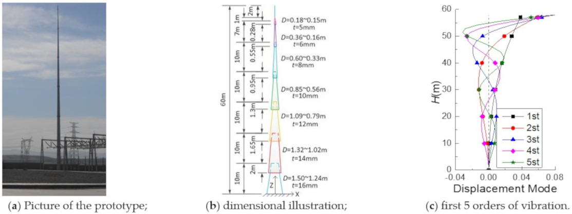
Figure 1. Geometry parameters and the FE model of the lightning rod.
Applsci 12 03729 g001
Figure 2. Comparison of time/frequency domain results and the percentage of coupling components.
Applsci 12 03729 g002aApplsci 12 03729 g002b
Figure 3. GLF values obtained by the method in this paper and their difference rates.
Applsci 12 03729 g003
Table 1. The values of the parameters for the four working conditions [20].
ConditionVibration Index βMass Discount Factor λ
11.00.0
21.60.0
31.00.2
41.60.2
Table 2. GLF of feature locations obtained in this paper.
Top DisplacementBasal Bend MomentBasal Shear Force
ConditionGYBGYRDGLFGMBGMRMGLFGQBGQRQGLF
10.6520
(1.000)
0.9761
(0.998)
2.1738
(0.999)
0.6520
(1.000)
0.9761
(1.000)
2.1738
(1.000)
0.6560
(0.994)
0.8275
(1.002)
2.0560
(1.000)
20.65911.03022.22300.6520
(1.000)
0.9532
(1.000)
2.1549
(1.000)
0.6560
(0.994)
0.7460
(1.003)
1.9934
(0.999)
30.65200.97612.17380.6520
(1.000)
0.9761
(1.000)
2.1738
(1.000)
0.6560
(0.994)
0.8438
(1.001)
2.0688
(0.999)
40.65911.03022.22300.6520
(1.000)
0.9589
(1.000)
2.1596
(1.000)
0.6560
(0.994)
0.7612
(1.002)
2.0049
(1.000)
Publisher’s Note: MDPI stays neutral with regard to jurisdictional claims in published maps and institutional affiliations.