Abstract
Multiple-input multiple-output (MIMO) wireless system is a hot research topic in 5th generation mobile communication technology (5G), which can increase the channel capacity of the antenna system to meet new communication demands without changing the bandwidth and transmission power. However, adding the number of antenna elements in a limited space size can lead to mutual coupling effects and impair the communication quality. Therefore, it is significant to design a compact MIMO wireless system using decoupling techniques. Several studies on the reduction of mutual coupling effects have been proposed. However, a concrete overview of the features and resemblances of these decoupling techniques is lacking. In this review, we provide a brief description of the research background on the mutual coupling effect of MIMO. Then, various decoupling techniques worthy of reference are classified and outlined. We further summarize the additional impacts due to the existence of different decoupling structures, and the possible usability and defects of these techniques are revealed clearly in this paper. Finally, a future outlook on the development direction of decoupling techniques for MIMO wireless systems is also concluded and discussed.
1. Introduction
Currently, the field of mobile communication technology is in the transition phase from 4G to 5G technology. The explosive growth of mobile data is driving the users’ demands for higher wireless communication services. Communication systems need to achieve timely and fast access to information, higher transmission efficiency, and better system security. As a result, 4G is starting to gradually fail to meet the new communication needs and the shortcomings are coming to the fore. From 2020, 5G took the stage of commercialization, which marked it was gradually becoming the mainstream technology in modern mobile communication. Its frequency band covers sub-6 GHz (450 MHz–6 GHz) and mm-Wave band (24.25–54.6 GHz). The salient features of 5G are high-speed data transfer, and reliable connectivity with zero percent latency [1]. Additionally, the good user’s Quality of Experience (QoE) in the 5G era requires excellent antenna diversity and larger channel capacity support.
To overcome the signal fading due to multipath effects, diversity systems with two receivers were developed, which was the beginning of the evolution of MIMO [2,3]. Existing studies [4,5] have shown that, compared to simple input simple output (SISO) systems with a simple structure, MIMO systems have multiple additional paths, and the multipath effect, delay, and packet loss can be reduced to enhance the communication modes. Moreover, according to Shannon’s theorem, the channel capacity depends on the channel bandwidth and signal-noise ratio (SNR). Additionally, MIMO systems have demonstrated the potential for increasing the data throughput multiple times with a fixed bandwidth and transmission power by virtue of the multi-port design [6,7]. Therefore, the study of MIMO systems is an important part of developing 5G communication systems.
MIMO systems applied to 5G devices are a hot research topic in the field of antenna design recently, so many related papers have been published, and they are compared in Table 1. The eight-port MIMO system composed of I-shaped slot antennas was proposed by Li et al. [8]. To ensure the system isolation of this dual-band MIMO system, four antenna elements are arranged along each side of the ground plane. Each antenna element is kept at a distance of more than 15 mm, and the isolation is better than 11 dB. The tri-band antenna was designed by Qin et al. [9], which consisted of eight inverted F-shaped antennas. The antenna elements were evenly distributed along both sides of the ground plane to obtain isolation higher than 10 dB. In Li et al. [10], a 12-port MIMO system consisting of an inverted π-shaped antenna was proposed. To ensure the isolation higher than 12 dB, the antenna element spacing was not less than 10 mm. It can be observed from Table 1, that although these antenna systems can meet the practical requirements, their average isolation is only around 11 dB while the average distance between antenna elements is more than 15 mm. This is because the limitation of physical size leads to the mutual coupling effect between antenna elements, which can impair the isolation of MIMO systems. Therefore, it is not a recommended method to obtain satisfactory isolation by just adjusting the antenna element position, and some effective techniques are needed to reduce the mutual coupling.

Table 1.
Comparison among the referenced techniques of distance optimization.
In this paper, our investigation focuses on decoupling techniques for MIMO systems. We review some excellent MIMO decoupling schemes of the last five years and discuss the potential works it faces. These decoupling techniques are divided into two types, including external decoupling techniques and internal decoupling techniques. External decoupling techniques rely on adding additional structures to counteract the mutual coupling, which are further classified into neutralization lines (NL), grounding branch structures, parasitic decoupling elements (PDE), defective ground structures (DGS), metamaterial techniques, etc. Internal decoupling techniques are related to polarization diversity, where orthogonal polarization and multi-polarization are commonly used. The rest of this paper is as follows. The second part emphasizes the causes of mutual coupling and its negative effects on MIMO systems. The third part briefly describes how to evaluate the degree of mutual coupling by performance parameters. Part four discusses some decoupling schemes for MIMO wireless systems applicable in 5G devices. The fifth part is a detailed analysis of the advantages and disadvantages of each decoupling technique. Finally, it is conclusion and envisages the future development direction of decoupling techniques.
2. Mutual Coupling Issue of MIMO Systems
2.1. Causes of Mutual Coupling
The information theoretical capacity grows linearly with the number of elements in the MIMO systems [7]. Later, Wallace and Jensen [11] pointed out that the linear increase of channel capacity was not unconditional, which was achieved by arranging antenna elements with wide spacing (more than several wavelengths). However, it is unrealistic for modern mobile users because most 5G applications, especially portable devices, are composed of integrated circuits and the spacing of each antenna element is not allowed to exceed one wavelength. In this narrow space, the electromagnetic interference existing between antenna elements is known as the mutual coupling effect, which is an unavoidable issue in MIMO systems.
Probing the causes of mutual coupling, the focus is on analyzing the effect of current. As regardless of the form of the antennas, the working principle of the antennas is based on the common mechanism of radiation generated by variable speed charges [12]. There are three sources of mutual coupling effects in MIMO systems, as follows.
- Near field coupling. When antennas are closely spaced, they are in near field zone of another antennas and the effect from near field EM waves is dominant [13]. This fields decay follow distance as or [14];
- Surface-wave coupling. This coupling often occurs in microstrip antennas, due to sharing the same ground plane [15]. During the feeding process of the antenna element at the feed point, a distributed current is generated on the ground plane. This current will flow to nearby antenna elements, dispersing the energy and creating interference;
- Free-space coupling. This is because in the process of radiating electromagnetic (EM) waves outward from the excitation element, part of the energy will be coupled on the adjacent antennas and excite the adjacent antennas to generate new currents. In general, the contribution to the mutual coupling of the surface wave is smaller than the space wave due to the fields of surface wave decay as , which is slower than dependence of space wave coupling [14,16].
2.2. Negative Effects of Mutual Coupling
The impact of mutual coupling on MIMO systems is like a coin with two sides, containing both beneficial and detrimental aspects. Of these, detrimental impacts are the focus of this paper. Firstly, the mutual coupling has a significant effect on the average bit error ratio (BER) of MIMO systems, especially at separations 0.3–0.5 wavelength of antenna elements [17]. Additionally, in terms of radiation pattern [18,19,20], a distortion of radiation pattern occurs in MIMO antennas compared to the isolated radiation pattern of each element. Additionally, in terms of direction-of-arrival (DOA) [21,22,23], the estimation accuracy of DOA may degrade substantially, especially when the MIMO systems operate at high frequency or very high frequency because the array manifold is often affected by mutual coupling. Lastly, the high capacity of MIMO can be estimated with bias if various coupling receivers are in the terminal [24,25,26]. When the receivers spacing is around 0.35–0.5 wavelength, the received SNR is dropped by the effect of mutual coupling, which leads to the actual channel capacity being lower than expected.
To sum up, the influences of mutual coupling on MIMO systems can be recognized from the following two aspects. As for output terminals, the desired EM field is generated by the currents with a particular frequency. Due to the tight distance, the transmitting antennas are easily affected by EM fields which are generated by their currents and adjacent antennas. Thus, the phase and amplitude of the original current are changed by the superposition of different EM fields. As for input terminals, when the input signals are transmitted to the receiving port, the current is not only induced, but also radiated again. Therefore, the essence of the signal obtained at the receiving port is the vector sum of the EM wave, which is generated by output terminals and the re-radiated fields. We can see that it is necessary to overcome the detrimental effects of mutual coupling in MIMO systems.
3. Evaluation Parameters of Mutual Coupling
There are many parameters to judge the behavior of MIMO systems, including performance parameters, such as operating band, matched impedance, channel capacity, etc., and diversity performance parameters, like envelop correlation coefficient (ECC), diversity gain (DG), total active reflection coefficient and mean effective gain (MEG). The evaluation of the degree of mutual coupling between antenna elements is usually characterized by the S-parameter and ECC. These two parameters are briefly introduced in the following section to set the stage for the analysis of MIMO decoupling techniques later.
3.1. S-Parameters
Viewing an array of antenna elements as a network with n-port. Assuming that the incident waves of the n-port network are , and the outgoing waves are , the relationship between the outgoing and incoming waves can be expressed by Equation (1):
Expressed in matrix form, Equation (1) is as follows:
Of which:
Among them, is called “reflection coefficient”. It indicates the voltage reflection of the port when other ports are connected to the matching load. As we all know, the operation bandwidth of a MIMO system is decided by its impedance matching situation. Adding any decoupled structures will change the radiation impedance of the proposed antenna arrays. Thus, needs to be referenced when we consider decoupling design because it represents impedance match indirectly. By adjusting , desired operation bandwidth can be attained. is called “transmission coefficient”. It represents the voltage transmission from port to port when the element is connected to the matching load. The mutual coupling degree of two ports is measured by . Additionally, the preferred isolation is achieved by modifying . The unit of these parameters is usually expressed in “dB”. To ensure that the RF element is in a normal working state, it is generally required be less than −6 dB and be less than −10 dB.
Taking the two-port network as an example, assume that 1 is the feed port and 2 is the coupling port. The S-parameters of the two-port network are given in Equation (6):
where is the input reflection coefficient, or input return loss; is the output reflection coefficient, or output return loss; is the reverse transmission coefficient or isolation; and is the forward transmission coefficient, or gain.
Assuming that the power of port 1 is and the power of port 2 is , the isolation of the ports can be given by Equation (7):
The degree of mutual coupling of the antenna element is inversely related to the absolute value of the transmission coefficient. Therefore, the larger the absolute value of the transmission coefficient, the smaller the degree of mutual coupling of the antenna.
3.2. Envelope Correlation Coefficient (ECC)
A good diversity effect is a key to ensuring the communication quality of MIMO systems. The effect of diversity depends on the correlation of antenna signals. The envelope correlation coefficient, as a measurement parameter, is used to measure the degree of similarity between different signals and can also be used as a basis for judging the mutual coupling of different ports.
The most accurate ECC calculation method is based on the far-field pattern function. it can be given by Equation (8):
is a function of the radiation pattern of the field when port is excited, and the other ports are matched under the condition of , “” represents the Hermite product. However, due to the complex measurement process and the limitation of available pattern characterization tools, this method is time-consuming.
Boris et al. [27] showed how to compute the ECC from the S-parameter description of the two-antenna system. The equation has been derived using the law of energy conservation, which has the advantage that it does not require the computation or the measurement of the radiation pattern of the antenna system. It is given by Equation (9):
Further, Thaysen and Jakobsen [28] deduced that in a MIMO system consisting of antenna elements, the ECC between antenna elements and antenna elements can be expressed by Equation (10):
However, Equation (10) is only applicable to the ideal case where the antenna is loss-free. In practical applications, the realistic power losses of the antenna structures should be taken into account. Dama et al. [29] proposed a modification of the S-parameter method which included the antenna losses. It is expressed in the two-antenna system as Equation (11):
The elements and are obtained from the power loss calculation.
In addition, a modification of the S-parameter method that took into account the effects of the radiation efficiency was proposed in [30]. However, instead of giving the exact value, it gave an upper bound for ECC. It is expressed by Equation (12):
where and are the radiation efficiency of antenna elements and , respectively. Additionally, once the efficiency goes below 60%, the errors start increasing dramatically.
The smaller the value of ECC, the lower the mutual coupling effect. When ECC = 0, it means that the relationship between the two ports is completely independent. It is usually considered that MIMO systems with ECC below 0.5 can run normally. When calculating ECC, the above equations can be flexibly selected.
4. The Methods of Decoupling
In recent years, many decoupling solutions have been proposed to make the MIMO systems either meet isolation requirements or improve the channel capacity, which can be initially divided into external decoupling techniques and internal decoupling techniques according to the decoupling principle.
4.1. External Decoupling
The external decoupling is based on adding additional structures between adjacent antenna elements. According to different mutual coupling suppression mechanisms, two categories can be further classified. Some introduce a new coupling path to offset the original coupling, such as adding the structure of neutralization lines (NL), parasitic decoupling elements (PGE), etc. Others are to control or reduce the flow of surface currents, such as defective ground structures (DGS), grounding branches, metamaterials techniques, etc.
4.1.1. NL Technique
The principle of NL techniques is based on conducting an out-phase current path to offset the original coupling between two antenna elements. The physical structure of NL is vital to the decoupling effect, which the length determines the inductance and the width represents the capacitance. Selecting the proper location of NLs is a design art. Although research [31] pointed out that the strip linked the feeding or the shorting line of plane inverted-F antennas (PIFAs) was an effective decoupling method, there is no common theory for arranging NLs available now.
The neutralization line structure was used in compact MIMO systems with elements spacing of no more than one wavelength. To save space, a meandering NL was used in [32]. It can be observed from the surface current distribution that added NL prevented the current from flowing to other elements and the isolation was better than 16 dB. Moreover, as shown in Figure 1a, the multi-NLs structure can also be applied to multi-band MIMO [33]. The two U-shaped lines corresponding to different frequency decoupling was proposed. As shown in the comparison without and with decoupling structure in Figure 1b, the proposed new paths can effectively resist the mutual interference between antenna elements, and the isolation of tri-band MIMO can achieve better than 18 dB.
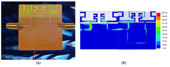
Figure 1.
MIMO antenna with NLs: (a) fabricated MIMO antenna; and (b) comparison of current distributions without and with grounding NLs (Results from Liu et al. [33]).
Since the NL can be conformal with the radiation elements, it can be often found in portable devices’ MIMO systems. In [34], the eight-port MIMO for 5G smartphones was designed. Each antenna element consisted of a meandering monopole and a gap-coupled loop branch and was placed on a bezel with a height of 6 mm. The adjacent antenna elements were spaced only 10 mm apart, and NL was connected to the loop branch. The isolation was better than 11 dB. A meandering NL was used in the dual-port MIMO system applicable in 5G laptops [35]. Its isolation was enhanced by up to 8 dB.
4.1.2. PDE Technique
Parasitic decoupling elements as decoupling structures can be placed flexibly, such as above, below, or indirectly in contact with the antenna element. They help to induce reverse coupling, which prevents the currents flow to neighboring elements.
A hybrid PDE structure composed of a circular patch and four L-shaped strips was printed on the upper surface of the four-port MIMO system in Figure 2 [36]. Due to the surface current on the decoupling patches, not only the isolation was improved to 15.4 dB, but also the impedance bandwidth was widened. The C-shaped patch was added as PDE near the circular radiation element [37]. Compared with the original design without the decoupling method, the isolation was increased by 9 dB, and bandwidth was extended by 250 MHz in the compact MIMO with the element spacing of 0.32 wavelength. The quad-element ultra wide band (UWB) MIMO with PDE placed on the backside was designed [38]. In order to meet the wideband characteristic of the proposed antenna array, the parasitic element with different features was adopted to cover the whole band decoupling. More than 20 dB isolation can be obtained.
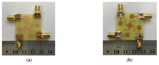
Figure 2.
MIMO antenna with PDE: (a) front view; and (b) back view. (Results from Yang and Zhou, [36]).
Antenna decoupling surface (ADS) as a deformed PDE was firstly proposed in 2017 [39]. ADS is a thin substrate loaded with a series of small metal patches. The function of ADS is to cancel the coupling wave with the help of the reflecting wave from the ADS [40]. The hybrid decoupling scheme constituted of ADS and DGS was applied in the MIMO system with element spacing of only 1 mm [41]. Those metal reflectors consisted of two groups ADS. One was formed by window-shaped sheets as a main reflected element. The other was three cross-shaped sheets to fill the leak. The isolation improvement mainly depended on the distance above the patch and ADS and the results more than 20 dB in 1 GB bandwidth can realize.
4.1.3. DGS Technique
By etching periodic or non-periodic slots on the antenna frame, the ground current on the antenna arrays can be effectively suppressed. The location is usually selected on the opposite sides to antenna elements, which are under the patch or in the middle of two elements. The behaviors of DGS act as the bandstop filter to ensure high isolation of ports placed closely.
The decoupling method by combining DGS with complementary split-ring resonator (CSRR) was used in a two-port MIMO for vehicular communication as depicted in Figure 3a [42]. For realizing acquired isolation, five slots were etched with split ring as DGS on the ground plane. The current density as shown in Figure 3b, which was found higher in radiation patches and a little in the ground plane with DGS determined effective isolation of >15 dB was achieved. A ten-port MIMO for 5 G mobile terminals was proposed [43]. The function of the proposed DGS was analyzed by CMA. It can be observed that the current was mainly concentrated on the slot with DGS rather than the entire frame. Thus, the isolation became higher and was better than 10 dB. The best location for placing DGS pointed by Liu et al. [44] was the part with disordered currents to guide the current flow to the DGS slot. In order to get high isolation, hybrid decoupling structures were adopted, in which DGS decoupling slots on the back were combined with two EBG structures on the front. The decoupling results indicated that two decoupled structures played different roles, where EBG worked as high impedance blocked wave propagation and DGS guided currents flow along with the slots. The isolation was better than 20 dB.
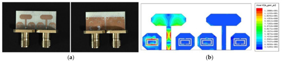
Figure 3.
MIMO antenna with DGS and CSRR: (a) geometry of proposed MIMO; and (b) the current distributions with hybrid decoupling structures (Results from [42]).
Moreover, different shapes of DGS slots can work together to improve isolation and bandwidth at the resonance frequency. The DGS with two zigzag grooves was arranged between two radiation patches on the opposite side to reduce coupling currents [45]. The grounding plane with rectangular, circular, and zigzag-shaped slots was designed [46]. From the consequence, the bandwidth and isolation (>17 dB) of the four-port mm-wave MIMO were enhanced at the same time.
4.1.4. Grounding Branch Technique
The grounding branch blocks the surface current by inserting the metal strip between two compact elements for coupling reduction. The larger the physical dimensions of added grounding branches mean the stronger the introduced inductance, which can create the mutual coupling effect minima.
By sharing a common rectangular grounding branch between two neighboring antenna elements, a self-decoupled four-port MIMO system was established [47]. As shown in the current distribution diagram, the characteristic of the grounding branch structure can be observed clearly. The current almost did not spread from one antenna element to another, although there was a 1.2 mm distance between them only. The MIMO system was optimized at a working frequency of 3.5 GHz, and isolation was better than 17 dB. Furthermore, the author upgraded this system to a dual-band system as shown in Figure 4, and the common ground branch was lengthened accordingly [48]. This design can provide isolation of better than 17.5 dB. A multi-branch T-shaped grounding branch was inserted in the ground plane to realize the decoupling of a UWB MIMO [49]. With adding the branches of the decoupling structure, the input impedance increased and the isolation improved to >15 dB. The T-shaped grounding branches were placed on the opposite side from antenna elements in Yu et al. [50]. More than 15 dB isolation was obtained between the eight-port MIMO. The two meandering grounding branches were introduced between two antenna pairs [51]. Additionally, the optimized length of the proposed decoupling structure was one-quarter wavelength at the resonance frequency. The isolation was achieved at more than 12 dB in this ten-port MIMO.
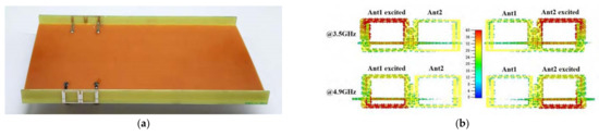
Figure 4.
MIMO antenna with grounding branches: (a) geometry of proposed MIMO; and (b) the current distributions with DGS (Results from [48]).
4.1.5. Metamaterials Technique
Metamaterials are a kind of artificial structure to achieve mutual coupling reduction by affecting EM wave transmission. In metamaterial structures design, the negative permeability or permittivity can be constructed depending on requirements, which was described fully by Smith et al. [52]. Thus, the propagation of EM waves can be altered in these structures with negative refractive indexes, which is opposite to the dielectric in nature. The electromagnetic band gap (EBG), split-ring resonator (SRR) and CSRR are commonly used types of metamaterials.
The EBG and SRR can be equated to a resonator circuit, in which the microstrip lines are represented for inductance and the thin gap between them acts as capacitance. A four EBG array was inserted between two antenna elements as in Figure 5a [53]. Multiple stop bands were exhibited by the EBG array. The performance that EBG effectively suppresses the undesired surface waves excited in the E-plane was shown in Figure 5b and E-plane coupling was suppressed (>18 dB). A ten CSRR array was etched from the ground plane between two elements [54]. Additionally, the improvement of isolation about 41.26 dB can be observed by introducing CSRR.
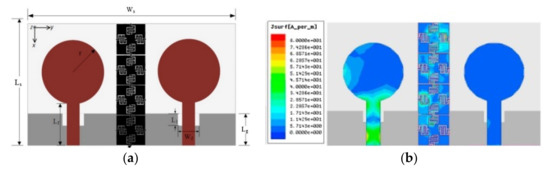
Figure 5.
MIMO antenna with EBG: (a) geometry of proposed MIMO; and (b) current distributions (Results from [53]).
A metamaterial based on SRR was introduced and acceptable isolation can be attained [55,56,57]. The surface current distribution showed that the SRR structures placed on the bottom of each antenna element tended to increase the current density and the current boundaries were established [55]. Thus, the coupling effect was controlled with isolation better than 20 dB. A near-field resonator (NFR) consisting of five split rings was proposed [56]. It was observed from E-field distributions with decoupled arrays, the NFRs were attached above each patch element and acted as coupling-mode transformation. The two neighboring elements with NFRs performed orthogonal modes. Therefore, the isolation was further improved to more than 20 dB. In [57], an additional SRR structure was placed on the top layer. The third resonance frequency at 5.1 GHz was compared without SRR and isolation better than 14 dB.
4.2. Internal Decoupling
The internal decoupling provides good solutions to isolation improvement relies on antenna diversity, such as pattern diversity, spatial diversity, and polarized diversity. The relationship between antenna diversity and mutual coupling was recognized in [27]. The isolation enhancement was achieved by constituting some radiation elements with different polarization characteristics, which can be of any type of antenna, such as patch, slot and substrate integrated waveguide. Thus, additional decoupling structures are not needed. Among them, the focus in the open literature was orthogonal polarization.
4.2.1. Orthogonal Polarization Technique
Constructing a dual orthogonal polarization antenna module is a general approach to internal decoupling. The four-antenna MIMO suitable for 5 G smartphones was designed [58]. The proposed antenna pair was composed of a split on the metallic bezel and a slot on the ground. Additionally, the currents around the slot were in-phase to produce y-axis polarization while the currents besides the split are out-phase, producing x-axis polarization. Therefore, two orthogonal modes within the same antenna area were excited, and more than dB isolation was obtained. Furthermore, the author modified the above MIMO system [59]. A T-shaped monopole was inserted in the slot on the long ground edge to constitute the CPW-fed dual antenna pair. Feeding from two ports, the two orthogonally polarized radiation can be generated by monopole and slot, respectively. Good isolation of better than 20 dB can be obtained. The 8 × 8 MIMO for a metal-rimmed smartphone with two sets of orthogonal characteristic modes was designed in [60]. The antenna element with polarized diversity consisted of T-shaped monopole and coupling-fed dipole, slot and split. In consequence, even though dual-antenna pairs shared a common radiator, the isolation in the lower and higher bands can be better than 12 dB. Based on conventional dual-port feeding patch antenna, a modified square loop antenna with two coupled feeding strips was proposed as shown in Figure 6 [61]. Due to this structure, the feature that two orthogonal modes share one common radiation element can be kept and the bandwidth was further improved. The isolation of more than 11.4 dB can be obtained in its eight-port MIMO system.
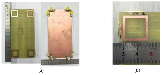
Figure 6.
MIMO antenna with orthogonal polarization: (a) geometry of proposed MIMO; and (b) antenna element with dual-polarized modes (Results from [61]).
Further, the triple orthogonal polarization modes are also applied in the decoupling scheme of the MIMO system. The twelve-port MIMO in Li et al. [62] provided tri-polarized modes for 5 G smartphones. The orthogonal polarization bloke was formed by two slot radiation elements and a quarter mode substrate integrated waveguide antenna whose radiation apertures were mutually orthogonal, so we were able to attain tri-polarized modes and good isolation of more than 12.5 dB.
A MIMO system with tri-polarized antennas applied in the vehicle to everything (V2X) communications was designed [63]. The tri-polarization element consisted of two-directional loop dipoles and an omnidirectional monopole, which the two dipoles generated ±45° dual polarization waves and monopoles in the second radiating element generated vertical line polarization waves. The isolation was better than 48 dB.
4.2.2. Characteristic Modes Analysis
The characteristic modes analysis (CMA) was first proposed by Garbacz [64] in 1965. Then, its field of use expanded from PEC to dielectric or magnetic material objects. Now, CMA can be carried out in most commercial EM simulation software as a tool to guide antenna decoupling design. With the help of CMA, the characteristic modes of arbitrary conductive structures are revealed, and the best location with good isolation of radiators can be found easily.
The research [65] excited two different characteristic modes to realize pattern diversity based on CMA. A monopole element acted as an electric source, which was placed on the maximum point of one mode E-field maximum points to excite it. Similarly, a loop element acted as a magnetic source placed on the other mode H-field maximum point, and it was generated successfully. It can be observed from radiation pattern that the modes on the two antennas were orthogonal. Therefore, an orthogonal polarized MIMO was established with isolation better than 20 dB.
The CMA also can be used to find feed points to obtain desired resonant frequency [66,67]. Moreover, on the optimization of structures, a parametric analysis can be performed based on CMA [68,69]. In [68], a twelve-port MIMO system with dual-band depicted in Figure 7 was proposed. The characteristic current distributions of each radiation branch were shown by CMA. Thus, the isolation enhancement was achieved by adjusting the length of the relevant branches, and it was better than 12.5 dB. The eight-port MIMO was placed on the bezel in [69]. Its wide band was generated by coupled feeding and CMA optimization, which was applied for 5G mobile devices. According to characteristic current distributions, a patch branch with a weak current was chosen to modify. After optimization, the number of characteristic modes became more, which bandwidth was expended and isolation realized better than 15 dB between eight elements.
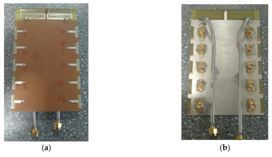
Figure 7.
MIMO system based on CMA: (a) top view; and (b) back view (Results from [68]).
5. Additional Effects of Decoupling Techniques
5.1. Analysis of External Decoupling
The external decoupling technique is the most commonly used method for isolation enhancement. Although it has an excellent performance in decoupling, it can be observed the additional effects and differences between various types of structures from the comparisons in Table 2.
Table 2.
Comparison among the referenced techniques of external decoupling.
The techniques mentioned above regarding external decoupling are summarized in Table 2. From Table 2, we can analyze the following four points to pay attention to when adopting external decoupling.
- The NLs and grounding branches maintain the compact MIMO size without destroying the completeness of the antenna substrate. The additional decoupling structures can be co-formed with antenna elements to demand the insufficient matching impedance and improve the effective length of the antenna. The height of the MIMO system is not increased by those metal lines with a low profile. However, it is displayed from simulation results that the bandwidth will become narrow due to the introduction of decoupling lines. This can be explained by the fact that decoupling lines can be equal to capacitance and inductance, which lead to a rise in resonant Q-value;
- To resist mutual coupling, the design of the PDE shape is innovative and versatile. In the role of added metal patches, the impedance mismatch of antenna arrays can be solved and the impedance bandwidth can be extended. Moreover, the antenna elements loaded parasitic patches typically exhibit good gain, which is attributed to the effective suppression of the currents flow by the decoupling structure. To obtain a strong decoupling effect, the ADS composed of parasitic patches is indirectly placed above the substrate, which will lead to an increase in the height of the antenna systems;
- The DGS can be etched with simple crafts and a low profile. Due to expanding the length of the current path by added slots, it can be seen the improvement of efficient bandwidth. The introduced slots with inductance will act as the resonator circuits at the operating frequency, so another resonance frequency will appear. Additionally, the matching impedance had almost no influence by the DGS of the background. Moreover, it has heat dissipation and is friendly to high power MIMO systems such as mm-wave arrays. However, the radiation patterns display a negative effect for the DGS that it will create undesired back radiation due to its defected shape. Additionally, the phenomenon of DGS simulation that the central frequency will shift to the lower point under the impact of the bandgap effect should be noticed;
- As for metamaterials, they can be found with more significant coupling reduction effects than other techniques due to the effective control of EM wave transmission by those human-made left-hand materials. The metamaterial array is also beneficial for gain enhancement. Some 3D structures are often adopted in metamaterials construction, which is complex and takes up more space for realizing the desirable refractive indices, such as the common mushroom shape of EBG. Moreover, a challenge in metamaterials design is overcoming the state of narrow bandwidth and high transmission power, so they and slots [70] or other structures are often combined for antenna performance improvement in practical applications.
As we can see, the advantages of external decoupling consist simplicity of conception and efficiency of completion. The properties of these decoupling techniques dictate that it is well suitable for planer MIMO systems. However, high isolation of the antenna array was achieved by adjusting the shape and position of the decoupling structure. Yet, there is a lack of a general and systematic approach to structural optimization, which makes the process of applying external decoupling time-consuming.
5.2. Analysis of Internal Decoupling
The internal decoupling techniques have also been well-established recently. The research focus on internal decoupling was concentrated on polarization diversity. Constructing orthogonal modes was a favored selection to ensure minimal correlation of different signals. The performances of these self-decoupling MIMO systems are given in Table 3.
Table 3.
Comparison among the referenced techniques of internal decoupling.
There are four additional effects brought by the internal decoupling application that deserve our attention:
- Due to polarization diversity, the internal decoupling can further increase the isolation level within a common radiation element. In addition to the significant decoupling result, multipath effects and fading can be effectively mitigated by polarization diversity. Thus, these self-decoupling MIMO systems exhibit strong multi-directional robustness compared to single-polarized systems in some scattering propagation environments [71], demonstrating it has great potential to deploy in massive MIMO for large scale wireless communication devices;
- Due to the absence of extra decoupling structures, on the one hand, the MIMO systems using internal decoupling can be allowed for smaller volume, which makes the integration with the communication devices frame become easy to realize, and space utilization is enhanced again. On the other hand, this approach that generating uncorrelated polarization modes by elaborately arranging antenna elements to ensure low isolation will not change the excepted radiation characteristics of the MIMO antenna array;
- It can be noticed that the popular polarization selection is to produce linear polarization (LP) waves in the exciting literature on internal decoupling. Although LP waves have better diversity characteristics, which benefit the directional propagation of the signal, the direction of the LP wave is easily deflected when reflections are encountered. Compared to the LP antenna, the received signals using circular polarization (CP) waves are more stable regardless of the antenna orientation [72]. The MIMO arrays with orthogonal circular polarization can be considered when the signal transmission environment is complicated, such as [73].
- The antenna element with different polarized radiation often works as a compact block. Thus, the potential of building multiple antenna arrays is exhibited. It is well known that the increase in the number of antenna array elements leads to the expansion of the ergodic channel capacity. By briefly copying antenna blocks having polarization diversity, the multi-antenna arrays are convenient to be obtained, which facilitates modular design during the construction of MIMO systems. Although the polarization diversity is sufficient for isolation enhancement, the surface current cannot be suppressed. Therefore, only selecting internal decoupling is not enough for MIMO systems.
It can be seen that the solutions of internal decoupling are more complicated compared to external decoupling in order to achieve the preferred decoupling effect in the application. The implementation of the diversity function on the common antenna element is the innovation point of this technique, so its antenna module with abundant components. However, the MIMO systems using internal decoupling have excellent performance in terms of integrity and compactness, which shows it is possible to develop in the MIMO decoupling field.
6. Conclusions and Discussion
Numerous investigations regarding isolation enhancement have been proposed. However, the properties and similarities between these decoupling techniques are in lack a specific analysis. In this review paper, a methodical and comprehensive summary about a variety of decoupling designs is presented. Some background knowledge about the mutual coupling effect is briefly reviewed in the former part of the article to provide a preparation for the technical analysis. Then, the state of the art used for coupling reduction is discussed in detail. Along with the discussed methods above, several additional effects brought by the adoption of decoupling techniques are concluded. Hence, the potential benefits and weaknesses of these techniques are revealed visually in an attempt to provide ideas for the future design of MIMO wireless systems in the field of 5G applications.
Although much work has been done to improve the isolation of MIMO antenna systems, the decoupling design of MIMO systems that combine high isolation and compact size still presents new challenges, and the potential work is as follows:
1. Hybrid decoupling structures
To solve coupling effects, several decoupling techniques were proposed. The various decoupling techniques mentioned above have different characteristics. Some are effective in suppressing the transmission of space waves, and some play a role in cutting off the flow of surface waves. However, the origin of the mutual coupling effect is not due to a single reason, which is the consequence of the combined action of multiple sources of radiation elements interference. Thus, the hybrid decoupling schemes that cooperate with decoupling techniques aimed at a wide range of interference paths can be considered for further isolation enhancement research. However, in the process of adopting hybrid deco upling schemes, it is hard to guarantee the stability of system complexity and power consumption. Consequently, it is prospective to try hybrid decoupling structures to attain decoupling breakthroughs while maintaining favorable MIMO performance.
2. Low complexity
It is a barrier that constructive complexity limits the practical application of decoupling techniques. To cover a wider bandwidth and enable high-isolation, coupling reduction designs are no longer satisfied with the basic forms of the decoupling structures, expanding to multiple branches or arranging decoupling elements into arrays. Nevertheless, the more decoupling structures integrated with the MIMO systems, the more complicated the device structures will be. Over the long term, it is not advisable to sacrifice physical space for a good degree of isolation. Other breakthroughs can be found, such as the use of new substrate materials. It was pointed out that the substrate dielectric constant and thickness also affect mutual coupling [74]. Besides the traditional ways in structure to suppress interactions, materials with low dielectric constants can be exploited to compensate for the spatial limitations on decoupling. In addition, it is notable for us that the application of MIMO in 5G portable devices. Modern portable devices aim for a large screen size percentage, metallic bezel carrying antenna system, and unreserved ground clearance. That means requirements of narrow metal bezel effect and extremely small volume of antenna elements should be considered, like literature [59,60,61]. Thus, keeping a balance between physical dimensions and decoupling performances of MIMO systems deserves investigating.
3. Systematic optimization procedure
Viewing conventional coupling reduction methods, most of these solutions strongly rely on the experience that engineers already had. Both the selection of the optimal decoupling point and the parameter adjustment of the decoupling structure have a lack general optimization procedures for the MIMO system. Nevertheless, shortcomings have been improving. For instance, the application of the CMA technique in decoupled design is mentioned above. These methods used for MIMO as a tool to solve for current characteristic modes and desired isolated radiation patterns can be calculated fast. In addition, some decoupling researches are also combined with algorithm optimization, which is also worthy of reference in the search for the optimal solutions of decoupling, such as MIMO isolation performance improvement based on genetic algorithm [75], optimization of ground length based on particle swarm algorithm (PSA) [76], optimization of antenna parameters and synthesizing beam patterns based on hybrid gravitational search algorithm and PSA [77]. Adopting these objective methods, the time consumed for decoupling optimization work can be substantially reduced compared to traditional operations. In the future, realizing the goal of automation and high efficiency during the decoupling optimization procedure is also the potential work for us.
It can be well defined that the development target of the MIMO decoupling issue: to achieve the highest isolation possible within a compact physical space. Although the experimental results of the above decoupling methods are satisfactory, the decision of decoupling schemes should be judged according to the features of MIMO systems and the transmission environment of the signal in reality. The realization of MIMO decoupling is not only an art of electronic design, but also a never-ending pursuit of high system performance of the current antenna field, and many possibilities and potentials are waiting to be explored. We hope that the analysis and discussion of MIMO decoupling techniques in this paper will inspire new thinking and look forward to more innovative and insightful approaches emerging in future 5G applications.
Author Contributions
K.D., Y.H. and Y.W. contributed to conceptualization, articulation, original draft preparation, review and the editing of the document. All authors have read and agreed to the published version of the manuscript.
Funding
This research received no external funding.
Institutional Review Board Statement
Not applicable.
Informed Consent Statement
Not applicable.
Data Availability Statement
Not applicable.
Conflicts of Interest
The authors declare no conflict of interest. The funders had no role in the design of the study; in the collection, analysis or interpretation of data; in the writing of the manuscript or in the decision to publish the results.
References
- Ezhilarasan, E.; Dinakaran, M. A Review on Mobile Technologies: 3G, 4G and 5G. In Proceedings of the 2017 Second International Conference on Recent Trends and Challenges in Computational Models, Tindivanam, India, 3–4 February 2017. [Google Scholar] [CrossRef]
- Beverage, H.H.; Peterson, H.O. Diversity Receiving System of R.C.A. Communications, Inc., for Radiotelegraphy. Proc. Inst. Radio Eng. 1931, 19, 529–561. [Google Scholar] [CrossRef]
- Peterson, H.O.; Beverage, H.H.; Moore, J.B. Diversity Telephone Receiving System of R.C.A. Communications, Inc. Proc. Inst. Radio Eng. 1931, 19, 562–584. [Google Scholar] [CrossRef]
- Jensen, M.A. A history of MIMO wireless communications. In Proceedings of the 2016 IEEE International Symposium on Antennas and Propagation (APSURSI), Fajardo, PR, USA, 26 June–1 July 2016. [Google Scholar] [CrossRef]
- Sengar, K.; Rani, N.; Singhal, A.; Sharma, D.; Verma, S.; Singh, T. Study and Capacity Evaluation of SISO, MISO and MIMO RF Wireless Communication Systems. Int. J. Eng. Trends Technol. 2014, 9, 436–440. [Google Scholar] [CrossRef] [Green Version]
- Moghe, S.; Upadhyay, R. Comparison of SISO and MIMO techniques in 802. In11n wireless local area network. In Proceedings of the 2009 International Conference on Emerging Trends in Electronic and Photonic Devices & Systems, Varanasi, India, 22–24 December 2009. [Google Scholar] [CrossRef]
- Foschini, G.J.; Gans, M.J. On Limits of Wireless Communications in a Fading Environment when Using Multiple Antennas. Wirel. Pers. Commun. 1998, 6, 311–335. [Google Scholar] [CrossRef]
- Li, J.; Zhang, X.; Wang, Z.; Chen, X.; Chen, J.; Li, Y.; Zhang, A. Dual-Band Eight-Antenna Array Design for MIMO Applications in 5G Mobile Terminals. IEEE Access 2019, 7, 71636–71644. [Google Scholar] [CrossRef]
- Qin, Z.; Geyi, W.; Zhang, M.; Wang, J. Printed eight-element MIMO system for compact and thin 5G mobile handest. Electron. Lett. 2016, 52, 416–418. [Google Scholar] [CrossRef]
- Li, Y.; Sim, C.; Luo, Y.; Yang, G. 12-Port 5G Massive MIMO Antenna Array in Sub-6GHz Mobile Handset for LTE Bands 42/43/46 Applications. IEEE Access 2018, 6, 344–354. [Google Scholar] [CrossRef]
- Wallace, J.W.; Jensen, M.A. Mutual coupling in MIMO wireless systems: A rigorous network theory analysis. IEEE Trans. Wirel. Commun. 2004, 3, 1317–1325. [Google Scholar] [CrossRef] [Green Version]
- Balanis, C.A. Antenna theory: A review. Proc. IEEE 1992, 80, 7–23. [Google Scholar] [CrossRef]
- Nikolic, M.M.; Djordjevic, A.R.; Nehorai, A. Microstrip antennas with suppressed radiation in horizontal directions and reduced coupling. IEEE Trans. Antennas Propag. 2005, 53, 3469–3476. [Google Scholar] [CrossRef]
- Wang, C.; Li, E.; Sievenpiper, D.F. Surface-Wave Coupling and Antenna Properties in Two Dimensions. IEEE Trans. Antennas Propag. 2017, 65, 5052–5060. [Google Scholar] [CrossRef] [Green Version]
- Chen, X.; Zhang, S.; Li, Q. A Review of Mutual Coupling in MIMO Systems. IEEE Access 2018, 6, 24706–24719. [Google Scholar] [CrossRef]
- Khayat, M.A.; Williams, J.T.; Jackson, D.R.; Long, S.A. Mutual coupling between reduced surface-wave microstrip antennas. IEEE Trans. Antennas Propag. 2000, 48, 1581–1593. [Google Scholar] [CrossRef]
- Lu, S.; Hui, H.T.; Bialkowski, M. Performance analysis of multiple-input multiple-output orthogonal frequency division multiplexing systems under the influence of antenna mutual coupling effect. IET Microw. Antennas Propag. 2009, 3, 288–295. [Google Scholar] [CrossRef] [Green Version]
- Lee, S.; Song, H. Accurate Statistical Model of Radiation Patterns in Analog Beamforming Including Random Error, Quantization Error, and Mutual Coupling. IEEE Trans. Antennas Propag. 2021, 69, 3886–3898. [Google Scholar] [CrossRef]
- Fletcher, P.N.; Dean, M.; Nix, A.R. Mutual coupling in multi-element array antennas and its influence on MIMO channel capacity. Electron. Lett. 2003, 39, 342–344. [Google Scholar] [CrossRef]
- He, Q.; Wang, B.; Shao, W. Radiation Pattern Calculation for Arbitrary Conformal Arrays that Include mutual-coupling effects. IEEE Antennas Propag. Mag. 2010, 52, 57–63. [Google Scholar] [CrossRef]
- Weiss, A.J.; Friedlander, B. Direction Finding in The Presence of Mutual Coupling. In Proceedings of the Twenty-Second Asilomar Conference on Signals, Systems and Computers, Pacific Grove, CA, USA, 31 October–2 November 1988. [Google Scholar] [CrossRef]
- Lui, H.; Hui, H.T. Direction-of-Arrival Estimation: Measurement using compact antenna arrays under the influence of mutual coupling. IEEE Antennas Propag. Mag. 2015, 57, 62–68. [Google Scholar] [CrossRef]
- Ye, Z.; Dai, J.; Xu, X.; Wu, X. DOA Estimation for Uniform Linear Array with Mutual Coupling. IEEE Trans. Aerospace Electron. Syst. 2009, 45, 280–288. [Google Scholar] [CrossRef]
- Janaswamy, R. Effect of element mutual coupling on the capacity of fixed length linear arrays. IEEE Antennas Wirel. Propag. Lett. 2002, 1, 157–160. [Google Scholar] [CrossRef]
- Abouda, A.A.; Hã Ggman, S.G. Effect of Mutual Coupling on Capacity of MIMO Wireless Channels in High SNR Scenario. Prog. Electromagn. Res. 2006, 65, 27–40. [Google Scholar] [CrossRef] [Green Version]
- Krusevac, S.M.; Kennedy, R.A.; Rapajic, P.B. Effect of Signal and Noise Mutual Coupling on MIMO Channel Capacity. Wirel. Pers. Commun. 2007, 40, 317–328. [Google Scholar] [CrossRef]
- Boris, S.B.; Robert, J.R.; Sanahuja, I.C. Exact representation of antenna system diversity performance from input parameter description. Electron. Lett. 2003, 39, 705–707. [Google Scholar] [CrossRef] [Green Version]
- Thaysen, J.; Jakobsen, K.B. Envelope correlation in (N,N) MIMO antenna array from scattering parameters. Microw. Opt. Technol. Lett. 2006, 48, 832–834. [Google Scholar] [CrossRef]
- Dama, Y.A.S.; Abd-Alhameed, R.A.; Zhou, D.; Jones, S.M.R.; Child, M.B.; Excell, P.S. Calculation of the spatial envelope correlation between two antennas in terms of the system scattering parameters including conducting losses. In Proceedings of the 2010 Loughborough Antennas & Propagation Conference, Loughborough, UK, 13 December 2010. [Google Scholar] [CrossRef]
- Sharawi, M.S.; Hassan, A.T.; Khan, M.U. Correlation coefficient calculations for MIMO antenna systems: A comparative study. Int. J. Microw. Wirel. Technol. 2017, 9, 1991–2004. [Google Scholar] [CrossRef]
- Diallo, A.; Luxey, C.; Le Thuc, P.; Staraj, R.; Kossiavas, G. Study and Reduction of the Mutual Coupling between Two Mobile Phone PIFAs Operating in the DCS1800 and UMTS Bands. IEEE Trans. Antennas Propag. 2006, 54, 3063–3074. [Google Scholar] [CrossRef]
- Du, C.; Zhao, Z.; Wang, X.; Yang, F. A Compact Cpw-Fed Triple-Band Mimo Antenna with Neutralization Line Decoupling for Wlan/Wimax/5g Applications. Prog. Electromagn. Res. M 2021, 103, 129–140. [Google Scholar] [CrossRef]
- Liu, R.; An, X.; Zheng, H.; Wang, M.; Gao, Z.; Li, E. Neutralization Line Decoupling Tri-Band Multiple-Input Multiple-Output Antenna Design. IEEE Access 2020, 8, 27018–27026. [Google Scholar] [CrossRef]
- Guo, J.; Cui, L.; Li, C.; Sun, B. Side-Edge Frame Printed Eight-Port Dual-Band Antenna Array for 5G Smartphone Applications. IEEE Trans. Antennas Propag. 2018, 66, 7412–7417. [Google Scholar] [CrossRef]
- Chen, S.; Wu, M.; Chiang, C.; Lin, M. 3.5-GHz four-element MIMO antenna system for 5G laptops with a large screen-to-body ratio. J. Electromagnet. Waves Appl. 2020, 34, 1195–1209. [Google Scholar] [CrossRef]
- Yang, M.; Zhou, J. A compact pattern diversity MIMO antenna with enhanced bandwidth and high-isolation characteristics for WLAN/5G/WiFi applications. Microw. Opt. Technol. Lett. 2020, 62, 2353–2364. [Google Scholar] [CrossRef]
- Yon, H.; Rahman, N.H.A.; Aris, M.A.; Jamaluddin, M.H.; Kong Cheh Lin, I.; Jumaat, H.; Mohd Redzwan, F.N.; Yamada, Y. Development of C-Shaped Parasitic MIMO Antennas for Mutual Coupling Reduction. Electronics 2021, 10, 2431. [Google Scholar] [CrossRef]
- Amin, F.; Saleem, R.; Shabbir, T.; Rehman, S.U.; Bilal, M.; Shafique, M.F. A Compact Quad-Element UWB-MIMO Antenna System with Parasitic Decoupling Mechanism. Appl. Sci. 2019, 9, 2371. [Google Scholar] [CrossRef] [Green Version]
- Li, M.; Cheung, S. A Novel Calculation-Based Parasitic Decoupling Technique for Increasing Isolation in Multiple-Element MIMO Antenna Arrays. IEEE Trans. Veh. Technol. 2021, 70, 446–458. [Google Scholar] [CrossRef]
- Wei, C.; Zhang, Z.; Wu, K. Phase Compensation for Decoupling of Large-Scale Staggered Dual-Polarized Dipole Array Antennas. IEEE Trans. Antennas Propag. 2020, 68, 2822–2831. [Google Scholar] [CrossRef]
- Deng, S.; Wang, Y.; Ding, J.; Chen, W.; Chen, C. Wideband Isolation Enhancement of Dual-Antenna Array Using Hybrid Decoupling Structures. In Proceedings of the 2020 International Symposium on Antennas and Propagation (ISAP), Osaka, Japan, 25–28 January 2021. [Google Scholar] [CrossRef]
- Venkateswara Rao, M.; Madhav, B.T.P.; Krishna, J.; Usha Devi, Y.; Anilkumar, T.; Prudhvi Nadh, B. CSRR-loaded T-shaped MIMO antenna for 5G cellular networks and vehicular communications. Int. J. RF Microw. Comput. Aided Eng. 2019, 29, e21799. [Google Scholar] [CrossRef]
- Chen, L.; Wang, D.; Zhang, S.; Xia, L.; Jiang, S.; Lan, S. A MIMO Antenna Array for 5G Mobile Terminals. In Proceedings of the 2019 IEEE International Symposium on Antennas and Propagation and USNC-URSI Radio Science Meeting, Atlanta, GA, USA, 7–12 July 2019. [Google Scholar] [CrossRef]
- Liu, Y.; Yang, X.; Jia, Y.; Guo, Y.J. A Low Correlation and Mutual Coupling MIMO Antenna. IEEE Access 2019, 7, 127384–127392. [Google Scholar] [CrossRef]
- Xing, H.; Wang, X.; Gao, Z.; An, X.; Zheng, H.; Wang, M.; Li, E. Efficient Isolation of an MIMO Antenna Using Defected Ground Structure. Electronics 2020, 9, 1265. [Google Scholar] [CrossRef]
- Khalid, M.; Naqvi, S.I.; Hussain, N.; Rahman, M.; Fawad; Mirjavadi, S.S.; Khan, M.J.; Amin, Y. 4-Port MIMO Antenna with Defected Ground Structure for 5G Millimeter Wave Applications. Electronics 2020, 9, 71. [Google Scholar] [CrossRef] [Green Version]
- Ren, Z.; Zhao, A.; Wu, S. MIMO Antenna with Compact Decoupled Antenna Pairs for 5G Mobile Terminals. IEEE Antennas Wirel. Propag. Lett. 2019, 18, 1367–1371. [Google Scholar] [CrossRef]
- Ren, Z.; Zhao, A. Dual-Band MIMO Antenna with Compact Self-Decoupled Antenna Pairs for 5G Mobile Applications. IEEE Access 2019, 7, 82288–82296. [Google Scholar] [CrossRef]
- Mathur, R.; Dwari, S. Compact planar reconfigurable UWB-MIMO antenna with on-demand worldwide interoperability for microwave access/wireless local area network rejection. IET Microw. Antennas Propag. 2019, 13, 1684–1689. [Google Scholar] [CrossRef]
- Yu, Z.; Wang, M.; Xie, Y. An improved loop ultra-wideband mimo antenna system for 5G mobile terminals. Prog. Electromagn. Res. Lett. 2020, 93, 99–106. [Google Scholar] [CrossRef]
- Hu, W.; Liu, X.; Gao, S.; Wen, L.; Qian, L.; Feng, T.; Xu, R.; Fei, P.; Liu, Y. Dual-Band Ten-Element MIMO Array Based on Dual-Mode IFAs for 5G Terminal Applications. IEEE Access 2019, 7, 178476–178485. [Google Scholar] [CrossRef]
- Smith, D.R.; Vier, D.C.; Koschny, T.; Soukoulis, C.M. Electromagnetic parameter retrieval from inhomogeneous metamaterials. Phys. Rev. E Stat. Nonlinear Soft Matter Phys. 2005, 71, 36617. [Google Scholar] [CrossRef] [Green Version]
- Dabas, T.; Gangwar, D.; Kanaujia, B.K.; Gautam, A.K. Mutual coupling reduction between elements of UWB MIMO antenna using small size uniplanar EBG exhibiting multiple stop bands. Int. J. Electron. Commun. 2018, 93, 32–38. [Google Scholar] [CrossRef]
- Ambika, A.; Tharini, C. Semicircle CSRR with Circular Slot Array Structures for High Level Mutual Coupling Reduction in MIMO Antenna. Prog. Electromagn. Res. M 2019, 87, 23–32. [Google Scholar] [CrossRef] [Green Version]
- Ishteyaq, I.; Masoodi, I.S.; Muzaffar, K. Eight-port double band printed Mimo antenna investigated for mutual-coupling and sar effects for sub-6 Ghz 5G mobile applications. Prog. Electromagn. Res. C 2021, 113, 111–122. [Google Scholar] [CrossRef]
- Li, M.; Zhong, B.G.; Cheung, S.W. Isolation Enhancement for MIMO Patch Antennas Using Near-Field Resonators as Coupling-Mode Transducers. IEEE Trans. Antennas Propag. 2019, 67, 755–764. [Google Scholar] [CrossRef]
- Rajeshkumar, V.; Rajkumar, R. SRR loaded compact tri-band MIMO Antenna for wlan/wimax applications. Prog. Electromagn. Res. Lett. 2021, 95, 43–53. [Google Scholar] [CrossRef]
- Chang, L.; Yu, Y.; Wei, K.; Wang, H. Polarization-Orthogonal Co-frequency Dual Antenna Pair Suitable for 5G MIMO Smartphone With Metallic Bezels. IEEE Trans. Antennas Propag. 2019, 67, 5212–5220. [Google Scholar] [CrossRef]
- Chang, L.; Yu, Y.; Wei, K.; Wang, H. Orthogonally Polarized Dual Antenna Pair with High Isolation and Balanced High Performance for 5G MIMO Smartphone. IEEE Trans. Antennas Propag. 2020, 68, 3487–3495. [Google Scholar] [CrossRef]
- Sun, L.; Li, Y.; Zhang, Z.; Feng, Z. Wideband 5G MIMO Antenna with Integrated Orthogonal-Mode Dual-Antenna Pairs for Metal-Rimmed Smartphones. IEEE Trans. Antennas Propag. 2020, 68, 2494–2503. [Google Scholar] [CrossRef]
- Li, M.; Xu, Z.; Ban, Y.; Sim, C.; Yu, Z. Eight-port orthogonally dual-polarised MIMO antennas using loop structures for 5G smartphone. IET Microw. Antennas Propag. 2017, 11, 1810–1816. [Google Scholar] [CrossRef]
- Li, M.; Ban, Y.; Xu, Z.; Guo, J.; Yu, Z. Tri-Polarized 12-Antenna MIMO Array for Future 5G Smartphone Applications. IEEE Access 2018, 6, 6160–6170. [Google Scholar] [CrossRef]
- Feng, B.; Chen, J.; Yin, S.; Sim, C.; Zhao, Z. A Tri-Polarized Antenna with Diverse Radiation Characteristics for 5G and V2X Communications. IEEE Trans. Veh. Technol. 2020, 69, 10115–10126. [Google Scholar] [CrossRef]
- Garbacz, R.J. Modal expansions for resonance scattering phenomena. Proc. IEEE 1965, 53, 856–864. [Google Scholar] [CrossRef]
- Zhao, X.; Yeo, S.P.; Ong, L.C. Planar UWB MIMO Antenna with Pattern Diversity and Isolation Improvement for Mobile Platform Based on the Theory of Characteristic Modes. IEEE Trans. Antennas Propag. 2018, 66, 420–425. [Google Scholar] [CrossRef]
- Kumar, N.; Khanna, R. A compact multi-band multi-input multi-output antenna for 4G/5G and IoT devices using theory of characteristic modes. Int. J. RF Microw. Comput. Aided Eng. 2019, 30, e22012. [Google Scholar] [CrossRef]
- Ganie, J.A.; Singh, C.; Jha, K.R.; Sharma, S.K. A LTE Band Integrated 5G Antenna Design using Characteristic Mode Analysis. In Proceedings of the 2019 IEEE International Symposium on Antennas and Propagation and USNC-URSI Radio Science Meeting, Atlanta, GA, USA, 7–12 July 2019. [Google Scholar] [CrossRef]
- Dong, J.; Wang, S.; Mo, J. Design of a Twelve-Port MIMO Antenna System for Multi-Mode 4G/5G Smartphone Applications Based on Characteristic Mode Analysis. IEEE Access 2020, 8, 90751–90759. [Google Scholar] [CrossRef]
- Hei, Y.; He, J.; Li, W. Wideband Decoupled 8-Element MIMO Antenna for 5G Mobile Terminal Applications. IEEE Antennas Wirel. Propag. Lett. 2021, 20, 1448–1452. [Google Scholar] [CrossRef]
- Ali, T.; Aw, M.S.; Biradar, R.C. A A Compact Bandwidth Enhanced Antenna Loaded with SRR For WLAN/WiMAX/Satellite Applications. Adv. Electromagn. 2018, 7, 78–84. [Google Scholar] [CrossRef]
- Sousa De Sena, A.; Benevides Da Costa, D.; Ding, Z.; Nardelli, P.H.J. Massive MIMO-NOMA Networks with Multi-Polarized Antennas. IEEE Trans. Wirel. Commun. 2019, 18, 5630–5642. [Google Scholar] [CrossRef]
- Dicandia, F.A.; Genovesi, S.; Monorchio, A. Analysis of the Performance Enhancement of MIMO Systems Employing Circular Polarization. IEEE Trans. Antennas Propag. 2017, 65, 4824–4835. [Google Scholar] [CrossRef]
- Chakraborty, S.; Rahman, M.A.; Hossain, M.A.; Mobashsher, A.T.; Nishiyama, E.; Toyoda, I. A 4-element MIMO antenna with orthogonal circular polarization for sub-6 GHz 5G cellular applications. SN Appl. Sci. 2020, 2, 1180. [Google Scholar] [CrossRef]
- Ozdemir, M.K.; Arvas, E.; Arslan, H. Dynamics of spatial correlation and implications on MIMO systems. IEEE Commun. Mag. 2004, 42, S14–S19. [Google Scholar] [CrossRef]
- Recioui, A.; Bentarzi, H. Genetic Algorithm Based MIMO Capacity Enhancement in Spatially Correlated Channels Including Mutual Coupling. Wirel. Pers. Commun. 2012, 63, 689–701. [Google Scholar] [CrossRef]
- Chouhan, S.; Panda, D.K.; Kushwah, V.S. Modified circular common element four-port multiple-input-multiple-output antenna using diagonal parasitic element. Int. J. RF Microw. Comput. Aided Eng. 2019, 29, e21527. [Google Scholar] [CrossRef]
- Mahmoud, K.R.; Montaser, A.M. Performance of Tri-Band Multi-Polarized Array Antenna for 5G Mobile Base Station Adopting Polarization and Directivity Control. IEEE Access 2018, 6, 8682–8694. [Google Scholar] [CrossRef]
Publisher’s Note: MDPI stays neutral with regard to jurisdictional claims in published maps and institutional affiliations. |
© 2022 by the authors. Licensee MDPI, Basel, Switzerland. This article is an open access article distributed under the terms and conditions of the Creative Commons Attribution (CC BY) license (https://creativecommons.org/licenses/by/4.0/).