Abstract
The integrated motor pump-jet (IMP) propulsion system is a form of modern underwater vehicle propulsion that uses a modular design paradigm. The integrated motor propulsor is a compact construction consisting of a permanent magnet (PM) and a pump-jet propulsor, as well as the propulsion and electrical systems. Compactness, great reliability, and low noise are the most significant features of this technology. The primary technology research status and main application configurations of propulsion devices with an integrated motor were examined based on the working principles and attributes of the devices. The theoretical and experimental research on the design, performance analysis, and control of IMPs is discussed, covering electric motors; bearing structures; hydrodynamic design; and hydrodynamic, electromagnetic, and bearing coupling design technology. This research investigates the most recent research goals, progress, and applications of IMPs, which includes their hydrodynamic performance, cavitation, and gap flow. Finally, the future essential technologies of high power, low vibration, water-lubricated bearings, electromagnetic and bearing coupling design, and IMP antipollution and antidamage capacity are summarized.
1. Introduction
An integrated motor pump-jet (IMP) is a propeller in which the motor stator is embedded in the pump-jet duct and the motor rotor is integrated with the tips of the pump-jet impeller blades rotating together at the same speed and in the same direction, with an air gap between the motor stator and rotor. It is a modern kind of underwater vehicle propulsion machine, corresponding to the modular design model, and consists of a propulsion system and an electrical system. The working principle of the IMP is that after energization, the motor air gap is opened into an air-gap magnetic field, and the current-carrying armature winding and the air-gap magnetic field interact to produce raw electromagnetic torque. The electromagnetic torque drives the motor rotor and, at the same time, drives the pump spray rotor circumferential rotation of the water work backward spray and the water flow to the pump spray axial reaction force to drive the propulsion carrier forward, which is used to ensure the rapidity of the propulsion carrier indicators.
The most important characteristics of this system are the compactness, high reliability, and low noise. This system could be directly driven by a high-power-density engine, specifically adapted to low noise, low vibration, and a finite volume as the main design goals of the underwater vehicle.
The core technical advantage of the pump-jet is the complete integration of the shaftless propulsion technology motor with the outstanding advantages of the pump-jet’s low noise and high critical speed, which allows the advantages of the pump-jet’s acoustic performance to be exploited while eliminating the shaft system’s acoustic excitation. At the same time, the transplantation of the propulsion motor from inside the boat to the interior of the thruster allows for a significant improvement in the effective use of space within the cabin. As with conventional pump-jets, the pump-jets can also be divided into two types: front-mounted stator shaftless pump-jets and rear-mounted stator shaftless pump-jets, depending on the axial position of the pump-jet stator blades in relation to the rotor blades.
In recent years, pump-jet thrusters (also known as pump-jets) have been widely used in underwater vehicles for their advantages such as their high propulsion efficiency, low radiation noise, strong anticavitation ability, and high critical speed [1], especially in submarines and torpedo propulsion. For example, the American “MK48” torpedo, the Seawolf-class submarine, the Virginia-class submarine, and the British Smart-class submarine all make use of this technology.
The propeller is attached to the shaft to drive the propulsion, while the opposite side of the shaft is put on the engine in conventional propulsion (Figure 1a). The main engine is located in the hull, so that the entire structure extends through the nacelle space. The bearings are installed on the stern with the middle circumferential and radial fixed shafts. In addition to this, it is necessary to decelerate the speed using a gearbox for the main propulsion device of a high-speed ship. When the underwater vehicle is operating, considerable frictional power loss, high levels of noise, and high levels of vibration may occur in the shafts, bearings, and gearboxes, etc.
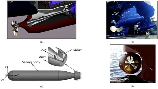
Figure 1.
Different marine propulsion systems: (a) conventional propulsion system; (b) podded propulsor; (c) pump-jet propulsion; and (d) shaftless IMP [3].
Since the 1990s, researchers have been interested in podded propulsion (Figure 1b), which is now a common design in the marine industry [1]. The pod propeller has a uniformly operated wake, low vibration, and low noise, and it can also provide thrust at multiple angles. Therefore, it plays the role of a rudder compared to the traditional propulsion method. Furthermore, it is beneficial to the interior of the engine room’s space layout, due to its flexible arrangements. A propeller, a bracket, and a pod make up the pod propeller, whereas the general propeller is a four-blade fixed-pitch propeller. Its downside is that an electric-driven motor is mounted in the pod, causing the diameter of the pod to be extremely large, reducing the propulsion efficiency even further [2]. The pump-jet propeller (Figure 1c) is usually composed of a pipe, a writing element (guide vane), and a rotor (impeller). Its working flow field is more complex, as it is an intricate multiconnected area compared to the internal flow field of the pump-jet blade and the open flow of the propeller, due to the existence of the pipe. The interaction between various components, the thruster, and the propulsion carrier affects the overall performance of the thruster.
The rapid development of today’s power electronics technology has subsequently promoted the birth of a new type of underwater propulsion device, the integrated motor propulsor (IMP), also known as the shaftless rim-driven propulsor/thruster (RDP/RDT) (Figure 1d). Yan et al. (2017) explained that this type of propeller is driven by the rim instead of by the shaft [3]. In the IMP propeller equipment, the drive motor is integrated into the structure, while the motor stator is embedded in the shield (pipe). The rotor is distributed on the rim or in the rim, and the propeller blades are directly connected to the rim. When the motor is operating, the blades follow the rotor, and they rotate together. The motor rotor and stator need to be equipped with sealing devices to prevent the entrance of water and various marine debris, because the propeller works underwater. Figure 2 shows three integrated motor thrusters with different structures. In Figure 2a,b, the structure is the same, the only difference being whether there is a hub between the two blades, which is evident in Figure 2b. As shown in Figure 2c, Cheng and He (2014) explained that, in addition to the hub, there are more guide vanes (rear spiral) behind the rotor [4]. The rotor blades generate thrust, while the guide vanes are used to eliminate the rotational movement of the liquid flow and play a role of diversion. A deceleration-type duct is used. Most of the ducts in the IMP thruster are of the decelerating type, which can achieve the effect of deceleration and pressurization to delay the generation of cavitation and achieve the purpose of noise reduction [5]. According to Wang et al. (2020), the IMP has several advantages compared to the conventional shaft-driven thruster, pod propulsor, and pump-jet propulsor [6]:
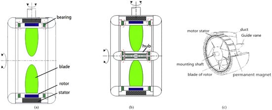
Figure 2.
Structural diagrams of (a) hubless RDT, (b) hub-type RDT, and (c) hub-type IMP [3,4].
- (1)
- The IMP thruster has a high degree of integration, and the cabin reduces the complicated propulsion drive shaft system, auxiliary components, propulsion motors, and other equipment into a compact structure with a light weight.
- (2)
- According to previous research, it has a low vibration and noise, since the motor and the propeller are integrated; the motor eliminates the noise in the split propulsion device when driving the propeller, and there is no longer any deceleration between the prime mover and the propeller transmission gear reduction gearbox, which is the main source of underwater radiation noise [7]. The back spiral stator eliminates the rotational movement of the fluid, reduces the flow velocity into the rotor blade, and increases the static pressure around the blade. The back spiral stator also delays the onset of cavitation at the tip of the blade and reduces the vortex cavitation noise, thus improving the invisibility.
- (3)
- It has a high propulsion efficiency, eliminating friction loss at the output shaft and improving the system propulsion efficiency. The back spiral stator can recover the rotational energy of the liquid flow by effectively increasing the propulsion energy. The IMP thruster is energized by the motor stator coil to generate a magnetic field, and the permanent-magnet motor rotor drives the impeller to rotate. Hence, there is no need to provide electricity to the magnetic field, which can eliminate the power loss of the magnetic field.
- (4)
- It has good operability and strong adaptability—due to the lack of intermediate transmission links, the reliability of the propeller transmission is improved. The pump flow does not change much at different speeds when it has already maintained a certain speed.
- (5)
- The entire system works in fluid, which can solve the heat-dissipation problem of the motor by cooling the motor and the bearing. This can also reduce the energy consumed by these cooling systems. Seawater can lubricate the bearings without oil lubrication, which is not only environmentally friendly but also eliminates the energy consumed by the lubrication system.
As a result, the emphasis of this study is on the advancement of IMP research in terms of theoretical and practical investigations into driven motor performance, motor control systems, hydrodynamic performance, and optimization. Within this study, future research directions are also offered.
2. Electric Motor and Control Technology
The IMP was first developed by the U.S. Naval Underwater Warfare Center in collaboration with the Applied Research Laboratory of Pennsylvania State University. Originally, it was used for unmanned submersibles. However, the motor was placed in the outer cover of the submersible; hence, the motor and the propulsion impeller were still two separate parts [8]. Then, the IMP was used for a light torpedo (Figure 3). The electric power which the light torpedo uses is an advanced lithium-ion battery and an integrated motor thruster. According to Qian and An (1997), this battery has a high energy density [9].
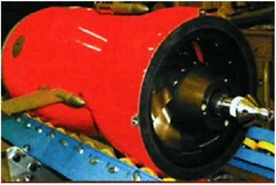
Figure 3.
Prototype of integrated motor propulsion developed by the U.S. Navy [8].
Figure 4 shows a schematic diagram of an IMP thruster. A hub, a duct, a motor stator, a rotor impeller with permanent magnets, and guiding vanes are the major components. The stator is supported by the outermost component, which is a duct similar to that of a pump-jet propeller. The stator of the motor is fixed in the outer pipe, and the outer ring of the rotor impeller is attached with permanent magnet pieces to the main shaft and can rotate around the shaft. The guide vane can be integrated with the shaft as a static blade cascade. Its function is to eliminate the rotational movement of the water sprayed from the back of the impeller so that it can effectively recover the energy of the sprayed water and balance the torque. When operating the motor, the stator coil of the motor is energized to generate a magnetic field. The impeller with permanent magnets rotates as the rotor of the motor. The blades pump water and discharge backward. The rotating energy is recovered by the stator blades, and the guide vanes are sprayed out through the nozzle to provide the device with forward momentum.
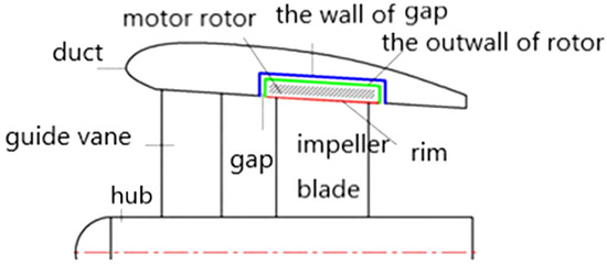
Figure 4.
Schematic diagram of integrated motor pump-jet thruster.
As mentioned above, when installing the IMP integrated motor, which is required to be as thin as possible in the radial direction and as short as possible in the axial direction to reduce the duct resistance, the electromagnetic air gap should be large enough to fill in the air gap of the internal stator/rotor anticorrosion sheath [10]. The first publicly disclosed integrated motor propulsion solution was a patent authorized by Luwig Kort, Hannover, Germany [10], as shown in Figure 5. The types of electric motors that are applicable to IMPs are reviewed in the following section to provide a clear overview and detailed summary of the controller of the IMP system (see Table 1).
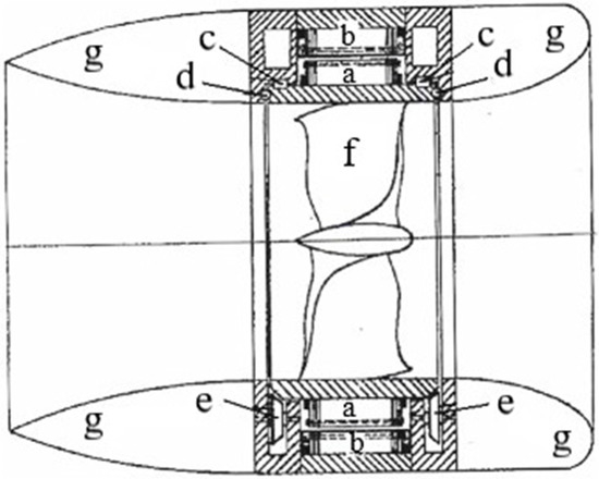
Figure 5.
The earliest patent of IMP: (a) rotor; (b) stator; (c) bearings; (d) bearings; (e) bearings and attachment; (f) propeller; and (g) duct [10].

Table 1.
Types of electric motors applicable to IMPs.
Traditional permanent-magnet synchronous motors generally use vector control. The control system needs to obtain accurate position information to control the speed and current of the motor. However, because the integrated motor propulsion device stops the rotating shaft, and traditional mechanical position sensors are difficult to install, position sensor control technology [11,12] is used quite often. The control scheme mainly has two technical routes: one is to obtain the rotor position based on the basic equations of the motor, which requires a high degree of accuracy regarding the motor parameters and does not perform well at low speeds; the other is to use the salient pole characteristics of the motor to extract the rotor position signal after injecting high-frequency signals [13]. This method can also achieve better estimation results in the low-speed and zero-speed range. However, it is not suitable for surface-mount motors with a low salient pole rate, and the algorithm is more complicated. It should be pointed out that the unsteady pulse power and jitter generated by the rotation of the integrated motor propeller blades in the water flow can be directly transmitted to the motor rotor through the integrated rotating structure, which causes the fluctuation of the motor torque. In addition, the integrated motor’s low speed, frequent starting, high acceleration and deceleration dynamic performance, and high system operation noise requirements make its position sensorless control more difficult, and it is also one of the key technologies that restrict the development of high-performance shaftless propellers. Hence, for the high-performance control requirements of integrated motors, new integrated position-sensing technologies can also be explored in the overall plan.
3. IMP Bearing and Hydrodynamic Design
3.1. Bearings Used in IMPs
The open structure of the integrated motor propeller requires its bearings to be able to operate in a seawater environment. If a nonaqueous lubricant is used for the bearing, a sealing device is required, which increases the difficulty, complexity, and cost of the entire system and is likely to cause water pollution. The use of water-lubricated bearings can reduce the weight and complexity of the integrated motor thruster system and better reflect the advantages of the integrated motor thruster. The suitable bearing arrangement is determined according to the application characteristics and use requirements of the device. The bearings can be arranged either on the hub or rim or in a mixed arrangement (Figure 6). To obtain a good hydrodynamic performance from the IMP propeller, the thickness of the duct and the diameter of the hub must be as small as possible, which leads to the complexity of the bearing design.
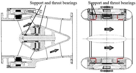
Figure 6.
The location of the bearings in an IMP [10].
The research work on water-lubricated bearings started earlier in countries with developed shipbuilding industries, such as the United States, Canada, Japan, Australia, and the United Kingdom. As early as the 1940s, there are records of American ships using water-lubricated bearings. After years of development, some companies have formed a series of water-lubricated bearing products suitable for various working conditions, such as the Thordon bearing series [31], the Perform bearing series [32] of the British TENMAT company, the water-lubricated bearing material of the British Countrose company [33], the American Duramax Marine Johnson Cutless water-lubricated bearing series [34], and the water-lubricated bearing series of BFGoodrich and Johnson Rubber (Figure 7). The types of bearing suitable for IMPs are covered in this section to provide a clear picture and complete explanation of the IMP system’s controller (see Table 2).
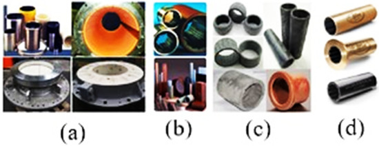
Figure 7.
(a) Thordon bearing of Thomson–Gordon, (b) water-lubricated bearing material of Countrose, (c) Feroform bearing of TENMAT, (d) Johnson Cutless bearing of Duramax Marine [35].
Table 2.
Types of bearings applicable to IMP.
3.2. Hydrodynamic Design
3.2.1. Hydrodynamic Performance
The hydrodynamic performance of an IMP thruster is the key to ensuring its thrust and power index, which directly affect the propulsion efficiency, vibration, and noise. With the continuous development of computer technology, numerical testing has gradually become an important means of keeping pace with and complementing physical testing in the research and development of the hydrodynamic performance of propulsion devices, as well as effectively promoting the research and development of propulsion devices in general. It is critical to match propeller hydrodynamic characteristics to specific factors to achieve efficient IMP. The most significant metric is the propeller pitch ratio. The hydrodynamic efficiency is further affected by the propeller’s structural design, the form and size of the duct, the air-gap thickness, and other parameters. Computational analyses and experimental research on some IMP parameters are presented in this section to provide a clear picture and detailed explanation of IMP thrusters’ hydrodynamic performance (see Table 3).
Table 3.
Summary of numerical studies on the hydrodynamic performance of IMP thrusters.
3.2.2. Cavitation
Cavitation is a very important hydrodynamic phenomenon that occurs in IMPs and causes severe vibration, noise, material damage, and other problems. Consequently, cavitation in IMPs has piqued our interest throughout the years. Few scholars have summarized the related papers to boost research on cavitation in IMPs. Turbulence is involved in the majority of cavitation occurrences. Both the cavitation model and the turbulence-modeling approach influence the numerical accuracy of cavitating turbulent flow simulations. The latest advances in the study of cavitation in IMPs are reviewed in this section to provide a clear picture and detailed explanation of the methods for cavitation modeling as well as the accomplishments based on IMP thruster numerical simulations (see Table 4).
Table 4.
Summary of methods for cavitation simulation and the achievements based on numerical calculations for IMP thrusters.
3.2.3. Gap Flow
The main structural difference between an IMP and a traditional pump-jet propulsor is that the motor is located in the duct, and the motor rotor is seamlessly coupled to the impeller blade surface. The stator is also installed in the duct. This structure gives it the advantages of flexibility, high reliability, a compact structure, low vibration, and low noise. The structure of an IMP includes a gap between the inner surface of the stator of the motor and the outer surface of the rotor. When the propeller is working and water flows through the gap, it can not only cool the heat-generating parts, such as the stator of the motor, but to a certain extent, due to the viscosity and density of the water and air, it will produce a large friction torque at the connection point (motor rim) between the motor rotor and the impeller blade, which will cause the propeller to experience a large power loss when rotating at a high speed. Therefore, to design IMP thrusters with low power loss and good heat dissipation performance, it is necessary to study the gap-flow law. To acquire a clear picture and detailed explanation of the effect of the gap-flow model on the hydrodynamic performance of IMP thrusters, the numerical studies and experimental research on the IMP gap are discussed in this section (see Table 5).
Table 5.
Summary of the effect of the gap-flow model on the hydrodynamic performance of IMP thrusters.
4. Dynamic Coupling Technology
4.1. Dynamic Coupling between IMPs and Ship Hulls
The interaction of a yacht’s duct and hull was investigated by Voith (2017) [39]. Figure 8a depicts the RDT installation, while Figure 8b depicts the water flow pattern (b). Between the propeller and the hull, this configuration created a flow vortex and negative pressure.
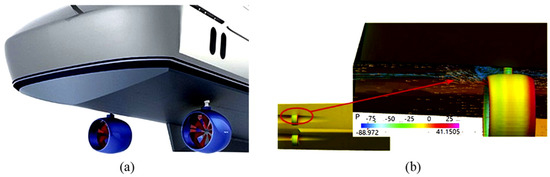
Figure 8.
Interaction between duct and hull of a yacht: (a) yacht equipped with two RDTs; (b) water flow pattern behind the RDT [39].
To optimize the structure and installation site of RDTs, it is critical to comprehend the interaction and nonlinear coupling between the wakefield, the RDT, and the hull. The efficiency of the system can be improved while minimizing sailing resistance by optimizing the RDT design, hull lines, and installation sites. To study the interactions between the hull and RDTs, Lu et al. (2014) [82] investigated the influence of the number of RDTs (either two or four sets) and the location of the RDT installation on the hydrodynamic performances of an underwater vehicle (Figure 9). Due to the influence of the stern wake, reducing the distance between the RDT and the hull improved the RDT’s efficiency and the thrust deduction factor. To increase the vehicle’s hydrodynamic performance, the RDTs could be placed at the parallel middle body towards the aft body. This would result in a negative thrust deduction factor. When RDTs were installed on the stern planes, increasing the number of RDTs resulted in a significant reduction in the total propulsive efficiency; however, when the RDTs were mounted on the parallel middle body, there was only a small reduction in the total propulsive efficiency. The design, integration, and testing of a steerable rim-driven thruster for the short takeoff aviation support ship (STASS) model was the subject of Newacheck et al. (2019) [83]. To analyze the influence of the newly designed and integrated system on the drag force, the testing matrix used four configurations of the bare hull, supplemented with SHIPS, bollard pull, and self-propelled phases. The drag force for SHIPS was found to be enhanced by 20% due to a variety of factors, including the increased wetted surface area and the blocking effect caused by the presence of the motor cage and steering column in the flow direction. After the thruster was integrated, there was a further increase in the drag force.
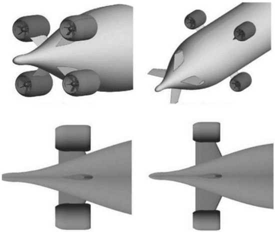
Figure 9.
Different numbers and installation locations of RDTs [82].
4.2. The Coupling Design Technology of Hydrodynamics, Electromagnetics, and Bearings
Numerical simulation methods also play an irreplaceable role in analyzing the coupling effects of the electromagnetic–hydrodynamic–thermal structure of the integrated motor propulsion devices, according to Hu et al. (2016) [84,85] and Shen et al. (2016) [29]. To tackle the heat dissipation problem of permanent-magnet motors, slots are positioned at the front and rear ends of the motor rotor to facilitate communication with the air gap between the stator and rotor. Figure 10 depicts the design and simulation of a natural circulation seawater cooling method.
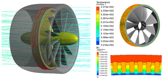
Figure 10.
Multifield simulation of IMP [85].
Liang et al. (2012) used a combination of the finite element method and the finite volume method to carry out the study of electromagnetic–thermal coupling [86,87]. The back electromotive force and temperature were measured in this study through experiments to demonstrate that the integrated permanent magnet can improve the effectiveness of the motor-cooling system, as illustrated in Figure 11 and Figure 12.
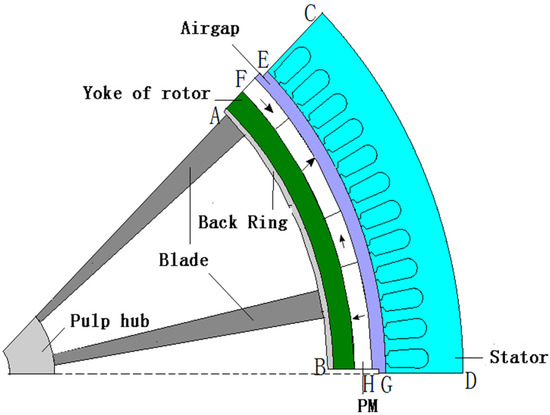
Figure 11.
Simplified PM model for multifield coupled analysis [86].
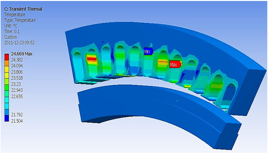
Figure 12.
Temperature distribution of stator and windings [86].
5. Discussion
5.1. The Design of the IMP
The lifting-line theory has significantly promoted the development of IMP propeller design technology. Many researchers have proposed a corresponding design theory, mainly focused on the design method and design object. In terms of design methods, the IMP propeller lifting-line theory was improved because of the defects of the heavy-duty propeller and the basic design theory under nondesign conditions. For IMP propellers with a side slope and pitch, the corresponding lifting-line design method is perfected. In recent years, scholars have combined the IMP propeller lifting-line theory with the panel method and the Reynolds-averaged Navier–Stokes (RANS) method to improve the accuracy and efficiency of IMP propeller performance prediction. In addition, it is combined with modern optimization design theory, and the performance optimization of an IMP propeller is considered in the design stage, which improves the design efficiency. In terms of the design objects, as the calculation speed increases, the lifting-line theory can be applied to the performance prediction and design of complex thrusters.
The lifting-surface method is used by many studies to deal with the forward prediction of IMP propellers. The current research focuses include the shrinkage and curling of the wake vortex in the transition zone of the IMP propeller and the tip vortex separation model, which considers the trim and side slope, etc., establishing a model of the IMP propeller trailing vortex and tip vortex, and the separation vortex of the leading edge and corresponding improvement methods are also proposed. In addition, when the IMP propeller interacts with other components, the influence of the hub and the coupling panel method are introduced to consider the influence of other components to improve the accuracy of the performance prediction. Regarding the inverse problem of the lifting-surface design method, since the shape of the blade profile is closely related to its load form, efficiency, cavitation, and other hydrodynamic properties, the main research focus is the precise and rapid design of the vortex grid method to meet the given lift distribution, the design of the arcuate surface of the blade arch under the circulation distribution, and the three-dimensional refinement of the theoretical boundary value problem of the IMP propeller lifting surface. In addition, when considering the interaction between the hull and its appendages, ducts, and propellers, the lifting surface is coupled with other theories such as RANS for design, and the influence of other components is more accurately considered in the design stage to further improve the design accuracy and efficiency.
At present, the lifting-line model is relatively mature and can solve the problems related to the calculation of the propeller thrust, torque, efficiency, and induced speed field behind the propeller; the calculation time required is relatively short, but it has certain limitations. Compared with the lifting-line method, whether it is a forward prediction problem or a reverse design problem, the lifting-surface method can fully consider the blade chord length, camber, and pitch distribution, which has great advantages. Regarding IMP propeller design issues, most of the past studies have focused on the deformation of the tail vortex, the effect of the hub, and the related lifting-surface design of the profile load distribution. It is particularly important to refine the design of some special propellers, such as ducted propellers and pump-jet propellers, to couple the lifting-line and lifting surface design methods with methods such as the surface element method or RANS, and to consider the interaction of the components. This aspect is worthy of further study.
5.2. Hydrodynamic Performance of IMP Thrusters
When predicting the propulsion performance of an IMP thruster, the CFD method considering the viscous effect can accurately simulate the complex flow of the IMP thruster’s wakefield and the slight vortex structure of the blade. At the same time, it can accurately simulate the flow near the wall through the boundary layer grid, and the effect of turbulent flow is fully considered on the propulsion performance of IMP thrusters. With the development of high-performance computers, the viscous-flow CFD method strongly supports the prediction of the hydrodynamic performance of IMP thrusters. At present, it seems to be the most mainstream method for the numerical simulation of IMP thrusters’ flow fields.
In terms of CFD preprocessing for IMP thrusters, the CFD grid discrete method is relatively mature. The main research work is focused on comparing different grid types and corresponding grid layout methods to automatically generate grids for specific calculation conditions and to investigate the combined use of different grid discretization methods.
In terms of the IMP thruster CFD calculation method, the aim is to evaluate the applicability of different turbulence models in the calculation of an IMP thruster’s hydrodynamic performance. At present, it seems that different turbulence models have certain differences when measuring the hydrodynamic performance of IMP thrusters. These works also provide a reliable reference for the reasonable selection of turbulence models that are suitable for specific research topics. For the flow field of rotating machinery such as IMP thrusters, numerical methods such as multireference system models, sliding grids, overlapping grids, moving grids, and periodic boundaries also have corresponding suitable application scenarios.
In terms of CFD calculations for IMP thrusters, the current research work is mainly focused on the open-water performance of IMP thrusters, the numerical prediction of unsteady forces, the fluid–structure interaction, the performance in a nonuniform flow field, and the cavitation of IMP thrusters. Regarding the open-water performance, the research content includes the impact analysis of IMP thruster parameters, such as side slope and pitch, and the geometric parameters of duct IMP thrusters, such as blade tip clearance. For the application of different turbulence models in the calculation of the unsteady force of IMP thrusters, more extensive research has been carried out at home and abroad, mainly comparing the calculation accuracy of different turbulence models. According to the research results, the DES method and the LES method deal with nonstationary forces and are most widely used for steady problems. There are also related studies on the influence of calculation settings on unsteady calculations and the calculation of the unsteady performance of new types of thrusters.
5.3. Optimization Technology of IMP Thrusters
Previous studies pay more attention to the design goals of IMP propulsion efficiency, cavitation performance, blade strength, and noise performance. The introduction of multiobjective optimization design methods is aimed at the occasions that require multiple performance indicators. Generally, more multiobjective methods are being used, such as the dualobjective optimization design of propulsion efficiency and cavitation performance, and performance optimization under multiple operating conditions.
During the optimization design process of IMP propellers, many scholars have analyzed the sensitivity of IMP propeller design parameters to design goals through design of experiment (DOE), Sobol sensitivity analysis, and regression analysis. Studies have shown that the maximum chord length of the blade is the main factor affecting the cavitation performance, and the dimensionless radius of 0.7–0.9 has a greater impact on the low-frequency broadband noise of the IMP propeller. In addition, the thinner the blade, the more obvious the effect of improving the efficiency of the propeller, but thinner blades have an adverse effect on the strength and other mechanical properties of the blade. The influence of the parameters of IMP propellers on the performance and the restrictive relationships between the parameters are more easily reflected in the optimization design process. It is very important to apply modern optimization design theory to IMP propeller design optimization.
6. Conclusions
This paper analyzes the IMP thruster’s working structure, major structural application technology, current hydrodynamic performance research, and important technologies that require further resolution. The IMP thruster completely embraces the principle of extensive electric modularization and integration, better reflecting the high power density, high efficiency, low radiation noise, and maneuverability of electric propulsion systems. As a result, integrated motor propulsion technology has gradually expanded its application areas to other rotating machinery such as pumps, turbines, and fans. However, there are still some uncertain issues with IMP thrusters, for example, that the output power is still in the megawatt range due to power loss at the intake. Furthermore, using IMPs in shallow water, especially around gravel, is exceedingly risky. To design an IMP, numerous critical technologies must be resolved. Because the stator of the motor in the IMP propeller is embedded in the duct, the rotor and the impeller blade are seamlessly connected. This structure thickens the duct and affects the entire flow field. In addition, it is necessary to ensure that the propeller motor has a large enough flow area by limiting the thickness of the stator yoke, rotor yoke, and the magnet of the motor. If the size is too thin, the electromagnetic field will saturate prematurely, further reducing the magnetic flux density of the motor, causing the motor to fail to work normally. In addition, as the IMP thruster eliminates the use of the drive shaft, bearings, and vibration isolation devices that support the traditional motor and reduce the internal noise of the hull, the thrust and torque generated by the thruster are directly coupled with the electromagnetic excitation force generated by the motor, which then increases the electromagnetic noise, hydrodynamic noise, etc. Therefore, the complexity and necessity of designing a high-power, low-vibration, low-noise, and high-performance motor are increased.
If a nonaqueous lubricant is used for bearing lubrication, then the sealing devices must be considered. This will increase the complexity and design cost of the entire IMP propeller structure and, at the same time, may cause some other marine pollution problems. Therefore, the use of water-lubricated bearings can reduce the weight and complexity of the IMP thruster system to better reflect the advantages of the IMP thruster. However, due to the low viscosity of the water medium, the bearing capacity of the water film is not large enough, which means that the water-lubricated bearings experience a mixed-lubrication state. As a result, this will affect the bearing capacity and working performance of the bearing. In addition, the adaptability of the bearing material to water and the influence of different flow conditions on the dynamic pressure lubrication characteristics of the bearing will affect the load transfer in the bearing. Therefore, the load-bearing reliability characteristics and design optimization of the bearing should consider the above-mentioned series of issues. To obtain an IMP thruster with a high propulsion efficiency and high output power, the design method for these components must be very strict, because the degree of coupling between high-power thruster components must be higher. Therefore, hydrodynamic–electromagnetic–thermal–fluid–solid coupling research can effectively help us to understand the complex working conditions of the coupling between the internal components and the whole of the IMP thruster. Additionally, it can obtain the key influencing factors that affect the propulsion performance, which will provide technical support for the design of high-power IMP thrusters in the future.
When the IMP propeller is working, as it is completely immersed in seawater, all impurities in the seawater will be sucked into the air gap of the propeller, which will then reduce the amount of flowing fluid in the air gap, affecting the cooling of the motor and ultimately reducing the efficiency of the motor. When the IMP is operating in shallow waters, especially in sandy waters, the motor may be directly damaged. The failure of the motor will cause the ship to lose power. Therefore, improving the antipollution and antidamage abilities of IMP thrusters is of great significance for improving the hydrodynamic performance and efficiency of the thrusters.
Author Contributions
Q.L. and S.A. drafted the manuscript; Q.L., S.A. and M.R.M.R. provided advice regarding revision of the manuscript. All authors have read and agreed to the published version of the manuscript.
Funding
This work was supported by Department of Mechanical and Manufacturing Engineering, the Faculty of Engineering and Built Environment, Universiti Kebangsaan Malaysia (UKM)There is no funding source, and in paert the Project of Young Innovative Talents in General Universities of Guangdong Province (Natural Science Category) (2020KQNCX112); and Guangdong Technology College, the department of Intelligent Manufacturing for their support this research.
Institutional Review Board Statement
Not applicable.
Informed Consent Statement
Informed consent was obtained from all individual participants included in the study.
Data Availability Statement
Not applicable.
Acknowledgments
The authors would like to thank the Project of Young Innovative Talents in General Universities of Guangdong Province (Natural Science Category) (2020KQNCX112); and Guangdong Technology College, the department of Intelligent Manufacturing for their support this research.
Conflicts of Interest
The authors declare that they have no conflict of interest.
Nomenclature
| Thrust coefficient | Vorticity | ||
| Torque coefficient | Cavitation number | ||
| Propulsion efficiency, | Pressure coefficient | ||
| Advance coefficient, | Gap moment coefficient | ||
| Inflow velocity | |||
| Rotational speed | |||
| Diameter of propeller |
References
- Shamsi, R.; Ghassemi, H.; Molyneux, D.; Liu, P. Numerical hydrodynamic evaluation of propeller (with hub taper) and podded drive in azimuthing conditions. Ocean. Eng. 2014, 76, 121–135. [Google Scholar] [CrossRef]
- Liu, B.; Vanierschot, M. Numerical Study of the Hydrodynamic Characteristics Comparison between a Ducted Propeller and a Rim-Driven Thruster. Appl. Sci. 2021, 11, 4919. [Google Scholar] [CrossRef]
- Yan, X.; Liang, X.; Ouyang, W.; Liu, Z.; Liu, B.; Lan, J. A review of progress and applications of ship shaft-less rim-driven thrusters. Ocean. Eng. 2017, 144, 142–156. [Google Scholar] [CrossRef]
- Cheng, P.; He, B. Investigate the Application of Integrated Motor Water-Jet Propulsor on ROV. Guangdong Shipbuild. 2014, 33, 50–125. [Google Scholar]
- Othman, N.; Kamarudin, S.; Takriff, M.; Rosli, M.; Engku Chik, E.; Meor Adnan, M. Optimization of a continuous hybrid impeller mixer via computational fluid dynamics. Sci. World J. 2014, 2014, 1–6. [Google Scholar] [CrossRef]
- Amiruddin, H.; Mahmood, W.M.F.W.; Abdullah, S.; Mansor, M.R.A.; Mamat, R.; Alias, A. Application of Taguchi method in optimization of design parameter for turbocharger vaned diffuser. Ind. Lubr. Tribol. 2017, 69, 409–413. [Google Scholar] [CrossRef]
- Wang, H.-G. Study of vibration isolation and noise reduction technology in US nuclear submarine propulsion system. Ship Sci. Technol. 2013, 35, 149–153. [Google Scholar]
- Tenconi, A.; Profumo, F.; Bauer, S.E.; Hennen, M.D. Temperatures evaluation in an integrated motor drive for traction applications. IEEE Trans. Ind. Electron. 2008, 55, 3619–3626. [Google Scholar] [CrossRef]
- Qian, D.; An, B. Permanent magnet motor-pump integrated system: Feasibility study of a novel motor-pump integrated system for underwater carriers. J. Unmanned Undersea Syst. 1997, 5, 35–43. [Google Scholar]
- Lai, S.H. Design Optimisation of a Slotless Brushless Permanent Magnet DC Motor with Helically-Wound Laminations for Underwater Rim-Driven Thrusters. Ph.D. Thesis, University of Southampton, Southampton, UK, 2006. [Google Scholar]
- Batzel, T.D.; Lee, K.Y. Slotless permanent magnet synchronous motor operation without a high resolution rotor angle sensor. IEEE Trans. Energy Convers. 2000, 15, 366–371. [Google Scholar] [CrossRef]
- Batzel, T.D.; Thivierge, D.P.; Lee, K.Y. Application of sensorless electric drive to unmanned undersea vehicle propulsion. IFAC Proc. Vol. 2002, 35, 307–312. [Google Scholar] [CrossRef]
- Zhu, Z.-Q.; Gong, L. Investigation of effectiveness of sensorless operation in carrier-signal-injection-based sensorless-control methods. IEEE Trans. Ind. Electron. 2010, 58, 3431–3439. [Google Scholar] [CrossRef]
- Taylor, O.S.; Repp, J.R.; Brown, D.W. Submersible Electric Propulsion Motor with Propeller Integrated Concentrically with Motor Rotor. U.S. Patent 4831297, 16 May 1989. [Google Scholar]
- Brown, D. Submersible Outboard Electric MotorPropulsor. Nav. Eng. J. 1989, 101, 44–52. [Google Scholar] [CrossRef]
- Tuohy, P.; Smith, A.; Husband, M. Induction rim-drive for a marine propulsor. In Proceedings of the 5th IET International Conference on Power Electronics, Machines and Drives, Brighton, UK, 19–21 April 2010. [Google Scholar]
- Tuohy, P. Development of Canned Line-Start Rim-Driven Electric Machines. Ph.D. Thesis, The University of Manchester, Manchester, UK, 2011. [Google Scholar]
- Tuohy, P.M.; Smith, A.C.; Husband, M.; Hopewell, P. Rim-drive marine thruster using a multiple-can induction motor. IET Electr. Power Appl. 2013, 7, 557–565. [Google Scholar] [CrossRef]
- Richardson, K.; Pollock, C.; Flower, J. Design of a switched reluctance sector motor for an integrated motor/propeller unit. In Proceedings of the 1995 Seventh International Conference on Electrical Machines and Drives, Durham, UK, 11–13 September 1995. [Google Scholar]
- Abu Sharkh, S.; Turnock, S.; Draper, G. Performance of a tip-driven electric thruster for unmanned underwater vehicles. In Proceedings of the Eleventh International Offshore and Polar Engineering Conference, Stavanger, Norway, 17–22 June 2001. [Google Scholar]
- Sharkh, S.A.; Lai, S.H.; Turnock, S. Structurally integrated brushless PM motor for miniature propeller thrusters. IEE Proc. Electr. Power Appl. 2004, 151, 513–519. [Google Scholar] [CrossRef]
- Pashias, C.; Turnock, S. Hydrodynamic Design of a bi-Directional, Rim-Driven Ducted Thruster Suitable for Underwater Vehicles; University of Southampton: Southampton, UK, 2003. [Google Scholar]
- Pashias, C.; Turnock, S.; Abu Sharkh, S. Design optimization of a bi-directional integrated thruster. In Proceedings of the SNAME 10th Propeller and Shafting Symposium, Virginia Beach, VA, USA, 17 September 2003. [Google Scholar]
- Van Dine, P. Manufacture of a prototype advanced permanent magnet motor pod. J. Ship Prod. 2003, 19, 91–97. [Google Scholar] [CrossRef]
- Krøvel, Ø.; Nilssen, R.; Skaar, S.; Løvli, E.; Sandoy, N. Design of an integrated 100 kW permanent magnet synchronous machine in a prototype thruster for ship propulsion. CD Rom Proc. ICEM 2004, 2004, 117–118. [Google Scholar]
- Sharkh, S.; Lai, S. Design optimization of a slotless PM brushless motor with helical edge wound laminations for rim driven thrusters. High Technol. Lett. 2010, 16, 70–79. [Google Scholar]
- Cheng, B.; Pan, G.; Cao, Y. Analytical design of the integrated motor used in a hubless rim-driven propulsor. IET Electr. Power Appl. 2019, 13, 1255–1262. [Google Scholar] [CrossRef]
- Liang, J.; Zhang, X.; Qiao, M.; Zhu, P.; Cai, W.; Xia, Y.; Li, G. Optimal design and multifield coupling analysis of propelling motor used in a novel integrated motor propeller. IEEE Trans. Magn. 2013, 49, 5742–5748. [Google Scholar] [CrossRef]
- Shen, Y.; Hu, P.; Jin, S.; Wei, Y.; Lan, R.; Zhuang, S.; Zhu, H.; Cheng, S.; Chen, J.; Wang, D. Design of novel shaftless pump-jet propulsor for multi-purpose long-range and high-speed autonomous underwater vehicle. IEEE Trans. Magn. 2016, 52, 1–4. [Google Scholar] [CrossRef]
- Hassannia, A.; Darabi, A. Design and performance analysis of superconducting rim-driven synchronous motors for marine propulsion. IEEE Trans. Appl. Supercond. 2013, 24, 40–46. [Google Scholar] [CrossRef]
- Ruusila, V.; Nyyssönen, T.; Kallio, M.; Vuorinen, P.; Lehtovaara, A.; Valtonen, K.; Kuokkala, V. The effect of microstructure and lead content on the tribological properties of bearing alloys. Proc. Inst. Mech. Eng. Part J J. Eng. Tribol. 2013, 227, 878–887. [Google Scholar] [CrossRef]
- Salama, M. The effect of macro-roughness on the performance of parallel thrust bearings. Proc. Inst. Mech. Eng. 1950, 163, 149–161. [Google Scholar] [CrossRef]
- Simmons, J.; Knox, R.; Moss, W. The development of PTFE (polytetrafluoroethylene)-faced hydrodynamic thrust bearings for hydrogenerator application in the United Kingdom. Proc. Inst. Mech. Eng. Part J J. Eng. Tribol. 1998, 212, 345–352. [Google Scholar] [CrossRef]
- Bin, S.; Sun, F.-H.; Zhang, Z.-M.; Shen, H.-S.; Guo, S.-S. Application of ultra-smooth composite diamond film coated WC–Co drawing dies under water-lubricating conditions. Trans. Nonferrous Met. Soc. China 2013, 23, 161–169. [Google Scholar]
- Zhang, X.L. Research on Load-Bearing Characteristics and Structural Design of Water-Lubricated Bearings for Integrated Motor Propulsion. Master’s Thesis, Shanghai Jiaotong University, Shanghai, China, 2017. [Google Scholar]
- Kennedy, G.C.; Holt, J.K. Developing a high efficiency means of propulsion for underwater vehicles. In Proceedings of the Southcon′95, Fort Lauderdale, FL, USA, 7–9 March 1995; pp. 352–356. [Google Scholar]
- Hsieh, M.-F.; Chen, J.-H.; Yeh, Y.-H.; Lee, C.-L.; Chen, P.-H.; Hsu, Y.-C.; Chen, Y.-H. Integrated design and realization of a hubless rim-driven thruster. In Proceedings of the IECON 2007-33rd Annual Conference of the IEEE Industrial Electronics Society, Taipei, Taiwan, 5–8 November 2007; pp. 3033–3038. [Google Scholar]
- Lea, M.; Thompson, D.; Blarcom, B.; Eaton, J.; Friesch, J.; Richards, J. Scale model testing of a commercial rim-driven propulsor pod. J. Ship Prod. 2003, 19, 121–130. [Google Scholar] [CrossRef]
- Othman, N.; Kamarudin, S.; Takriff, M.; Rosli, M.; Engku Chik, E.; Adnan, M. Optimization of integrated impeller mixer via radiotracer experiments. Sci. World J. 2014, 2014, 1–8. [Google Scholar] [CrossRef][Green Version]
- Rolls-Royce. In aspx#Section-Product-Search. 2017. Available online: http://www.rolls-royce.com/products-and-services/marine/productfinder/propulsors/tunnel-thrusters/permanent-magnet-tunnel-thruster (accessed on 17 February 2017).
- Ahmad, S.; Abdullah, S.; Sopian, K. A review on the thermal performance of nanofluid inside circular tube with twisted tape inserts. Adv. Mech. Eng. 2020, 12, 1687814020924893. [Google Scholar] [CrossRef]
- Aljamali, S.; Abdullah, S.; Wan Mahmood, W.M.F.; Ali, Y. Effect of fuel injection timings on performance and emissions of stratified combustion CNGDI engine. Appl. Therm. Eng. 2016, 109, 619–629. [Google Scholar] [CrossRef]
- Liu, Z.L.; Liang, X.G.; Yan, X.P.; Ouyang, W.; Wang, J. Integrated Water-Lubricated Bearings for Hub-Rim. Thrusters. Patent CN105129060A, 9 December 2015. [Google Scholar]
- Liang, X.; Liu, Z.; Yuan, C.; Ouyang, W.; Yan, X. Design and performance analysis of a water lubricated tilting pad thrust bearing. In Proceedings of the 26th International Ocean and Polar Engineering Conference, Rhodes, Greece, 26 June–1 July 2016. [Google Scholar]
- Ouyang, W.; Yang, X.Z.; Duan, Y.X.; Pan, L.F.; Li, Y.H.; Chen, K.; Gao, S.H.; Zhang, C.M.; Yan, X.P. Rim-Driven Semi-Submerged. Thrusters. Patent 202111102339, 12 October 2016. [Google Scholar]
- Lan, R.; Jin, S.; Zhu, H.; Shen, Y.; Liu, T. Maximum Displacement of Rotary Water Lubricated Rubber Bearing for Shipborne Shaftless Propulsor. Mar. Electr. Electron. Eng. 2017, 37, 16–19+23. [Google Scholar]
- Cai, M.; Yang, C.; Wu, S.; Zhu, Y.; Xie, Y. Hydrodynamic analysis of a rim-driven thruster based on RANS method. In Proceedings of the OCEANS 2015-MTS/IEEE Washington, Washington, DC, USA, 19–22 October 2015; pp. 1–5. [Google Scholar]
- Song, B.-W.; Wang, Y.-J.; Tian, W.-L. Open water performance comparison between hub-type and hubless rim driven thrusters based on CFD method. Ocean. Eng. 2015, 103, 55–63. [Google Scholar] [CrossRef]
- Hughes, A.; Turnock, S.; Sharkh, S.A. CFD modelling of a novel electromagnetic tip-driven thruster. In Proceedings of the Tenth International Offshore and Polar Engineering Conference, Sapporo, Japan, 10–15 June 2018. [Google Scholar]
- Wang, C.; Weng, K.; Guo, C.; Gu, L. Prediction of hydrodynamic performance of pump propeller considering the effect of tip vortex. Ocean. Eng. 2019, 171, 259–272. [Google Scholar] [CrossRef]
- Cao, Q.-M.; Hong, F.-W.; Tang, D.-H.; Hu, F.-L.; Lu, L.-Z. Prediction of loading distribution and hydrodynamic measurements for propeller blades in a rim driven thruster. J. Hydrodyn. 2012, 24, 50–57. [Google Scholar] [CrossRef]
- Yu, H.; Duan, N.; Hua, H.; Zhang, Z. Propulsion performance and unsteady forces of a pump-jet propulsor with different pre-swirl stator parameters. Appl. Ocean. Res. 2020, 100, 102184. [Google Scholar] [CrossRef]
- Yakovlev, A.Y.; Sokolov, M.A.; Marinich, N.V. Numerical design and experimental verification of a rim-driven thruster. In Proceedings of the Second International Symposium on Marine Propulsors, Hamburg, Germany, 15–17 June 2011; pp. 396–403. [Google Scholar]
- Shirazi, A.T.; Nazari, M.R.; Manshadi, M.D. Numerical and experimental investigation of the fluid flow on a full-scale pump jet thruster. Ocean. Eng. 2019, 182, 527–539. [Google Scholar] [CrossRef]
- Zhu, H.; Jin, S.; Wang, D.; Wang, G.; Wei, Y.; Hu, P.; Wu, X.; He, S.; Hu, F. Open-water Characteristics of Shaftless Pump-jet Thruster. Acta Armamentarii 2021, 42, 835–841. [Google Scholar]
- Dubas, A.J.; Bressloff, N.; Sharkh, S. Numerical modelling of rotor–stator interaction in rim driven thrusters. Ocean. Eng. 2015, 106, 281–288. [Google Scholar] [CrossRef]
- Peng, Y.; Wang, Y.; Liu, C.; Yi, W. Comparative analysis of the hydrodynamic performance of a mechanical pump-jet and an integrated motor pump-jet. J. Harbin Eng. Univ. 2016, 37, 684–689. [Google Scholar]
- Baltazar, J.M.; Rijpkema, D.; Falcão de Campos, J.; Bosschers, J. Prediction of the open-water performance of ducted propellers with a panel method. J. Mar. Sci. Eng. 2018, 6, 27. [Google Scholar] [CrossRef]
- Sikirica, A.; Čarija, Z.; Kranjčević, L.; Lučin, I. Grid type and turbulence model influence on propeller characteristics prediction. J. Mar. Sci. Eng. 2019, 7, 374. [Google Scholar] [CrossRef]
- Tu, T.N. Numerical simulation of propeller open water characteristics using RANSE method. Alex. Eng. J. 2019, 58, 531–537. [Google Scholar] [CrossRef]
- Andersen, T.P. Design of Rim Driven Waterjet Pump for Small Rescue Vessel. Master’s Thesis, Chalmers University of Technology, Göteborg, Sweden, 2014. [Google Scholar]
- Gaggero, S. Numerical design of a RIM-driven thruster using a RANS-based optimization approach. Appl. Ocean. Res. 2020, 94, 101941. [Google Scholar] [CrossRef]
- Zhou, Y.; Wang, L.; Yuan, J.; Luo, W.; Fu, Y.; Chen, Y.; Wang, Z.; Xu, J.; Lu, R. Comparative Investigation on Hydrodynamic Performance of Pump-Jet Propulsion Designed by Direct and Inverse Design Methods. Mathematics 2021, 9, 343. [Google Scholar] [CrossRef]
- Liu, W.-F.; Hu, Y.-L. Analysis of Construction Principle and Characteristics of Pump-Jet for Underwater Integrated Motor Propulsor. Torpedo Technol. 2007, 6, 5–8. [Google Scholar]
- Zhang, M.; Lin, R.; Wang, Y. 3-D inverse design of pumpjet and comparison with opening water performance of original propeller. J. Harbin Eng. Univ. 2017, 38, 690–696. [Google Scholar]
- Shuanbao, J.; Hao, Z.; Dong, W. Research on the global parameters selection and design of pumpjet of underwater vehicle. J. Harbin Eng. Univ. 2018, 39, 56–61. [Google Scholar]
- Kinnas, S.A.; Chang, S.-H.; He, L.; Johannessen, J.T. Performance prediction of a cavitating RIM driven tunnel thruster. In Proceedings of the First International Symposium on Marine Propulsors, Trondheim, Norway, 22–24 June 2009. [Google Scholar]
- Yuan, J.; Chen, Y.; Wang, L.; Fu, Y.; Zhou, Y.; Xu, J.; Lu, R. Numerical Analysis of Cavitation Characteristics of Pump Jet Pro-peller. J. Shanghai Jiaotong Univ. 2014, 8, 6. [Google Scholar]
- Lin, L.; Guang, P. Numerical Simulation Analysis of Unsteady Cavitation Performance of a Pump-jet Propulsor. J. Shanghai Jiaotong Univ. 2015, 21, 1–7. [Google Scholar]
- Luo, X.-W.; Ji, B.; Tsujimoto, Y. A review of cavitation in hydraulic machinery. J. Hydrodyn. 2016, 28, 335–358. [Google Scholar] [CrossRef]
- Gaggero, S.; Villa, D. Steady cavitating propeller performance by using OpenFOAM, StarCCM+ and a boundary element method. Proc. Inst. Mech. Eng. Part M J. Eng. Marit. Environ. 2017, 231, 411–440. [Google Scholar] [CrossRef]
- Capurso, T.; Lopez, M.; Lorusso, M.; Torresi, M.; Pascazio, G.; Camporeale, S.; Fortunato, B. Numerical investigation of cavitation on a NACA0015 hydrofoil by means of OpenFOAM. Energy Procedia 2017, 126, 794–801. [Google Scholar] [CrossRef]
- Sharkh, S.A.; Harris, M.; Turnock, S.; Crowder, R.; Chappell, P. Prototype Integrated Electric Thrusters for Work-Class UnderwaterVehicles: Design Construction and Test; EPSRC Research Grant Report; University of Southampton: Southampton, UK, 2000. [Google Scholar]
- Cao, Q.; Zhao, W.; Tang, D.; Hong, F. Effect of gap flow on the torque for blades in a rim driven thruster without axial pressure gradient. Procedia Eng. 2015, 126, 680–685. [Google Scholar] [CrossRef]
- Cao, Q.; Wei, X.; Tang, D.; Hong, F. Study of gap flow effects on hydrodynamic performance of rim driver thrusters with/without pressure difference. Chin. J. Hydrodyn. 2015, 30, 485–494. [Google Scholar]
- Jiang, H.; Ouyang, W.; Sheng, C.; Lan, J.; Bucknall, R. Numerical investigation on hydrodynamic performance of a novel shaftless rim-driven counter-rotating thruster considering gap fluid. Appl. Ocean. Res. 2022, 118, 102967. [Google Scholar] [CrossRef]
- Liu, B. Research on the Effect of Multi-Factors in the Clearance Watershed on the Performance and Power Consumption of the Shaftless Rim Drive Thruster. Ph.D. Thesis, Wuhan University of Technology, Wuhan, China, 2018. [Google Scholar]
- Ke, Y.; Ma, C. Prediction method for blade tip clearance flow of rim driven propulsor. Appl. Technol. 2019, 46, 6–10. [Google Scholar]
- Jiang, H.; Ouyang, W.; Sheng, C.; Lan, J.; Bucknall, R. Interstitial flow power consumption and heat dissipation of shaftless rim thrusters. Ship Eng. 2017, 12, 32–37. [Google Scholar]
- Liu, B.; Yan, X.; Ouyang, W.; Lan, J.; Liang, X. Research on regular pattern of gap flow in shaftless rim-driven thruster. In Proceedings of the 2017 4th International Conference on Transportation Information and Safety (ICTIS), Banff, AB, Canada, 8–10 August 2017; pp. 134–138. [Google Scholar]
- Kaiqiang, W.; Chao, W.; Jian, H. Effect of the gap-flow model on the hydrodynamic performance of a pump-jet propulsor. J. Harbin Eng. Univ. 2021, 42, 21–26. [Google Scholar]
- Jian, H.; Weng, K.; Chao, W.; Lang, G.; Guo, C. Prediction of hydrodynamic performance of pump jet propulsor considering the effect of gap flow model. Ocean. Eng. 2021, 233, 109162. [Google Scholar] [CrossRef]
- Lu, X.J.; Zhou, Q.D.; Fang, B. Hydrodynamic performance of distributed pump-jet propulsion system for underwater vehicle. J. Hydrodyn. 2014, 26, 523–530. [Google Scholar] [CrossRef]
- Jawad, L.H.; Abdullah, S.; Zulkifli, R.; Mahmood, W.W. Numerical study on the effect of interaction vaned diffuser with impeller on the performance of a modified centrifugal compressor. J. Mech. 2014, 30, 113–121. [Google Scholar] [CrossRef]
- Hao, Z.; Jin, S.; Dong, W.; Wang, G.; Hu, P. Design and analysis of the integrated motor cooling system for shaftless propeller. IEEE Access 2019, 7, 174573–174582. [Google Scholar] [CrossRef]
- Hu, P.F.; Jin, S.B.; Shen, Y.; Wei, Y.S.; Lan, R.S.; Zhuang, S.J. Cooling scheme design and multi-physics coupling calculation for wheel flange drive shaftless thruster. Ship Electr. Technol. 2016, 3, 4. [Google Scholar]
- Liang, J.; Zhang, X.; Qiao, M.; Li, G. Multifield coupling analysis of integrated motor propulsor. TELKOMNIKA Indones. J. Electr. Eng. 2012, 10, 1897–1903. [Google Scholar]


Publisher’s Note: MDPI stays neutral with regard to jurisdictional claims in published maps and institutional affiliations. |
© 2022 by the authors. Licensee MDPI, Basel, Switzerland. This article is an open access article distributed under the terms and conditions of the Creative Commons Attribution (CC BY) license (https://creativecommons.org/licenses/by/4.0/).