1. Introduction
Scoliosis is a serious three-dimensional (3D) spinal deformity [
1]. Scoliosis is treated with non-surgical methods such as the use of orthoses, for example, the Boston brace [
2]. A brace is a customised thoracic orthosis. It is typically quite rigid and heavy. In practice, from the time of diagnosis until the body reaches physical adulthood, the patient has to wear a brace for more than 23 h a day to achieve treatment results [
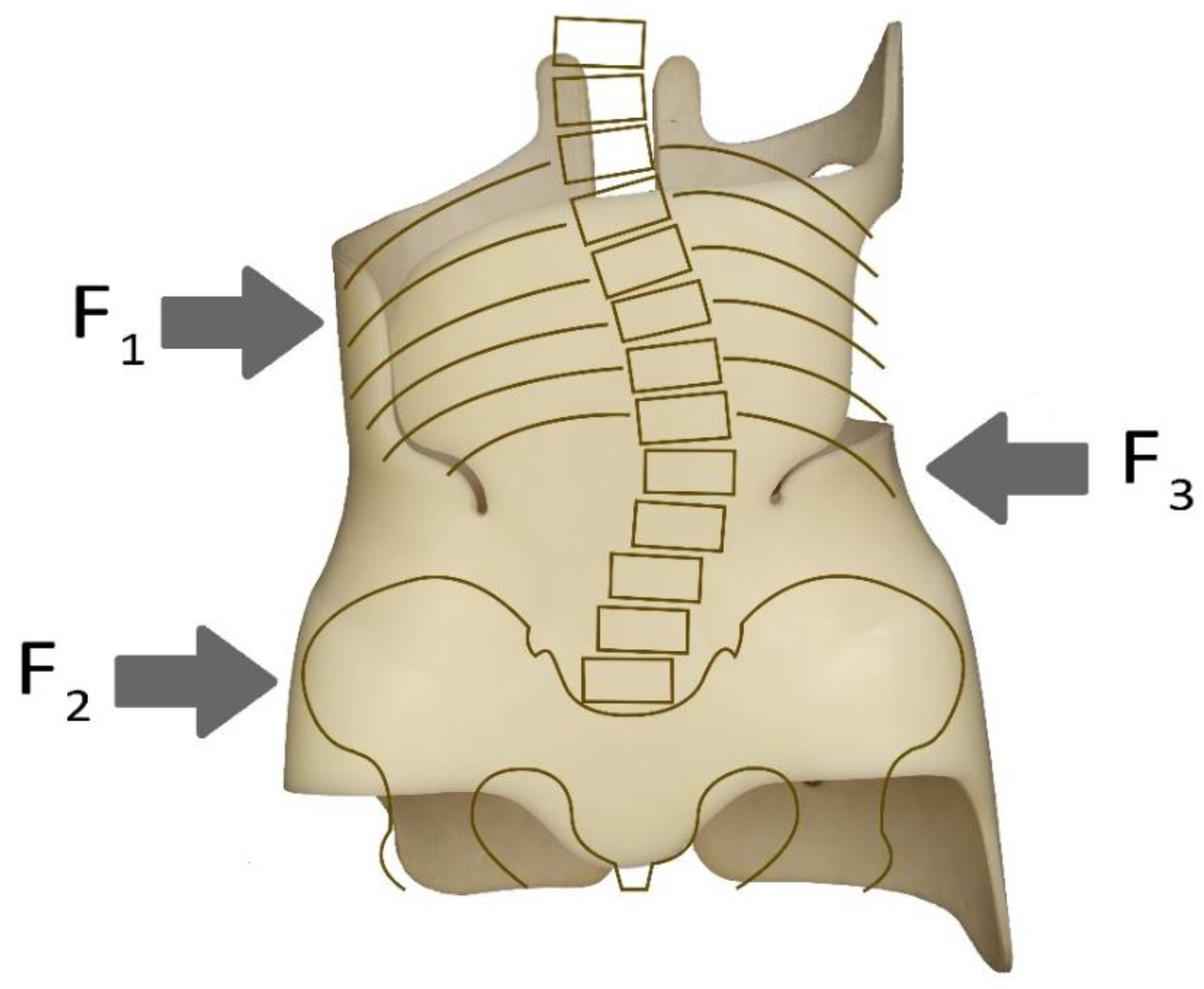
3]. The simplest corrective action of the orthoses involves the application of forces at the top of the curvature of the spine and at the support points at two places on the other end. This is the so-called three-point pressure system [
4]. Advanced designs, for example, the Cheneau orthosis, are based on the use of a multiple three-point correction scheme in 3D space [
5]. Improper methods of applying forces would result in ineffective therapy or, in the worst case, an increase in spinal curvature.
Currently, computerised methods are increasingly being used to design braces. Two main approaches can be distinguished. The first, which can be seen, for example, in the design of the CtrlBrace, uses computer-aided design (CAD) and computer-aided manufacturing (CAM) and involves taking measurements of the patient’s torso without posture correction, followed by modelling of the corrective brace’s geometry by means of a CAD/CAM operation, carried out by an experienced, professional orthotics designer [
2,
6,
7,
8]. The second approach, for example in the case of NewBrace [
9], focuses on the use of torso geometry described by the finite element method (FEM) for design purposes. To this end, the results of computed tomography (CT) or magnetic resonance (MR) medical imaging, and sometimes a 3D scan of the torso, are used, from which a body model is obtained, representing the actual structure of the musculoskeletal system [
6,
9,
10,
11]. The geometric image of the torso’s FEM model, after correction by the computer-modelled spatial field of pressures, is used as the model of the brace’s geometry. Due to the difficult issue of contact and the presence of complex anatomical structures in the human torso, in practice, it is not possible to faithfully represent FEM-determined fields of corrective pressures on the torso. In articles by Cobetto et al. [
9] and Weiss and Kleban [
12], the authors compare the effectiveness of braces designed using CAD/CAM computer methods combined with FEM. They emphasise that each of these methods has its pros and cons, and that combining them may bring about better efficacy of bracing. The efficacy of action of the designed braces can be practically verified, for example, through X-ray or CT imaging of the patient wearing the brace.
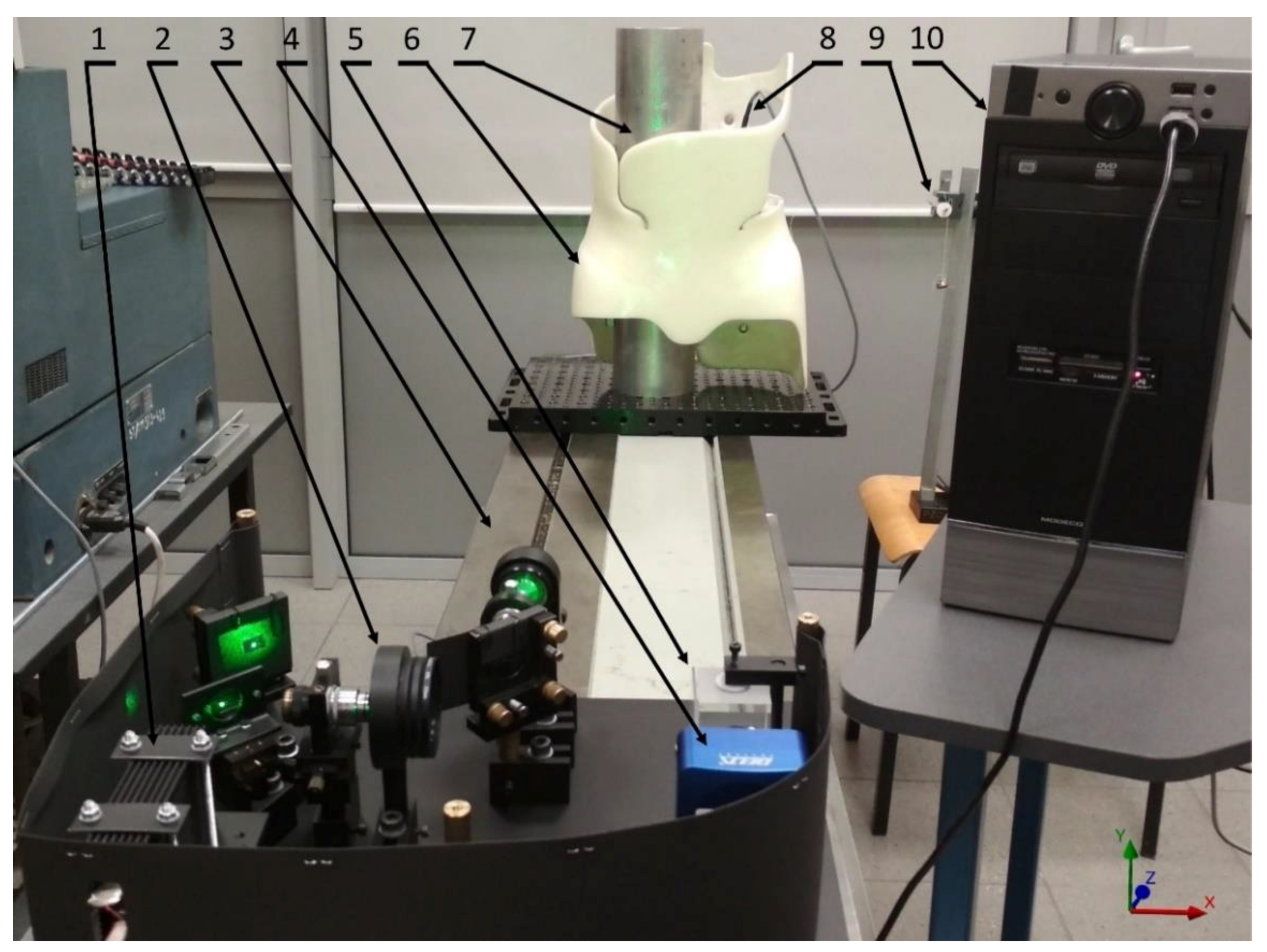
In research, experiments to determine the forces generated in orthosis components, such as the straps that tighten the orthosis, during corrective work, or the forces acting on the orthosis, are important in brace design research. For example, arrays with a large number of pressure sensors placed inside the orthosis are used [
13,
14,
15]. Two research directions may be identified. In the first variant, testing is carried out involving the patients [
13]. In the other variant, a standard force test stand with three-point loading of the orthoses is used [
16].
It can be seen that the current progress in rigid orthoses is focused on a better comprehension of their correction functionalities [
4], which are defined, inter alia, by the spatial force field required to act on the trunk, as well as, although less so, by the mechanical characteristics of the orthoses that are required to perform those functionalities. Examples of FEM applied to describe individual braces as an additional option accompanying FEM modelling of the torso can be found in the literature [
17], but these brace designs are simplistic and fail to adequately replicate real brace geometry. Liao et al. [
13] presented a more accurate model, but the results of FEM analysis pertained solely to the narrow problem of topological optimisation of the design, without a detailed analysis of the distribution of stresses and deformations in the orthoses structure.
Due to the nature of the structure, 3D modelling of the orthosis structure appears to be a challenging exercise. They are thin-walled, have cross-sectional openness and are subject to spatial force distribution. The relationship between the mechanical properties of the orthosis material and the pressures applied by the brace is debated in the literature [
1]. Rigid orthoses are better at exerting corrective forces, while flexible ones tend to be more comfortable to use. There is an extensive literature on the subject of determining the distributions of corrective forces [
3,
7,
8], but there is little information on the subject of the orthosis design’s mechanical properties, which are indispensable for effecting these forces [
11,
14]. Analysis of the literature indicates that the proper directions and amounts of the correction forces in an orthosis are a determining factor in its effectiveness. Therefore, the mechanical requirements that the orthosis must meet to ensure its ability to realise the required pressure fields appear to be equally important. It seems that an analysis of principal stress vectors and determination of force flow lines based on them can provide more information about the orthosis. This is one of the many directions used in issues concerning the optimisation of mechanical structures, but the literature lacks detailed information on the work of the brace itself.
The influence of the brace structure on its functional properties, such as: weight, the level of the patient’s thermal comfort, the level of gas exchange between the torso and the environment, and compliance to therapy, is not only an application issue, but also has a significant scientific importance. The problem of reducing the amount of brace material while increasing its functional properties and maintaining the unchanged corrective function is a big challenge. It seems that this task can only be solved with the use of advanced methods of analysis of the mechanical structure of the orthosis. The results of this analysis and the applied design improvements can obviously affect all medical aspects of the use of the orthosis and, most importantly, the assessment of the orthosis from the patient’s point of view. It seems that the presented methods of designing braces have a varying impact on increasing their functional parameters, important from the patient’s perspective. This article proposes a brace design analysis, which includes the possibility of preserving the material in places where it is necessary to ensure the unchanged corrective function of the orthosis. It seems that this type of analysis procedure should lead to the proposal of the lightest and the most functional brace structure for the patient. One may pose the hypothesis that the development of a reliable numerical model of a real orthosis, whose effectiveness has been proven in practice, is the best starting place to analyse the mechanical properties of orthosis designs. The results of in-depth modelling of such designs are rarely found in the literature. The goal of the numerical simulations and experimental tests presented in this article is to develop a reliable, experimentally verified FEM model of an exemplary orthosis. An in-depth model analysis will be used as the foundation for defining the performance scheme of the orthosis design, allowing potential opportunities for design optimisation to be identified.
4. Discussion
A series of tests were carried out to differentiate the values of the applied external load in the three-point system of forces, without changing their points of application. The results of measurements of the displacement distribution were of a similar nature; therefore, the article presents a representative example of a three-point load case. This case of force distribution corresponds to a given variant of scoliosis. In the event of using a brace by the patient, the values of the forces exerted by the orthosis on the torso undergo certain changes, but the general nature of their distribution does not change because the patient’s variant of scoliosis does not change. As a result, the nature of the distribution of strains and stresses in the brace does not change significantly. In the case of the three-point pressure principle, the results of the application of forces are unambiguous and immediate, which is confirmed by studies using ESPI and FEM.
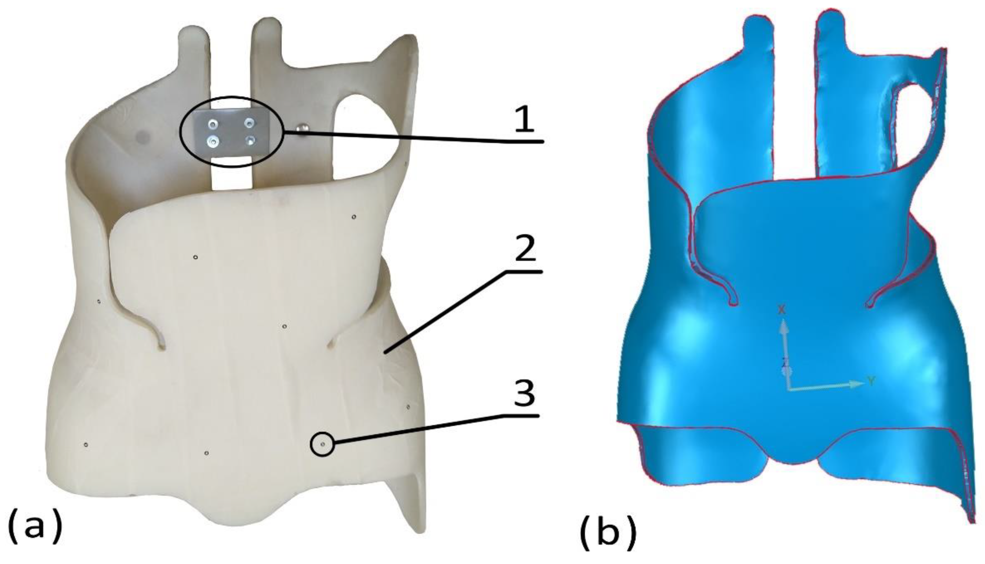
The results of the model verification tests, presented in
Figure 6, indicate the clear similarity between the distribution of displacement contour lines in the FEM image and the pattern of ESPI correlation fringes. A quantitative comparison of the obtained results of the numerical simulations with the experimental results shows that the relative difference in displacements in the central part of the brace’s front wall, determined according to both methods, is small and amounts to approximately 0.6%. Despite the fact that only out-of-plane displacements of the brace were measured, their good compliance with the results of FEM calculations on the entire front surface, covering almost half of the brace, allows the conclusion that this method of model verification is sufficient. By using the linear-elastic relations, it allows one to conclude on the values of strains and stresses related to the displacement field. In uniaxial tension (compression), Hooke’s law has the form (Equation (2))
where:
σ—normal stress,
ε—strain,
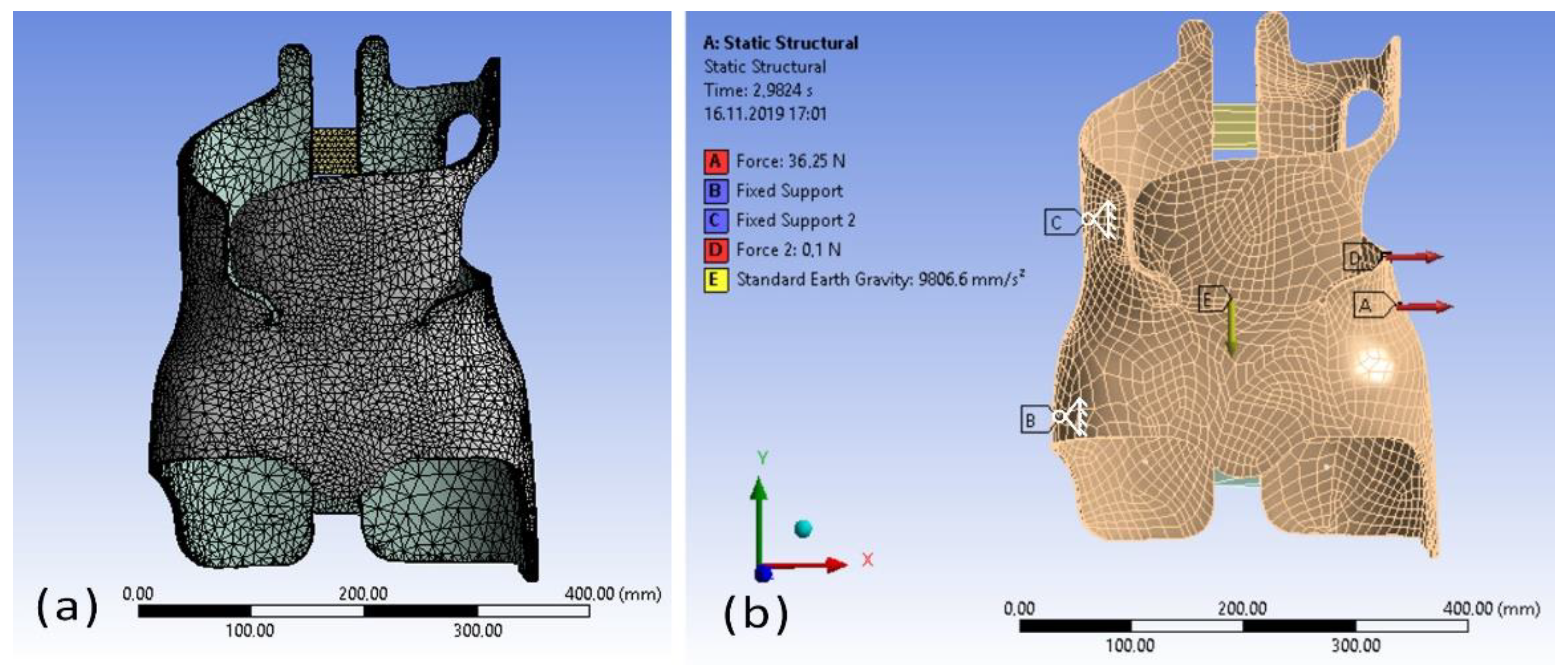
E—Young’s modulus. It can therefore be accepted that the proposed method of describing the orthosis geometry, the applied values of the mechanical parameters of the materials used for modelling and, above all, the density of the mesh and type of finite elements used for FEM description, allow the development of a model with high correspondence between its mechanical characteristics and the characteristics of the actual object. As a result, it appears that using the FEM model for additional testing, using different variants and values of loading in distributions similar to those seen in real life, could provide a foundation to draw conclusions about the work of a real life brace.
Taking an approach in the direction defined in this way, a conventional analysis method of the FEM modelling results output was used, consisting of the calculation of the von Mises stress distribution at loads equal in order to the magnitude of the common correction loads, imposed in accordance with an elementary “three-point system”.
Figure 7 shows that the chosen thickness of the polypropylene shell provides the orthosis with the required strength parameters. Von Mises Equivalent stress is determined on the basis of strength hypotheses. Equivalent stress represents the action of all the component stresses in a loaded body and its value must be less than or equal to the critical stress depending on material yield strength and the assumed factor of safety. The von Mises stress values for this material are significantly below the allowable stress (
Fα) values. Apart from the force application and support locations, the stress values in other parts of the orthosis were less than 4.4 MPa, consistent with the linear stress–strain curve characteristics of polypropylene [
25]. It is possible to identify the areas of the orthosis that are most vulnerable to mechanical damage and those that do almost no work. Even if a similar “three-point system” was used, it might be hard to generalise the obtained results to orthosis cases with different applied load values and geometric parameters due to the quite irregular stress distribution in the orthosis body (
Figure 7). As can be seen from von Mises stress calculations, the most stressed areas are the force application areas. In the study, very small force application areas were assumed in order to reduce the discrepancy between the experimental boundary conditions and the numerical model. In reality, the force application areas are larger and thus the stresses are much lower near force application areas. Nevertheless, the distribution of von Mises stresses, as shown in
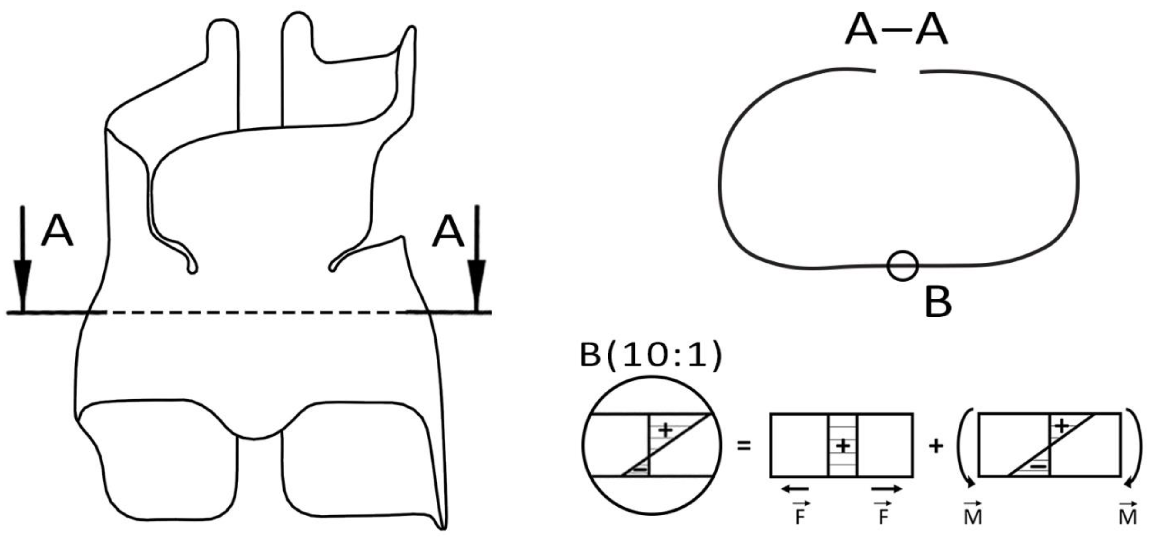
Figure 6 in areas other than the applied forces, obtain values significantly lower than the allowable stresses, indicating that the shell can be optimized. The principal stress distributions, which are shown in
Figure 8 for different sections of the structure, seem to give more information in the general context of the performance of the orthoses. The outer surface of the front wall of the orthosis is in compression, while the inner face of the same wall is in tension. The values of absolute stresses on the interior side are approximately two times higher than those on the exterior layer. The rest of the shell of the brace works in a similar way. The characteristic stress distribution, characterised by a significant value of tensile stresses on the inside of the orthosis shell, is due to the superposition of stresses from two independently operating types of loads. The bracing shell is subjected to combined tension and bending states, as can be seen by comparing the signs and values of the stresses acting (
Figure 10). This observation is crucial to the proposal of the bracing optimisation method described later in this article, as it makes it possible to determine which site of the bracing wall is going to be subjected to the greatest tensile stress.
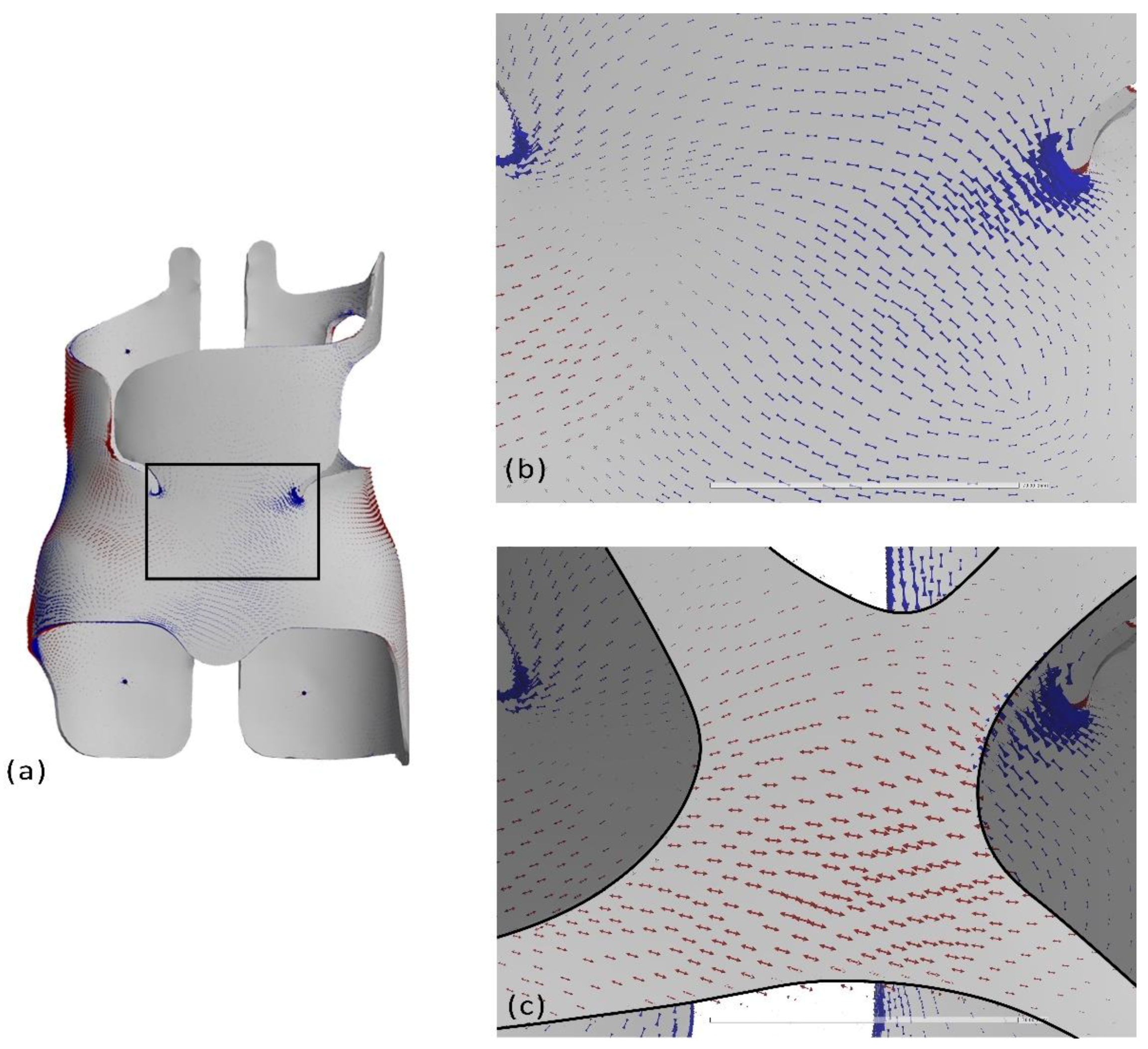
Clear regularities shaping the obtained image of the lines can be seen from the determined vector fields of principal stresses and drawn maximum principal stresses
σ1 trajectories in the regions in which these stresses take relatively large values (
Figure 9). The trajectories of the principal stresses follow a characteristic pattern, connecting the correction load locations along paths of a relatively small sum of lengths. This image depicts the “force flow lines” concept that is currently being intensively developed in the theory of optimal design [
26]. It is based on the insight that, in principle, the “flow” of forces across a mechanical structure among external load application points is strongest near the topographic lines connecting these locations in space, taking into account the imposed limits of the geometry of the structure. Although trajectories of principal stress are one way to practically apply the idea of “force flow lines”, the literature offers alternative rival proposals [
27]. On the basis of this idea, the orthosis may be characterised as a space-based mechanical system that transmits loads along comparatively brief trajectories between locations where correction loads are applied. It seems that analysis of principal stress vectors can provide more information about the orthosis. Principal stresses describe the stress state represented by normal stresses only, with zero tangential stresses. They are a useful way of presenting force flow lines. The force flow line is a concept used to visualize the path of an applied load through a load bearing member. This is one of many methods used in issues of the optimisation of mechanical structures, which are intensively developed, but the literature lacks detailed information on the work of the brace itself. The analysis in the proposed paper deals with one particular force application scheme. The lines of force flow will change due to the type of loading scheme, but will be almost identical when changing only the values of forces. In this way, based on the space trajectories distribution presented in
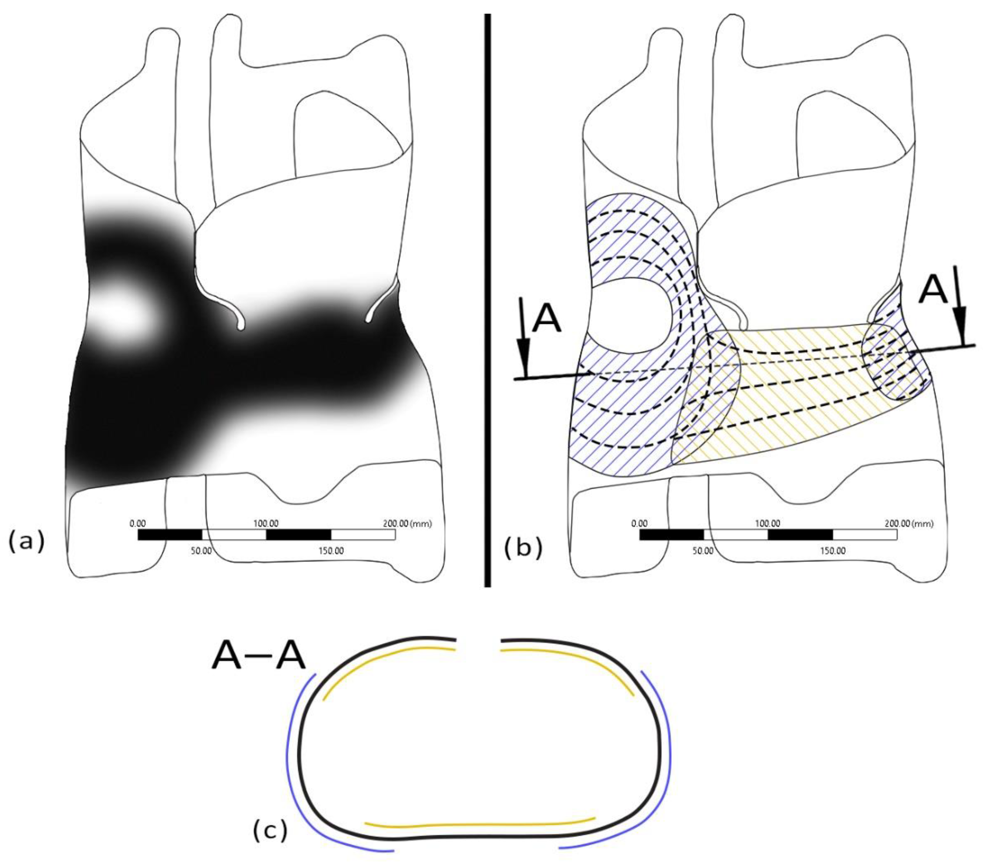
Figure 9, it is possible to determine the orthotic area responsible for performing the orthosis’ correction function. Other regions perform a supportive role, for example, stabilising the orthosis against the body. In
Figure 11a, areas of the orthosis structure that require less effort and have a supporting role are shown in the dark colour, while areas of the brace structure that require less effort and have a supporting role are shown in the light colour. The location of the correction region will be similar to that specified in the optimisation routine [
13]. Nevertheless, in comparison with the approach of minimising the elastic energy in the method of topological optimisation, it appears the method presented above for analysing the performance of a structure is more comprehensible in the context of stress distribution analysis. There are no studies in the literature to date that have analysed principal stress for orthoses. On the basis of the numerical model analysis results shown previously, it is possible to propose methods for practical use. Based on the research findings, the weight of the orthosis can be reduced with no significant change in the mechanical performance of the orthosis, especially the orthosis stiffness in regions bearing correction loading. A simple solution may be to make the orthosis from thinner material by using an additional stiffener at the dark-coloured region in
Figure 11a, which carries the corrective loads. The orthosis can be more rigid in this region by incorporating thin layers of composite with carbon or glass fibre reinforcement, orientated alongside the principal stress trajectory illustrated in
Figure 11b. A comparison of
Figure 7,
Figure 8 and
Figure 9 clearly shows that the most effective overlap would be on the inner face at the front of the orthosis, as the inner face is subjected to a much higher loading in this region than the outer face. In the vicinity of the correction force points, the situation is reversed: the outer face bears considerably more load than the inner face, so overlays should be applied on the exterior, as shown in
Figure 11c. In a similar way, locations for the overlays to be applied to other regions bearing correctional loads can be determined.
It can be seen from the above discussion that, for a three-point force system, it is fairly easy to predict the trajectory of the force flow line in the orthosis, which serves as the foundation for determining the regions that need strengthening. At its most basic, the orthosis corrects the curvature using the principle of three-point compression, which consists of fixing below, above and on top of the curvature [
28]. Selected experimental configurations mimic the physiological load as closely as possible. In difficult cases, the experimental stand and the numerical modelling need to consider the corresponding more complicated arrangements. However, it appears that the procedure described can be used to optimise orthosis design in these more complex cases as well. However, further numerical calculations are needed to verify that hypothesis. The other way to use the findings of the study in practise would be to remove material, for example, through drilling holes in regions that are irrelevant to the correction performance of the orthosis (the light-coloured area in
Figure 11a).
The present trend in orthoses testing is to find a material that can be used as a replacement for polypropylene and can be printed using the FDM method [
29]. The obtained results are an excellent contribution to this trend because they can form the basis for the development of a method for the realisation of a printed 3D design model supported on an openwork geometry that corresponds to the distribution of the trajectory of principal stresses, at the same time meeting the condition of minimum mass and maintaining the desired rigidity characteristics of the design [
13].
The findings of this study may serve as a foundation for future work aimed at optimising the orthoses shape through stiffening and mass reduction. Using the conclusions reached from the modelling, particularly the distribution of principal stress directions and values, it is possible to propose an alignment of stiffening components that work in accordance with the determined principal stress directions. Simultaneously, it is able to lower the mass of the orthoses by decreasing the amount of material in areas of the braces that are not exposed to as much load.


