Article

Dose-Area Product Determination and Beam Monitor Calibration for the Fixed Beam of the Shanghai Advanced Proton Therapy Facility

1
Institute of Nuclear and New Energy Technology, Tsinghua University, Beijing 100084, China
2
Shanghai Institute of Applied Physics, Chinese Academy of Sciences, Shanghai 201800, China
*
Author to whom correspondence should be addressed.
Appl. Sci. 2022, 12(9), 4111; https://doi.org/10.3390/app12094111
Submission received: 12 March 2022 / Revised: 14 April 2022 / Accepted: 14 April 2022 / Published: 19 April 2022
(This article belongs to the Special Issue Detectors for Medical Physics)

Abstract

:
Research conducted to-date, makes use of the IBA-Lynx scintillating screen and radiochromic film to analyze the proton field uniformity for dose-area product (DAP) determination. In this paper, the machine log file based reconstruction is proposed to calculate the field uniformity to simplify the measurement. In order to calculate the field uniformity, the dose distribution is reconstructed based on the machine log file with matRad (an open source software for analytical dose calculation in MATLAB). After acquisition of the dose distribution, the field flatness and symmetry are calculated automatically for different proton energies. A comprehensive comparison of DAP determined with Bragg peak chamber (BPC) and Markus chamber (MC) is presented. The actual delivered dose is reconstructed with the log file to analyze the lateral dose distribution of the scanned field. DAP of different energies are calculated ranging from 70.6 MeV to 235 MeV. The percentage difference is calculated, illustrating the DAP discrepancy between the MC and BPC to the mean value. The percentage difference ranges from −0.19% to 1.26%. The variation between DAP measured with the BPC and MC peaks at −2.5%. The log file based reconstruction to calculate field uniformity can be an alternative for DAP determination. The direct method using a large-area Bragg peak chamber is investigated. The two methods to determine DAP and calibrate beam monitor illustrate consistent results.

1. Introduction

Beam monitor calibration is significant for dose delivery accuracy in the dosimetric commissioning of a proton beam therapy facility. Conventionally, beam monitor calibration is performed in terms of dose per monitor unit (MU). The beam monitor in scanned ion-beam delivery can be calibrated in terms of the number of protons or DAP to water at the shallow depth in the scanned field with uniform lateral dose profile. DAP was proposed as reference dosimetry for proton pencil beam [1] because there is no detailed procedure outlined in IAEA TRS-398 [2] for scanning beam dosimetry. One method to derive DAP is to measure the point dose in the center of a large uniform field [3]. It is employed in most facilities now. Another method is to determine the DAP of a single beamlet employing a large-area parallel ionization chamber, such as Bragg peak chamber [4,5]. The direct method has recently received considerable interest as an alternative but has so far been little explored.
Accredited primary standard laboratories in China do not provide the calibration factor in terms of absorbed dose to water for BPC. One can obtain this calibration factor by cross-calibration with Farmer chamber or Markus chamber in a large scanned field with uniform lateral dose profile. Lateral response heterogeneity of the BPC should be taken into account; if not, approximately 3% error of DAP will be triggered [4,6]. Gillin et al. [7] cross-calibrated the BPC with a Farmer type chamber in the center of a Spread-out Bragg Peak (SOBP). DAP was determined at the plateau region of mono-energetic proton pencil beam with both methods [4,8].
The delivered particles per MU can be calculated combining ionization chamber measurements and the Monte Carlo simulation. A 10 × 10 cm2 uniform field with the spot spacing 2.5 mm and given number of protons were simulated in TOPAS, sharing the same properties as the experiment [9]. Jäkel [3] performed the calibration of the beam monitor at a shallow depth with a uniform field for carbon beam. The number of protons per MU was calculated with a uniform field for proton beam [9,10,11,12]. Beam monitor calibration in terms of the number of protons with a single spot and uniform scanned field was analyzed [8,13,14]. The beam monitor was calibrated with an ionization chamber and a Faraday cup [9,15].
If the lateral dose distribution is not uniform, an additional corrective factor should be added to DAP determination. In addition, the scanned field uniformity can contribute to the uncertainty of DAP determination. A 0.5% uncertainty budget is found by Osorio [8] corresponding to the uniformity of the beam profile. Thus, it is necessary to analyze the scanned field uniformity. In previous research, lateral dose distribution was measured with the IBA-Lynx scintillating screen or radiochromic film to check the field uniformity [4,8]. In this paper, it is proposed to utilize the log file based reconstruction to calculate the lateral dose uniformity for DAP determination. Furthermore, Beam monitor calibration is significant in the dosimetric commissioning of the proton beam therapy facility. The beam monitor performance is tested in periodic quality assurance (QA) because it is directly related to the dose delivery accuracy. During the commissioning stage of China’s first domestically-made proton therapy facility named the Shanghai Advanced Proton Therapy facility (SAPT), the BPC and MC are employed to derive DAP and calibrate the beam monitor in terms of the number of protons per MU.

2. Materials and Methods

2.1. SAPT and Beam Monitor System

SAPT is a synchrotron-based facility with a fixed beam treatment room, a 180° gantry treatment room, a 360° gantry treatment room and an ocular treatment room. It can provide 94 nominal energies from 70.6 MeV to 235 MeV. Spot size (FWHM) at ISO-center in air varies from 6 mm to 13 mm. In SAPT, 1 MU denotes that every 20 nC charge was collected by the beam monitor. 1 MU is defined as 100,000 counts. Virtual source to axis distance (VSAD) from scanning magnet U and V to ISO-center are 2.87 m and 2.49 m respectively [16]. Beam monitor is comprised of a primary dose monitor, a secondary dose monitor and a position monitor. Dose monitors are parallel plate ionization chambers; the position monitor is a multi-strip ionization chamber.

2.2. DAP Measurement with Single-Layer Method

A plane-parallel ionization chamber (Markus chamber type SN001790 TM23343, PTW-Freiburg) was positioned at depth 2 cm in the water tank. The Markus chamber was connected to a Unidos webline (Series No. T10022-002056, PTW-Freiburg). The front window of the water tank was aligned to the ISO-center. A 10 × 10 cm2 square field with uniform lateral dose profile was scanned with 32 energies ranging from 70.6 MeV to 235 MeV. The spot spacing was 2.5 mm at ISO-center. The Markus chamber was positioned in the center of the square field (Figure 1). Therefore, spot spacing at water depth 2 cm can be computed employing a similar triangle equation. Pressure and temperature correction factor, electrometer calibration factor, polarity correction factor and the recombination correction factor were measured according to the procedure of IAEA TRS-398 [2]. All the measurements were conducted with the fixed beam.
DAP measured with MC in a uniform field, D A P w A ( M a r k u s ) is calculated by:
D A P w A ( M a r k u s ) = M M a r k u s × N D , w , M a r k u s × k Q , Q 0 × Δ x × Δ y × F S C F
where M M a r k u s is the readout of the ionization chamber. N D , w , M a r k u s is the calibration coefficient in terms of absorbed dose to water. k Q , Q 0 denotes the beam quality correction factor. Δ x and Δ y are the spot spacing at water depth 2 cm. FSCF is the field size correction factor (FSCF).

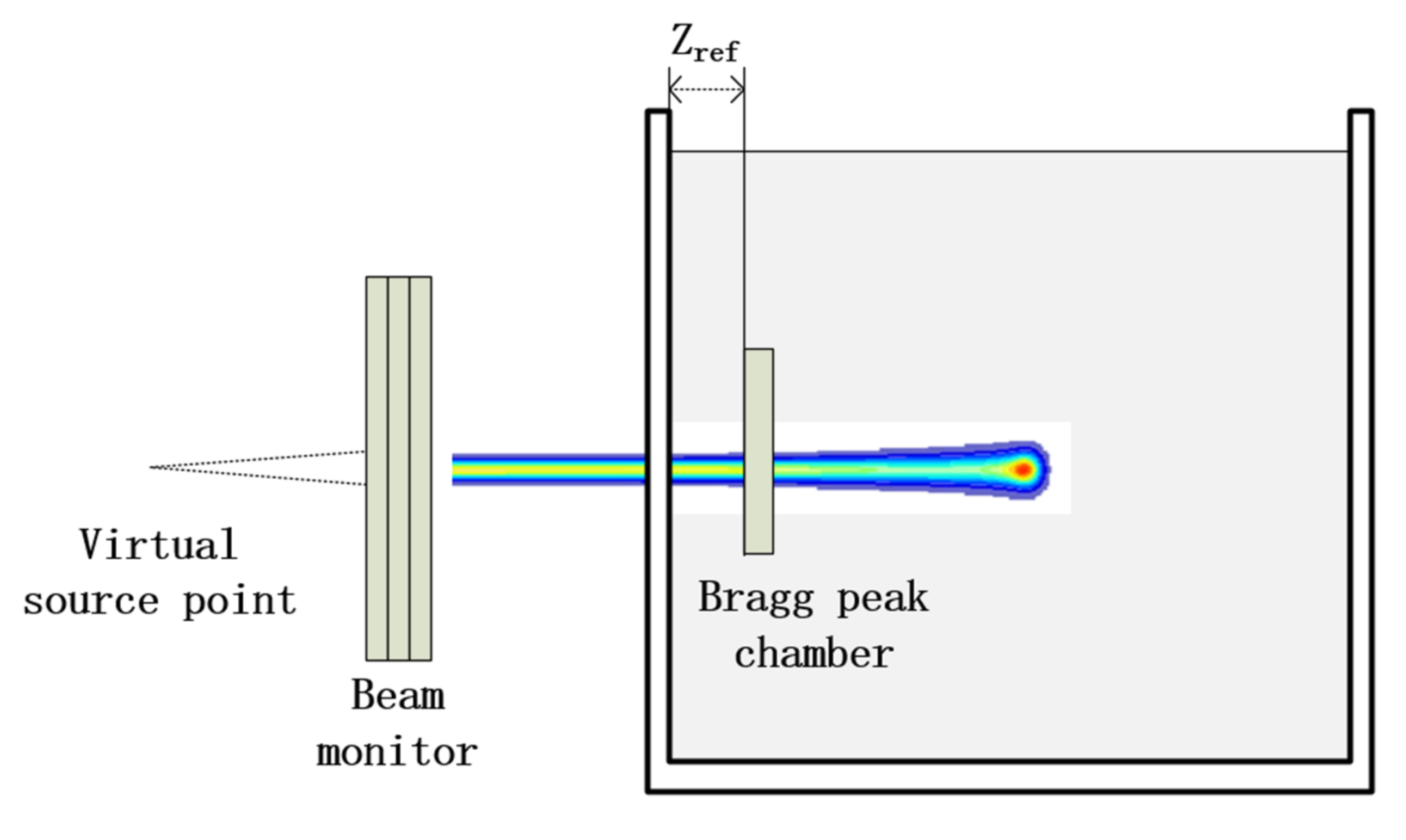
2.3. DAP Measurement with Single-Spot Method

The single-spot method is a direct determination of DAP. A large-area ionization chamber (Bragg peak chamber type TM34070, PTW-Freiburg) was positioned at depth 2 cm in the water tank. The BPC is cross-calibrated against an MC. The experiment setup is shown in Figure 2.
DAP measured with BPC in a beamlet, D A P w A ( B P C ) is obtained as:
D A P w A ( B P C ) = M B P C × N D , w , B P C × A B P C × C S C F
where M B P C is the charge measured with the BPC. N D , w , B P C is the cross-calibrated coefficient in a proton beamlet for BPC. A B P C is the area of the BPC. CSCF is the chamber size correction factor (CSCF).
The calibration coefficient for the BPC is cross-calibrated with the MC in a large scanned field. The calibration coefficient is given by:
N D , w , B P C = M M a r k u s × N D , w , M a r k u s × k Q , Q 0 M B P C F I E L D × C R H B P C × A O A R ( x , y ) d x d y
where M B P C F I E L D is the charge measured with BPC in the 10 × 10 cm2 large field. C R H B P C is the chamber response heterogeneity (CRH) which is attributable to the non-uniform lateral response of BPC [4,6]. OAR(x,y) is the off-axis ratio at lateral position x and y [6]. If the lateral dose distribution is not uniform, the additional factor (integration of the off-axis ratio) is added. In order to check the dose uniformity over the chamber area, a log file-based dose reconstruction was employed. The details for the reconstruction are described in Section 2.5. The 10 × 10 cm2 field may not be large enough for the BPC. A correction factor is added with the Monte Carlo simulation. Two square fields were simulated, 10 × 10 cm2 and 20 × 20 cm2 and dose was scored for the sensitive volume of BPC. The correction factor is the ratio of the scored dose with the two large fields.

2.4. Nozzle Monte Carlo Modelling of SAPT

FSCF, CSCF and CRH were derived from the Monte Carlo simulation. Firstly, the SAPT nozzle was modeled in TOPAS (version 3.1) [17]. The FSCF was obtained by simulating a 10 cm × 10 cm field and 20 cm × 20 cm scanning field with spot space 2.5 mm. The Sensitive volume of the Markus chamber is modeled to obtain the central dose of the two large fields. FSCF denotes the ratio between the dose of the two fields. CSCF is acquired by scoring the dose in a cylindrical region with radius 4.08 cm and 10 cm. It denotes the ratio between the simulation results of two different scoring radii. In order to obtain CRH, the actual response curve of the BPC is simulated. The spot is scanned along the radius of the BPC from the chamber center to the boundary. Detailed calculation can be found in [4]. The simulated particles for each spot were 106. The virtual source to axis distance (VSAD) from the scanning magnet U and V to the ISO-center is 2.87 m and 2.49 m respectively [16]. Beam monitors are composed of the main and secondary dose monitors and a position monitor. The water equivalent thickness (WET) of the three dose monitors is 1.9 mm. Protons pass through the vacuum chamber in the nozzle. A simplified SAPT nozzle model used for the TOPAS simulation is shown in Figure 3. The Markus chamber was positioned in a 40 × 40 × 40 cm3 water phantom at depth 2 cm.
A single spot was simulated and the dose was scored in a cylindrical volume with a radius of 4.08 cm. The actual delivered particles are given by:
N d e l i v e r e d p = D A P i ( S e l , i / ρ ) w Φ E , i A ( z r e f ) d E N M C p A
where DAP is the calculated dose-area product derived from the Markus chamber measurement. S e l , i / ρ is the mass stopping power for species i. TOPAS uses revised ICRU 73 [18] stopping power tables. Φ E , i A ( z r e f ) is the fluence differential within the area A. A denotes the area of the cylindrical volume. The denominator can be derived by the Monte Carlo simulation [14,19].

2.5. Log File Based Dose Reconstruction to Inspect the Iniformity

If the lateral dose profile is not uniform, an additional correction factor should be added to the DAP equation [13]. In order to check the field uniformity, a single-energy dose distribution was reconstructed based on the log file. The actual delivered spot positions, size and weight were recorded in the log file by the beam monitor. These parameters were employed to reconstruct the dose distribution to inspect the field uniformity with matRad (an open source toolkit for radiation therapy planning) [20]. Source-to-axis distance (SAD), integral depth dose (IDD) curve and spot size in air at different positions of 94 energies of SAPT were input into the machine data of matRad. The field uniformity (defined as flatness and symmetry) was calculated using the equation in TG-224 [21]. Tolerance of the field flatness and field symmetry are ±2% and ±1% respectively.

3. Results

3.1. Single-Energy Dose Distribution

The reconstructed dose distribution at depth 2 cm of incoming energy 83.8 MeV is shown in Figure 4a. The lateral dose profile is demonstrated in Figure 4b. Uniformity of all the energies is within the tolerance. Thus, the correction factor of field uniformity is superfluous.

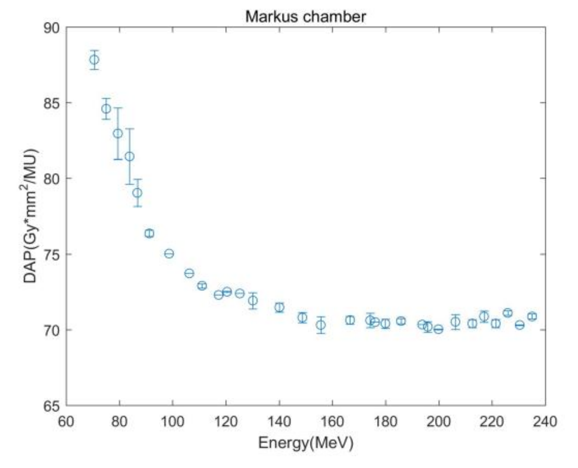
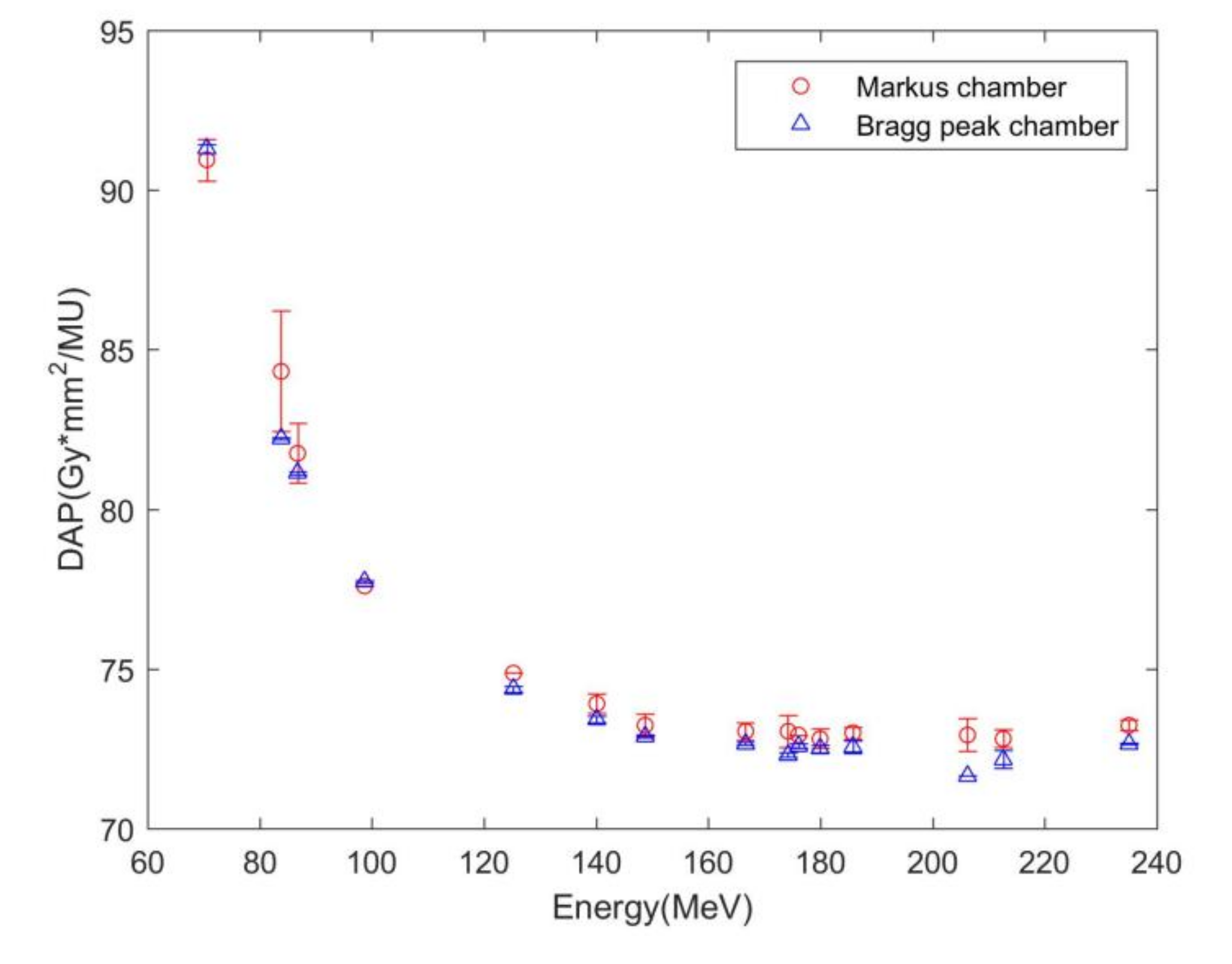
3.2. DAP Measurement

DAP measured with MC of 32 energies is shown in Figure 5. Obvious large error bars can be seen in the low energy region, ranging from 70.6 MeV to 86.8 MeV compared to that in the high energy region. This deviation illustrates the discrepancy between different measurement times. DAP at energy 83.8 MeV measured with MC illustrates the largest error bar, 1.89 Gy*mm2/MU. This shows the instability of the scanning field at low energy 83.8 MeV.
Comparison of DAP measured with MC and BPC is shown in Figure 6. The error bar demonstrates the standard deviation from the repeating measurements. Mean DAP is the average of DAP measured with MC and BPC (Table 1). The percentage difference illustrates the discrepancy of DAP measured with BPC to that with MC, ranging from −0.19% to 1.26%. The single-layer method can be used as reference dosimetry. The percentage difference between DAP measured with the BPC and MC ranges from −2.5% to 0.39%. The largest deviation occurred at energy 83.8 MeV due to the instability of scanning field at low energy during the commissioning stage of SAPT.

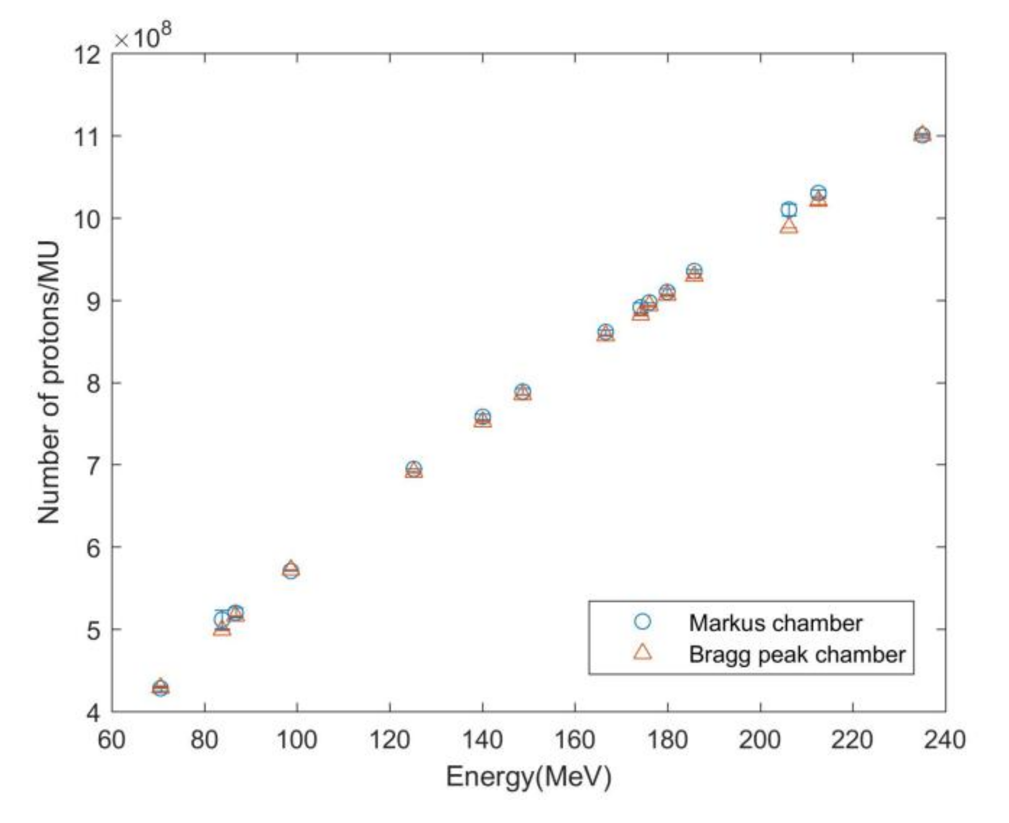
3.3. Number of Protons per MU

The beam monitor calibration in terms of the number of protons per MU is derived from the DAP measurement and the Monte Carlo simulation. The beam monitor in the nozzle of different energies was calibrated with both measurement results and the Monte Carlo simulation (Figure 7). Both methods demonstrated consistent results. The error bars derived from MC were bigger than those derived from the BPC at low energy regions. The peak value takes place at 83.8 MeV. The error comes from the uncertainty of DAP measurement and is attributed to the instability of the scanned field. The percentage difference in Table 2 denotes the difference in the number of protons per MU derived from the BPC compared to that from MC. The maximum deviation was 2.61%.

4. Discussion

DAP determination with the single-layer and single-spot method was comprehensively compared. The standard deviation of the BPC measurement is smaller than that of the MC measurement. The error bar of DAP measured with MC is most significant at energy 83.8 MeV. This may well be attributable to the repetition and instability of the scanning field at low energies. DAP of 32 energies with single-layer method was obtained while 15 energies with single-spot method was determined. The field uniformity was inspected by reconstructing the dose distribution with the log file rather than measurement. The simulation of the single beamlet was validated with the scintillating screen measurement. The chamber response heterogeneity is simulated by Monte Carlo simulation. It is chamber dependent and should be calculated based on Bragg peak chamber measurement. Approximate 3% error will be induced, if one neglects this correction factor. In order to acquire a uniform field, the field was repainted five times.
Type A uncertainty is obtained by calculating the standard deviation from different measurements as shown in Table 1 and Table 2. The most significant standard deviation of DAP measured with MC happens at the low energy region, peaking at 83.8 MeV. The error bars of DAP measured with the BPC demonstrate smaller values by contrast to that with MC. Type B uncertainty was derived based on our best knowledge and experience. There are 0.3%, 0.1%, 0.5% and 0.5% uncertainties for the CSCF, FSCF, CRH and water tank positioning accuracy respectively [3]. However, a comprehensive uncertainty analysis is needed for both methods. This paper presents a preliminary uncertainty comparison of single-energy and single-spot method for SAPT.

5. Conclusions

Markus chamber and Bragg peak chamber were employed to determine DAP and calibrate beam monitor in terms of number of protons per MU. Both methods illustrate consistent results. A preliminary uncertainty analysis is presented for DAP measurement. Correction factors should be carefully calculated when using the direct determination of DAP. Single-spot method with the Bragg peak chamber can be employed as an alternative for DAP determination.

Author Contributions

Conceptualization, L.Z. and X.W.; methodology, L.Z. and X.W.; software, L.Z.; validation, X.X. and X.W.; formal analysis, L.Z.; investigation, L.Z.; resources, M.Z.; data curation, M.Z.; writing—original draft preparation, L.Z.; writing—review and editing, L.Z. and X.W.; visualization, L.Z.; supervision, X.X.; project administration, X.W.; funding acquisition, X.W. All authors have read and agreed to the published version of the manuscript.

Funding

This research was funded the National Key Research and Development Program (No.2016YFC0105406) and National Natural Science Foundation of China (No.61571262, No.11575095, No.61171115).

Institutional Review Board Statement

Not applicable.

Informed Consent Statement

Not applicable.

Data Availability Statement

Not applicable.

Acknowledgments

The authors appreciate Mei Chen of Shanghai Advanced Proton facility for the experiments and Stephen Conway for the grammar correction.

Conflicts of Interest

The authors declare no conflict of interest.

References

  1. Goma, C.; Safai, S.; Voros, S. Reference dosimetry of proton pencil beams based on dose-area product: A proof of concept. Phys. Med. Biol. 2017, 62, 4991–5005. [Google Scholar] [CrossRef] [PubMed]
  2. Andreo, P.; Burns, D.T.; Hohlfeld, K.; Huq, M.S. Absorbed Dose Determination in External Beam Radiotherapy. IAEA TRS 398 an International Code of Practice for Dosimetry Based on Standards of Absorbed Dose to Water; International Atomic Energy Agency: Vienna, Austria, 2000. [Google Scholar]
  3. Jäkel, O.; Hartmann, G.H.; Karger, C.P.; Heeg, P. A calibration procedure for beam monitors in a scanned beam of heavy charged particles. Med. Phys. 2004, 31, 1009–1013. [Google Scholar] [CrossRef] [PubMed]
  4. Shen, J.J.; Ding, X.N.; Hu, Y.L.; Kang, Y.X.; Liu, W.; Deng, W.; Bues, M. Technical Note: Comprehensive evaluation and implementation of two independent methods for beam monitor calibration for proton scanning beam. Med. Phys. 2019, 46, 5867–5875. [Google Scholar] [CrossRef] [PubMed]
  5. Farr, J.B.; Moyers, M.F.; Allgower, C.E.; Bues, M.; Hsi, W.-C.; Jin, H. Clinical commissioning of intensity-modulated proton therapy systems: Report of AAPM Task Group 185. Med. Phys. 2021, 48, e1–e30. [Google Scholar] [CrossRef] [PubMed]
  6. Kuess, P.; Bohlen, T.T.; Lechner, W.; Elia, A.; Georg, D.; Palmans, H. Lateral response heterogeneity of Bragg peak ionization chambers for narrow-beam photon and proton dosimetry. Phys. Med. Biol. 2017, 62, 9189–9206. [Google Scholar] [CrossRef] [PubMed]
  7. Gillin, M.T.; Sahoo, N.; Bues, M.; Ciangaru, G.; Sawakuchi, G.; Poenisch, F.; Arjomandy, B.; Martin, C.; Titt, U.; Suzuki, K.; et al. Commissioning of the discrete spot scanning proton beam delivery system at the University of Texas M.D. Anderson Cancer Centre, Proton Therapy Centre, Houston. Med. Phys. 2010, 37, 154–163. [Google Scholar] [CrossRef] [PubMed]
  8. Osorio, J.; Dreindl, R.; Grevillot, L.; Letellier, V.; Kuess, P.; Carlino, A.; Elia, A.; Stock, M.; Vatnitsky, S.; Palmans, H. Beam monitor calibration of a synchrotron-based scanned light-ion beam delivery system. Z. Med. Phys. 2021, 31, 154–165. [Google Scholar] [CrossRef] [PubMed]
  9. Rath, A.K.; Sahoo, N. (Eds.) Particle Raiotherapy. In Emerging Technology for Treatment of Cancer; Springer: New Delhi, India, 2016; pp. 1–194. [Google Scholar]
  10. Goma, C.; Lorentini, S.; Meer, D.; Safai, S. Proton beam monitor chamber calibration. Phys. Med. Biol. 2014, 59, 4961–4971. [Google Scholar] [CrossRef] [PubMed]
  11. Liu, C.; Ho, M.W.; Park, J.; Hsi, W.C.; Liang, X.; Li, Z.; Song, Y.; Feng, H.; Zhang, Y. Fast MCsquare-Based Independent Dose Verification Platform for Pencil Beam Scanning Proton Therapy. Technol. Cancer Res. Treat. 2021, 20, 1–10. [Google Scholar] [CrossRef] [PubMed]
  12. Huang, S.; Kang, M.; Souris, K.; Ainsley, C.; Solberg, T.D.; McDonough, J.E.; Simone, C.B., 2nd; Lin, L. Validation and clinical implementation of an accurate Monte Carlo code for pencil beam scanning proton therapy. J. Appl. Clin. Med. Phys. 2018, 19, 558–572. [Google Scholar] [CrossRef] [PubMed] [Green Version]
  13. Palmans, H.; Vatnitsky, S.M. Beam monitor calibration in scanned light-ion beams. Med. Phys. 2016, 43, 5835–5847. [Google Scholar] [CrossRef] [PubMed]
  14. Grevillot, L.; Osorio Moreno, J.; Letellier, V.; Dreindl, R.; Elia, A.; Fuchs, H.; Carlino, A.; Kragl, G.; Palmans, H.; Vatnitsky, S.; et al. Clinical implementation and commissioning of the MedAustron Particle Therapy Accelerator for non-isocentric scanned proton beam treatments. Med. Phys. 2020, 47, 380–392. [Google Scholar] [CrossRef] [PubMed]
  15. Lorin, S.; Grusell, E.; Tilly, N.; Medin, J.; Kimstrand, P.; Glimelius, B. Reference dosimetry in a scanned pulsed proton beam using ionisation chambers and a Faraday cup. Phys. Med. Biol. 2008, 53, 3519–3529. [Google Scholar] [CrossRef] [PubMed]
  16. Shu, H.; Yin, C.; Zhang, H.; Liu, M.; Zhang, M.; Zhao, L.; Chu, K.; Dai, X.; Moyers, M.F. Scanned Proton Beam Performance and Calibration of the Shanghai Advanced Proton Therapy Facility. MethodsX 2019, 6, 1933–1943. [Google Scholar] [CrossRef] [PubMed]
  17. Perl, J.; Shin, J.; Schumann, J.; Faddegon, B.; Paganetti, H. TOPAS: An innovative proton Monte Carlo platform for research and clinical applications. Med. Phys. 2012, 39, 6818–6837. [Google Scholar] [CrossRef] [PubMed]
  18. International Commission on Radiation Units and Measurements (ICRU). Stopping of Ions Heavier Than Helium, ICRU Report 73; Oxford University Press: Oxford, UK, 2005. [Google Scholar]
  19. Elia, A.; Resch, A.F.; Carlino, A.; Böhlen, T.T.; Fuchs, H.; Palmans, H.; Letellier, V.; Dreindl, R.; Osorio, J.; Stock, M.; et al. A GATE/Geant4 beam model for the MedAustron non-isocentric proton treatment plans quality assurance. Phys. Med. 2020, 71, 115–123. [Google Scholar] [CrossRef] [PubMed]
  20. Wieser, H.-P.; Cisternas, E.; Wahl, N.; Ulrich, S. Development of the open-source dose calculation and optimization toolkit matRad. Med. Phys. 2017, 44, 2556–2568. [Google Scholar] [CrossRef] [PubMed]
  21. Arjomandy, B.; Taylor, P.; Ainsley, C.; Safai, S.; Sahoo, N.; Pankuch, M.; Farr, J.B.; Park, S.Y.; Klein, E.; Flanz, J.; et al. AAPM task group 224: Comprehensive proton therapy machine quality assurance. Med. Phys. 2019, 46, e678–e705. [Google Scholar] [CrossRef] [PubMed] [Green Version]
Figure 1. Illustration of the setup for the DAP measurement in water with the single-layer method.
Applsci 12 04111 g001
Figure 2. Illustration of the setup for the DAP measurement in water with the single-spot method.
Applsci 12 04111 g002
Figure 3. A simplified SAPT nozzle model for TOPAS simulation (not to scale).
Applsci 12 04111 g003
Figure 4. (a) Reconstructed proton dose map of incoming energy 83.8 MeV at depth 2 cm and (b) lateral dose profile.
Applsci 12 04111 g004
Figure 5. DAP of 32 different energies measured by the single-layer method with the Markus chamber.
Applsci 12 04111 g005
Figure 6. Comparison of DAP determination with Markus chamber and Bragg peak chamber.
Applsci 12 04111 g006
Figure 7. Number of protons per MU as a function of nominal proton beam energy derived from Markus chamber and Bragg peak chamber measurements.
Applsci 12 04111 g007
Table 1. DAP and the standard deviation measured with Markus chamber and Bragg peak chamber.
Energy (MeV)DAP (Gy*mm2/MU)Standard Deviation (Gy*mm2/MU)Percent Difference
MCBPCMean ValueMCBPC
23573.2472.6672.950.170.03−0.79%
212.672.8272.1772.490.280.27−0.89%
185.872.9972.5572.770.180.20−0.60%
179.972.8272.5072.660.310.11−0.44%
174.273.0472.3172.670.500.06−1.00%
166.673.0572.6672.860.270.04−0.53%
148.773.2472.8973.070.350.04−0.48%
140.173.9273.4273.670.310.11−0.68%
86.881.7681.1481.450.930.05−0.76%
83.884.3382.2283.281.890.03−2.50%
70.690.9491.2991.110.660.150.38%
Table 2. Number of protons per MU and the standard deviation derived from Markus chamber and Bragg peak chamber measurements.
Energy (MeV)Number of Protons per MUStandard DeviationPercent Difference
MCBPCMean ValueMCBPC
2351.10 × 1091.10 × 1091.10 × 1092.59 × 1064.24 × 105−0.73%
212.61.03 × 1091.02 × 1091.02 × 1093.96 × 1063.77 × 106−0.98%
185.89.35 × 1089.29 × 1089.32 × 1082.30 × 1062.52 × 106−0.65%
179.99.10 × 1089.06 × 1089.08 × 1083.90 × 1061.35 × 106−0.44%
174.28.91 × 1088.82 × 1088.87 × 1086.09 × 1067.85 × 105−1.02%
166.68.61 × 1088.57 × 1088.59 × 1083.22 × 1064.38 × 105−0.47%
148.77.89 × 1087.85 × 1087.87 × 1083.78 × 1064.00 × 105−0.51%
140.17.58 × 1087.52 × 1087.55 × 1083.20 × 1061.08 × 106−0.80%
86.85.20 × 1085.16 × 1085.18 × 1085.93 × 1063.48 × 105−0.78%
83.85.12 × 1084.99 × 1085.05 × 1081.15 × 1071.73 × 105−2.61%
70.64.28 × 1084.29 × 1084.28 × 1083.12 × 1067.21 × 1050.23%
Publisher’s Note: MDPI stays neutral with regard to jurisdictional claims in published maps and institutional affiliations.

