Article

Analysis of Negative Skin Friction on a Single Pile Based on the Effective Stress Method and the Finite Element Method

1
Key Laboratory of Ministry of Education for Geomechanics and Embankment Engineering, Hohai University, Nanjing 210098, China
2
College of Architecture, Anhui Science and Technology University, Bengbu 232002, China
*
Author to whom correspondence should be addressed.
Appl. Sci. 2022, 12(9), 4125; https://doi.org/10.3390/app12094125
Submission received: 13 March 2022 / Revised: 12 April 2022 / Accepted: 16 April 2022 / Published: 20 April 2022
(This article belongs to the Topic Advances on Structural Engineering)

Abstract

:
Negative skin friction (NSF) of piles in recent filling or soft area is an important effect factor of pile bearing capacity. Since field experiments on NSF are time consuming and it is difficult to large surcharge loads in experimental research, a unified calculation method of pile positive/negative skin friction was established based on the effective stress method for investigation. The closed-form analytical solutions for calculating the pile skin friction corresponding to the plastic and elastic state were derived respectively. Meanwhile, the axial load of a single pile under different distribution forms of the pile skin friction was deduced. The calculation method was verified by comparing with an in-situ test. Furthermore, a computer model, which was established by the finite element method, was used to study the effect of the friction coefficient, consolidation time, consolidation pressure, drainage condition, and pressure ratio on the distribution of NSF and the location of neutral point. The results show that the effect of the friction coefficient, consolidation time, and pressure ratio on the NSF were significant. The friction coefficient increased from 0.05 to 0.4, the position of the neutral point rose by 22%, and the drag load of pile shaft was obviously increased. The effect of consolidation pressure and drainage conditions on the neutral point were relatively less, but they had a great influence on the distribution and magnitude of NSF. Furthermore, under different consolidation pressures, the normalized maximum axial load, Fmax/p, of the pile shaft had a good linear relationship with the pressure ratio, n, and the slopes were the same.

1. Introduction

Pile foundation has the characteristics of high bearing capacity, small settlement, good stability and strong adaptability, which has been widely applied in engineering. The positive skin friction (PSF) of the pile is mobilized when the pile moves downward relative to its surrounding soils. When the pile foundation is installed in soft soil area, negative skin friction (NSF) will be observed due to the consolidation of the surrounding soils. NSF develops from downward shear stresses induced by relative movements along the pile–soil interface. Generally, NSF has two effect aspects on pile foundations: the development of additional compressive axial load and excessive settlement [1,2]. These two aspects are important indicators to measure whether the pile foundation is safe or reliable. NSF is always an important direction of the research on pile foundation.
A series of investigations of NSF in the past have shown that down-drag forces are dependent on interaction time, soil features, and relevant displacement of pile and soil [3,4,5]. The essence of soil consolidation is the excess pore water pressure dissipation. In this process, there is a corresponding increase in soil settlement and effective stress. Current analytical methods for the predictions of NSF on pile foundations fall into four broad categories: the empirical method [6], the differential quadrature method [7], the load transfer method [8,9], and the continuum method [10].
On the other side, the finite element method (FEM) is also the main research method of the mechanical response of piles under vertical loads. Li et al. studied the bearing capacity characteristics of rock socketed short piles in weathered rock site by the FEM [11]. Rajan and Krishnamurthy utilized the FEM to predict the termination criteria of vertically loaded rock socketed bored piles [12]. Ai and Chen carried out FEM–BEM coupling analysis on mechanical properties, deformation, and settlement of pile–soil interface under vertical load [13]. Furthermore, Liu et al. investigated NSF of a single pile by FEM and found that the distribution and magnitude of NSF is influenced mainly by the pile/soil interface, soil compressibility, and the surcharge intensity [14]. Additionally, a number of field tests on instrumented piles have been carried out in the past to study NSF [15,16,17]. It can be concluded that drag loads are time dependent in that they are related to the pore water pressures.
Several studies have been focused on the estimation of the development of drag load of conventional uniform cross-section piles [18,19,20,21]. The different distribution cases of NSF based on the range of fully mobilized skin friction have been discussed [22]. The distribution and magnitude of NSF considering pile–soil interaction under surcharge has also been analyzed [23] and simple design method was proposed based on a numerical investigation. The evolution of local friction mobilized at the pile–soil interface has been investigated, focusing on small amplitude and large number cycles of strain-controlled tests, corresponding to fatigue behavior [24].
However, field experiments on NSF are time-consuming and it is difficult to simulate large surcharge loads in experimental research. In this paper, a simple theoretical analysis method is proposed based on the effective stress method (ESM). The measured data proved the reliability of the present method. The closed-form analytical solutions for calculating the pile skin friction and axial load corresponding to the plastic and elastic state were derived, respectively. Furthermore, a numerical investigation was performed to study the effects of various influencing factors, including the consolidation time, friction coefficient, drainage condition, consolidation pressure, and pressure ratio.

2. Methods

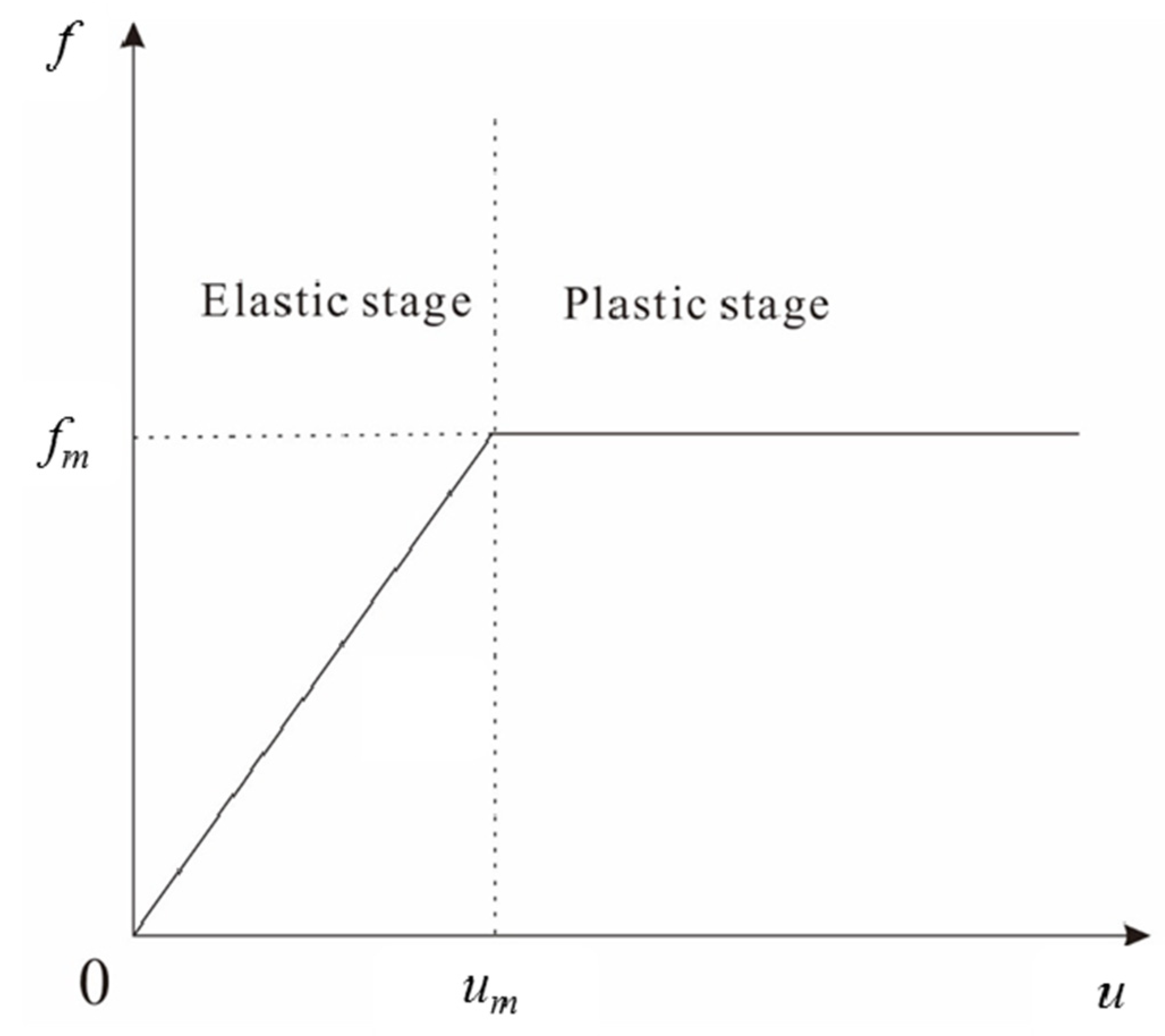
2.1. Effective Stress Method (ESM)

The effective stress method (ESM) was first proposed by Johannessen and Bjerrum [25]. Pile skin friction is calculated based on the ESM, the expression formula of maximum skin friction, fm, is shown in Equation (1):
f m = β σ v
where fm is the maximum skin friction unit pile depth, β is the empirical factor, which is influenced by the nature of surrounding soil of pile, β = (1 − sinφ’)tanδ for normally consolidation soil, β = (1 − sinφ’)OCR0.5tanδ for overconsolidated soil, φ’ is the effective friction angle, OCR is the overconsolidated ratio, and δ is the friction angle of the pile–soil interface [14]. They also can be determined based on field test as shown in Table 1. σv′ is the mean vertical effective stress of surrounding soil.
The relative settlement, which is the vertical displacement difference between soil and pile, varies linearly with depth, as shown in Figure 1. Sp, Ss, and Spl are the settlements of pile, soil, and pile bottom, respectively. L is the length of pile, while h is the embed depth. The relationship between the skin friction of pile, f, and the relative settlement of pile soil, u, is ideally elastoplastic. With the increase of u, f increases linearly. The elastic modulus, k, is constant. When u reaches the elastic critical value, um, f reaches its ultimate value, fm, u increases further, skin friction reaches plastic stage, and f is constant, as shown in Equation (2) and Figure 2.
f = { k u , u < u m f m , u > u m
Meanwhile, it assumes that the transition section of skin friction from maximum negative to positive is linear. The distribution of skin friction of a single pile is shown in Figure 3a,b, where r is the depth of neutral point and a and b are the depth range in which the NSF and PSF reach the limit value, respectively. The two cases of pile skin friction are discussed in detail, and the closed-form analytical solutions of axial force and displacement of pile shaft are given.
Case 1: When the relative settlement of pile soil at pile bottom is small, PSF does not reach the plastic stage and the resistance of pile bottom soil is N. The settlement of the surrounding soil is larger than that of the pile shaft within the depth range of r. The NSF occurs in this section and reaches the ultimate value within the depth range of a, as shown in Figure 3a.
In this case, the relative settlement of pile soil in the pile bottom, Spl < um, is shown in Figure 3a. According to the hypothesis mentioned above, the geometric relationship of pile soil settlement and governing equations can be given as Equation (3):
{ a = u 0 u m u 0 + S p l L r = u 0 u 0 + S p l L C β γ L 2 ( u 0 S p l ) ( u 0 u m ) 2 N u 0 ( u 0 + S p l ) = 0
where C is the perimeter of pile cross-section and u0 is the relative settlement of pile soil in ground surface. When the settlement and pile bottom reaction force satisfied the governing equations above, the plastic depth of skin friction and the location of neutral point can be determined.
According to the previous assumptions and boundary conditions, the axial force of pile shaft can be expressed in segments as Equation (4):
{ F ( z ) = C β γ 2 z 2 , 0 < z a F ( z ) = C β γ a 2 ( r a ) ( z 2 + 2 r z a r ) , a < z r F ( z ) = C β γ 2 ( r a L L r ( z r ) 2 ) , r < z L
where F(z) is the axial force of pile in depth of z, γ is the effective weight of surrounding soil, and z is the depth of soil. From the equation above, it can be seen that when z = r, the axial force reaches the maximum, which is in accord with the distribution characteristics of the axial force of the pile shaft in this condition.
With further consolidation of the surrounding soil, NSF and the drag load of the pile increases. With an increase in the pile shaft settlement, the ultimate PSF of the pile bottom occurs in the depth range of b, as shown in Figure 3b. When the relative settlement, Spl, reaches the elastic critical value, um, the PSF reaches the ultimate value. Similar geometric equations and the governing equation can be expressed as in Equation (5):
{ a = u 0 u m u 0 + S p l L r = u 0 u 0 + S p l L b = L 2 r + a C β γ ( r a ( L b ) ( L r b ) ( 2 L b ) b ) 2 N = 0
Similarly, the governing equation of the axial force can be obtained as Equation (6):
{ F ( z ) = C β γ 2 z 2 , 0 < z a F ( z ) = C β γ a 2 ( r a ) ( z 2 + 2 r z a r ) , a < z r F ( z ) = C β γ 2 ( r a a ( z r ) 2 r a ) , r < z L b F ( z ) = C β γ 2 ( r a a ( L b r ) 2 r a + z ( z L + b ) ) , L b < z L
The calculating parameters involved in the axial force equation of above two cases are easy to obtain at the engineering site.
In order to verify the applicability and rationality of the theoretical method, the ESM was used to calculate the skin friction of different single piles in reference [15]. The skin friction of a single pile in situ was calculated and compared to the measured value. There are two kinds of field test piles, one is a conventional single pile and the other is a single pile with an asphalt coated surface. Because asphalt reduces the friction between pile and soil, β = 0.1 for the coated pile, which is lower than the range of normal experience. For a normal uncoated pile, β = 0.25. Meanwhile, a two-dimensional (2D) pile–soil model was established by ABAQUS and the NSF of the single pile was also analyzed. The FEM model is a two-dimensional axisymmetric model with a vertical dimension of 40 m and a horizontal dimension of 10 m. The mesh of the soil near the pile was 0.1 m × 1 m, while the mesh of the soil at the border was 1 m × 1 m. The mesh size gradually increased outward. The friction coefficient was μ = 0.1 for the coated pile, and μ = 0.25 for the normal uncoated pile in the FEM model. The parameters involved in the calculation and numerical simulation are shown in Table 2 and Table 3. The results are shown in Figure 4. The compressibility of the soil layer in the field test was relatively large, which had an obvious negative friction resistance effect on the pile shaft. Both the test data and calculation results reflect this phenomenon. The compressibility of the soil within the range of 0–10 m should be improved, with methods such as grouting. Furthermore, a general agreement among the results of the ESM results, FEM results and field measurements demonstrates that the calculation method of pile side friction presented in this paper is reliable, so the present method and the 2D FEM model can be used to evaluate and analyze the pile skin friction.

2.2. Parametric Analyses of NSF

The NSF of a single pile is influenced by several parameters. Some of these influencing factors can be concluded as the consolidation time, friction coefficient, drainage condition, consolidation pressure, and pressure ratio between the pile top and soil surface. To further investigate the effect of the above mentioned parameters on NSF, a 2D axisymmetric FEM model with a vertical dimension of 30 m and a horizontal dimension of 20 m were established, as shown Figure 5. The pile was 20 m length and the diameter was 1 m, as the width of the model is usually 20 times more than the pile diameter. Other parameters of the pile and soil are shown in Table 4. The elastic modules of the pile were set to 30,000 MPa due to the pile properties, which is not easily to deform. Similarly, the elastic modulus of consolidating layer was set to 5 MPa, while that of the bearing layer was set to 30 MPa, which is because the consolidating layer is soft and easily to be compressed while the bearing layer is relative stiffer. The location of the water stable was the soil surface. The consolidation pressure on the soil surface is p, and the applied pressure on pile top is Q. The Mohr–Coulomb model was used for the soil properties, and the elastic model was used for pile properties. A similar method was also used by Hanna and Sherif [26]. The problem was analyzed in three steps. First, in order to obtain the initial geo-stress field, the ‘geostatic’ command was invoked to make sure that equilibrium was satisfied between the layered soil and pile. Second, the ‘soils’ type was selected in the consolidation pressure step. In order to simulate the instantaneous loading, the step time was very short, 0.001 d, where ‘d’ is the consolidation time unit (day). All boundaries were undrained. Third, the excess pore water pressure was to dissipate by changing the boundary drainage conditions.

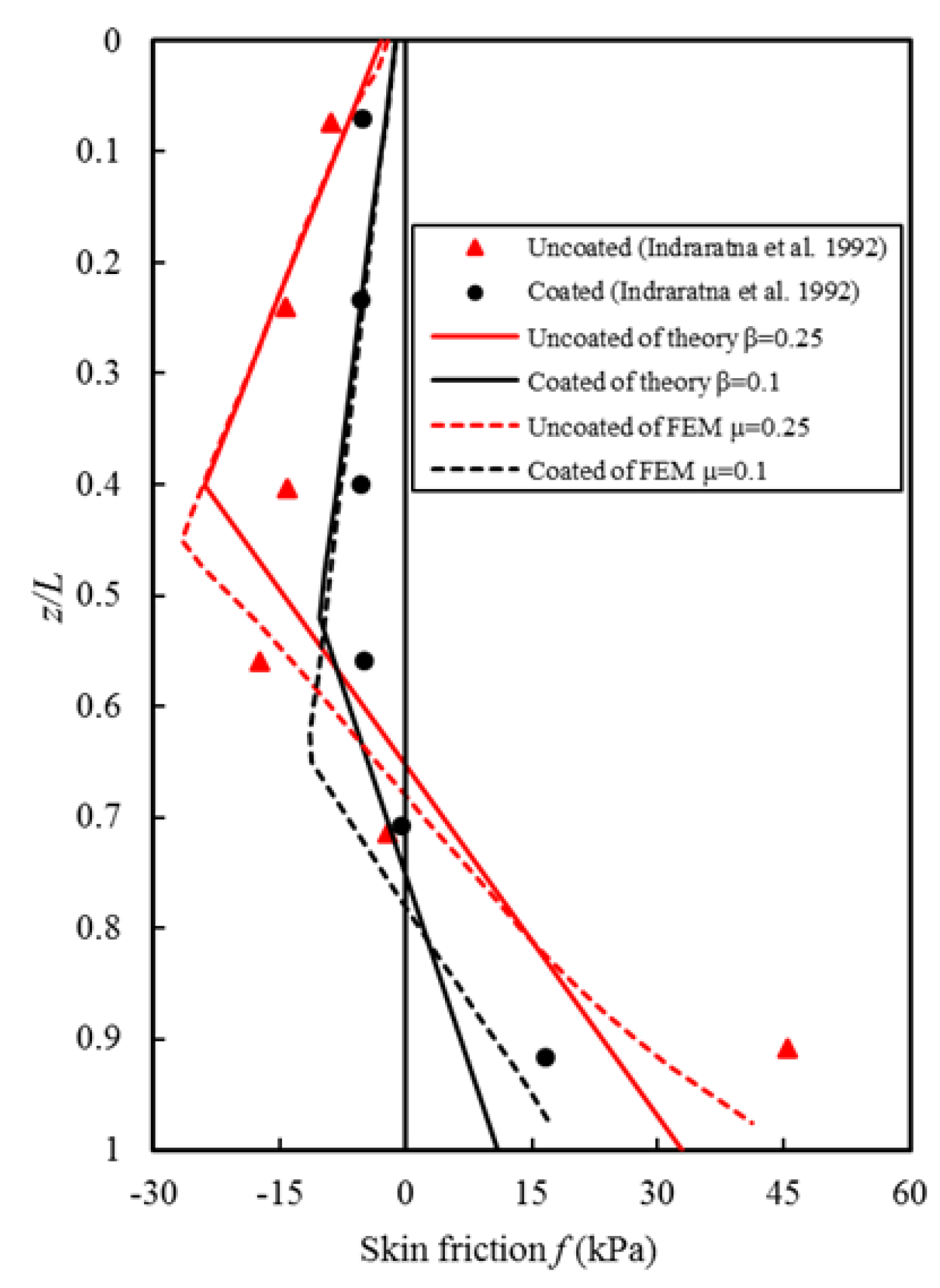
3. Results and Discussion

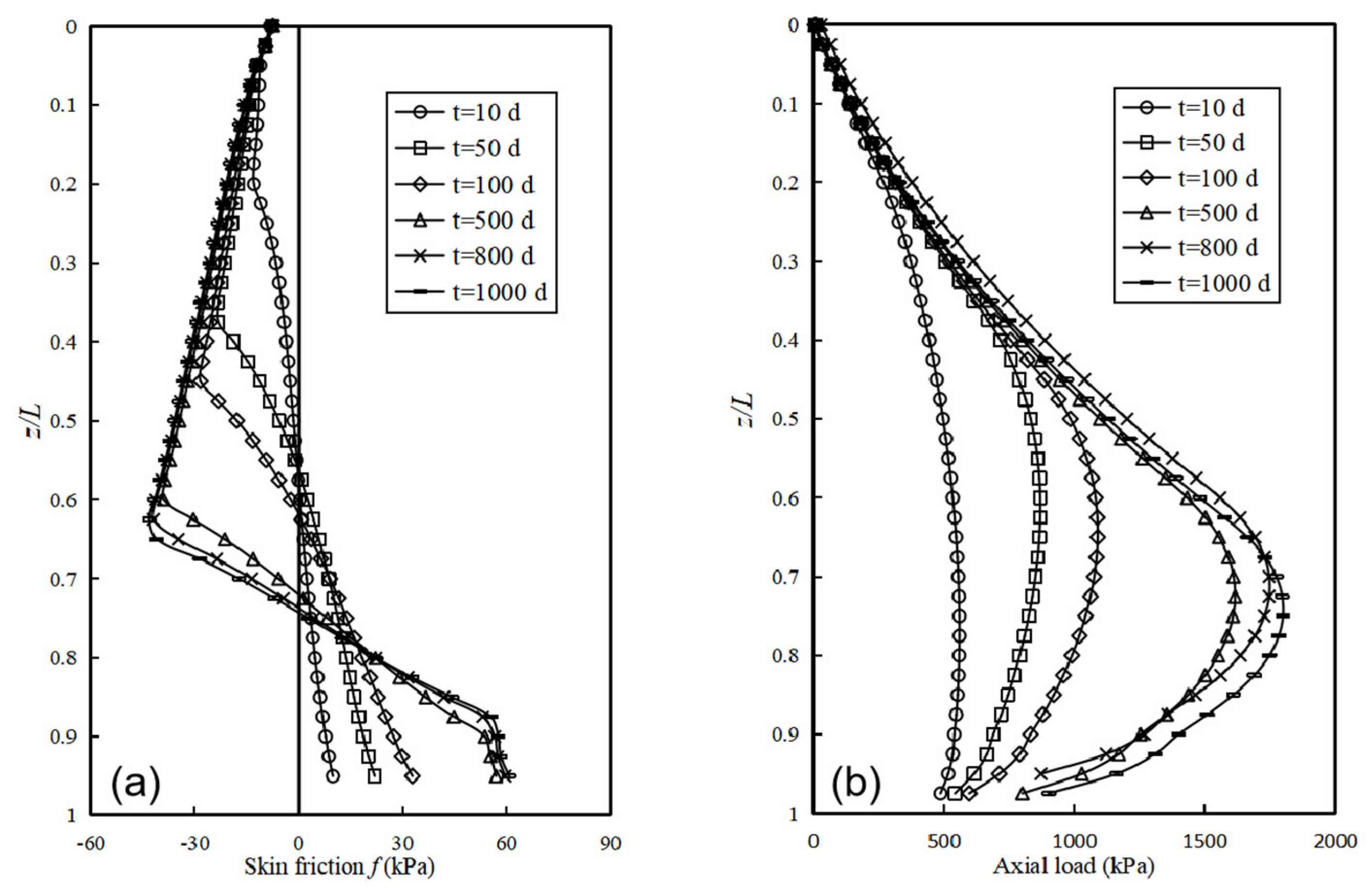
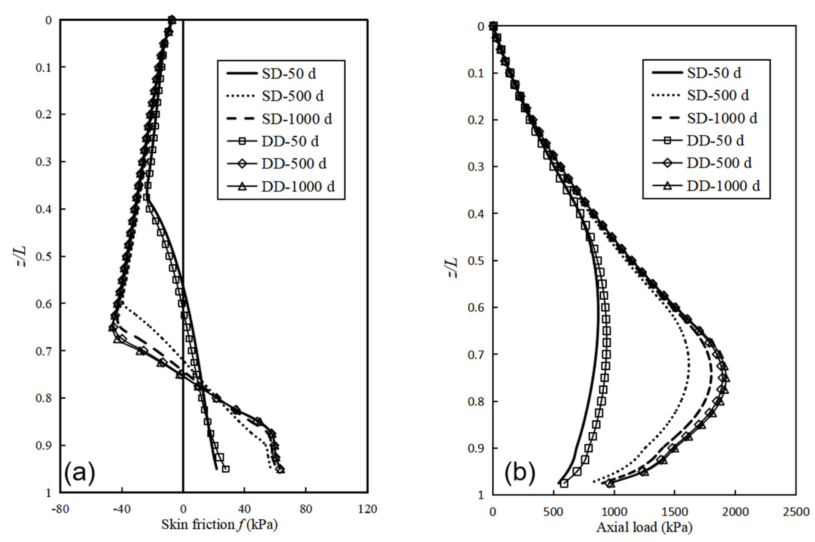
3.1. Effect of Consolidation Time

In this single drainage condition, SD, the effect of consolidation time on the NSF and axial load of pile is illustrated in Figure 6. In this analysis process, the consolidation pressure, p, is 100 kPa. With the increase of consolidation time, t, pore water discharges and pore water pressure dissipate gradually. The friction coefficient was constant, so the slope of fully mobilized skin friction versus depth was constant, as expected in the ESM above. It should be noted that the slope is relatively big when the consolidation time is short. It is believed that the friction coefficient of the pile–soil interface is reduced by water-bearing high pressure in pore. With an increase in consolidation time, the magnitude of skin friction and position of neutral point increased continuously, as shown in Figure 6a. The axial load of pile shaft versus the normalized depth is plotted in Figure 6b. With an increase in consolidation time, the drag-load caused by the settlement of soil increased. The location of the maximum axial load was the position of the neutral point, which is consistent with the theoretical analysis results.

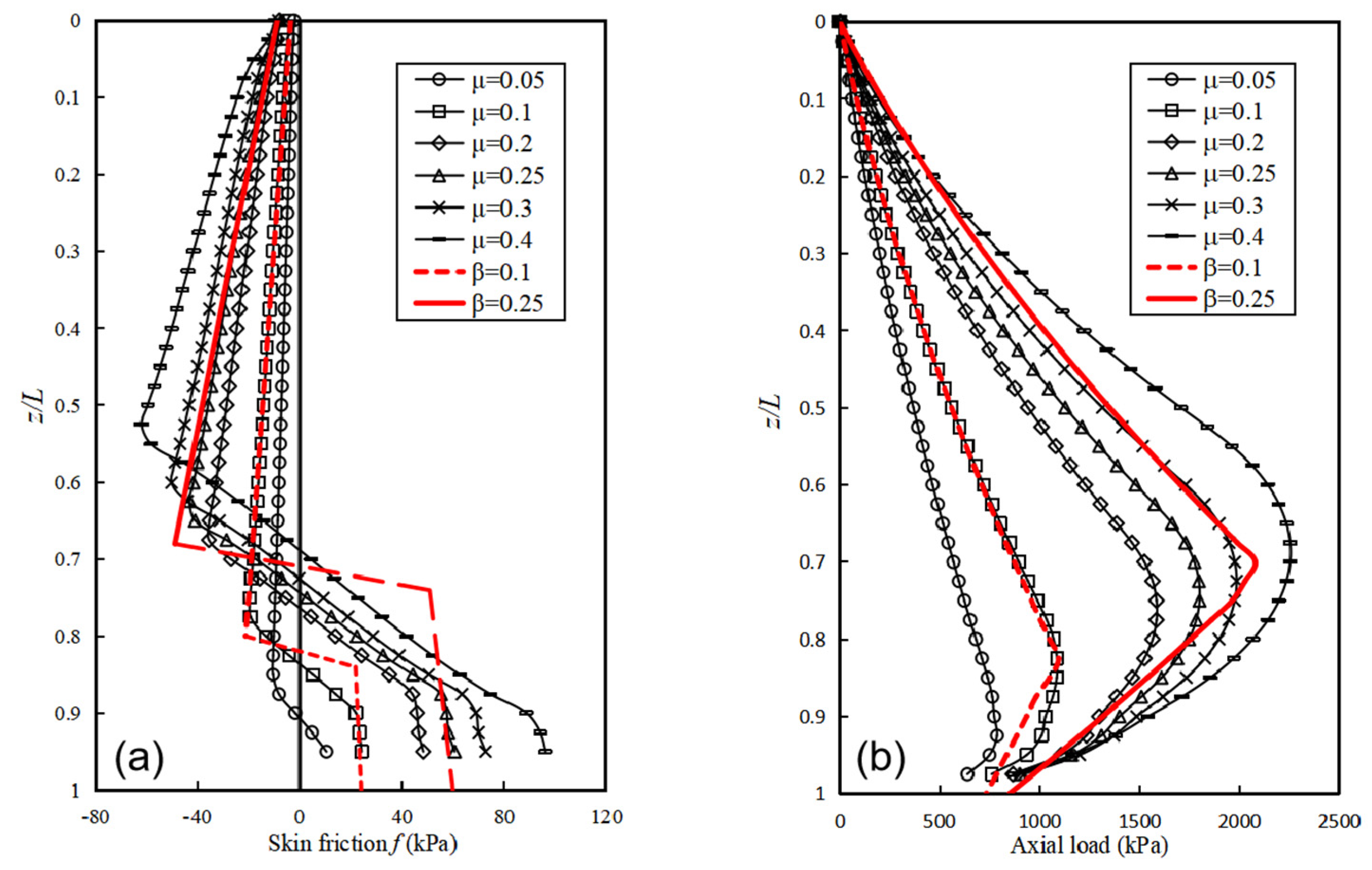
3.2. Effect of Friction Coefficient

The friction coefficient, μ, plays an important role in the bearing capacity of piles, especially for friction piles. The empirical value of friction coefficient has been mentioned above. In the absence of test data, a simple method is often used to determine the friction coefficient, μ = tanδ. Generally, the friction angle of the pile–soil interface, δ, ranges from 9° to 21°, which results in μ ranging from 0.15 to 0.4. To investigate the effect of the friction coefficient on skin friction and the axial load of the pile, μ = 0.05, 0.1, 0.2, 0.3, 0.4 were selected to analyze. The distribution of skin friction and axial load versus normally depth are plotted in Figure 7a,b, respectively.
Figure 7a shows that with an increase in friction coefficient, the NSF and PSF increased, and the location of neutral point decreased. As expected in the ESM above, with increases in the friction coefficient, the slope of fully mobilized NSF versus depth decreased. It also shows the distribution of skin friction of theoretical calculation by ESM for β = 0.1 and β = 0.25, with a red dash line, considering the surcharge in the soil surface. Comparing to the results of the FEM, fully mobilized NSF matches the theoretical value. However, there is a deviation in the range of fully mobilized PSF, and the larger the friction coefficient, the greater the deviation. This may be due to the fact that the deformation of soil is not linear, and the relative displacement of pile and soil near the pile bottom was smaller than the theoretical hypothesis. The larger the friction coefficient is, the more significant the non-linear deformation of the soil below the neutral point is.
Figure 7b shows that with an increase in the friction coefficient, the maximum axial load of pile increased. The theoretical values of the corresponding axial forces for β = 0.1 and β = 0.25 are also shown. The bigger the friction coefficient is, the larger the deviation between ESM value and FEM value is. The reasons are described above. It is well known that the larger the friction coefficient is, the greater the settlement constraint of pile on soil is, and the greater the drag-load is in the same consolidation conditions. The normalized position of the neutral point, r/L, and the normalized axial load, Fmax/p, varied with friction coefficient are plotted in Figure 8, where the best fitting equations are also given.

3.3. Effect of Drainage Condition

The essence of soil consolidation is the dissipation of excess pore water pressure. Therefore, drainage conditions have an important influence on the rate of consolidation. In this section, both of the soil surface and bottom can drain, which is dual drainage (DD). The effect of the drainage condition on skin friction and axial load of pile are shown in Figure 9a,b, respectively. When the consolidation time is relative short, the distribution of skin friction and the axial load of pile in SD condition is almost same as that in DD condition. When t = 500 d, both the skin friction and the axial load of pile in SD condition are obviously smaller than that in the DD condition due to the different degree of consolidation, as mentioned above. When t = 1000 d, the difference between them is narrowed because the degree of consolidation is getting close. It is worth noting that the maximum axial load of the pile in DD conditions is larger. It is believed that a larger pile settlement occurs in dual drainage conditions. In the case of a single drainage condition, SD, the water seeps upward, which produces an upward seepage force on the soil particles and the soil has an upward tendency to move. However, in the case of dual drainage, DD, the soil has a downward movement trend because part of the water seeps downward and the pile draft is subjected to downwards drag force. Thus, the settlement increases.

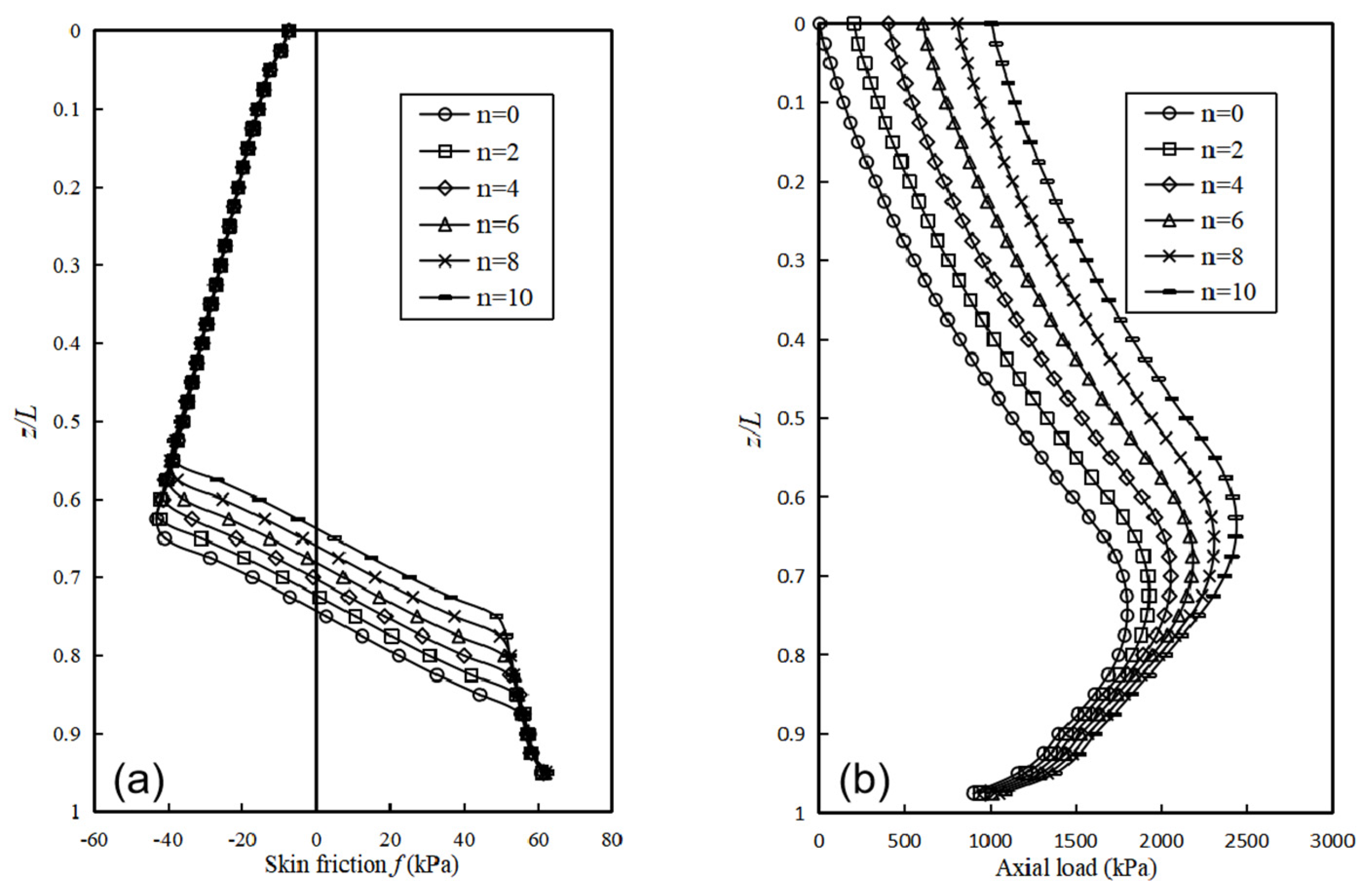
3.4. Effect of Consolidation Pressure

Figure 10a shows the effect of consolidation pressure, p, on the skin friction of pile. As we can see, the slope of fully mobilized NSF and PSF versus depth were parallel in different consolidation pressures due to the same friction coefficient used. When p = 50 kPa, the PSF did not reach the ultimate value, which belongs to case one, as mentioned in Section 2.1. Although the consolidation pressure had a great influence on the skin friction distribution, it had little effect on the location of neutral point, which is consistent with the conclusion of Liu et al. [14]. The normalized neutral point changed from 0.62 to 0.67 under the consolidation pressure increment from 25 kPa to 400 kPa in their studies. Similarly, it changed from 0.71 to 0.77 in this paper. This discrepancy is owing to the face that the piles in their studies were based on a much softer bearing layer. The results measured of the pile founded on a much stiffer bearing layer in the field was 0.83 to 0.95 [27]. Interestingly, at the depth of 0.775 L, the PSF of pile under different consolidation pressure was very close.
The axial load of pile versus normalized depth under different consolidation pressures are plotted in Figure 10b. Obviously, with the increase of consolidation pressure, the maximum axial load of pile increases. However, the increment of maximum axial force was not proportional to the increment of consolidation pressure. The maximum axial load increased by 43.8% when p increased from 50 kPa to 100 kPa, by 44% when p increased from 100 kPa to 200 kPa, and only by 19% when p increased from 300 kPa to 400 kPa. When the increment of consolidation pressure was constant, the pressure level was higher and the increase in the rate of maximum axial load was lower.

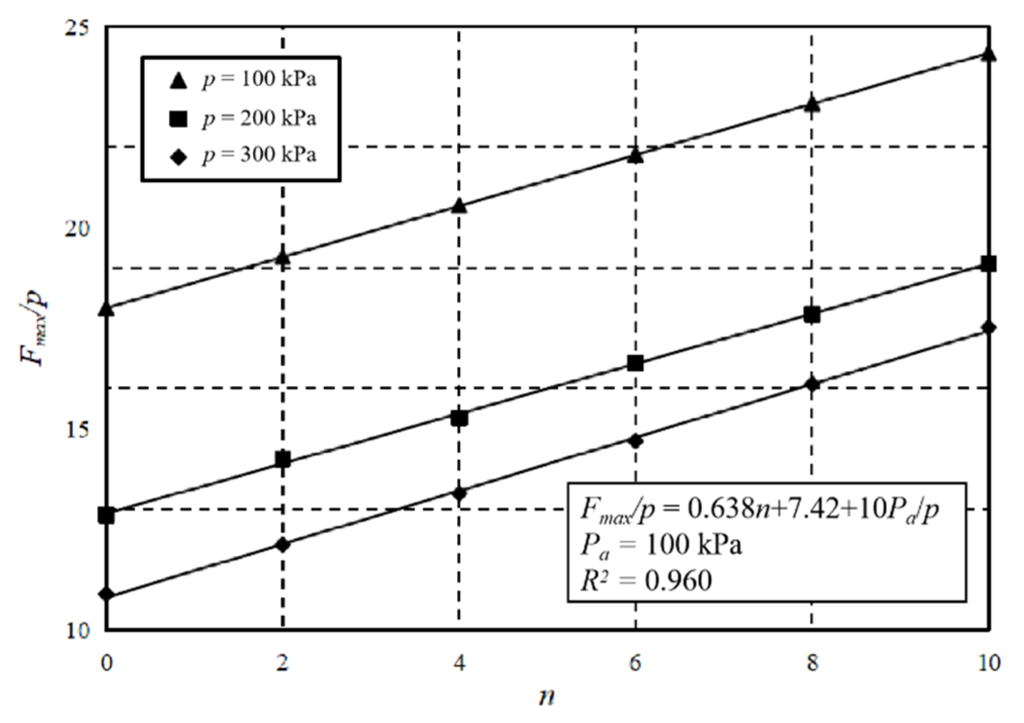
3.5. Effect of Pressure Ratio

The effect of the pressure ratio, n = Q/p, on skin friction and the axial load of the pile are shown in Figure 11a,b, respectively. As we can see, the slopes of fully the mobilized NSF versus normalized depth are the same under different pile top loads, as expected in the ESM, which is due to the same friction coefficient used. However, the position of the neutral point increased with the increase of Q, enhancing the settlement of the pile and decreasing the relative settlement between the pile and soil, thus reducing the depth of fully mobilized NSF. The axial load of the pile versus the normalized depth are plotted in Figure 11b. Obviously, the effect of the pile top pressure on the axial load decreased as the depth increased. It is believed that pile top load reduces the relative settlement of pile soil in NSF section, while enhances it in PSF section, which causes the total NSF value to reduce and the total PSF value to raise. The pile top pressure is counteracted by the PSF before it reaches the bottom of the pile. For a typical friction pile, when the increase of pile top pressure is constant, the adjusted magnitude of skin friction is the same, which also explains the parallelism of the negative and positive friction transition section.
The normalized maximum axial load, Fmax/p, and pressure ratio, n, show a good linear relationship, as shown in Figure 12, where the best fitting line is given. As we can see, the fitting curves of Fmax/p versus n are parallel to each other under different consolidation pressures, where the slopes are around 0.63. That means the maximum axial load, Fmax, was mainly affected by the applied pressure, Q.

4. Conclusions

In this paper, a simple theory model was developed to describe the distribution of skin friction of pile based on ESM. The measured data of an in situ test proved the applicability of this present method. FEM was also used to investigate the effect of consolidation time, friction coefficient, drainage condition, consolidation pressure, and pressure ratio on NSF and axial load of single pile.
It was found that the position of the neutral point changed significantly with the consolidation time and friction coefficient, and the best fitting line of the neutral point and friction coefficient was given. Drainage conditions have a significant effect on consolidation time but have only a slight influence on the position of the neutral point and the maximum axial load. Consolidation pressure has a slight influence on the position of the neutral point. Meanwhile, a good linear relationship between the position of neutral point and pressure ratio was observed. The axial load of the pile is an important parameter in pile foundation design. NSF significantly enhances the axial force of piles, which is influenced mainly by the friction coefficient, consolidation pressure, and pressure ratio. Furthermore, under different consolidation pressures, the normalized maximum axial load, Fmax/p, of the pile shaft had a good linear relationship with the pressure ratio, n, in which the slopes were the same and the unified fitting equation was given. The theoretical calculation by ESM and fitting equations should be combined for practice.

Author Contributions

Conceptualization, Y.W. and L.M.; methodology, Y.W., Y.R., J.L. and L.M.; software, Y.W., Y.R., J.L. and L.M.; validation, Y.R. and J.L.; formal analysis, Y.W., Y.R., J.L. and L.M.; investigation, Y.W., Y.R., J.L. and L.M.; resources, Y.W. and L.M.; data curation, Y.R. and J.L.; writing—original draft preparation, Y.R. and L.M.; writing—review and editing, Y.W. and J.L.; visualization, Y.R. and L.M.; supervision, Y.W.; project administration, L.M.; funding acquisition, L.M. All authors have read and agreed to the published version of the manuscript.

Funding

This research was funded by the Department of Education of Anhui Province, grant number KJ2020A0080 and KJ2021A0862 and by the Ministry of Science and Technoligy of the People’s Republic of China, grant number B210202034, B200204036 and B200204032.

Institutional Review Board Statement

Not applicable.

Informed Consent Statement

Not applicable.

Data Availability Statement

The data presented in this study are available in article.

Acknowledgments

The authors would like to acknowledge the financial support of Key projects of natural science research in colleges and universities of Anhui Province (KJ2020A0080 and KJ2021A0862) and the Fundamental Research Funds for the Central University (B210202034, B200204036 and B200204032).

Conflicts of Interest

The authors declare no conflict of interest.

References

  1. Madhav, M.R.; Sharma, J.; Sivakumar, V. Settlement of and load distribution in a granular piled raft. Gé;oméch. Eng. 2009, 1, 97–112. [Google Scholar] [CrossRef]
  2. Wu, Y.D.; Liu, J.; Chen, R. An analytical analysis of a single axially-loaded pile using a nonlinear softening model. Géoméch. Eng. 2015, 8, 769–781. [Google Scholar] [CrossRef]
  3. Ko, J.; Cho, J.; Jeong, S. Nonlinear 3D interactive analysis of superstructure and piled raft foundation. Eng. Struct. 2017, 143, 204–218. [Google Scholar] [CrossRef]
  4. Bakholdin, B.V.; Berman, V.I. Investigations of negative skin friction on piles and suggestions on its calculation. Soil Mech. Found. Eng. 1974, 11, 238–244. [Google Scholar] [CrossRef]
  5. Kim, K.D.; Plodpradit, P.; Kim, B.J.; Sinsabvarodom, C.; Kim, S. Interface behavior of grouted connection on monopile wind turbine offshore structure. Int. J. Steel Struct. 2014, 14, 439–446. [Google Scholar] [CrossRef]
  6. Zhao, M.H.; He, W.; Cao, W.G. Study on calculation of negative skin friction resistance on piles. Rock Soil Mech. 2004, 25, 1442–1446. [Google Scholar] [CrossRef]
  7. Chen, R.; Zhou, W.; Chen, Y. Influences of soil consolidation and pile load on the development of negative skin friction of a pile. Comput. Geotech. 2009, 36, 1265–1271. [Google Scholar] [CrossRef]
  8. Kim, H.J.; Mission, J.L.C. Negative skin friction on piles based on finite strain consolidation theory and the nonlinear load transfer method. KSCE J. Civ. Eng. 2009, 13, 107–115. [Google Scholar] [CrossRef]
  9. Wong, K.S.; Teh, C.I. Negative Skin Friction on Piles in Layered Soil Deposits. J. Geotech. Eng. 1995, 121, 457–465. [Google Scholar] [CrossRef]
  10. Chow, Y.K.; Chin, J.T.; Lee, S.L. Negative skin friction on pile groups. Int. J. Numer. Anal. Methods Géoméch. 1990, 14, 75–91. [Google Scholar] [CrossRef]
  11. Li, X.Y.; Bai, X.Y.; Zhang, M.Y. Study on bearing capacity characteristics of rock socketed short pile in weathered rock site. J. Eng. Res. 2019, 7, 76–89. [Google Scholar]
  12. Rajan, P.M.; Krishnamurthy, P. Termination Criteria of Bored Pile Subjected to Axial Loading. Indian Geotech. J. 2019, 49, 566–579. [Google Scholar] [CrossRef]
  13. Ai, Z.Y.; Chen, Y.F. FEM-BEM coupling analysis of vertically loaded rock-socketed pile in multilayered transversely isotropic saturated media. Comput. Geotech. 2020, 120, 103437. [Google Scholar] [CrossRef]
  14. Liu, J.; Gao, H.; Liu, H. Finite element analyses of negative skin friction on a single pile. Acta Geotech. 2012, 7, 239–252. [Google Scholar] [CrossRef]
  15. Indraratna, B.; Balasubramaniam, A.S.; Phamvan, P.; Wong, Y.K. Development of negative skin friction on driven piles in soft Bangkok clay. Can. Geotech. J. 1992, 29, 393–404. [Google Scholar] [CrossRef]
  16. Xing, H.; Liu, L. Field Tests on Influencing Factors of Negative Skin Friction for Pile Foundations in Collapsible Loess Regions. Int. J. Civ. Eng. 2018, 16, 1413–1422. [Google Scholar] [CrossRef]
  17. Lv, Y.; Liu, H.; Ding, X.; Kong, G. Field Tests on Bearing Characteristics of X-Section Pile Composite Foundation. J. Perform. Constr. Facil. 2012, 26, 180–189. [Google Scholar] [CrossRef]
  18. Yan, W.M.; Sun, T.K.; Tham, L.G. Coupled-Consolidation Modeling of a Pile in Consolidating Ground. J. Geotech. Geoenvironmental Eng. 2012, 138, 789–798. [Google Scholar] [CrossRef]
  19. Yao, W.; Liu, Y.; Chen, J. Characteristics of Negative Skin Friction for Superlong Piles under Surcharge Loading. Int. J. Géoméch. 2012, 12, 90–97. [Google Scholar] [CrossRef]
  20. Lam, S.Y.; Ng, C.W.W.; Poulos, H.G. Shielding Piles from Downdrag in Consolidating Ground. J. Geotech. Geoenviron. Eng. 2013, 139, 956–968. [Google Scholar] [CrossRef]
  21. Cao, W.; Chen, Y.; Wolfe, W.E. New Load Transfer Hyperbolic Model for Pile-Soil Interface and Negative Skin Friction on Single Piles Embedded in Soft Soils. Int. J. Géoméch. 2014, 14, 92–100. [Google Scholar] [CrossRef]
  22. Ma, L.; Wang, Y.K. Calculation and analysis of negative skin of monopile applied for offshore wind turbine. Mar. Georesources Geotechnol. 2015, 35, 275–280. [Google Scholar] [CrossRef]
  23. Haigh, S.K.; Madabhushi, S.G. Centrifuge modelling of pile-soil interaction in liquefiable slopes. Géoméch. Eng. 2011, 3, 1–16. [Google Scholar] [CrossRef]
  24. Muhammed, R.D.; Canou, J.; Dupla, J.-C.; Tabbagh, A. Laboratory Study of Local Clay-Pile Friction Evolution for Large Numbers of Cycles. In Lecture Notes in Civil Engineering; Springer: Singapore, 2018; Volume 8, pp. 746–755. [Google Scholar] [CrossRef]
  25. Johannessen, I.J.; Bjerrum, L. Measurements of the compression of a steel pile to rock due to settlement of the surrounding clay. In Proceedings of the 6th International Conference on Soil Mechanics and Foundation Engineering, Montreal, QC, Canada, 8–15 September 1965; pp. 261–264. [Google Scholar] [CrossRef] [Green Version]
  26. Hanna, A.M.; Sharif, A. Drag Force on Single Piles in Clay Subjected to Surcharge Loading. Int. J. Géoméch. 2006, 6, 89–96. [Google Scholar] [CrossRef]
  27. Comodromos, E.; Bareka, S.V. Evaluation of negative skin friction effects in pile foundations using 3D nonlinear analysis. Comput. Geotech. 2005, 32, 210–221. [Google Scholar] [CrossRef]
Figure 1. The relative settlement of pile soil.
Applsci 12 04125 g001
Figure 2. The ideal elastoplastic relationship between skin friction of the pile and the relative settlement of pile soil.
Applsci 12 04125 g002
Figure 3. Distribution of skin friction of a single pile: (a) Case 1; (b) Case 2.
Applsci 12 04125 g003
Figure 4. Comparison among ESM, FEM and measured data [15].
Applsci 12 04125 g004
Figure 5. 2D axisymmetric model used in the analysis.
Applsci 12 04125 g005
Figure 6. Effect of consolidation time on (a) skin friction and (b) axial load.
Applsci 12 04125 g006
Figure 7. Effect of friction coefficient on (a) skin friction (b) and axial load.
Applsci 12 04125 g007
Figure 8. Normalized maximum axial load and normalized position of neutral point versus friction coefficient.
Applsci 12 04125 g008
Figure 9. Effect of drainage condition on (a) skin friction and (b) axial load.
Applsci 12 04125 g009
Figure 10. Effect of consolidation pressure on (a) skin friction and (b) axial load.
Applsci 12 04125 g010
Figure 11. Effect of pressure ratio on (a) skin friction (b) and axial load.
Applsci 12 04125 g011
Figure 12. Normalized maximum axial load versus pressure ratio.
Applsci 12 04125 g012
Table 1. The value range of empirical factor β.
Soilβ
Clay0.2–0.25
Silty soil0.25–0.35
Sand0.35–0.5
Table 2. The parameters of consolidating layer.
Depth
(m)
Weight (kN/m3)Elastic Modulus (MPa)Poisson’s RatioCohesion
(kPa)
Friction Angle (°)Coefficient of Permeability (×10−10 m/s)
0–41850.232678.2
4–101850.26256.37
10–201850.215253.04
20–186.50.26234.31
Table 3. The parameters of pile.
Length (m)Diameter (m)Weight (kN/m3)Elastic Modulus (MPa)Poisson’s Ratio
250.42030,0000.33
Table 4. The parameters of the pile–soil system used in FEM model.
ComponentPropertiesValue
PileLength (m)20
Diameter (m)1
Weight (kN/m3)18
Elastic modulus (MPa)30,000
Poisson’s ratio0.15
Consolidating layerWeight (kN/m3)18
Poisson’s ratio0.3
Elastic modulus (MPa)5
Cohesion (kPa)5
Friction angle (°)20
Void ratio1
Coefficient of permeability (×10−4 m/d)6.8
Bearing layerWeight (kN/m3)18
Poisson’s ratio0.3
Elastic modulus (MPa)30
Cohesion (kPa)5
Friction angle (°)30
Void ratio1
Coefficient of permeability (×10−4 m/d)6.8
InterfaceElastic critical value of relative settlement of pile soil (mm)5
Publisher’s Note: MDPI stays neutral with regard to jurisdictional claims in published maps and institutional affiliations.

