Article

Sodium-Conducting Ionic Liquid Electrolytes: Electrochemical Stability Investigation

by
Giovanna Maresca
1,2,*,
Paolo Casu
1,3,
Elisabetta Simonetti
1,
Sergio Brutti
3 and
Giovanni Battista Appetecchi
1,*
1
ENEA (Italian National Agency for New Technologies, Energy and Sustainable Economic Development) Materials and Physicochemical Processes Technical Unit (MATPRO), Via Anguillarese 301, 00123 Rome, Italy
2
Department of Basic and Applied Sciences of Engineering, La Sapienza University of Rome, Piazzale Aldo Moro 5, 00185 Rome, Italy
3
Department of Chemistry, La Sapienza University of Rome, Piazzale Aldo Moro 5, 00185 Rome, Italy
*
Authors to whom correspondence should be addressed.
Appl. Sci. 2022, 12(9), 4174; https://doi.org/10.3390/app12094174
Submission received: 29 March 2022 / Revised: 12 April 2022 / Accepted: 18 April 2022 / Published: 21 April 2022
(This article belongs to the Special Issue Innovative Materials for Batteries)

Abstract

:
Sodium-conducting electrolytes, based on the EMIFSI, EMITFSI, N1114FSI, N1114TFSI, N1114IM14, PIP13TFSI and PIP14TFSI ionic liquids, were investigated in terms of electrochemical stability through voltammetry techniques with the aim of evaluating their feasibility in Na-ion devices. Both the anodic and cathodic sides were studied. The effect of contaminants, such as water and/or molecular oxygen, on the electrochemical robustness of the electrolytes was also investigated. Preliminary cyclic voltammetry and charge-discharge tests were carried out in Na/hard carbon and Na/α-NaMnO2 half cells using selected ionic liquid electrolytes. The results are presented and discussed in the present paper.

1. Introduction

Rechargeable alkali metal-ion batteries, especially lithium-ion batteries (LIBs), currently represent the most efficient electrochemical energy storage system [1,2,3]. After the first commercialization in the 1990s, LIBs became the main high-power source for portable electronics devices [4,5,6]. The worldwide energy demand is constantly increasing for large-scale applications (i.e., electric vehicles (EVs) and stationary energy systems coupled to renewable power plants) [7], but the limited abundance of lithium, followed by a rise in the price of raw materials employed in LIBs [8,9,10], motivated the scientific community to earnestly study alternative materials with similar characteristics. Sodium-ion batteries (NIBs) are considered promising alternatives to LIBs [11,12] because of their much larger resource availability, lower cost and the similarity in the redox potentials of Na (2.71 V vs. H+/H2) and Li. Furthermore, the sodium-based battery chemistry allows use of an Al current collector, which is lighter and cheaper than Cu, thanks to the poor driving force of the Na/Al alloy compared to the favourable thermodynamics in the Li/Al case.
Similar to Li-ion devices, NIBs show safety problems strongly related to electrical/thermal abuses and the chemical and electrochemical stability of the cell components [13]. The use of volatile and flammable organic liquid electrolytes represent a severe safety drawback. A strategy to overcome this issue is the replacement of the conventional organic electrolytes with ionic liquids (ILs) (i.e., molten salts at room temperature or below) due to their intriguing properties, such as flame retarding, negligible vapour pressure, thermal-chemical-electrochemical stability and good ionic conductivity [14,15,16].
In previous work we demonstrated the excellent properties of sodium electrolyte systems based on different IL families, in terms of ion transport properties and thermal stability, which has never been investigated for Na batteries until now [17]. The investigated ILs were obtained by combining the 1-ethyl-3-methyl-imidazolium (EMI), trimethyl-butyl-ammonium (N1114) and N-alkyl-N-methyl-piperidinium (PIP1A) cations with the bis (fluorosulfonyl) imide (FSI), bis (trifluoromethylsulfonyl) imide (TFSI) and (nonafluorobutylsulfonyl) (trifluoromethylsulfonyl) imide (IM14) anions. Also, the IL materials were studied in the presence of sodium salts.
In this paper we thoroughly investigated the electrochemical stability of the synthetized IL electrolytes described above by voltammetry measurements, which has not been reported in the literature until now. The effect of humidity on anodic stability was also reported. Finally, preliminary cyclic voltammetry analysis and charge-discharge tests were run in NIB electrodes as hard carbon (HC) anodes and in monocline sodium manganite (α-NaMnO2 (NMO)) as cathodes [18,19].

2. Experimental Procedure

2.1. Materials and Methods

The ionic liquids, 1-ethyl-3-methylimidazolium bis (fluorosulfonyl) imide (EMIFSI), 1-ethyl-3-methylimidazolium bis (trifluoromethylsulfonyl) imide (EMITFSI), N-trimethyl-N-butyl-ammonium bis (fluorosulfonyl) imide (N1114FSI), N-trimethyl-N-butyl-ammonium bis (trifluoromethylsulfonyl) imide (N1114TFSI), N-trimethyl-N-butyl-ammonium (nonafluorobutylsulfonyl) (trifluoromethylsulfonyl) imide (N1114IM14), N-methyl-N-propylpiperidinium bis (trifluoromethylsulfonyl) imide (PIP13TFSI) and N-butyl-N-methylpiperidinium bis (trifluoromethylsulfonyl) imide (PIP14TFSI), were synthetized and purified according to an eco-friendly method, which has been described in detail elsewhere [17,20,21].
The Na-conducting electrolytes were prepared by dissolving the sodium salt, namely NaClO4 (Merck KGaA, Darmstadt, Germany, >99 wt.%) and NaTFSI (3M, Saint Paul, MN, USA, >99.9%), in the IL materials (NaX:IL mole ratio = 1:4) [17] by magnetic stirring for a few hours.
The carbon-based working electrodes were prepared by mixing 70 wt.% Super C45 (IMERYS, Bodio, Switzerland) and 30 wt.% Na-carboxymethylcellulose (CMC, Dow Wolff Cellulosics GmbH, Bomlitz, Germany) in deionized water. The obtained slurry was casted onto aluminium foil (20 μm thickness), and the aqueous solvent was allowed to extensively evaporate at room temperature for 24 h (within an extractor hood). Then, disks with a 10 mm diameter (and 50 μm thickness) were punched from the electrode tape and vacuum-dried (using an oil-free pump) at 150 °C (in a glass oven) overnight.
The HC and NMO, prepared according to a methodology reported in detail elsewhere [18,19], were punched as 10 mm diameter disks (supported on 20 μm thick Al foil), and then vacuum-dried at 120 °C overnight. The active material content is equal to 75 (HC) and 80 (NMO) wt.%, with a mass loading around 1.0 (HC) and 2.0 (NMO) mg cm−2. This corresponds to a capacity of 0.3 (HC, theoretical capacity equal to 300 mA h g−1) and 0.4 (NMO, theoretical capacity equal to 208 mA h g−1) mA cm−2.
Both the electrolyte and electrode materials, as well as the cell manufacturing, were stored and handled in an Ar-filled dry box (Jacomex, Dagneux, France, O2 and H2O level < 1 ppm).

2.2. Electrochemical Measurements

The electrochemical stability window was investigated by voltammetry analysis on Na metal cells, which were prepared using two-electrode Swagelok cells (diameter = 10 mm). Two glass fibre (WhatmanTM, Maidstone, UK) disk separators, soaked with a 0.1NaClO4-0.9IL electrolyte solution, were placed between a Na metal (American Elements, Los Angeles, CA, USA) coin and a Pt° (Merck KGaA, Darmstadt, Germany), carbon or HC-working electrode. Before sealing, the cells were subjected to a vacuum for 30 min to allow complete loading of the working electrode and separator by the viscous IL electrolyte.
A preliminary study on anodic stability was conducted by linear sweep voltammetry (LSV) on Na° cells, using Pt as the working electrode to define the anodic voltage cut-off (i.e., 4.6 V), which was applied as the benchmark. The LSV was run from the open circuit voltage (OCV) towards more positive voltage values at a scan rate of 1 mV s−1. Then, cyclic voltammetry (CV) tests were run using carbon-based (Super C45) working electrodes which allow much better simulation of the operative conditions in practical devices. The CV measurements were carried out by consecutively scanning the cell voltage between the OCV value and 4.6 V at a scan rate of 1 mV s−1.
The cathodic stability was investigated by CV analysis using HC as the working electrode by consecutively scanning the cell voltage between the OCV value and 0.01 V at a scan rate of 0.05 mV s−1.
Preliminary CV and cycling tests were performed in Na/HC and Na/NMO cells using selected IL electrolyte formulations (i.e., 0.1NaTFSI-0.9EMIFSI and 0.1NaTFSI-0.9N1114FSI). The cells were fabricated by sandwiching a sodium metal electrode coin (10 mm diameter), a glass fibre separator and an HC (or NMO) electrode in T-shape (Na/HC cells) or 2032 coin-type (Na/NMO) containers. The cells were kept under vacuum for 30 min to allow complete loading of the IL electrolyte into the electrode and the separator. A sodium metal reference electrode was used for the Na/HC cells subjected to cycling tests (i.e., the working electrode potential was recorded with respect to the reference because of the Na° overvoltage) [18].
The electrochemical tests were carried out between the 0.01–2.2 V (Na/HC) and 2.0–3.8 V (Na/NMO) voltage ranges using a Biologic (Seyssinet-Pariset, France) multi-channel battery system. CV and cycling measurements were performed at a 0.05 mV s−1 scan rate and 0.1 current rate, respectively.

3. Results and Discussion

All IL electrolytes show a moisture and halide content smaller than 2 and 5 ppm, respectively [17]. The corresponding thermal and ion transport properties, reported in previous work [17], are summarized in Table 1. The TFSI-based electrolytes are more thermally robust than the FSI ones. However, a thermal stability above 150 °C has been observed for all electrolyte samples. A room temperature ionic conductivity ranging between 10−4 and 10−3 S cm−1 has been recorded; in particular, the EMI and FSI electrolytes displayed the highest conduction values. To summarize, the IL electrolyte formulations reported here are relevant to the realization of safer and more reliable sodium battery systems and therefore, their characterization was extended to an electrochemical stability investigation.

3.1. Electrochemical Stability

3.1.1. Preliminary LSV Tests

The electrochemical stability window (ESW) of electrolytes is a crucial property to evaluate their applicability in real devices. LSV tests have been carried out on Na/Pt cells for the preliminary study of the anodic stability of each electrolyte formulation and the determination of the anodic potential cut-off in the following analysis. The LSV-specific current curves (normalized with respect to the geometric working electrode area) relative to the cell voltage are shown in Figure 1. All samples exhibit an electrochemical stability above 4.5 V vs. Na+/Na° backed up by a very low current flow (<5 μA cm−2) up to the anodic break down voltage; this is highlighted by a steep current increase due to the massive degradation of the electrolyte at high voltages. A few IL samples show weak features (i.e., not exceeding 10 μA cm−2) located from 2.0 to 3.0 V, which is probably ascribable to the irreversible oxidation of minor contaminants at the platinum working electrode. However, apart from this negligible electrochemical signal, no appreciable current increase is observed up to the massive degradation of the electrolyte. The electrolytes containing EMIFSI, N1114FSI, PIP13TFSI and PIP14TFSI as the ionic liquid are very stable up to about 5 V (vs. Na+/Na°). Meanwhile, the LSV curve of the N1114IM14 electrolyte does not exhibit a sudden current increase but rather, a moderate raise around 5.3 V. This behavior, previously observed in other IM14 ionic liquid electrolytes [22,23], is likely due to the ability of the IM14 anion species to form an insulating byproduct upon irreversible oxidation. The accumulation of these insoluble degradation species likely leads to a resistive and less electronically conductive passive layer on the working electrode surface. Based on LSV, a cut-off voltage equal to 4.6 V was adopted for the subsequent CV tests.

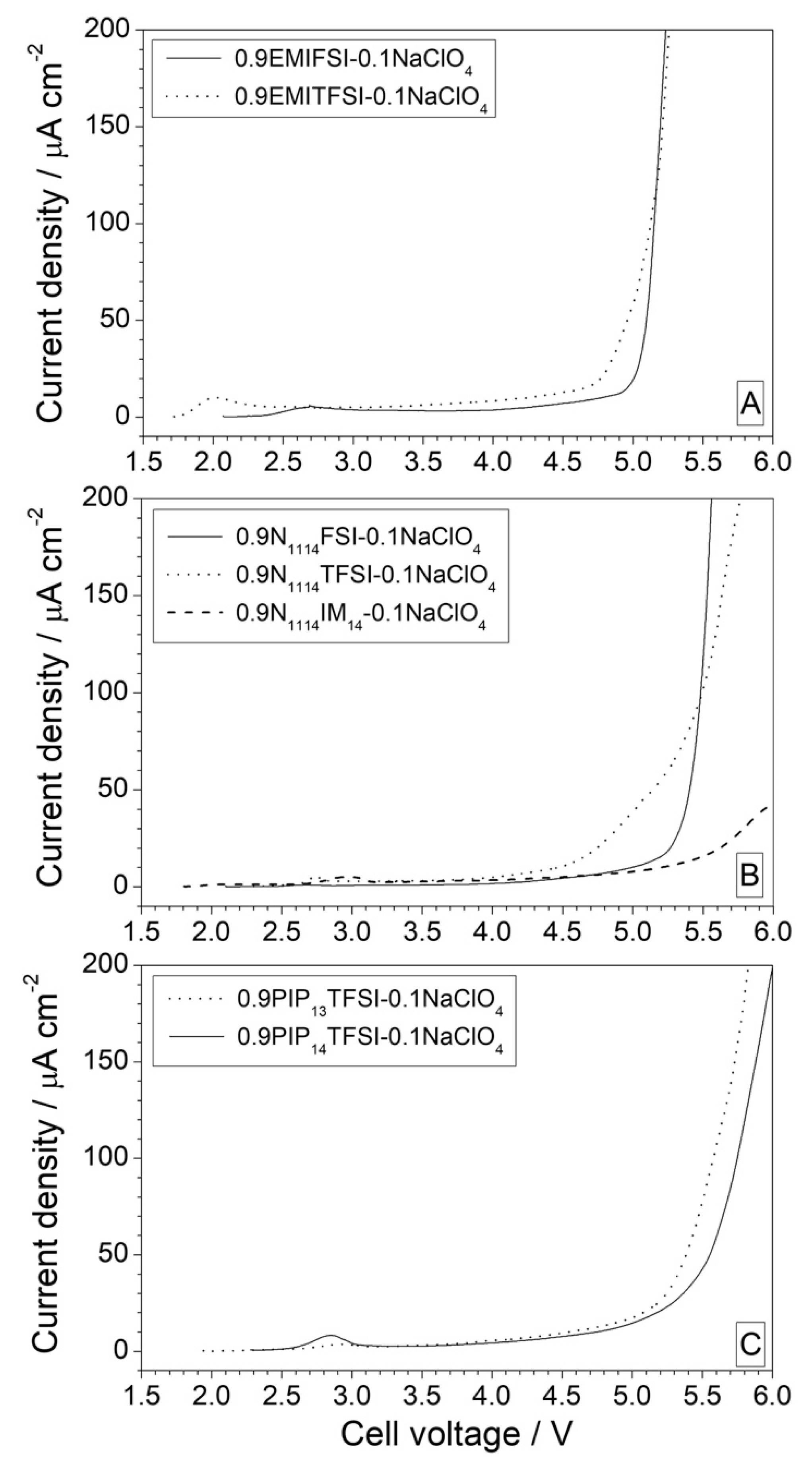
3.1.2. Anodic Stability

The ESW of the sodium-conducting electrolytes has been investigated by cyclic voltammetry tests in anodic and cathodic regions. The anodic stability was evaluated using carbon-based electrodes, in which the electrolytes are deliberately stressed up to 4.6 V in order to evaluate their robustness under severe operative conditions. The results, reported in Figure 2 as CV profiles, highlight a similar behavior for all investigated electrolytes. The undesired current increase of 20–50 μA cm−2 observed starting from 3–3.5 V in the first anodic scan (dotted traces), is limited to the first cycle as it disappears in the following cycles, where the current values never exceed 10 μA cm−2 up to 4.5 V. It is likely that the initial raise in current is due to the irreversible oxidation of impurities which, in our case, are fully degraded during the initial CV cycle despite their ability to catalyze the electrolyte decomposition [14]. Overall, the very low current values recorded up to the massive electrolyte degradation (mostly ascribable to the oxidation of the anion even if the cation may play a role) [14], which were highlighted by the rise onset around 4.5 V, confirms the high purity level of the IL electrolytes. The anodic limit voltage values (EA), taken when the current flow recorded during the CV measurements (Figure 2) achieves 10 (EA1) and 20 (EA2) μA cm−2, are summarized in Table 2. All IL electrolytes show good anodic stability well above 4 V vs. Na+/Na° (i.e., current values lower than 20 μA cm−2 are detected up to 4.6 V in the second anodic scan), fully matching the requirement for application in NIB systems. The electrolytes based on the EMI cation show current values higher than those of the IL samples consisting of piperidinium and N1114 cations and containing an analogous anion (FSI or TFSI), attributable (at least partially) to the greater ionic conduction of 1-ethyl-3-methylimidazolium [17]. However, as previously reported in the literature for similar types of ionic liquids [14], such behavior suggests that the nature of the cation plays an active role in the electrochemical oxidation process, although it is mainly attributable to the anion. Finally, voltametric measurements performed on piperidinium-based electrolytes (PIP13TFSI, PIP14TFSI) suggest that the anodic stability does not appear to be appreciably affected by the length of the alkyl side chain linked to the cation. To summarize, the stability towards oxidation of the investigated IL electrolytes follows the sequence TFSI > IM14 > FSI, in agreement with the results reported in the literature [23,24,25].

3.1.3. Effect of Contaminants on the Anodic Stability

The effect of the moisture content on the anodic stability of the IL electrolytes was investigated by means of CV measurements (Figure 3) performed on a selected sample (i.e., 0.1 NaClO4-0.9 EMITFSI), which had been previously exposed to the external atmosphere. The adsorbed moisture content was estimated around 200–300 ppm by Karl-Fisher coulomb-metric titrations. Comparing these results with those obtained on the analogous anhydrous (<2 ppm moisture) electrolyte (Figure 2), a current increase of about one order of magnitude is observed up to the fourth CV cycle with a decrease in the subsequent ones (Figure 3A). A similar behaviour is observed even if the voltametric measurements are run up to lower cut-off voltages (i.e., 4.2 (Figure 3B) and 4.0 V (Figure 3C)), despite the current value throughout the cell being significantly reduced. Therefore, the increase in current recorded in the initial cycles is attributable to the presence of humidity and/or molecular oxygen, which are both able to catalyse the degradation processes (oxidation) of the electrolyte and result in a decrease in electrochemical stability. Conversely, the decrease in the current value, recorded after a few voltametric cycles, is probably ascribable to the formation of an electronically insulating passive layer on the working electrode. These experimental findings, also reported in the literature for other ionic liquids [26,27], clearly show how the presence of impurities (such as humidity and/or oxygen) can negatively affect the properties of electrolytes, particularly with regard to electrochemical stability. Further investigation is in progress in our laboratories to promote better understanding of this issue.

3.1.4. Cathodic Stability

The electrochemical stability towards reduction was investigated by cyclic voltammetry (Figure 4) in the cathodic range on HC-working electrodes capable of reversibly intercalating sodium ions [18]. The CV measurements were carried out at a scan rate (0.05 mV s−1) considerably lower than the anodic ones (1 mV s−1) in order to promote the intercalation (de-intercalation) processes of sodium ions which, in cases of higher rates, may be hindered by kinetics. The FSI-based electrolytes (Figure 4A,E) show a large feature around 1 V that is present in the first cathode scan but absent in the following cycles and, therefore, is attributable to the formation of passive SEI constituted by the products coming from the electrolyte degradation [28,29,30] on the working electrode. Once formed, the SEI allows the reversible intercalation/de-intercalation of the Na+ cations [18]. The reversibility of the sodium intercalation process in the HC-working electrode is further highlighted by composite peaks that appear constant when cycling at about 0.5–0.6 V in the cathode scans, whereas a symmetric feature around 0.6–0.7 V is observed in the anode scans. No feature related to the IL electrolyte reduction is observed up to 0.01 V, clearly showing the possibility of reversibly intercalating sodium cations. This avoids irreversible degradation phenomena of the electrolyte components, indicating how the FSI anion can form optimal interphases even on sodium-intercalating electrodes. For instance, the ability of the FSI anion to form optimal protective films on LIB anodes, such as lithium metal, graphite and silicon, is widely reported in the literature [14]. Conversely, the electrolyte formulations containing the TFSI (Figure 4B–D,F) and IM14 (Figure 4G) anions do not exhibit any significant profile attributable to the intercalation process of Na+ ions within the HC electrode. The samples containing the ionic liquids EMITFSI (Figure 4B) and N1114TFSI (Figure 4F) show a clear profile around 0.5 V in the first cathode scan due to the formation of a passive film, while the subsequent anodic scan shows an even broader peak (in particular, EMITFSI) at about 1.5 V. However, this is more likely due to the oxidative processes catalysed by degradation products of the electrolyte, rather than the de-intercalation of sodium. Poor electrochemical activity is observed in the subsequent cycles. This behaviour may be due to the poor ability of the TFSI and IM14 anions to form stable, passive films on anodic active materials, as previously observed in lithium batteries [14]. Overall, almost negligible cathodic currents were measured using these IL electrolytes down to 0.01 V vs. Na+/Na, proving the strong electrochemical robustness towards reduction. To summarize, the anodic and cathodic CV measurements indicate a large electrochemical stability window up to 4.5 V and down to 0.01 V vs. Na for IL-based sodium-ion electrolytes.

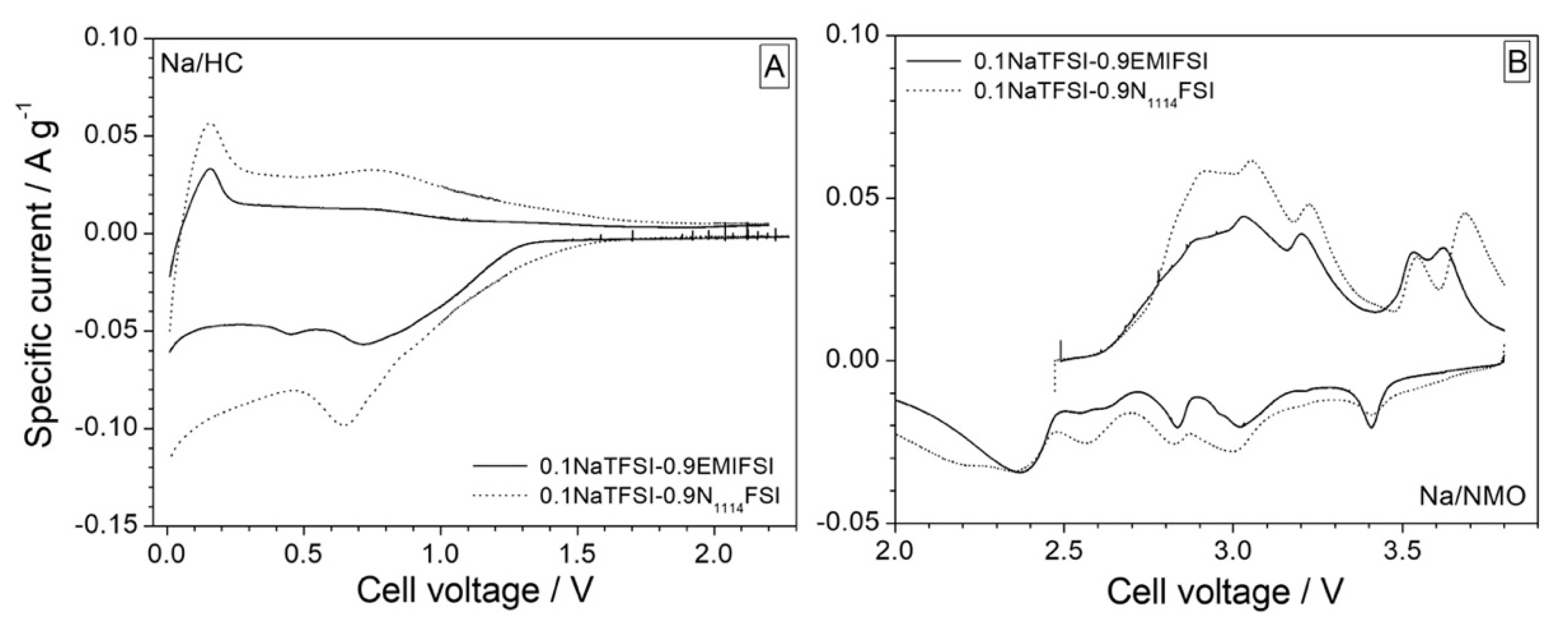
3.2. Preliminary Test in Na Half Cells

The EMIFSI and N1114FSI electrolytes both show an electrochemical stability window extending from 0.1 to 4.5 V vs. Na+/Na°, which is highly appealing for NIB systems. These electrolytes are also able to support the reversible intercalation of sodium ions in HC electrodes. Thanks to these features, both electrolyte formulations were selected for preliminary tests in Na/HC and Na/NMO half cells. The NaTFSI salt was preferable to NaClO4 in these tests in light of the unrealistic use of perchlorate-based solution in commercial electrolytes. In Figure 5, the CV test results of Na/HC (Figure 5A) and Na/NMO (Figure 5B) cells are shown. A large irreversible feature around 0.6 V vs. Na+/Na° is observed in the first cathodic scan of the hard carbon electrodes (Figure 5A) due to the SEI formation. HC electrodes exhibit a two-step storage mechanism: the first one is related to the sodium-ion intercalation into graphene layers above 200 mV (vs. Na+/Na°) and the second one is associated with the sodium insertion into micropores formed by the pseudo-graphitic domains with an oxidation state close to that of Na metal, which is detected below 200 mV [31,32,33,34]. The reversibility of the Na+ intercalation process is highlighted by the presence of two well-evidenced features around 0.15 and 0.7 V in the following anodic scan for both electrolytes. The first CV profile of NMO cathodes (displayed in Figure 5B) shows several features in both the anodic and cathodic scans, which is in line with the expected multi-stage de-sodiation/sodiation mechanism for this material [19,35]. As already described in the literature [35], the monoclinic α-NaMnO2 shows eight different oxidation peaks during the de-sodiation process, which are located at 2.59 V, 2.63 V, 2.73 V, 2.80 V, 2.97 V, 3.14 V, 3.48 V and 3.59 V. Whereas, the sodiation process involves five reduction peaks centered at 2.47 V, 2.62 V, 2.87 V, 3.08 V and 3.45 V. Nevertheless, the voltammograms of Figure 5B show only five separated peaks.
The cells containing the N1114FSI electrolyte (dotted traces) display a larger area under the CV profiles for both HC and NMO electrodes, supporting the greater reversibility of the electrochemical intercalation processes. No appreciable decomposition process is observed, so it can be concluded that these electrolytes are stable towards the electrode chemistries.
A preliminary evaluation of the electrochemical performance of HC (Figure 6A) and NMO (Figure 6B) electrodes in 0.1NaTFSI-0.9EMIFSI (solid traces) and 0.1NaTFSI-0.9N1114FSI (dotted traces) is reported in Figure 6, in terms of the initial voltage-capacity profile obtained at a 0.1C current rate. According to the CV results (Figure 5), the hard carbon electrode displays a two-step sodium incorporation process [18,31,36]: (i) a reduced pseudo-plateau around 0.10–0.15 V related to the sodium adsorption into the porosity of the structurally disordered carbonaceous material and (ii) a sloping curve at higher voltages, which accounts for the Na+ intercalation into pseudo-graphitic regions. During the first discharge, an irreversible capacity related to the SEI formation [34] is observed, namely 335 and 270 mA h g−1 for the EMIFSI and N1114FSI cells, respectively, which corresponds to a coulombic efficiency value of 27 (EMIFSI) and 39 (N1114FSI) %. The HC electrode is found to deliver an initial reversible capacity of 126 and 174 mA h g−1 in EMIFSI and N1114FSI electrolytes, respectively. These results are comparable with those obtained in organic standard electrolytes (i.e., 1 M NaTFSI in propylene carbonate with 3 wt.% fluoroethylene carbonate as an additive [18]).
The first charge-discharge voltage-capacity curve of the NMO electrodes is plotted in Figure 6B, which shows five plateaus (in both electrolyte formulations) corresponding to different phase transitions during the reversible Na+ intercalation process. This finding is in good agreement with the voltammetry results (Figure 5). An initial charge capacity around 190 mA h g−1 is observed for both IL electrolytes, corresponding to over 91% of the theoretical value of 208 mA h g−1 (i.e., 0.85 Na equivalent), as determined by Brutti and colleagues in monoclinic α-NaMnO2 [19]. However, a larger reversible capacity exceeding 160 mA h g−1 (vs. about 140 mA h g−1 in 0.1NaTFSI-0.9EMIFSI) is delivered in 0.1NaTFSI-0.9N1114FSI electrolytes, leading to higher initial coulombic efficiency (i.e., 83 (N1114FSI) vs. 73 (EMIFSI) %). These values are higher than those recorded in organic electrolyte solutions [18,19,32,34,35,36], making the EMIFSI and N1114FSI electrolyte formulations appealing for the realization of safer and more reliable sodium-ion battery systems.

4. Conclusions

The electrochemical stability of different sodium-conducting electrolyte families, based on the EMIFSI, EMITFSI, N1114FSI, N1114TFSI, N1114IM14, PIP13TFSI and PIP14TFSI ionic liquids, was investigated through voltammetry techniques with the aim of evaluating their feasibility in Na-ion devices. All IL electrolytes were found to be electrochemically stable within the 0.1–4.5 V (vs. Na+/Na°) voltage range, which was considered to be of particular interest for sodium battery systems. Moreover, EMIFSI and N1114FSI electrolytes allow the reversible sodium intercalation without any degradation process charged to the electrolyte, likely due to a stable SEI layer promoted by the FSI anion. The presence of impurities, such as water and/or oxygen, is able to negatively affect the electrochemical performance of the IL electrolytes. Preliminary electrochemical investigations, run through cyclic voltammetry and charge-discharge measurements, have shown good compatibility between the EMIFSI and N1114FSI electrolytes and hard carbon anodes and α-NaMnO2 cathodes, matching and/or overcoming the performance obtained in standard organic solutions. Therefore, EMIFSI- and N1114FSI-based electrolytes are of interest for the realization of highly safe, reliable and advanced sodium-ion electrochemical energy storage devices, which will be addressed in further studies.

Author Contributions

Conceptualization, G.B.A.; methodology, G.B.A. and G.M.; validation, G.M. and G.B.A.; formal analysis, G.M. and G.B.A.; investigation, G.M., P.C. and E.S.; data curation, G.M. and G.B.A.; writing—original draft preparation, G.M.; writing—review and editing, G.B.A. and S.B.; supervision, G.B.A. and S.B.; funding acquisition, G.B.A. and S.B. All authors have read and agreed to the published version of the manuscript.

Funding

This research was funded by the Italian Ministry of Economic Development (MISE) within the ENEA-MISE Program Agreement on Electric System Research. S.B. would like to thank the EU commission for the funding through the H2020 project number 101029608.

Institutional Review Board Statement

Not applicable.

Informed Consent Statement

Not applicable.

Data Availability Statement

No supportin data.

Conflicts of Interest

The authors declare no conflict of interest.

References

  1. Nitta, N.; Wu, F.; Lee, J.T.; Yushin, G. Li-ion battery materials: Present and future. Mater. Today 2015, 18, 252–264. [Google Scholar] [CrossRef]
  2. Palomares, V.; Serras, P.; Villaluenga, I.; Hueso, K.B.; Carretero-González, J.; Rojo, T. Na-ion batteries, recent advances and present challenges to become low cost energy storage systems. Energy Environ. Sci. 2012, 5, 5884–5901. [Google Scholar] [CrossRef]
  3. Kubota, K.; Dahbi, M.; Hosaka, T.; Kumakura, S.; Komaba, S. Towards K-Ion and Na-Ion Batteries as “Beyond Li-Ion”. Chem. Rec. 2018, 18, 459–479. [Google Scholar] [CrossRef] [PubMed]
  4. Yoshino, A. The Birth of the Lithium-Ion Battery. Angew. Chem. Int. Ed. 2012, 51, 5798–5800. [Google Scholar] [CrossRef] [PubMed]
  5. Scrosati, B. History of lithium batteries. J. Solid State Electrochem. 2011, 15, 1623–1630. [Google Scholar] [CrossRef]
  6. Nishi, Y. The development of lithium ion secondary batteries. Chem. Rec. 2001, 1, 406–413. [Google Scholar] [CrossRef] [PubMed]
  7. Dunn, B.; Kamath, H.; Tarascon, J.-M. Electrical Energy Storage for the Grid: A Battery of Choices. Science 2011, 334, 928–935. [Google Scholar] [CrossRef] [Green Version]
  8. Tarascon, J.-M. Is lithium the new gold? Nat. Chem. 2010, 2, 510. [Google Scholar] [CrossRef]
  9. Carmichael, R.S. Practical Handbook of Physical Properties of Rocks and Minerals; Choice Reviews Online; CRC: Boca Raton, FL, USA, 1989; pp. 27–1288. [Google Scholar] [CrossRef]
  10. Yabuuchi, N.; Kubota, K.; Dahbi, M.; Komaba, S. Research Development on Sodium-Ion Batteries. Chem. Rev. 2014, 114, 11636–11682. [Google Scholar] [CrossRef]
  11. Muñoz-Márquez, M.Á.; Saurel, D.; Gómez-Cámer, J.L.; Casas-Cabanas, M.; Castillo-Martínez, E.; Rojo, T. Na-Ion Batteries for Large Scale Applications: A Review on Anode Materials and Solid Electrolyte Interphase Formation. Adv. Energy Mater. 2017, 7, 1700463. [Google Scholar] [CrossRef]
  12. Palomares, V.; Casas-Cabanas, M.; Castillo-Martínez, E.; Han, M.H.; Rojo, T. Update on Na-based battery materials. A growing research path. Energy Environ. Sci. 2013, 6, 2312–2337. [Google Scholar] [CrossRef]
  13. Bandhauer, T.M.; Garimella, S.; Fuller, T.F. A Critical Review of Thermal Issues in Lithium-Ion Batteries. J. Electrochem. Soc. 2011, 158, R1. [Google Scholar] [CrossRef]
  14. Appetecchi, G.B.; Montanino, M.; Passerini, S. Ionic Liquid-Based Electrolytes for High Energy, Safer Lithium Batteries. In Ionic Liquids: Science and Applications; ACS Symposium Series; American Chemical Society (ACS): Washington, DC, USA, 2012; pp. 67–128. [Google Scholar]
  15. Ohno, H. Electrochemical Aspects of Ionic Liquids; John Wiley & Sons: Hoboken, NJ, USA, 2005. [Google Scholar] [CrossRef]
  16. Navarra, M.A. Ionic liquids as safe electrolyte components for Li-metal and Li-ion batteries. MRS Bull. 2013, 38, 548–553. [Google Scholar] [CrossRef]
  17. Bellusci, M.; Simonetti, E.; De Francesco, M.; Appetecchi, G.B. Ionic Liquid Electrolytes for Safer and More Reliable Sodium Battery Systems. Appl. Sci. 2020, 10, 6323. [Google Scholar] [CrossRef]
  18. Carboni, M.; Manzi, J.; Armstrong, A.R.; Billaud, J.; Brutti, S.; Younesi, R. Analysis of the Solid Electrolyte Interphase on Hard Carbon Electrodes in Sodium-Ion Batteries. ChemElectroChem 2019, 6, 1745–1753. [Google Scholar] [CrossRef] [Green Version]
  19. Manzi, J.; Paolone, A.; Palumbo, O.; Corona, D.; Massaro, A.; Cavaliere, R.; Muñoz-García, A.; Trequattrini, F.; Pavone, M.; Brutti, S. Monoclinic and Orthorhombic NaMnO2 for Secondary Batteries: A Comparative Study. Energies 2021, 14, 1230. [Google Scholar] [CrossRef]
  20. Montanino, M.; Alessandrini, F.; Passerini, S.; Appetecchi, G.B. Water-based synthesis of hydrophobic ionic liquids for high-energy electrochemical devices. Electrochim. Acta 2013, 96, 124–133. [Google Scholar] [CrossRef]
  21. De Francesco, M.; Simonetti, E.; Giorgi, G.; Appetecchi, G.B. About the Purification Route of Ionic Liquid Precursors. Challenges 2017, 8, 11. [Google Scholar] [CrossRef] [Green Version]
  22. Montanino, M.; Moreno, M.; Alessandrini, F.; Appetecchi, G.; Passerini, S.; Zhou, Q.; Henderson, W. Physical and electrochemical properties of binary ionic liquid mixtures: (1 − x) PYR14TFSI-(x) PYR14IM14. Electrochim. Acta 2012, 60, 163–169. [Google Scholar] [CrossRef]
  23. Appetecchi, G.B.; Montanino, M.; Carewska, M.; Moreno, M.; Alessandrini, F.; Passerini, S. Chemical–physical properties of bis(perfluoroalkylsulfonyl)imide-based ionic liquids. Electrochim. Acta 2011, 56, 1300–1307. [Google Scholar] [CrossRef]
  24. Jeong, S.; Li, S.; Appetecchi, G.B.; Passerini, S. Asymmetric ammonium-based ionic liquids as electrolyte components for safer, high-energy, electrochemical storage devices. Energy Storage Mater. 2019, 18, 1–9. [Google Scholar] [CrossRef]
  25. Brutti, S.; Simonetti, E.; De Francesco, M.; Sarra, A.; Paolone, A.; Palumbo, O.; Fantini, S.; Lin, R.; Falgayrat, A.; Choi, H.; et al. Ionic liquid electrolytes for high-voltage, lithium-ion batteries. J. Power Sources 2020, 479, 228791. [Google Scholar] [CrossRef]
  26. Randström, S.; Montanino, M.; Appetecchi, G.B.; Lagergren, C.; Moreno, A.; Passerini, S. Effect of water and oxygen traces on the cathodic stability of N-alkyl-N-methylpyrrolidinium bis(trifluoromethanesulfonyl)imide. Electrochim. Acta 2008, 53, 6397–6401. [Google Scholar] [CrossRef]
  27. Doblinger, S.; Donati, T.J.; Silvester, D.S. Effect of Humidity and Impurities on the Electrochemical Window of Ionic Liquids and Its Implications for Electroanalysis. J. Phys. Chem. C 2020, 124, 20309–20319. [Google Scholar] [CrossRef]
  28. Jafta, C.J.; Sun, X.; Lyu, H.; Chen, H.; Thapaliya, B.P.; Heller, W.T.; Cuneo, M.J.; Mayes, R.T.; Paranthaman, M.P.; Dai, S.; et al. Insight into the Solid Electrolyte Interphase Formation in Bis(fluorosulfonyl)Imide Based Ionic Liquid Electrolytes. Adv. Funct. Mater. 2021, 31, 2008708. [Google Scholar] [CrossRef]
  29. Girard, G.M.A.; Hilder, M.; Dupre, N.; Guyomard, D.; Nucciarone, D.; Whitbread, K.; Zavorine, S.; Moser, M.; Forsyth, M.; MacFarlane, D.R.; et al. Spectroscopic Characterization of the SEI Layer Formed on Lithium Metal Electrodes in Phosphonium Bis(fluorosulfonyl)imide Ionic Liquid Electrolytes. ACS Appl. Mater. Interfaces 2018, 10, 6719–6729. [Google Scholar] [CrossRef] [PubMed]
  30. Tiago, G.A.O.; Matias, I.A.S.; Ribeiro, A.P.C.; Martins, L.M.D.R.S. Application of Ionic Liquids in Electrochemistry—Recent Advances. Molecules 2020, 25, 5812. [Google Scholar] [CrossRef]
  31. Dou, X.; Hasa, I.; Saurel, D.; Vaalma, C.; Wu, L.; Buchholz, D.; Bresser, D.; Komaba, S.; Passerini, S. Hard carbons for sodium-ion batteries: Structure, analysis, sustainability, and electrochemistry. Mater. Today 2019, 23, 87–104. [Google Scholar] [CrossRef]
  32. Stevens, D.A.; Dahn, J.R. High Capacity Anode Materials for Rechargeable Sodium-Ion Batteries. J. Electrochem. Soc. 2000, 147, 1271–1273. [Google Scholar] [CrossRef]
  33. Stevens, D.A.; Dahn, J.R. The Mechanisms of Lithium and Sodium Insertion in Carbon Materials. J. Electrochem. Soc. 2001, 148, A803–A811. [Google Scholar] [CrossRef]
  34. Irisarri, E.; Ponrouch, A.; Palacin, M.R. Review—Hard Carbon Negative Electrode Materials for Sodium-Ion Batteries. J. Electrochem. Soc. 2015, 162, A2476–A2482. [Google Scholar] [CrossRef]
  35. Ma, X.; Chen, H.; Ceder, G. Electrochemical Properties of Monoclinic NaMnO2. J. Electrochem. Soc. 2011, 158, A1307–A1312. [Google Scholar] [CrossRef]
  36. Thomas, P.; Billaud, D. Electrochemical insertion of sodium into hard carbons. Electrochim. Acta 2002, 47, 3303–3307. [Google Scholar] [CrossRef]
Figure 1. Current-voltage traces obtained through LSV tests run on Na/Pt cells containing EMI (panel (A)), N1114+ (panel (B)) and PIP1A+ (panel (C)) electrolytes. Ionic liquid: LiClO4 mole ratio = 9:1. Scan rate: 1 mV s−1. Temperature: 20 °C. The voltage values are referred to the Na+/Na° redox couple.
Applsci 12 04174 g001
Figure 2. Current-voltage profiles obtained by anodic CV measurements run on Na/C cells containing different 0.1NaClO4-0.9IL electrolytes (panels from (AG)). Scan rate: 1 mV s−1. Temperature: 20 °C. The voltage values are referred to the Na+/Na° redox couple.
Applsci 12 04174 g002
Figure 3. Current-voltage profiles obtained by anodic CV measurements run on Na/0.9EMITFSI-0.1NaClO4/C cells in the presence of moisture contaminations at different anodic cut-offs: 4.6 V (panel (A)), 4.2 V (panel (B)) and 4.0 V (panel (C)). Scan rate: 1 mV s−1. Temperature: 20 °C. The voltage values are referred to the Na+/Na° redox couple.
Applsci 12 04174 g003
Figure 4. Current-voltage profiles obtained by cathodic CV measurements run on Na/HC cells containing different 0.1NaClO4-0.9IL electrolytes (panels from (AG)). Scan rate: 0.05 mV s−1. Temperature: 20 °C. The voltage values are based on the Na+/Na° redox couple.
Applsci 12 04174 g004
Figure 5. Current-voltage profile related to the 1st CV cycle of Na/HC (panel (A)) and Na/NMO (panel (B)) cells containing the 0.1NaTFSI-0.9EMIFSI (solid traces) and 0.1NaTFSI-0.9N1114FSI (dotted traces) electrolytes. Scan rate: 0.05 mV s−1. Temperature: 20 °C. The voltage values are referred to the Na+/Na° redox couple.
Applsci 12 04174 g005
Figure 6. Voltage-capacity profile related to the first charge-discharge cycle of Na/HC (panel (A)) and Na/NMO (panel (B)) cells containing the 0.1NaTFSI-0.9EMIFSI (solid traces) and 0.1NaTFSI-0.9N1114FSI (dotted traces) electrolytes. Current rate: 0.1C. Temperature: 20 °C. The voltage values are based on the Na+/Na° redox couple.
Applsci 12 04174 g006
Table 1. Thermal stability and ionic conductivity (σ) values of 0.1NaTFSI-0.9IL electrolytes. The data are taken from ref. [17].
Ionic LiquidThermal Stability/°Cσ/ S cm−1
−20 °C20 °C
EMIFSI150(1.1 ± 0.1) × 10−3(8.6 ± 0.5) × 10−3
EMITFSI275(3.8 ± 0.2) × 10−4(3.8 ± 0.2) × 10−3
N1114FSI150(2.8 ± 0.2) ×10−7(1.8 ± 0.1) × 10−3
N1114TFSI225(1.6 ± 0.1) × 10−7(5.3 ± 0.3) × 10−4
N1114IM14225(7.0 ± 0.4) × 10−7(8.2 ± 0.5) × 10−5
PIP13TFSI250(5.6 ± 0.3) × 10−7(5.0 ± 0.3) × 10−4
PIP14TFSI225(9.9 ± 0.5) × 10−8(3.1 ± 0.2) × 10−4
Table 2. Anodic voltage values (EA) determined by the CV measurements (reported in Figure 2) run on 0.1NaClO4-0.9IL electrolytes at 20 °C. The voltage, referred to the Na+/Na° redox couple, were taken when the current density through the cell reached 0.01 (EA1) and 0.02 (EA2) mA cm−2 during the 1st and 2nd anodic scan, respectively. The error bar is equal to 0.001 V.
Electrolyte SampleEA1EA2EA1EA2
0.9EMIFSI:0.1NaClO43.9844.1424.3114.589
0.9EMITFSI:0.1NaClO43.4533.7893.1664.093
0.9N1114FSI:0.1NaClO44.0924.3724.514>4.6
0.9N1114TFSI:0.1NaClO44.464>4.6>4.8>4.6
0.9N1114IM4:0.1NaClO44.381>4.64.598>4.6
0.9PIP13TFSI:0.1NaClO43.947>4.64.479>4.6
0.9PIP14TFSI:0.1NaClO43.2483.4894.212>4.6
Publisher’s Note: MDPI stays neutral with regard to jurisdictional claims in published maps and institutional affiliations.

