Article

Research on the Centrifugal Driving of a Water-in-Oil Droplet in a Microfluidic Chip with Spiral Microchannel

School of Mechanical Engineering, Guangxi University, Nanning 530004, China
*
Author to whom correspondence should be addressed.
Appl. Sci. 2022, 12(9), 4362; https://doi.org/10.3390/app12094362
Submission received: 22 March 2022 / Revised: 21 April 2022 / Accepted: 22 April 2022 / Published: 26 April 2022
(This article belongs to the Special Issue Recent Advances in Flow Control)

Abstract

:
Combining the advantages of droplet-based microfluidics and centrifugal driving, a method for centrifugally driving W/O droplets with spiral microchannel is proposed in this paper. A physical model of droplet flow was established to study the flow characteristics of the W/O droplet in the spiral microchannel driven by centrifugal force, and kinematic analysis was performed based on the rigid body assumption. Then, the theoretical formula of droplet flow rate was obtained. The theoretical value was compared with the actual value measured in the experiments. The result shows that the trend of the theoretical value is consistent with the measured value, and the theoretical value is slightly larger than the experimentally measured value caused by deformation. Moreover, it is found that the mode of centrifugal driving with spiral microchannel has better flow stability than the traditional centrifugal driving structure. A larger regulation speed range can be achieved by adjusting the motor speed without using expensive equipment or precise instruments. This study can provide a basis and theoretical reference for the development of droplet-based centrifugal microfluidic chips.

Graphical Abstract

1. Introduction

Micro-droplet is a type of fluid movement based on microfluidics, which usually exists in the discontinuous distribution of one liquid phase in another insoluble fluid phase [1]. In the droplet-based microfluidic field, its common forms include: water-in-oil (W/O), oil-in-water (O/W), oil-in-water-in-oil (O/W/O), water-in-oil-in-water (W/O/W) and so on [2,3,4]. In practice, each discrete droplet could act as an individual reaction, which can not only reduce sample consumption and avoid cross-contamination, but also realize high-throughput parallel reaction. Therefore, all the prominent features brought about by droplet-based microfluidic techniques are contributing to this hot research topic and increased applications in many fields, such as drug delivery, cell research, chemical analysis disease detection, etc. [5,6,7,8,9,10]. However, the connection and realization of different functions in the droplet-based microfluidic chip depend on the droplets’ driving method and flow form. Therefore, droplet manipulation is a critical technical problem in realizing these application fields. Studying droplet driving techniques and movement under driving is of great significance.
Centrifugal drive [11] is one of many droplet driving methods. Compared with other driving methods, it does not need to rely on external high-precision equipment like surface tension drive [12,13,14]; only a simple motor can drive it. It is also not as sensitive to the physical/chemical properties of liquids as magnetic drive [15], which can be used to drive biological fluids such as blood, urine, and organic solvents. More recently, research on droplet centrifugal drive has mainly focused on the combination of centrifugal force field and special structure: Liu et al. [16] designed a circular chip with multiple radial channels. The sodium alginate solutions in radial channels were flung into CaCl2 solutions in the form of droplets under centrifugal force, resulting in fabrication of oblate spheroidal calcium alginate particles. Wang et al. [17] reported a microfluidic pressure regulator scheme, along with the use of microcapillaries to periodically generate droplets, and also demonstrated droplet-based cell transfection and perovskite synthesis in the centrifugal platform. However, most of these studies focused on the combination of droplet-based microfluidics and centrifugal drive involve the droplet generation process; few studies have been carried out on droplet manipulation, namely the flow of the droplet driving process.
To make up for this deficiency, we proposed a centrifugal driving method with a spiral microchannel in this study. This driving mode is simple in structure, convenient in preparation, and less sensitive to the physical/chemical properties of the drive fluid. It can also be combined with various injection methods, such as the pre-storage in oil reservoir, the non-contact injection method proposed by Bouchard et al. [18]. We prepared a simple centrifugal microfluidic chip with a spiral microchannel and made the chip rotate under the centrifugal force. The kinematic analysis of the movement of the W/O droplet was carried out under this driving mode and chip structure. The velocity formula was obtained and compared with the experimental results. The aim is to understand how to control droplet velocity and eventually apply this knowledge to different applications in the future (flow droplet PCR, particle sorting, etc.).

2. Materials and Methods

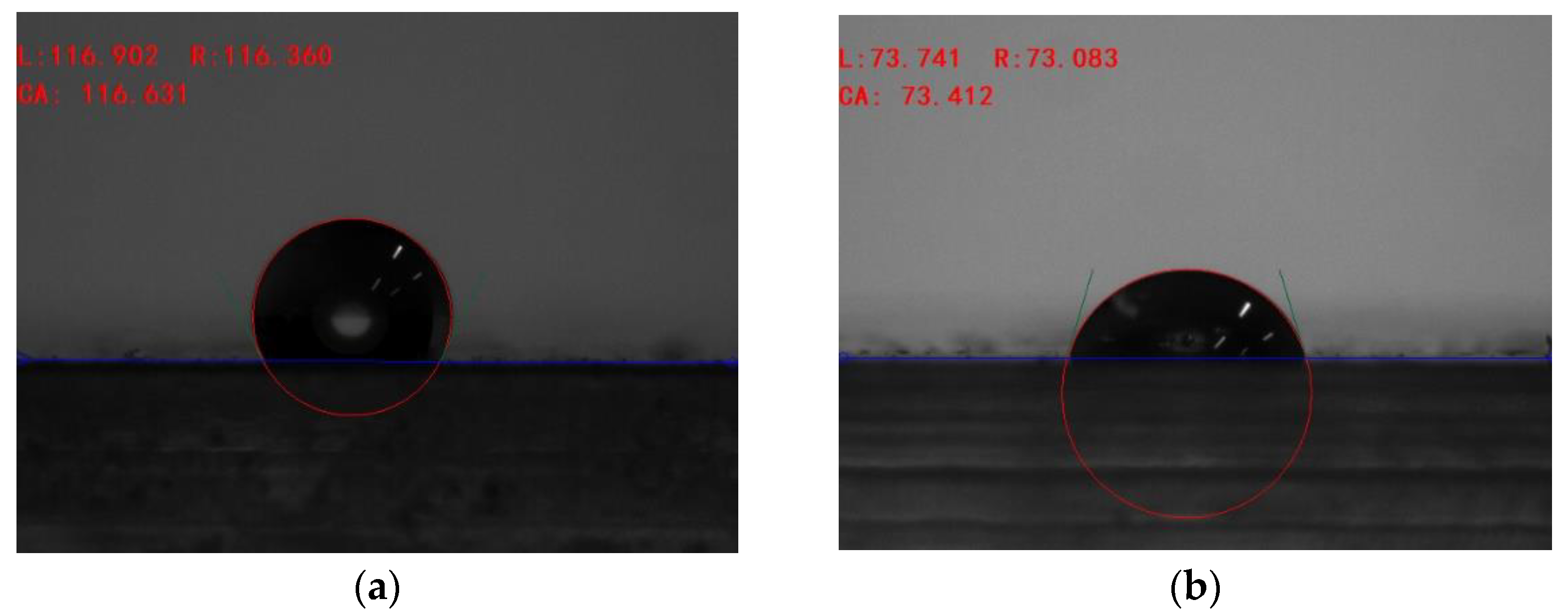
2.1. Material Preparation

The W/O emulsion is prepared with oil, water, and surfactant. The oil is mineral oil (3#, 5#) purchased from Huike Lubricant Company, Shenzhen, China. The water is deionized water, and the emulsifier is EYKOSI, which is a nanoparticle emulsifier manufactured by Changsarinen Commodity Co., Ltd. Changsha, China. The properties of the materials above are shown in Table 1. The specific preparation process is listed as follows. the oil, water and surfactant were firstly added into the centrifugal tube at a volume ratio of 90:7:3, slightly shaken manually in advance. Then, the centrifugal tube was placed in a mixer (VM-500S; JOANLAB, Huzhou, China) for 10 min, and the stable W/O emulsion could be formed under the shearing effect due to the high-speed rotation (3000 rpm).

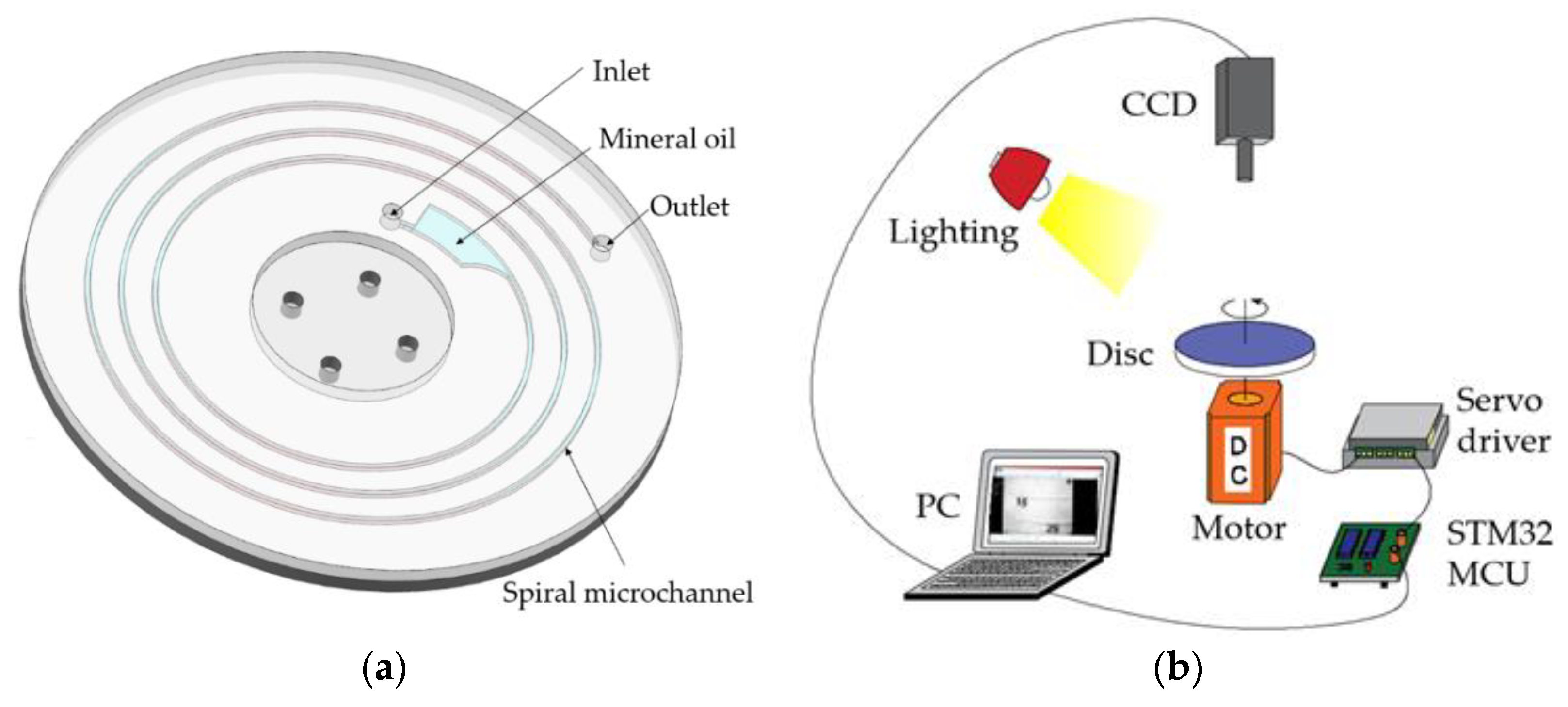
2.2. Experimental Setup

The structure of the disc is shown in Figure 1a. All structures of the disc (diameter = 130 mm) were designed using CAD software UG 8.5, including the inlet and outlet of the chip, spiral microchannels, and oil storage chamber. The specific manufacturing process of the chip is described as follows. Firstly, the microchannels and chamber were machined on the PMMA substrate with a thickness of 3 mm using a precision CNC milling machine. Then, the two processed PMMA plates were placed in the Ultrasonic Cleaning Machine (JT-1027HT; Jietuo, Shenzhen, China) and Plasma Cleaner (PDC-002; Harrick Plasma, Ithaca, NY, USA) for surface treatment, lasting for 10 min. Finally, the disposed PMMA plates were placed in the thermocompression bonder (WH-2000C; Wenhao, Suzhou, China) with the following working conditions. The pressure is set as 0.25 MPa, temperature is set as 100 °C, and the running time is 1 h. The microchannels of the chip were hydrophobically treated with CLEMENS (the surface interaction in the case of a hydrophobic PMMA surface with deionized water and mineral oil are shown in Appendix A). The simple centrifugal microfluidic chip with spiral microchannel was fabricated by the above method. And the parameters of the spiral microchannel are listed as follows. The spiral radius ranges from 35 mm to 55 mm. The change rate of the spiral radius is 0.637, 0.796 and 1.061 mm/rad, respectively. The cross-section is a rectangle with an aspect ratio of 1:1 and hydraulic diameter of 0.5 mm.
The whole centrifugal microfluidic system is shown in Figure 1b. Its running process is depicted as follows. The centrifugal microfluidic chip and a marking disk were connected to the motor coupling, which was driven by a brushless DC motor (80BL89S50-445TK0; Shidaichaoqun, Beijing, China). At the same time, the motor speed was controlled by servo driver (ZM-6615; Shidaichaoqun, Beijing, China) and STM32 MCU. The high-speed camera (FASTCAM Mini UX; Photron, Japan) and other imaging modules capture the flow state of the droplet in the rotary disc.
The specific experimental operation is described as follows. Prior to centrifugation, the mineral oil was filled into the oil storage chamber (about 0.5 mL) and spiral microchannel (about 0.21–0.35 mL) by a syringe. Then, the droplet with diameter of 200–300 μm selected by a metallographic microscope (15JF-V; CSOIF, Shanghai, China) was injected into the chip, and adjusted to mark 1 with a syringe. Finally, the motor could be started after the chip and the marking disc were fixed with the motor coupling. At the same time, a high-speed camera was used to record the flowing process of the droplet in the microchannel, and the camera parameters were set as: shooting speed 4000 fps, shutter speed 1/50,000 s. The images collected by the camera were analyzed by Photron-FASTCAM software to obtain the physical quantity of droplet flow. The obtained flow state of the droplet is shown in Figure 2. In the pictures, the time of flash photo group is the frame time corresponding to each photo at the shooting time, i.e., the time difference of droplet movement. Based on the marks on the pictures, the flow positions of the droplet in the microchannels at different times can be obtained, and the flow distance of the droplet can be calculated. We record the flowing distance of the droplet in 1 s and obtain the average velocity, which can be approximated as equal to the instantaneous velocity at the midpoint of the segment due to the short time and slow change of velocity. The specific processing of pictures is described in Appendix B.

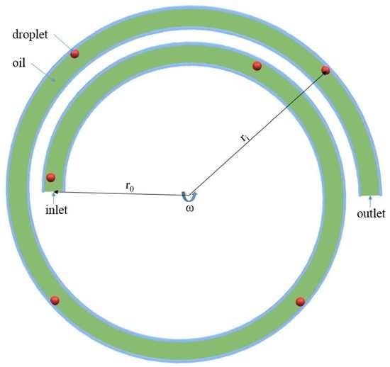
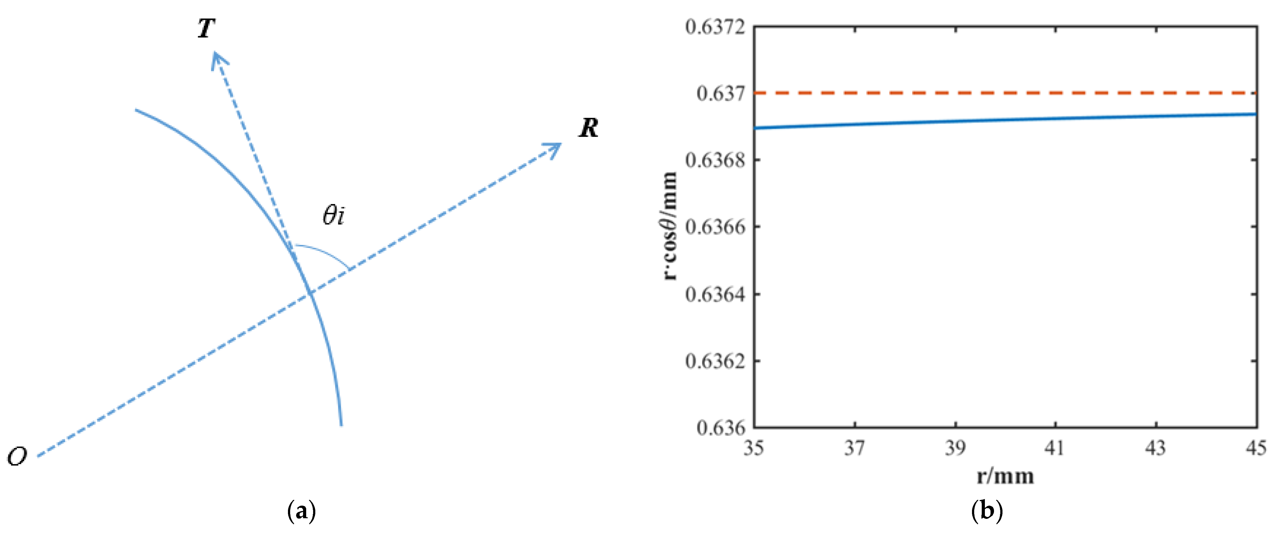
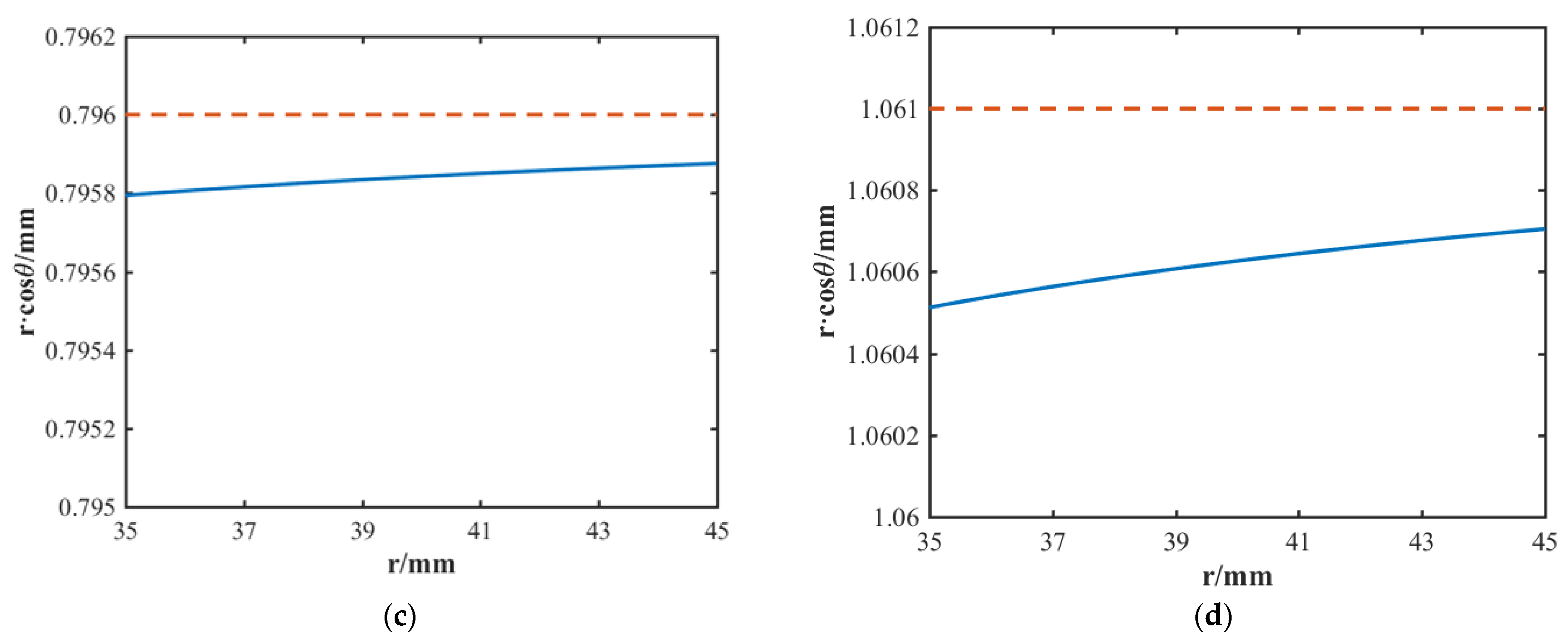
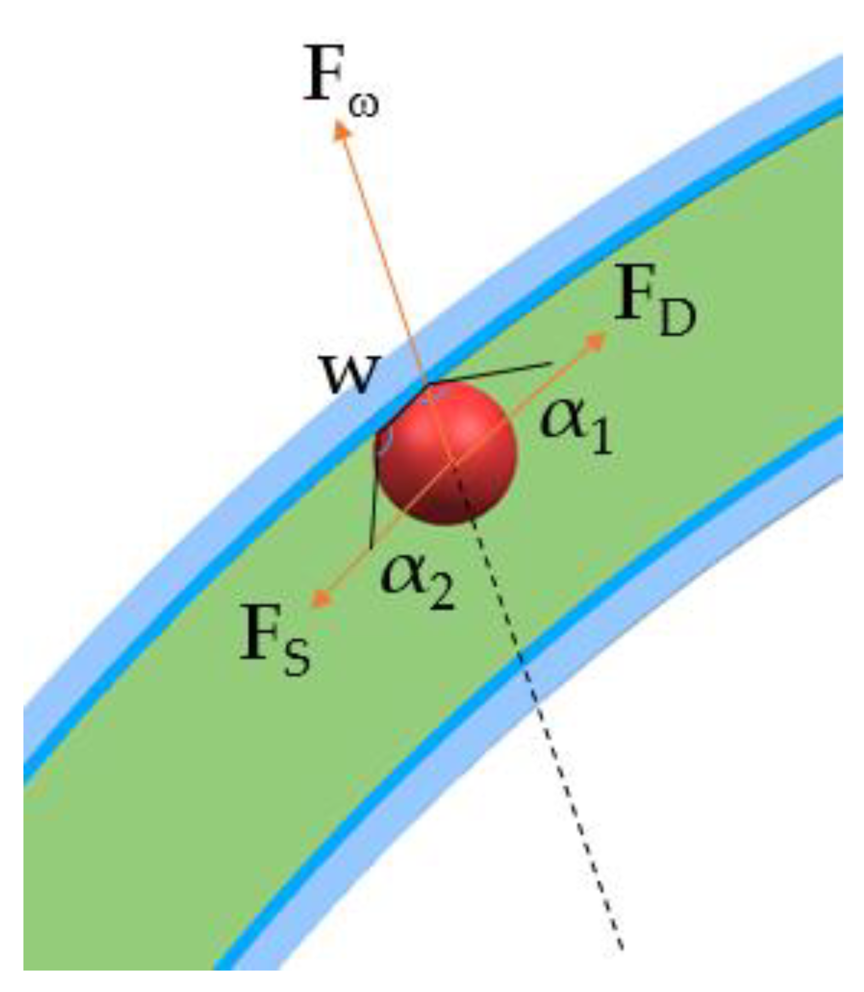
2.3. Working Principle

We perform the transport of the O/W droplet by applying a centrifugal force field perpendicularly to the axis of flow. Convection is induced by designing a structure with different distances between inlet and outlet from the center of rotation, resulting in a net hydrostatic pressure difference. Therefore, we designed a square-section microchannel structure with an Archimedes helix as the track line, and the polar coordinate expression of the helix as follows:
r = r 0 + a θ
where r0 is the initial spiral radius, a is the change rate of spiral radius, and θ is the polar angle in polar coordinates. In this case, the net hydrostatic pressure ΔP difference between inlet (r1) and outlet (r2) can be expressed as [19]:
Δ P = ρ o r ¯ Δ r ω 2
where r is the distance between the center of rotation and the mean radial point of the fluid inside the microchannel, Δr is the distance difference between the inlet and outlet relative to the center of rotation, ω is the rotational angular velocity, and ρo is the density of the oil phase. To study the motion of the oil phase, we consider quasi-equilibrium conditions, where ω is a constant, and ωv (v is the absolute velocity of the fluid) is so small that the influence of Euler force ( F E = ρ r d ω d t ) and Coriolis force ( F C = 2 ρ ω v ) can be ignored. At this point, the flow Q of oil phase in the microchannel can be given by net hydrostatic pressure difference ΔP and hydrodynamic resistance Rhd [20,21]:
Q = Δ P / R h d
The hydrodynamic resistance of the square microchannel can be approximately expressed as:
R h d = 8 ( 1 + A r ) 2 μ o l A r A 2
where Ar is the aspect ratio of the microchannel, A is the cross-sectional area, μo is the viscosity of oil, and l is the length of the microchannel. Assuming a parabolic flow profile in the continuous phase channel, and the cross-sectional area of all parts in the square microchannel as equal, the expression for the average velocity of the oil phase can be given by:
u o * = Q A = Δ P R h d A
Since the droplet is generally smaller than the microchannel hydraulic diameter in the present tests, the local fluid velocity at the droplet center can be expressed as:
u o = 3 2 u o * [ 1 ( d h D d h ) 2 ]
where D is the diameter of droplet and dh is the continuous phase hydraulic diameter. For a square microchannel, hydraulic diameter is equal to the microchannel diameter. The droplet movement in the oil phase is governed by the interplay of centrifugal force, drag force, and surface tension. The net resultant force of centrifugal and drag force should overcome the obstacles caused by unbalance of surface tension during the movement. The force analysis of droplet can be seen in Figure 3 (a detailed description of the model is shown in Appendix C).
We perform a simple theoretical estimate of those three forces acting on the droplet in the oil phase. With the action of the centrifugal field, the centrifugal force applied to the droplet in the rotating microchannel, Fω, is:
F ω = π 6 D 3 ρ w ω 2 r i
where ρw is the density of droplet, and ri is the distance of the droplet from the rotation center. At this time, the component value of the centrifugal force in the direction of velocity can be replaced by (a detailed derivation is shown in Appendix D):
F ω 1 = π 6 D 3 ρ w ω 2 a
The effect of drag force in the direction of velocity is positive and promotes droplet movement. When Reynolds number (Re) is small enough, the equation of drag force can be expressed as [22]:
F D = k π μ o ( u o u w ) D
where uw is the velocity of the droplet and k is the coefficient related to the viscosity, expressed as k = (3 + 2β)/(1 + β), and β is the viscosity ratio of the continuous phase and discrete phase, expressed as β = μow. With the movement of the droplet, the fluid molecules jump between adsorption sites due to the imbalance of surface tension, which impedes the droplet movement [23,24]. The resultant contact line resistance can be approximated as [25]:
F γ = γ w cos α 1 cos α 2
where γ is the oil-water interfacial tension, w is the width of the contact area, α1 is the advancing contact angle, and α2 is the receding contact angle. The resistance of the contact line can be calculated by measuring the geometrical parameters of the droplet in motion and substituting them into Equation (10).
The forces on the droplet are relatively stable with a steady speed of motor; we assume that the droplet is a rigid body for simplicity. Similar assumptions were also made by Roland [26] and NT Nguyen [26] et al. Its movement can be described as:
m d 2 x d t 2 + γ w cos α 1 cos α 2 π 6 D 3 ρ w ω 2 a k π μ o D ( u o d x d t ) = 0
where m is the mass of the droplet, x is a function of the droplet center position, dx/dt is the instantaneous absolute velocity of the droplet. For a small droplet, the inertial force can be ignored, when compared with other forces. Therefore, the kinematic behavior of the droplet is expected to be a first-order system [27], and we can take uw = dx/dt into Equation (11). Combining with the Equations (2)–(6) and (8)–(11), we can then obtain the droplet velocity, uw, as:
u w = λ 1 exp ( β t )
where λ = ω 2 a 192 k μ o [ ( 32 ρ w 9 k ρ o ) D 2 + 18 k ρ o d h D ] γ w cos α 1 cos α 2 k π D μ o , β = 6 k μ o ρ w D 2 . According to Equation (12), we can see that the quasi-static velocity of droplet movement is given by uws = (ω, a, D, μ, α, w).

3. Results and Discussion

It can be seen from Equation (12) that the movement of W/O droplet in the spiral microchannel driven by centrifugal field is related to the physical properties of materials, the rotation speed of the motor, and the change rate of the spiral radius. In the above model, we assumed that the droplet was a rigid body. In practice, the droplet will change such as stretching/shrinking with the action of various forces. So, the deformation of the droplet needs to be considered. In this paper, the aspect ratio is used to determine the degree of deformation of the droplet, which is defined as the ratio between the length in the direction of velocity and the width in the radial direction. The change in aspect ratio of the droplet under different conditions is shown in Figure 4. It can be seen that the change of the aspect ratio of the droplet mainly occurs in the acceleration stage of the motor. More than half of the increase occurs in the first 10 s after the motor starts to rotate. A relatively obvious jumping change occurs when the droplet is close to the wall, as a result of the radial deformation of the droplet being hindered by the wall. As the droplet moves outward along the spiral microchannel with a stable rotation speed, the aspect ratio increases steadily and slowly. At a large diameter of 0.3 mm, a high-speed of 1000 rpm and a low viscosity of 12.60 mPa⋅s, the deformation of droplet caused by the centrifugal force, viscous force, and interfacial stress is larger. The relationship of the three forces can be expressed with the Bond number (Bo = ρω2aD2) and the Capillary number (Ca = μu/γ). The interfacial tension of water-PMMA is 32 mN·m−1, the interfacial tension of water-oil is 41 mN·m−1. In the current case, the Bond number ranges from 6.46 × 10⁻³ to 2.51 × 10⁻² and the Capillary number ranges from 5.86 × 10⁻³ to 8.18 × 10⁻³. This shows that the surface tension force is dominant at the microscale. A smaller scale of the droplet has a stronger tension effect, and a larger viscosity has a stronger viscous stress, which can reduce the deformation of the droplet. When the motor stops gradually, the aspect ratio of the droplet decreases gradually and finally becomes smaller than the initial value, which indicates that the droplet is compressed. The slight compression of the droplet can be explained as an inertia effect. From the experimental results, the deformation amount of the droplet is far less than the initial size, and the minimum deformation of the droplet satisfies the rigid body assumption.
The flow state of the droplet at a steady rotation speed is essential. Thus, we intercept the flow state of the droplet within 10 to 90 s after the motor starts to rotate (Figure 4). In the condition of a = 1.061 mm/rad, ω = 1000 rpm, D = 0.3 mm, and μo = 12.60 mPa⋅s, the variation of the transient contact angles and the length ratio of the contact line with time at different measurement positions is shown in Figure 5. The contact angle (α1) of the leading-edge interface of the droplet gradually decreased with time, while the contact angle (α2) of the trailing-edge interface remained relatively constant (± 1°). The initial length of the contact line is 51 μm, which shows a relatively uniform increase with time. These values can then be used for kinematic analysis of the model. The observed velocity of the droplet in the microchannel is compared with the theoretical velocity, as shown in Figure 6. The instantaneous velocity here is defined as the ratio between the experimentally observed position and time. The fluctuation of data points can be explained as the influence of local defects in the processed microchannel, Coriolis force, and Euler force in the centrifugal field (which are ignored due to the slight influence) on the droplet’s motion, which eventually leads to the error of measured values (such as α1, α2, etc.). At this point, the SSE (the sum of squares due to error) is 0.037, which means that the error fluctuates little and can be allowed. It can be seen from Figure 6 that the actual measured velocity of the droplet has changed by 9.27% within 80 s, which is close to 11.23% of the theoretical value. The trend of the measured velocity is consistent with the theoretical velocity, and the velocity of the droplet increases slowly with the increase of the helical radius r (for every 1 mm, the velocity increases by about 0.042 mm/s, which is about 1.11% of the average velocity), which means the flow has a certain stability. The measured instantaneous velocity is slightly lower than the theoretical value, which is caused by flow errors due to the deformation. In this case, the absolute error at the minimum instantaneous velocity of the droplet is 0.34 mm/s and the absolute error at the maximum instantaneous velocity is 0.38 mm/s. The average absolute instantaneous error is about 0.37 mm/s and the error of the average velocity is about 9.81%, which is acceptable.
Model predictions were also experimentally verified over a range of speeds (600–1600 rpm). Here, the maximum change value of the aspect ratio of the droplet is 0.325, and the minimum is 0.005 (Figure 7). In this case, at a low rotation speed (less than 800 rpm), the change in the droplet’s maximum and minimum aspect ratio is small (less than 0.1), which indicates the deformation of the droplet in the movement process is small. At a low change rate of spiral radius of 0.673 mm/rad, the deformation degree of the droplet does not increase with the increase in the rotation speed. When the rotation speed is greater than 800 rpm, the deformation degree of the droplet increases exponentially with the change in the rotation speed. The larger the change rate of the spiral radius, the more severe the deformation degree. This is an expected result. An increase in the rotation speed and the change rate of the spiral radius corresponds to an increase in centrifugal driving force from Equation (8). Therefore, it is easier to overcome the deformation blocking effect caused by surface tension. However, at a low rotation speed, surface tension still dominates to block the deformation of the droplet, which has an influence on the prediction results of the model. At low rotation speeds (600 and 800 rpm), the average absolute error of instantaneous velocity is less than 5% of the average velocity (Figure 8). This shows better speed predictability, which corresponds to the small deformation in Figure 7. With an increase in rotation speed, the error between the prediction model and the reality increases. When the rotation speed is 1600 rpm, the average absolute error of instantaneous velocity reaches 1.34 mm/s, with the error in the same magnitude as the instantaneous velocity. At this point, the error is 16.52% of the average velocity, which shows that the error caused by deformation at a high rotation speed cannot be ignored. This shows that the proposed model can be used to predict the kinematics of W/O droplets in the spiral microchannel driven by centrifugal field over a range of applied rotation speeds. It is worth mentioning that for the combination of the spiral microchannel and centrifugal driving, we found that a larger velocity regulation range can be obtained by adjusting the rotation speed. When the rotation speed is 600 rpm, the average velocity is 1.67 mm/s. When the rotation speed reaches 1600 rpm, the average velocity is about 8.11 mm/s, which is nearly five times that of the low rotation speed. The greater velocity is very helpful for the transportation of the droplet.

4. Conclusions

This paper presents a method of transporting the W/O droplet by centrifugal driving combined with a spiral microchannel. Based on the rigid body hypothesis, the kinematic model of W/O droplets is established. The changes in centrifugal force, viscous force, and surface tension are considered, leading to the droplet deformation influence on the velocity in the flow process. Comparing the theoretical value with the experimentally measured value, it is found that the theoretical value is slightly larger than the measured value due to the deformation of the droplet. Still, the law of the two values is consistent, and the error between them is less than 16.52% within 1600 rpm, which shows that the model presents good predictability. At the same time, we find that in the condition of a = 1.061 mm/rad, every time the spiral radius r increases by 1 mm, the speed increases by about 0.042 mm/s, which is about 1.11% of the average velocity. This means that the W/O droplet driving mode is stable in flow. It can achieve a great range of velocities by changing the rotation speed without using precision instruments and expensive equipment. The average velocity at 1600 rpm is 8.11 mm/s, which is nearly five times that of the average velocity (1.67 mm/s) at 600 rpm. The driving concept described in this paper can be applied in the transportation and classification of droplet-based microfluidics, providing a reference and basis for the flow research of droplets driven by a centrifugal field.

Author Contributions

Conceptualization, Z.X. (Zhongqiang Xie); methodology, Z.X. (Zhongqiang Xie); software, Z.X. (Zhongqiang Xie); validation, Y.C., J.W. and Z.X. (Zhaokun Xian); formal analysis, Z.X. (Zhongqiang Xie); investigation, Z.X. (Zhongqiang Xie) and H.Y.; resources, H.Y.; data curation, Z.X. (Zhongqiang Xie), Y.C., J.W. and Z.X. (Zhaokun Xian); writing—original draft preparation, Z.X. (Zhongqiang Xie); writing—review and editing, Z.X. (Zhongqiang Xie) and H.Y.; visualization, Z.X. (Zhongqiang Xie); supervision, H.Y.; project administration, H.Y.; funding acquisition, H.Y. All authors have read and agreed to the published version of the manuscript.

Funding

This research was funded by the Guangxi Bagui Scholars Project (No. C3010099204).

Institutional Review Board Statement

Not applicable.

Informed Consent Statement

Not applicable.

Data Availability Statement

Not applicable.

Acknowledgments

We would like to thank the financial support from the Guangxi Bagui Scholars Project (Grant No. C3010099204). The first author also wants to thank his girlfriend, Yy Ying, for her care.

Conflicts of Interest

The authors declare no conflict of interest.

Appendix A

Figure A1 shows the surface interaction (contact angle, with values) in the case of a hydrophobic PMMA surface with deionized water (a) and hydrophobic PMMA surface with mineral oil (b). The contact angles of deionized water and mineral oil are measured by Contact Angle Meter (SDC-200S; SINDIN, Dongguan, China).
Figure A1. (a) The surface interaction in the case of a hydrophobic PMMA surface with deionized water; (b) the surface interaction in the case of a hydrophobic PMMA surface with mineral oil.
Applsci 12 04362 g0a1

Appendix B

We used the MATLAB software to analyze the bitmap image of droplet flow. The original image is shown in Figure A2a. The specific processing of the image is described as follows. Firstly, the grayscale threshold of the image was found using the Otsu method. Then, the image was subjected to double-layer filtering (noise reduction) based on a coif2 wavelet. Finally, the curve from the region of interest in the image was identified and extracted to reconstruct the shape of the interface (Figure A2b). The contact angle of the droplet is obtained by curve fitting at the contact point interface (Figure A2b), and measured in ImageView software. A similar method was also used by Schertzer et al. [28]. The contact line (obtained by extracting the curve between the contact points in Figure A2b and the aspect ratio are measured by comparing pixel points using ImageJ software.
Figure A2. (a) Original image of droplet flow; (b) the droplet image processed by MATLAB software.
Applsci 12 04362 g0a2

Appendix C

Due to the limitations of the equipment, we cannot directly observe whether there is a thin oil film between the channel wall and the droplet (even if there is, it is very tiny and difficult to observe). Therefore, in the early stage of the experiment, we use the ink-in-oil (blue) experiment and the simulation by COMSOL software to verify the correctness of the model. The experimental results are shown in Figure A3 and Figure A4, respectively.
Instead of directly observing the presence of a thin oil film, we observed the wall residue after the ink-in-oil experiment. And in order to avoid the accident of the experiment, the wall surface was observed 15 times in the ink-in-oil driving experiment, 3 times in total. We found that there was ink (blue) residue on the wall surface of the flowing channel (Figure A3), which means that the droplet was in contact with the wall. If there is a thin oil film between the channel wall and the droplet, this phenomenon may not exist.
Figure A3. The experiment of ink-in-oil at 1200 rpm. There was ink (blue) residue on the wall surface of the flowing channel.
Applsci 12 04362 g0a3
At the same time, we used COMSOL software to simulate the process of the centrifugal driving of the water-in-oil droplet in the microchannel. The simulation results of the intercepted symmetry plane are shown in Figure A4. As we can clearly see from Figure A4, the droplet finally touches the wall and flows downstream under the action of the centrifugal force. Therefore, we think that there is no thin oil film between the channel wall and the droplet, and, finally, boldly adopted the model in this paper.
Figure A4. The COMSOL simulation of the centrifugal driving of W/O droplet.
Applsci 12 04362 g0a4

Appendix D

Combining with Equation (7) and Figure A5a, we can obtain the component of centrifugal force in the direction of velocity as follows:
F ω 1 = π 6 D 3 ρ w ω 2 r i cos θ i  
where θi is the angle between the radial direction and the velocity direction of the droplet at any position in the spiral microchannel. With the constant external conditions, the component of centrifugal force is mainly related to ri and θi. The values of ri and θi in different positions are variable, which makes the calculation complicated. Therefore, with the help of MATLAB software, we have written scripts to calculate the relationship between ri and the change rate of the spiral radius a of 0.637 mm/rad, 0.796 mm/rad and 1.061 mm/rad. The results are shown in Figure A5b–d, respectively. As we can see from Figure A4, ri⋅cosθi increases with the increase in ri, which means that the flow directional component of centrifugal force gradually increases as the droplet flows downstream. Within the range of ri from 35 to 45 mm, the values of ri changed by 0.5 × 10⁻⁴ mm (a = 0.637 mm/rad), 0.9 × 10⁻⁴ mm (a = 0.796 mm/rad), and 1.9 × 10⁻⁴ mm (a = 0.796 mm/rad), respectively. This indicates that the larger the value of a, the greater the centrifugal force component and the greater the force increment. At this point, the change rates of ri⋅cosθi relative to a in numerical value are from 0.008% to 0.014% (a = 0.637 mm/rad), from 0.026% to 0.015% (a = 0.796 mm/radian), and from 0.046% to 0.028% (a = 1.061 mm/radian), respectively, which is far less than 1%. It shows that when a is determined, although the flow directional component of the centrifugal force increases with the increase in ri, the change in increment of force is not obvious. In addition, ri⋅cosθi is close to a in value. Therefore, the component of centrifugal force in the direction of velocity can be numerically replaced by Equation (8). It is worth mentioning that Equation (8) is also applicable to other values of a (a < 4 mm/rad), although we will not provide further proof here.
Figure A5. (a) The angle between the radial direction (R) and the direction of velocity (T) at any position in the spiral microchannel; (bd) the relationship between r and rcosθ for the change rate of the spiral radius of 0.637 (b), 0.796 (c), and 1.061 (d) mm/rad.
Applsci 12 04362 g0a5aApplsci 12 04362 g0a5b

References

  1. Nazir, A.; Vladisavljević, G.T. Droplet breakup mechanisms in premix membrane emulsification and microfluidic channels. Adv. Colloid Interface Sci. 2021, 290, 102393. [Google Scholar] [CrossRef]
  2. Liu, Z.M.; Yang, Y.; Du, Y.; Pang, Y. Advances in Droplet-Based Microfluidic Technology and Its Applications. Chin. J. Anal. Chem. 2017, 45, 282–296. [Google Scholar] [CrossRef]
  3. Chen, J.S.; Jiang, J.H. Droplet Microfluidic Technology: Mirodroplets Formation and Manipulation. Chin. J. Anal. Chem. 2012, 40, 1293–1300. [Google Scholar] [CrossRef]
  4. Ringkai, H.; Tamrin, K.F.; Sheikh, N.A.; Mohamaddan, S.; Ruberto, C.D. Evolution of Water-in-Oil Droplets in T-Junction Microchannel by Micro-PIV. Appl. Sci.-Basel 2021, 11, 5289. [Google Scholar] [CrossRef]
  5. Lee, T.Y.; Choi, T.M.; Shim, T.S.; Frijns, R.; Kim, S.H. Microfluidic production of multiple emulsions and functional microcapsules. Lab Chip 2016, 16, 3415–3440. [Google Scholar] [CrossRef] [PubMed]
  6. Ito, M.; Sugiura, H.; Ayukawa, S.; Kiga, D.; Takinoue, M. A Bacterial Continuous Culture System Based on a Microfluidic Droplet Open Reactor. Anal. Sci. 2016, 32, 61–66. [Google Scholar] [CrossRef] [PubMed] [Green Version]
  7. Cunha, A.G.; Mougel, J.B.; Cathala, B.; Berglund, L.A.; Capron, I. Preparation of Double Pickering Emulsions Stabilized by Chemically Tailored Nanocelluloses. Langmuir 2014, 30, 9327–9335. [Google Scholar] [CrossRef]
  8. Wu, Z.H.; Gong, Z.Y.; Ao, Z.; Xu, J.H.; Cai, H.W.; Muhsem, M.; Heaps, S.; Bondesson, M.; Guo, S.S.; Guo, F. Rapid Microfluidic Formation of Uniform Patient-Derived Breast Tumor Spheroids. ACS Appl. Bio Mater 2020, 3, 6273–6283. [Google Scholar] [CrossRef] [PubMed]
  9. Mou, L.; Hong, H.; Xu, X.J.; Xia, Y.; Jiang, X.Y. Digital Hybridization Human Papillomavirus Assay with Attomolar Sensitivity without Amplification. ACS Nano 2021, 15, 13077–13084. [Google Scholar] [CrossRef] [PubMed]
  10. Watanabe, H.; Kawano, R. Channel Current Analysis for Pore-forming Properties of an Antimicrobial Peptide, Magainin 1. Using the Droplet Contact Method. Anal. Sci. 2016, 32, 57–60. [Google Scholar] [CrossRef] [PubMed] [Green Version]
  11. Michael, I.; Kim, T.H.; Sunkara, V.; Cho, Y.K. Challenges and Opportunities of Centrifugal Microfluidics for Extreme Point-of-Care Testing. Micromachines 2016, 7, 32. [Google Scholar] [CrossRef] [PubMed] [Green Version]
  12. Cheng, J.T.; Chen, C. L. Active thermal management of on-chip hot spots using EWOD-driven droplet microfluidics. Exp. Fluids 2010, 49, 1349–1357. [Google Scholar] [CrossRef]
  13. An, S.; Zhu, M.Y.; Gu, K.; Jiang, M.D.; Shen, Q.C.; Fu, B.W.; Song, C.Y.; Tao, P.; Deng, T.; Shang, W. Light-Driven Motion of Water Droplets with Directional Control on Nanostructured Surfaces. Nanoscale 2020, 12, 4295–4301. [Google Scholar] [CrossRef] [PubMed]
  14. Ding, Y.; Howes, P.D.; Demello, A.J. Recent Advances in Droplet Microfluidics. Anal. Chem. 2019, 92, 132–149. [Google Scholar] [CrossRef] [PubMed]
  15. Zhang, K.; Liang, Q.L.; Ma, S.; Mu, X.; Hu, P.; Wang, Y.M.; Luo, G.A. On-chip manipulation of continuous picoliter-volume superparamagnetic droplets using a magnetic force. Lab Chip 2009, 9, 2992–2999. [Google Scholar] [CrossRef] [PubMed]
  16. Liu, M.; Sun, X.T.; Yang, C.G.; Xu, Z.R. On-chip preparation of calcium alginate particles based on droplet templates formed by using a centrifugal microfluidic technique. J. Colloid Interface Sci. 2016, 466, 20–27. [Google Scholar] [CrossRef]
  17. Wang, Y.Y.; Liu, S.Y.; Zhang, T.K.; Cong, H.J.; Wei, Y.Y.; Xu, J.B.; Ho, Y.P.; Kong, S.K.; Ho, H.P. A centrifugal microfluidic pressure regulator scheme for continuous concentration control in droplet-based microreactors. Lab Chip 2019, 19, 3870–3879. [Google Scholar] [CrossRef] [PubMed]
  18. Bouchard, A.P.; Duford, D.A.; Salin, E.D. Non-contact Addition, Metering, and Distribution of Liquids into Centrifugal Microfluidic Devices in Motion. Anal. Sci. 2010, 82, 8386–8389. [Google Scholar] [CrossRef]
  19. Arosio, P.; Müller, T.; Mahadevan, L.; Knowles, T.P.J. Density-Gradient-Free Microfluidic Centrifugation for Analytical and Preparative Separation of Nanoparticles. Nano Lett. 2014, 14, 2365–2371. [Google Scholar] [CrossRef] [PubMed]
  20. Burger, R.; Kinahan, D.J.; Cayron, H.; Reis, N.; Fonseca, J.; Ducree, J. Siphon-Induced Droplet Break-Off for Enhanced Mixing on a Centrifugal Platform. Inventions 2019, 5, 1. [Google Scholar] [CrossRef] [Green Version]
  21. Ducrée, J.; Haeberle, S.; Lutz, S.; Pausch, S.; Stetten, F.V.; Zengerle, R. The centrifugal microfluidic Bio-Disk platform. J. Micromech. Microeng. 2007, 17, S103–S115. [Google Scholar] [CrossRef]
  22. Husny, J.; Cooper-White, J.J. The effect of elasticity on drop creation in T-shaped microchannels. J. Non-Newton. Fluid Mech. 2006, 137, 121–136. [Google Scholar] [CrossRef]
  23. Blake, T.D.; Clarke, A.; De Coninck, J.; de Ruijter, M.J. Contact Angle Relaxation during Droplet Spreading: Comparison between Molecular Kinetic Theory and Molecular Dynamics. Langmuir 1997, 13, 2164–2166. [Google Scholar] [CrossRef]
  24. Blake, T.D.; Haynes, J.M. Kinetics of liquid/liquid displacement. Colloid Interface Sci. 1969, 30, 421–423. [Google Scholar] [CrossRef]
  25. Kim, H.Y.; Lee, H.J.; Kang, B.H. Sliding of Liquid Drops Down an Inclined Solid Surface. Colloid Interface Sci. 2002, 247, 372–380. [Google Scholar] [CrossRef] [Green Version]
  26. Baviere, R.; Boutet, J.; Fouillet, Y. Dynamics of droplet transport induced by electrowetting actuation. Microfluid. Nanofluid. 2008, 4, 287–294. [Google Scholar] [CrossRef]
  27. Nguyen, N.T.; Beyzavi, A.; Ng, K.M.; Huang, X.Y. Kinematics and deformation of ferrofluid droplets under magnetic actuation. Microfluid. Nanofluid. 2007, 3, 571–579. [Google Scholar] [CrossRef]
  28. Schertzer, M.J.; Gubarenko, S.I.; Ben-Mrad, R.; Sullivan, P.E. An empirically validated analytical model of droplet dynamics in electrowetting on dielectric devices. Langmuir 2010, 26, 19230–19238. [Google Scholar] [CrossRef]
Figure 1. (a) The structure of the chip; (b) the components and instrumental configuration used for the experiments.
Applsci 12 04362 g001
Figure 2. The motion state of the W/O droplets in microchannels captured by high-speed photography.
Applsci 12 04362 g002
Figure 3. The force analysis of droplet movement.
Applsci 12 04362 g003
Figure 4. The experimentally observed change in the aspect ratio of the droplet for different conditions (a = 1.061 mm/rad).
Applsci 12 04362 g004
Figure 5. The experimentally observed change in the transient contact angles (α1, α2) and the length ratio of the contact line (a = 1.061 mm/rad, n = 1000 rpm, D = 0.3 mm, μo = 12.60 mPa⋅s).
Applsci 12 04362 g005
Figure 6. The measured velocity and the theoretical velocity of the droplet at different locations (a = 1.061 rad/mm, n = 1000 rpm, D = 0.3 mm, μo = 12.60 mPa⋅s).
Applsci 12 04362 g006
Figure 7. The maximum (closed) and minimum (open) aspect ratios of the droplet as a function of the rotating speed for the change rate of spiral radius of 0.637 (square), 0.796 (triangle), and 1.061 (diamond) mm/rad (D = 0.3 mm, μo = 12.60 mPa⋅s).
Applsci 12 04362 g007
Figure 8. The average velocity and the average absolute error of instantaneous velocity as a function of the rotation speed (D = 0.3 mm, μo = 12.60 mPa⋅s, a = 1.061 mm/rad).
Applsci 12 04362 g008
Table 1. Physical properties of materials.
MaterialDensity/g·mLViscosity/mPa·sSurface Tension/mN·m−1
DI water1172.0
3# Oil0.82712.6025.9
5# Oil0.82018.1130.3
Publisher’s Note: MDPI stays neutral with regard to jurisdictional claims in published maps and institutional affiliations.

