Article

Improved U-Net++ with Patch Split for Micro-Defect Inspection in Silk Screen Printing

1
Department of Smart Factory Convergence, Sungkyunkwan University, 2066 Seobu-ro, Jangan-gu, Suwon 16419, Korea
2
AI Reserach, iShango Corporate, 5, Gasan Digital 1-ro, Geumcheon-gu, Seoul 08594, Korea
*
Author to whom correspondence should be addressed.
Appl. Sci. 2022, 12(9), 4679; https://doi.org/10.3390/app12094679
Submission received: 20 March 2022 / Revised: 3 May 2022 / Accepted: 4 May 2022 / Published: 6 May 2022
(This article belongs to the Special Issue Applications of Deep Learning and Artificial Intelligence Methods)

Abstract

:
The trend of multi-variety production is leading to a change in the product type of silk screen prints produced at short intervals. The types and locations of defects that usually occur in silk screen prints may vary greatly and thus, it is difficult for operators to conduct quality inspections for minuscule defects. In this paper, an improved U-Net++ is proposed based on patch splits for automated quality inspection of small or tiny defects, hereinafter referred to as ‘fine’ defects. The novelty of the method is that, to better handle defects within an image, patch level inputs are considered instead of using the original image as input. In the existing technique with the original image as input, artificial intelligence (AI) learning is not utilized efficiently, whereas our proposed method learns stably, and the Dice score was 0.728, which is approximately 10% higher than the existing method. The proposed model was applied to an actual silk screen printing process. All of the fine defects in products, such as silk screen prints, could be detected regardless of the product size. In addition, it was shown that quality inspection using the patch-split method-based AI is possible even in situations where there are few prior defective data.

1. Introduction

To strengthen the competitiveness of manufacturing companies in response to diverse consumer demands, many manufacturing companies are turning to multi-product production [1,2]. In the silk screen printing industry, the types of products can change in a short period of time, and product quality inspection is also evolving from manual inspection by workers or using existing machine vision inspection algorithms to using deep learning-based methods [3,4,5]. When visual inspection is carried out by the operator, the type of defect also changes whenever the variety of the material is changed, making it difficult to inspect fine defects, which can lead to market leakage of defective products.
Recently, various services have been developed using deep learning technology for numerous computer vision tasks. Deep learning techniques are often applied for automatic quality inspection because quality control in the manufacturing industry involves many repetitive tasks by workers. To this end, MVTec has released the MVTec anomaly detection (AD) dataset and many studies on vision quality inspection are conducted using this dataset [6].
Silk screen printing is a printing method in which a hole is made using light and ink is then applied through the hole. Quality inspection of silk screen-printed products requires workers with several years of experience in conducting quality inspections. However, even skilled workers cannot avoid eye fatigue and human error, thus, being unable to carry out the work for more than a certain period. Quality standards are judged qualitatively rather than quantitatively [7]. In such a situation, bad market outflow occurs and production has difficulty responding to this, whereby the competitiveness of the company in the market is inevitably reduced. In such a situation, bad market outflow occurs and production has difficulty responding to this, whereby the competitiveness of the company in the market is inevitably reduced. For these silk-screen printing companies, quality inspection automation, that is, a deep learning-based vision system, is necessary. Silk print defect detection requires very small defects to be detected while inspecting various products at the same time. There are many different types of defects and there are cases in which one must shine light from a specific angle to see it. Therefore, it is necessary to verify the lighting to accurately identify each defect. In addition, in the case of silk prints, the size of the product is diverse and the size of the defect is very small compared to the size; therefore, it is necessary to study this process in detail.
In this study, the aim was to determine whether small defects could be detected in one product. A classification method, such as patch distribution modeling (PaDiM), shows high performance in anomaly detection, even when trained on a small dataset [8]. One-class classification, such as using PaDiM, judges abnormality with respect to what is defined as normal, so establishing the normality is important [9,10]. However, it is difficult to define the normal data acquired for each shooting point. In addition, because of multi-variety characteristics, it is impossible to define normality. Therefore, in this study, segmentation was performed using general supervised learning [11,12]. As mentioned earlier, the size of silk print defects is very small compared to the product size. To solve this problem, patch sampling was considered without losing the information in the image. Additionally, a learning and inference technique was applied. Patch sampling is a method that is used when the original image cannot be input into the graphics processing unit (GPU) memory [13]. The convolutional neural network (CNN) model has problems such as unnecessary redundancy of overlapping patches, and a tradeoff between localization accuracy and use of context is required [14,15]. However, U-Net is capable of precise analysis because of its increased upscaling ability inherent in its symmetric architecture with skip-connection [16]. Furthermore, U-Net++ does not treat skip-connection as a simple add operation but adds a layer to the connection to further improve the upscaling ability, enabling more precise analysis. In addition, in the manufacturing industry where the cycle time is very important, quality inspection must be carried out efficiently. By enabling model pruning, inferences can be implemented not only at high speed but also with high performance [17].
The patch-split method solves the difficult problem of detecting the defects when the size of the defect is small compared to the size of the product. With this processing method, defects in the image can be accurately identified by using the patch level as input rather than the original image. Most computer vision tasks perform transfer learning using the ImageNet pretrained model; however, the ImageNet pretraining is mostly performed on a size of 224 or 384. However, computer vision tasks used in actual industrial sites often have a resolution of 1000 pixels or higher [18]. Thus, it is necessary to overcome the large differences in image resolution between the images learned during pretraining and the data generated from the real problem. The task is to detect a small object, which is difficult, and a lot of information is lost in resizing the image to 224 or 384. To overcome the difference in resolution, a pretrained model must be created to learn anew from large-size image data generated in the real world, but this requires considerable time and resources. However, our study was characterized by the efficient solving of patch splits that could be broadly divided into learning and inference. First, during learning, augmentation was required to solve the problems of imbalance and insufficient data. Therefore, a random crop was applied rather than splitting the original image. Thus, images with many defects could be created using one original image. The learning was performed using the patch level accordingly obtained as input. In the next step, training was conducted using U-Net++, which can implement inference at high speeds and enables precise analysis. A robust model is required to avoid false inspections when the learned model is applied to the field because of insufficient data from the manufacturing company [19]. To this end, instead of learning with a single loss function, several loss functions were combined, suitable for segmentation, to proceed with learning. When performing inference, duplicate inspection harms the production cycle time; therefore, the original image was divided by patch size, as previously studied. This divided patch-level image was input into the U-Net++ model that was trained to find defects in the product. Furthermore, a quality inspection process was proposed for microdefects. In addition, a self-manufactured hardware capable of inspecting products of various sizes, an image acquisition method that could find microdefects using the corresponding mechanical part, and a method of finding and processing microdefects in an easy-to-understand manner, were studied [20].
This paper proposes an improved U-Net++ based on the patch-split method to effectively detect defects. The paper makes the following contributions:
  • A learning and inference method based on the patch-split method is proposed to detect defects that are minute compared to the product size.
  • A combination of several loss functions is proposed to solve the problem of robustness during inference resulting from a lack of data in the manufacturing industry.
  • A microdefect inspection process is proposed for quality inspection in a manufacturing environment with various product sizes.
The remainder of this paper is organized as follows. Section 2 provides an overview on U-Net and U-Net++, silk screen-printing, defects, and patch sampling. In Section 3, the proposed architecture is described in detail. In Section 4, the experimental environment, dataset, evaluation index, and results are described. Finally, in Section 5, the conclusions of our study are presented and future research is suggested.

2. Related Work

2.1. U-Net and U-Net++

U-Net is an end-to-end, fully convolution-based model proposed for segmentation. The sliding window method used in existing CNNs has two disadvantages. The first is the unnecessary redundancy of overlapping patches and the second is the tradeoff between localization accuracy and context use. U-Net is divided into a contraction path, which is the left part where the size of the activation map decreases based on the center, and an expansion path, which is the right part where the size of the activation map increases, as shown in Figure 1. There are many similarities to a convolutional autoencoder (CAE) [21,22]. CAE is used in various fields such as generator models, denoising, super-resolution, and self-supervised learning, by encoding a small feature map through a convolution layer and then returning to the original size using a deconvolution layer [23]. However, the utility of CAE is limited because of the performance limitations of the decoder in upscaling. However, in U-Net, this limitation allows the capturing of context of the CNN image in the contraction path and the expansion path upsamples the reduced feature map to increase it to a size similar to the original image, whereby a segmentation map with accurate location information can be obtained [24]. The symmetric architecture with skip-connection allows precision analysis with increased upscaling ability, as applied in the biomedical field.
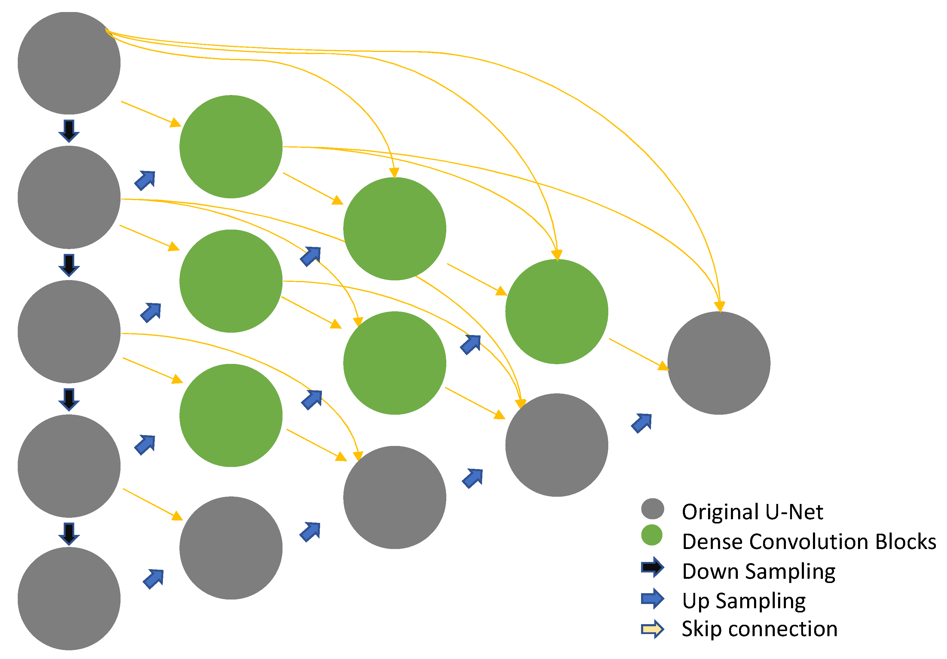
As shown in Figure 2, U-Net++ differs from U-Net in two major ways. The first is the redesigned skip pathways. Although the original U-Net has skip-connection, U-Net++ borrows the idea of DenseNet and connects the semantic gap between the encoder and decoder. The second method is deep supervision. This method averages the output of each branch and uses it as a result. U-Net++ does not use the skip-connection as a simple add operation as in U-Net, but adds a layer to the connection to further improve the upscaling ability, enabling precise analysis. Inference can be implemented at high speed. In particular, the convolution layer, which is the first layer of the ImageNet pretraining model, requires color information for data treated in three channels.

2.2. Silk Screen Printing Defect

Silk screen printing is a widely used printing technique. As shown in Figure 3, a hole is made using light and ink is then applied through the hole. In the early days, the pongee cloth was used, but with development of the industry, the pongee cloth became obsolete, and chemical products such as nylon, Teflon, and metal stainless steel mesh are mostly used instead. This is an inexpensive process and dark-colored objects can be used for printing [25].
Silk screen printing defects can occur during printing as well as drying, and some defects materialize after some time had elapsed. Defects in the printing process include plate clogging, which refers to the screen being clogged during printing, and other defects such as line marks or stains in the printing direction, spreading of the printing surface, and static ink splashing on caustics. Defects in the drying process include boiling a hole, such as foam, due to evaporation of the solvent during drying; whitening of the coating; pinhole, or the presence of a needle-like hole in the coating when drying ink; and creasing of a lower coating. Defects after elapsed time include mold and discoloration of the coating surface due to high-temperature and humidity, cracks in the coating film with aging, and peeling of the ink coating film from the printed material [26].
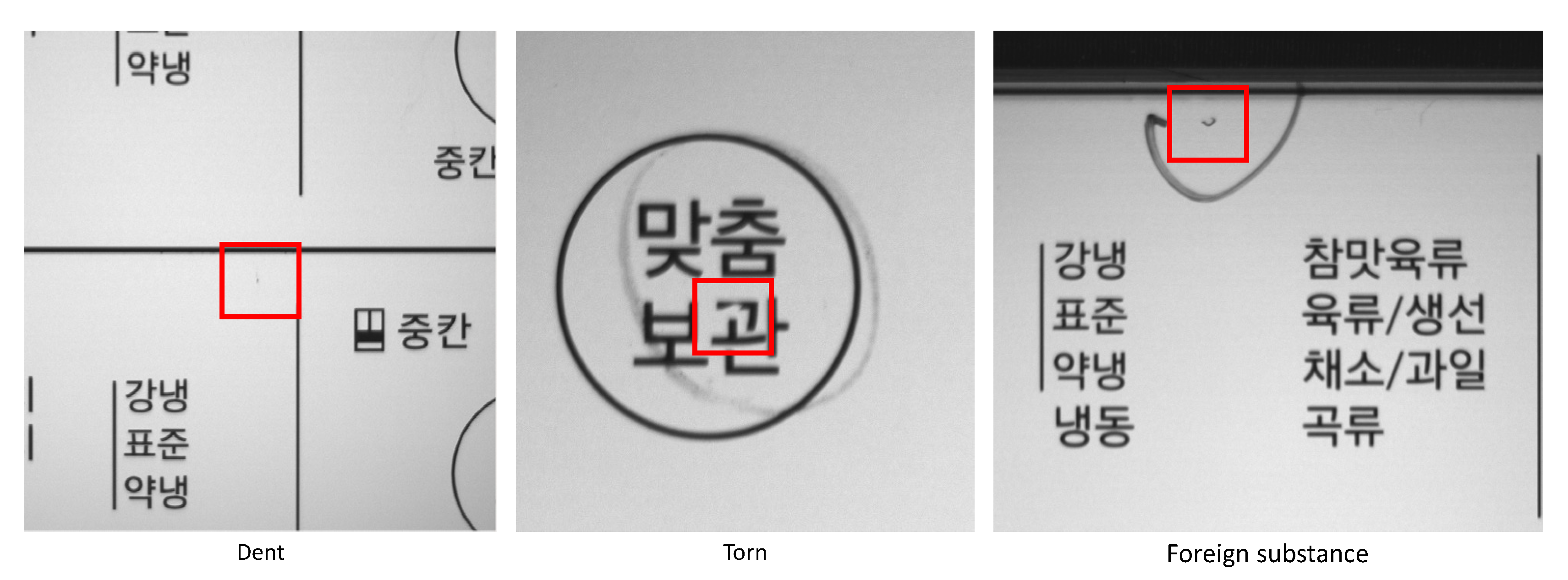
The types of defects in silk screen printing that occur during the manufacturing process are very diverse, as shown in Figure 4. Black spots and stains are the black ink on the surface of the printed matter. Light leakage is a defect in which light passes behind an unmasked part of the LED display area. Even if the defect is very small, it can easily be noticed by the user. A scratch is longitudinally centered and protruding edges appear on the upper surface around the handling part. A The dent is pressed by a sharp object on the upper surface around the handling part, so that the center plunges and the edges protrude. Bleeding is a phenomenon in which a print is unclear and blurred. Torn is a phenomenon in which characters or designs are not clearly printed or removed. Dust refers to contamination by foreign substances during printing or stamping.

2.3. Patch Sampling

Patch sampling is a method used when the original image cannot be placed in the GPU memory at once. For input into the GPU, a set of patch levels is selected rather than an image level. There are three major selection methods for patch sampling, as illustrated in Figure 5. The first is random selection. This is the simplest method that samples a patch at the image level. During each training epoch, a random patch is selected from each image and the training proceeds. The number and size of the patch must be sufficiently small to fit the GPU memory. The second is random selection after the desired object is detected. This is a method of randomly selecting a patch after locating the main analysis target. The third method is cluster-image patching. This is a way to view an object from a more diverse perspective. This is achieved by individually clustering the patches in each image [27].

3. Improved U-Net++ with Patch-Split Method

In this section, the overall architecture of the proposed concept is introduced along with an improved segmentation technique utilizing patch split to detect very small defects compared to the product size. In addition, a microdefect inspection process for silk screen prints is proposed.

3.1. System Architecture

The proposed improved segmentation technique divides the original image into patch units and analyzes the patches to detect minute defects in silk screen prints, whereby an image that has undergone patch splitting is used as input data rather than the original image. In addition, the design addresses the data imbalance problem in the manufacturing industry that leads to very poor image quality and bad products. To address the imbalance issue, the proposed architecture, shown in Figure 6, increases the defective area compared to the entire input image while maintaining a resolution approaching the input size of most CNNs. The convolution layer, which is the first layer of the ImageNet pretraining model, requires color information for data treated in three channels, but the data for the task are grayscale data and the convolution layer of the first layer consists of one channel. The ImageNet pretrained model is used for encoder weights in the U-Net + + structure, and the input layer and decoder parts are learned using weights generated by random values. The output layer has one channel and classifies each pixel as normal or defective. For a detailed network architecture, the total number of layers was set to 279, number of parameters to 6,569,005, and number of memory bytes to 26,455,532 bytes.

3.2. Patch-Split Method

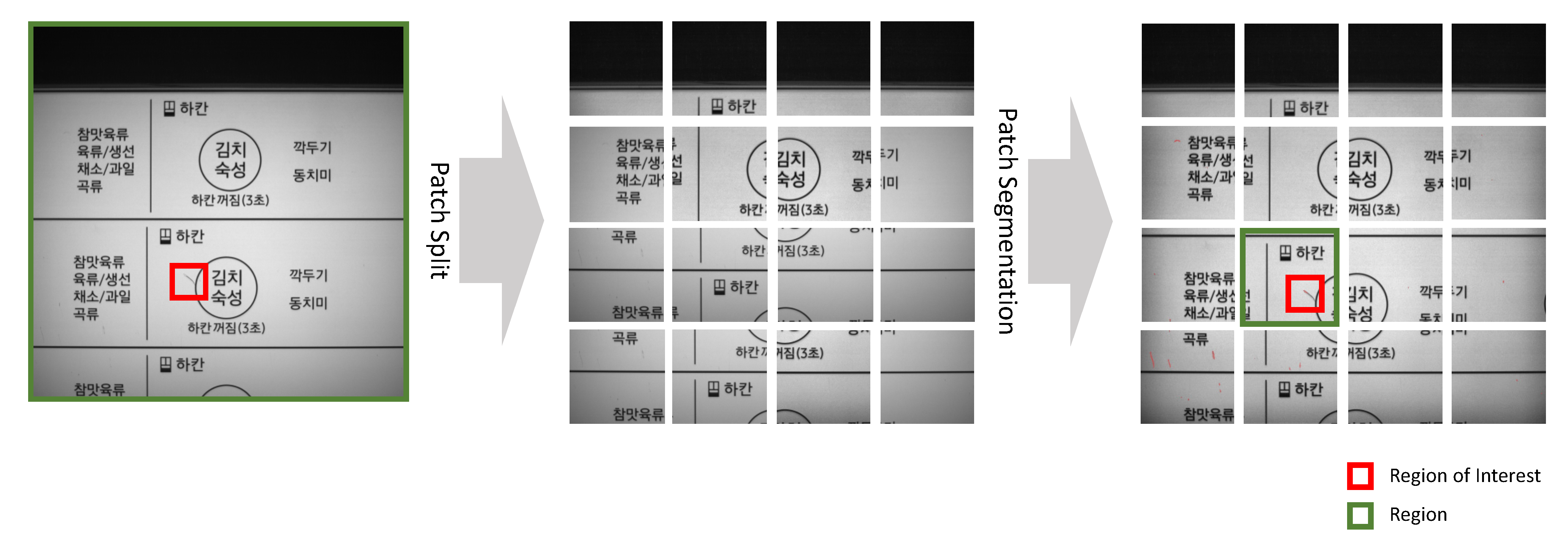
If training were to be performed by resizing the original 2448 × 2048 pixel image to 256 × 256 pixels, the information contained in the data would be lost, degrading the training performance of the model. In this study, to solve the degradation in learning performance, patch-unit images were used rather than the original image as input data. The learning method, illustrated in Figure 7, converts a 2448 × 2048 pixel image to a 1024 × 1024 pixel image through center cropping and resizing. Subsequently, the image is arbitrarily cropped into 256 × 256 pixel patch units for inference and training, to pass important information from the image to the model.
The preprocessed data are shown in Figure 8. The preprocessing consisted of performing center-crop, contrast limited adaptive histogram equalization (CLAHE), and resize [28]. Because of the lighting, the outer part of the collected image became increasingly darker, so a center crop (1900 × 1900 pixels) was performed as a first preprocessing step. It was determined that it would be difficult to detect defects because scratches, dents, and foreign substances were not clearly visible. The center crop made the process robust to noise when the pixel intensities were concentrated in a narrow range. Because the redistribution of the clustered pixel values converted the pixel intensity through a cumulative distribution function without a sharp gradient, the pixel intensity of noise could not be converted to a too large value. Therefore, the pixel intensity of the local region after CLAHE was not located between 0 and 255, but concentrated to within a narrower range. In other words, the advantage of using CLAHE was that it made the converted image have characteristics similar to the real image and made it robust to noise in a low-contrast area. A distinct difference between the image subjected to preprocessing and the original image is shown in Figure 8. Resizing to (1024 × 1024 pixels) was performed as the final preprocessing step to properly configure the CNN-type AI model input.
The loss function used for learning was applied by adding Dice loss, Dice binary cross-entropy (BCE) loss, IoU loss, and focal loss, rather than a single loss function, to ensure robustness to data imbalance [29,30,31]. Defects were found using a U-Net++ model trained through patch splits of preprocessed images. As shown in Figure 9, after each patch analysis was completed, all patches were combined to calculate the defects in the original image. The purpose was to increase the defect area compared to the entire input data area to improve the inference performance of the model. Increasing the defect area was advantageous for inference in including more image feature information regarding the defect.

3.3. Micro Defect Inspection Architecture and Process

In the case of silk screen prints, there are different types of products with different sizes. Therefore, a system for collecting product image data was utilized. The architecture of the system is illustrated in Figure 10. The components of the system include hardware for loading products, a 3-axis orthogonal robot that moves the vision camera to the shooting location, a vision camera that captures the product and creates an image that can be analyzed, a control for the vision camera, and PLC at the manufacturing site. The system consists of an AI edge PC capable of AI inference, a PLC that can control the 3-axis orthogonal robot and share the current situation with the AI Edge PC, and an AI server that can learn AI models by collecting and processing data from the cloud.
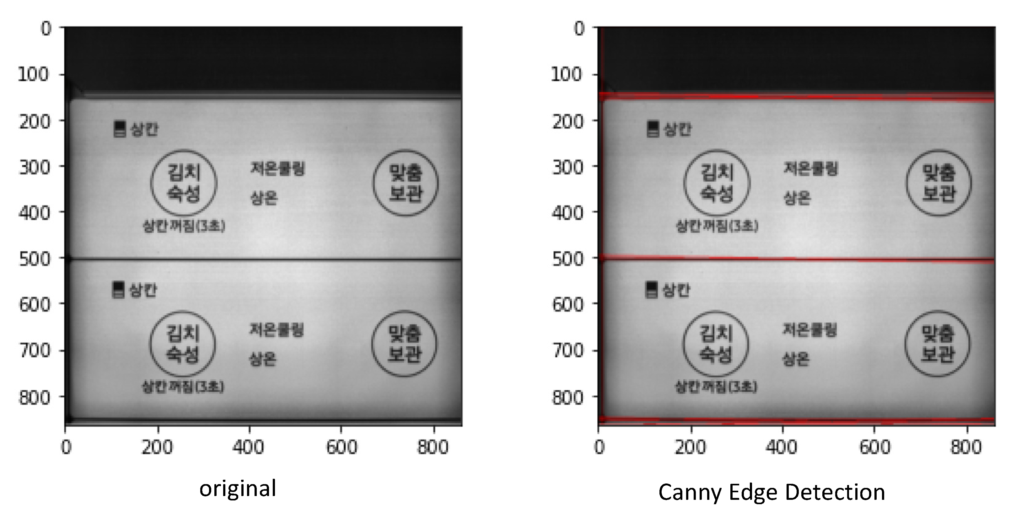
A quality inspection process for microdefects is also proposed. The overall inspection process of the system is illustrated in Figure 11. The system can acquire images regardless of the product size. For this purpose, a 3-axis orthogonal robot that can move along the x- and y-axes was introduced. In addition, if the height of the product changes, it is possible to move the robot along the z-axis to correspond to the focus. The process starts when the field worker loads the product and presses the start button on the PLC panel. Through the PLC signal, the 3-axis orthogonal robot moves to the first imaging area. Upon arriving at the location, the PLC sends location information to the AI Edge PC that controls the lighting, thereby turning on the lighting at the desired temperature. Subsequently, it sends a shooting request signal to the camera connected to the AI Edge PC. The captured image is stored in the volatile memory of the camera. The data are sent to an AI Edge PC. The raw image created in this manner has 2448 × 2048 pixels in the unprocessed state. Among the different types of defects in silk screen printing, we used blue light to detect defects that are not easily visible through the camera, such as scratches and dents. To maintain the external environment, a dark room in the form of a box was installed around the camera. Therefore, the raw image contained a shadow outside the product. To solve this problem, center crop was performed without loss of information. The cropped image had 1900 × 1900 pixels. Then, to improve the defect detection performance, CLAHE preprocessing was performed and after patch split, resizing was applied to suit the AI analysis model to input size. The preprocessed image size was 1024 × 1024 pixels. Subsequently, the proposed patch split described in Section 3.2 was performed. The patch image was composed of 256 × 256 pixels, with a total of 16 sheets. Defects were detected using the improved U-Net++ model learned by applying the existing patch-split method to the image divided by patch level. A threshold value of 0.15 or more was indicative of defect. The results were generated from 16 patch images and the original image. In the case of the original image, because there was more than one product, a separate process was required to determine which product was defective. That is, a further division into product units was required. For this purpose, HoughLinesP was applied after applying Canny edge detection. The Canny edge detector is an edge detection operator that uses a multistage algorithm to detect a wide range of edges in images [32]. An example of Canny edge detection is shown in Figure 12. Thus, it was possible to determine which product was defective in the image. If a defect was detected for a product, the location information value was sent to the PLC so that the operator could easily check for the defect by stamping it. The same process was followed for all products.

4. Performance Analysis

The methods and algorithms used in the proposed architecture were evaluated and validated for their effectiveness on various tasks, models, and datasets. Table 1 summarizes the specifications of the proposed system.
We performed performance analysis using Dice scores. The dice score and Jaccard index have become some of the most popular performance metrics in medical image segmentation. Zijdenbos et al. were among the first to suggest the dice score for medical image analysis by evaluating the quality of automated white matter lesion segmentations [27]. In scenarios with large class imbalances with an excessive number of (correctly classified) background voxels, they showed that the dice score is a special case of the kappa index, a chance-corrected measure of agreement. They further noted that the dice score reflected both the size and localization agreement, more in line with the perceptual quality compared to pixel-wise accuracy. The range of the dice score is between 0 and 1, and this is a probability value that collects how much the actual value and the predicted value overlap. It is 1 if the labeled area and the predicted area are the same; otherwise, it is 0. The dice score is the harmonic average of precision and recall and is expressed as follows. In binary image segmentation, y can be thought of as a set of pixels labeled as the foreground. It is, therefore, well-defined to consider set theoretic notions such as y     y ˜ for two different segmentations. This motivates the use of multiple set theoretic similarity measures between two segmentations named y and y ˜ . The equation for the dice score is as follows:
D ( y , y ˜ )   : =   2 | y     y ˜ | | y | + | y ˜ | .
Mainly, three hypotheses were considered for the Dice score with respect to data preprocessing, the model, and correlation between the loss function and model performance. The hypotheses were as follows:
  • The original image input, that is, the input to which the patch-split method is applied, increases the Dice score. The Dice score is often used to quantify the performance of image-segmentation methods.
  • Compared to the feature pyramid network (FPN) [33] and DeepLabV3, the U-net++ architecture increases the Dice score.
  • The Dice score can be increased by learning multiple loss functions and summing their values.
Because transfer learning is known to be efficient and effective in many deep learning computer vision studies, experiments were conducted with transfer learning using a pretrained network as a classification task [34]. The architecture of the backbone network was EfficientNet-b0. The reason for using EfficientNet-b0 was because the production cycle time of the site may increase during lengthy inspections; therefore, a fast reference time is required and a backbone network such as EfficientNet-b0 can ensure compliance. The learning rate was 0.0001 in float form, and the AdamW Optimizer was adopted [35]. For learning, an epoch consisted of 30 batch sizes of 2. The learning rate scheduler of the experiment utilized the cosine annealing learning rate, and as a scheduler is frequently used for various tasks, partial restarts are also gaining popularity in gradient-based optimization to improve the rate of convergence in accelerated gradient schemes to deal with ill-conditioned functions Therefore, the scheduler can solve overfitting by solving the local minima problem and as such, is suitable for the class imbalance problem. The experiment was conducted by setting a basic learning rate scheduler.
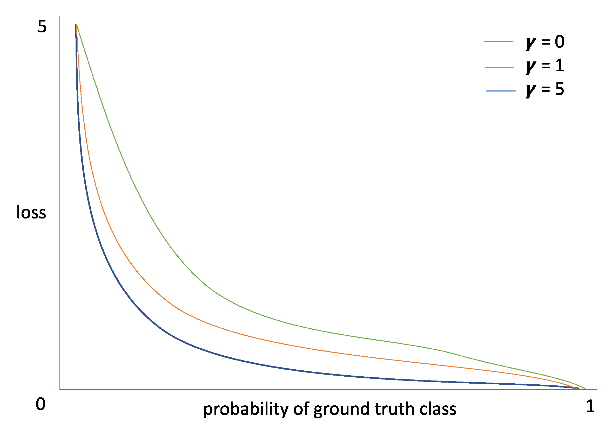
Regarding loss functions, the BCE, focal, and Tversky loss functions were examined. The BCE loss is a binary cross-entropy loss function. This method can be used for binary classification. Focal loss was proposed for object-detection tasks [36]. A background class imbalance problem exists in object detection and focal loss has been proposed to solve this problem. Focal loss reduces the weight of easy samples and focuses on learning hard negative examples. To increase the loss in the case of difficult fits, an exponential function was included in the loss, as shown in Figure 13. In object detection, the focal loss was calculated based on the bounding box, but segmentation was applied to our experiment by customizing the loss calculation at the pixel level.
The Tversky loss function is designed for class imbalance problems, such as focal loss, and is used in the field of medical image segmentation [37]. The Tversky loss function can be used not only for 2D segmentation problems but also for 3D image segmentation. In the medical field, Tversky loss is calculated similarly to the F2 and Dice scores, so it is suitable for optimizing the Dice score, which was a research goal of this study. The equation for the Tversky loss function is,
T ( α ,   β ) = i = 1 N p 0 i g 0 i i = 1 N p 0 i g 0 i + i = 1 N p 0 i g 1 i + i = 1 N p 1 i g 0 i
where the p 0 i is the probability of voxel i being a lesion and p 1 i is the probability of voxel i being a non-lesion in the output of the SoftMax layer. In addition, g 0 i is 1 for a lesion voxel and 0 for a non-lesion voxel and vice versa for g 1 i ; and α and β control the magnitude of the penalties for false positives (FP) and false negatives (FN), respectively.

4.1. Data Set

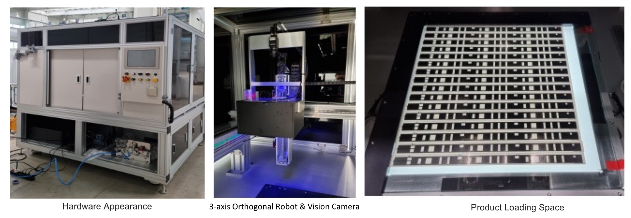
Figure 14 shows the actual appearance of the system consisting of the hardware that can load products and a 3-axis orthogonal robot that moves the camera. The types of well-identified defects differed depending on the color or location of the lighting. Therefore, tests were conducted according to the color and location of the lighting. Because white light source has a spectrum of all visible light, it is easy for the human eye to recognize an object. In addition, in the case of white home appliances, white light is often used because it is reflected from behind the product; therefore, white light was adopted as the backlight in our study. However, it was difficult to identify minute defects (scratches, dents, etc.) in the front part using white light. Light with a short wavelength is more easily dispersed when it hits a surface than light with a long wavelength. Therefore, blue light was used as the front light to facilitate surface detection.
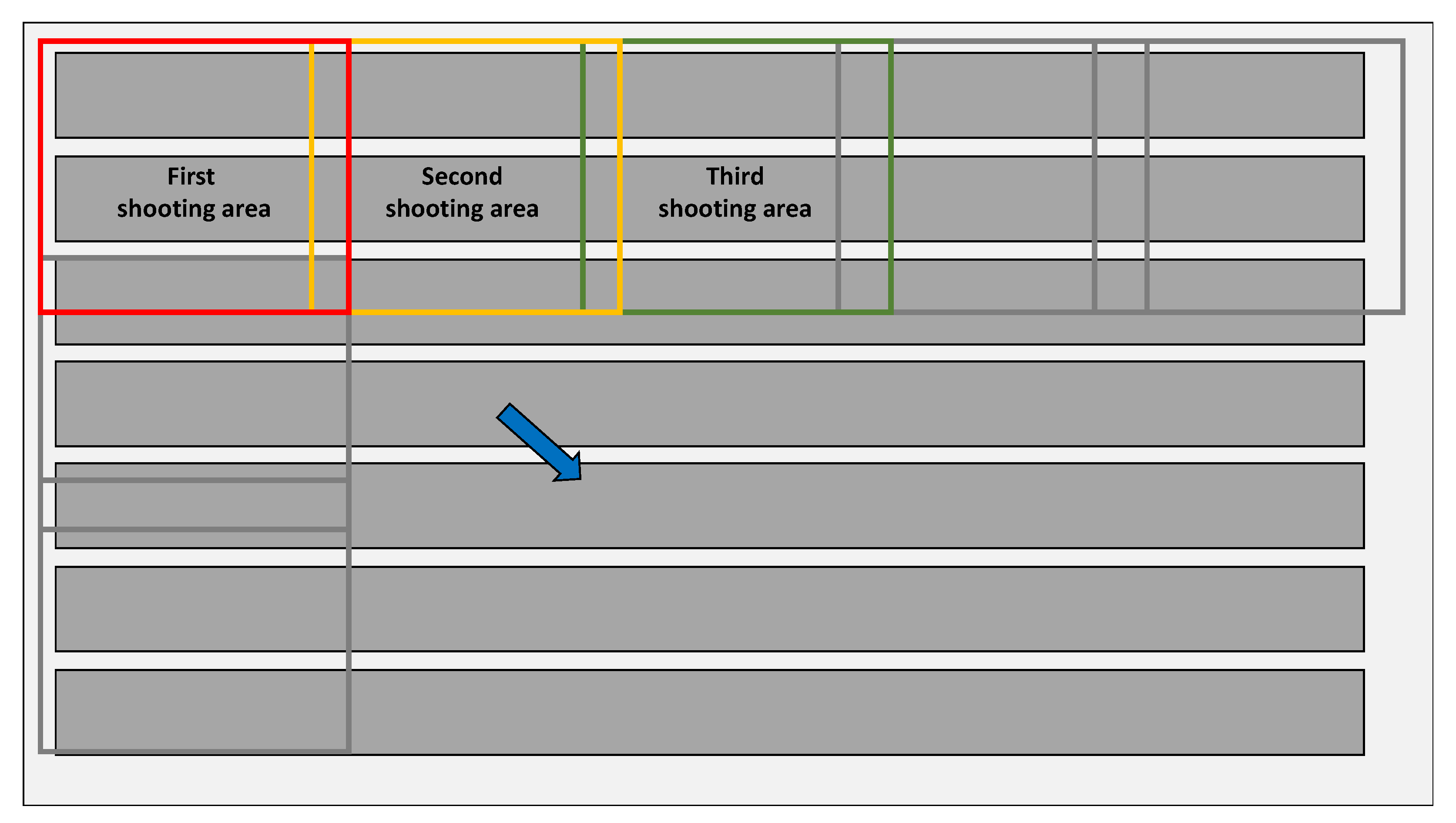
The method of gathering data to train and validate an AI model is shown in Figure 15. A sliding window was used to get to the product level rather than to the image level. The products were sequentially loaded and the 3-axis orthogonal robot was moved to the first shooting area through the PLC. An image was acquired through the vision camera, whereby the robot moved to the second imaging area. Similarly, images were acquired using the vision camera. The process described above was repeated until all loaded products were photographed. The shooting proceeds in the direction of the blue arrow, and the gray box indicates the nth shooting area. The purpose was to collect images to cover all areas of the product through patches corresponding to products of different sizes. Among the image preprocessing methods proposed to solve the problem of shadows caused by lighting, the outer part of the image is cut off due to center cropping. Therefore, to solve the problem, we proceeded to acquire data by partially overlapping each shooting area.
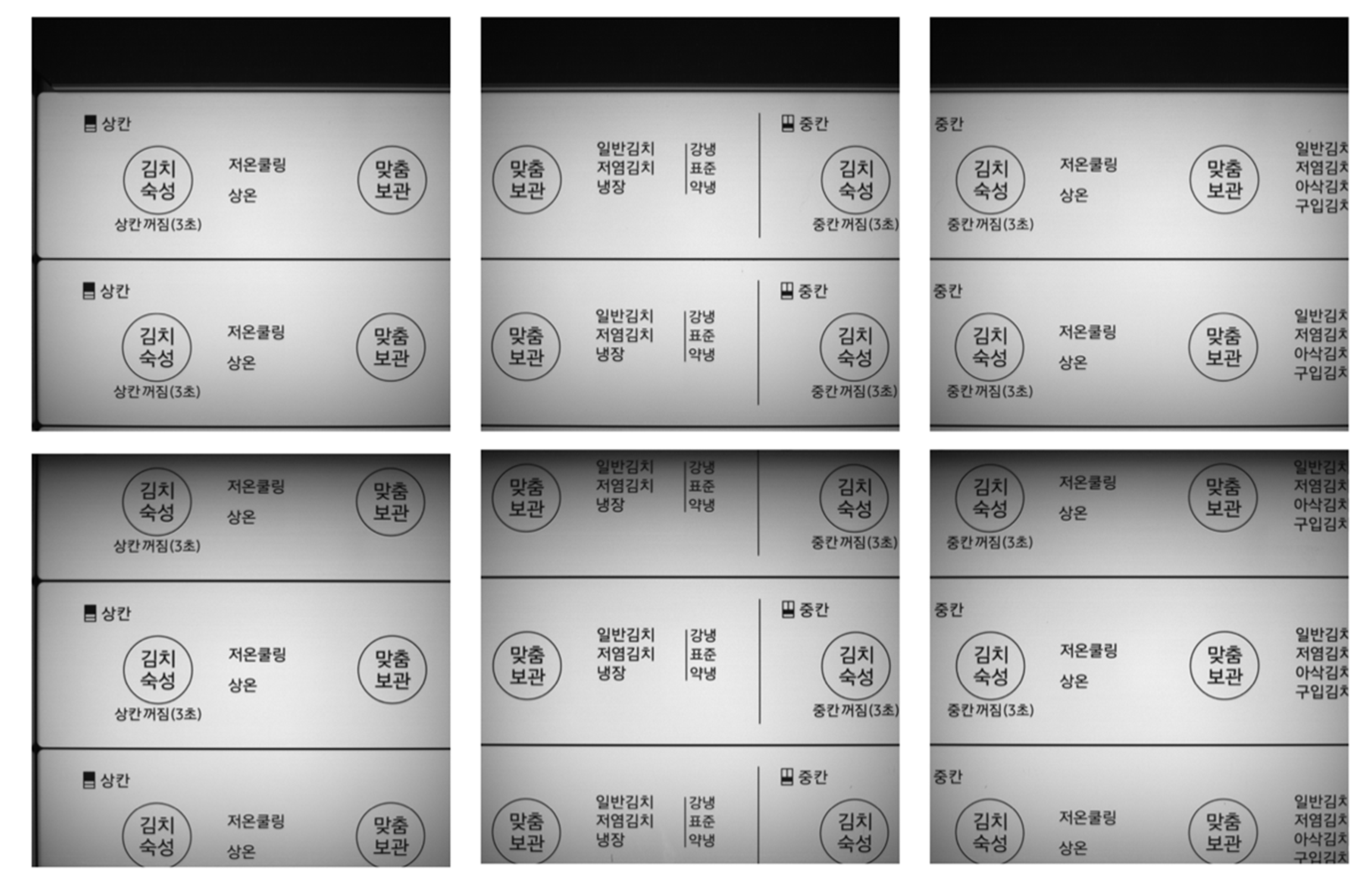
The collected data are shown in Figure 16. Each image consists of 2448 (w) × 2048 (h) pixels. The upper-left image is the first captured image and the upper-middle image is the second captured image. The upper-right image is the third photographed image and the lower-left image is the eighth photographed image.
Horizontal and vertical flips were used as data augmentation techniques. In addition, random rotate 90 was applied with a probability of 0.5 to augment the data before training.
The dataset used for verification had a total of 235 original images (1900 × 1900 pixels). Table 2 lists the data distribution for training and testing. In the case of general manufacturing data, data on defective products are scarce. Therefore, scalability to other fine defect-detection systems was also considered in experimenting with a small number of defect images for training and testing.

4.2. Evaluation Metrics

Although not added to the text, we conducted experiments based on precision, recall, and accuracy. However, the defect detection performance of the proposed model was quantitatively evaluated using the most appropriate Dice score, based on true positive (TP), false positive (FP), false negative (FN), and true negative (TN). TP is a test result that correctly indicates the presence of a condition or characteristic. FP is a test result that wrongly indicates that a particular condition or attribute is present. FN is a test result that wrongly indicates that a particular condition or attribute is absent. TN is a test result that correctly indicates the absence of a condition or characteristic. In our study, the defective part of the whole area was small, and the number of samples was not large, so class imbalance was extreme.

4.3. Experimental Results

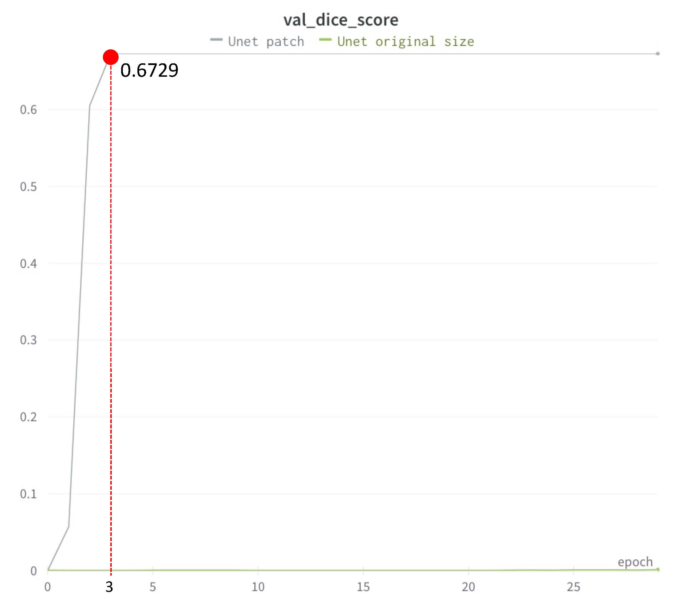
First, the effect of the patch-split method was analyzed while performing training and inference. In the conducted experiment, the architecture was fixed as U-Net and the loss function was fixed as BCE loss. Figure 17 depicts the case of the original input. It was not possible to learn the characteristics of the image well. However, in the case of learning by applying the patch-split method, the performance steadily increased as the learning progressed. It was observed that the maximum Dice score was attained in epoch 3.
The effects of the patch-split method are presented in Table 3. The original input had a very low Dice score of 0.001376, whereas the patch-split method had a Dice score of 0.6729.
In the inference result image of Figure 18, even the non-defective parts were inferred as defects when using the original input. On the other hand, the defects were properly detected using our proposed patch-split method.
The loss function was fixed as the BCE loss and was analyzed for each architecture. As shown in Table 3, the FPN showed the best performance with a Dice score of 0.679, similar to U-Net ++. As shown in Figure 19, when the FPN architecture was used, defects were detected, but the performance could have be better, and the segmentation area deviated slightly from the defect area. With the proposed method, all types of defects within the defect data set were detected.
As shown in Figure 20, the Dice score of DeepLabV3 and FPN did not reach 0.7 from the start to the end of learning. However, in our proposed method, it was confirmed that the Dice score was stable at over 0.72 after completely learning in more than 2000 steps.
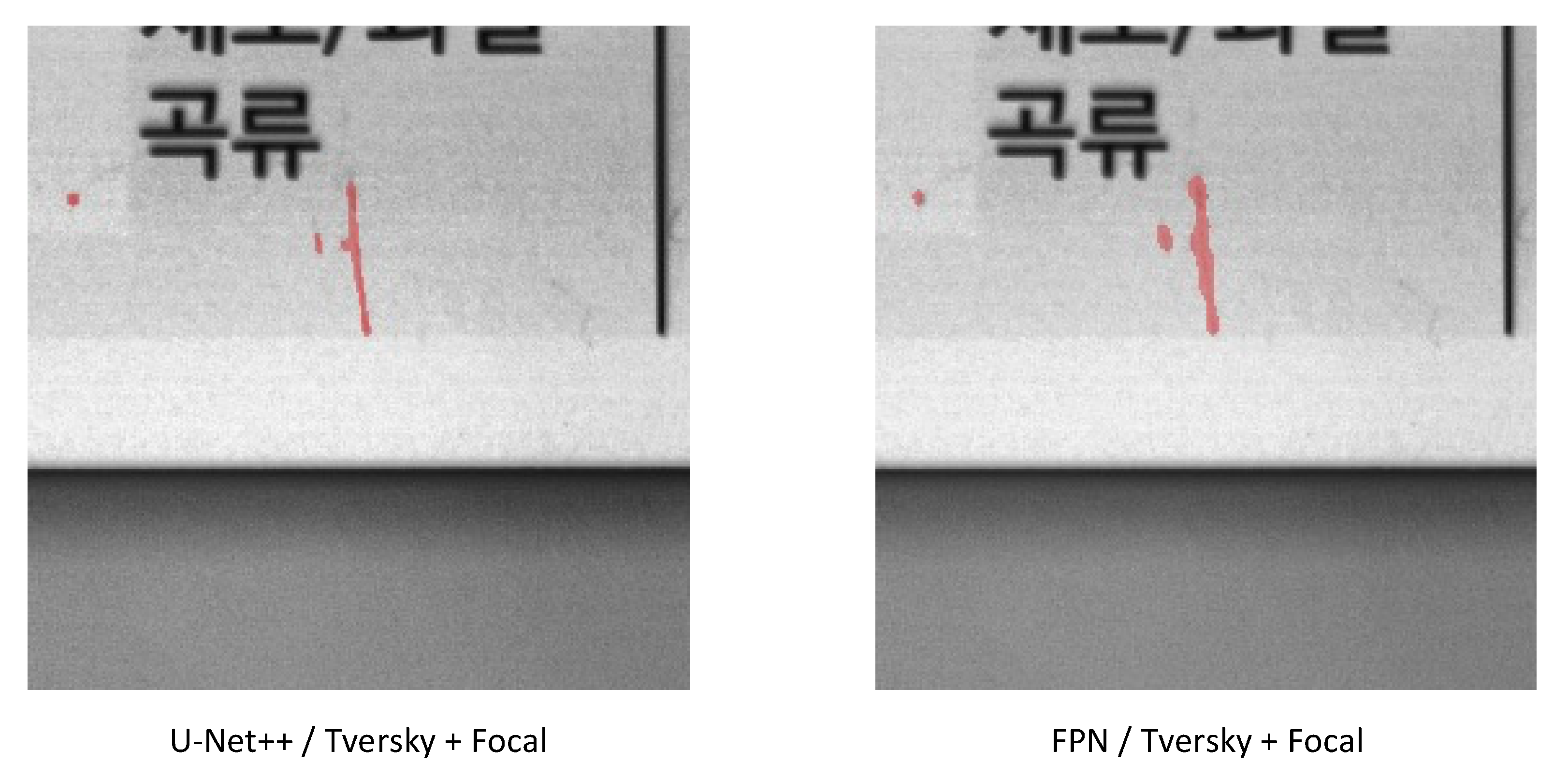
As shown in Table 4, the difference was large for each loss function. The proposed loss function is a combination of focal loss and Tversky loss. In the experiment of the study “A Novel focal Tversky loss function with improved attention U-Net for lesion segmentation” [38], the combined form of the two loss functions seemed to be more effective and was better than the Tversky loss function; therefore, we used it for the combined loss. The analysis was conducted using a combination of Tversky loss and focal loss, which are loss functions suitable for segmentation. As a result, the defect detection performance was better than that of the previous analysis, regardless of the architecture. The Dice score of our proposed U-Net++ architecture was the highest at 0.728.
As shown in Figure 21, the proposed method only found defects and the segmentation area was correct.

5. Conclusions

In this study, an improved U-Net++ model applying the patch-split method is proposed. When using an existing original image as it was, it failed to detect fine defects, and even an area that was not defective was registered as defective. By applying the proposed patch-split method, it could be seen that the dice score was improved by 0.67 or more when compared to previous studies. In addition, a Dice score of 0.728 was achieved by learning through a complex loss function rather than a single loss function. In this study, detection performance was improved through the pretreatment of data with small defects in the product that are difficult to see under light.
In the era of the fourth industrial revolution, various convergence technologies have been applied to the manufacturing industry. However, there are many cases in which the defects of the product are irregular or too fine to be located because it is difficult to determine the characteristics in an image. However, in the future, through our research, it will be possible to fully detect products with fine defects compared to the size of the product, such as silkscreen prints. The proposed detection process is also expected to improve the consistency of data collection and processing. In addition, it was shown that quality inspection using patch-split method-based AI is possible, even in situations where there is very little prior data on defective products, which is a common occurrence in the manufacturing industry.
Small defects were detected well with the proposed method, but dust generated by the inspection equipment and workers was also detected; therefore, the inspection system needs to be improved. It appears that the weakness of the model can be supplemented through additional learning on collected data with dust to classify it into defects.
In future research, to complement the weaknesses of the current research, the data collected in the field will be auto-labeled through data-centric MLOps to address model changes of manufacturing sites through auto-training. In addition, a comparison of the results with the current state-of-the-art models will be performed to prove the superiority of the proposed model [39].

Author Contributions

Conceptualization, B.Y. and J.J.; methodology, B.Y. and H.L.; software, B.Y. and H.L.; validation, B.Y.; H.L.; and J.J.; formal analysis, B.Y. and H.L.; investigation, B.Y.; resources, J.J.; data curation, B.Y.; writing—original draft preparation, B.Y.; writing—review and editing, J.J.; visualization, B.Y.; supervision, J.J.; project administration, J.J.; funding acquisition, J.J. All authors have read and agreed to the published version of the manuscript.

Funding

This research was supported by the Ministry of Science and ICT (MIST), Korea, under the ICT Creative Consilience Program (IITP-2022-2020-0-01821) supervised by the IITP (Institute for Information & Communications Technology Planning & Evaluation), and the National Research Foundation of Korea (NRF) grant funded by the Korean government (MSIT) (No. 2021R1F1A1060054).

Institutional Review Board Statement

Not applicable.

Informed Consent Statement

Not applicable.

Data Availability Statement

Not applicable.

Acknowledgments

This research was supported by the SungKyunKwan University and the BK21 FOUR (Graduate School Innovation) funded by the Ministry of Education (MOE, Korea) and National Research Foundation of Korea (NRF).

Conflicts of Interest

The authors declare no conflict of interest.

References

  1. Kapitanov, A. Special characteristics of the multi-product manufacturing. Procedia Eng. 2016, 150, 832–836. [Google Scholar] [CrossRef] [Green Version]
  2. Riew, M.C.; Lee, M.K. A Case Study of the Construction of Smart Factory in a Small Quantity Batch Production System: Focused on IDIS Company. J. Korean Soc. Qual. Manag. 2018, 46, 11–26. [Google Scholar]
  3. Krebs, F.C.; Alstrup, J.; Spanggaard, H.; Larsen, K.; Kold, E. Production of large-area polymer solar cells by industrial silk screen printing, lifetime considerations and lamination with polyethyleneterephthalate. Sol. Energy Mater. Sol. Cells 2004, 83, 293–300. [Google Scholar] [CrossRef]
  4. Czimmermann, T.; Ciuti, G.; Milazzo, M.; Chiurazzi, M.; Roccella, S.; Oddo, C.M.; Dario, P. Visual-based defect detection and classification approaches for industrial applications—A survey. Sensors 2020, 20, 1459. [Google Scholar] [CrossRef] [PubMed] [Green Version]
  5. Guo, F.; Qian, Y.; Wu, Y.; Leng, Z.; Yu, H. Automatic railroad track components inspection using real-time instance segmentation. Comput. Aided Civ. Infrastruct. Eng. 2021, 36, 362–377. [Google Scholar] [CrossRef]
  6. Bergmann, P.; Fauser, M.; Sattlegger, D.; Steger, C. MVTec AD—A comprehensive real-world dataset for unsupervised anomaly detection. In Proceedings of the IEEE/CVF Conference on Computer Vision and Pattern Recognition, Long Beach, CA, USA, 15–20 June 2019; pp. 9592–9600. [Google Scholar]
  7. Agnisarman, S.; Lopes, S.; Madathil, K.C.; Piratla, K.; Gramopadhye, A. A survey of automation-enabled human-in-the-loop systems for infrastructure visual inspection. Autom. Constr. 2019, 97, 52–76. [Google Scholar] [CrossRef]
  8. Defard, T.; Setkov, A.; Loesch, A.; Audigier, R. Padim: A patch distribution modeling framework for anomaly detection and localization. In Proceedings of the International Conference on Pattern Recognition, Milan, Italy, 10–15 January 2021; pp. 475–489. [Google Scholar]
  9. Bochkovskiy, A.; Wang, C.-Y.; Liao, H.-Y.M. Yolov4: Optimal speed and accuracy of object detection. arXiv 2020, arXiv:2004.10934. [Google Scholar]
  10. Redmon, J.; Divvala, S.; Girshick, R.; Farhadi, A. You only look once: Unified, real-time object detection. In Proceedings of the IEEE Conference on Computer Vision and Pattern Recognition, Las Vegas, NV, USA, 27–30 June 2016; pp. 779–788. [Google Scholar]
  11. Liang, Y.; He, R.; Li, Y.; Wang, Z. Simultaneous segmentation and classification of breast lesions from ultrasound images using mask R-CNN. In Proceedings of the 2019 IEEE International Ultrasonics Symposium (IUS), Glasgow, UK, 6–9 October 2019; pp. 1470–1472. [Google Scholar]
  12. Chen, L.-C.; Papandreou, G.; Schroff, F.; Adam, H. Rethinking atrous convolution for semantic image segmentation. arXiv 2017, arXiv:1706.05587. [Google Scholar]
  13. Yang, H.; Min, K. A Saliency-Based Patch Sampling Approach for Deep Artistic Media Recognition. Electronics 2021, 10, 1053. [Google Scholar] [CrossRef]
  14. Krizhevsky, A.; Sutskever, I.; Hinton, G.E. Imagenet classification with deep convolutional neural networks. Adv. Neural Inf. Process. Syst. 2012, 25, 84–90. [Google Scholar] [CrossRef]
  15. Liu, Y.; Sun, P.; Wergeles, N.; Shang, Y. A survey and performance evaluation of deep learning methods for small object detection. Expert Syst. Appl. 2021, 172, 114602. [Google Scholar] [CrossRef]
  16. Ronneberger, O.; Fischer, P.; Brox, T. U-net: Convolutional networks for biomedical image segmentation. In Proceedings of the International Conference on Medical Image Computing and Computer-Assisted Intervention, Munich, Germany, 5–9 October 2015; pp. 234–241. [Google Scholar]
  17. Zhou, Z.; Rahman Siddiquee, M.M.; Tajbakhsh, N.; Liang, J. Unet++: A nested u-net architecture for medical image segmentation. In Deep Learning in Medical Image Analysis and Multimodal Learning for Clinical Decision Support; Springer: Berlin/Heidelberg, Germany, 2018; pp. 3–11. [Google Scholar]
  18. Roy, A.M.; Bhaduri, J. Real-time growth stage detection model for high degree of occultation using DenseNet-fused YOLOv4. Comput. Electron. Agric. 2022, 193, 106694. [Google Scholar] [CrossRef]
  19. Carlini, N.; Wagner, D. Towards evaluating the robustness of neural networks. In Proceedings of the 2017 IEEE Symposium on Security and Privacy (sp), San Jose, CA, USA, 22–26 May 2017; pp. 39–57. [Google Scholar]
  20. Im, D.; Lee, S.; Lee, H.; Yoon, B.; So, F.; Jeong, J. A data-centric approach to design and analysis of a surface-inspection system based on deep learning in the plastic injection molding industry. Processes 2021, 9, 1895. [Google Scholar] [CrossRef]
  21. Masci, J.; Meier, U.; Cireşan, D.; Schmidhuber, J. Stacked convolutional auto-encoders for hierarchical feature extraction. In Proceedings of the International Conference on Artificial Neural Networks, Espoo, Finland, 14–17 June 2011; pp. 52–59. [Google Scholar]
  22. Kingma, D.P.; Welling, M. Auto-encoding variational bayes. arXiv 2013, arXiv:1312.6114. [Google Scholar]
  23. Misra, I.; Maaten, L.V.D. Self-supervised learning of pretext-invariant representations. In Proceedings of the IEEE/CVF Conference on Computer Vision and Pattern Recognition, Seattle, WA, USA, 13–19 June 2020; pp. 6707–6717. [Google Scholar]
  24. Long, J.; Shelhamer, E.; Darrell, T. Fully convolutional networks for semantic segmentation. In Proceedings of the IEEE Conference on Computer Vision and Pattern Recognition, Boston, MA, USA, 7–12 June 2015; pp. 3431–3440. [Google Scholar]
  25. Biegeleisen, J.I. The Complete Book of Silk Screen Printing Production; Courier Corporation: Chelmsford, MA, USA, 2012. [Google Scholar]
  26. Minoura, D.; Nagahashi, H.; Agui, T.; Nagao, T. An Automatic Detection of Defects on Silk Screen Printed Plate Surfaces. Jpn. Soc. Print. Sci. Technol. 1993, 30, 1315. [Google Scholar] [CrossRef]
  27. Eugene Chian, Y.T.; Tian, J. Surface Defect Inspection in Images Using Statistical Patc hes Fusion and Deeply Learned Features. AI 2021, 2, 17–31. [Google Scholar] [CrossRef]
  28. Reza, A.M. Realization of the contrast limited adaptive histogram equalization (CLAHE) for real-time image enhancement. J. VLSI Signal Processing Syst. Signal Image Video Technol. 2004, 38, 35–44. [Google Scholar] [CrossRef]
  29. Bertels, J.; Eelbode, T.; Berman, M.; Vandermeulen, D.; Maes, F.; Bisschops, R.; Blaschko, M.B. Optimizing the dice score and jaccard index for medical image segmentation: Theory and practice. In Proceedings of the International Conference on Medical Image Computing and Computer-Assisted Intervention, Shenzhen, China, 13–17 October 2019; pp. 92–100. [Google Scholar]
  30. Sudre, C.H.; Li, W.; Vercauteren, T.; Ourselin, S.; Jorge Cardoso, M. Generalised dice overlap as a deep learning loss function for highly unbalanced segmentations. In Deep Learning in Medical Image Analysis and Multimodal Learning for Clinical Decision Support; Springer: Berlin/Heidelberg, Germany, 2017; pp. 240–248. [Google Scholar]
  31. Zhou, D.; Fang, J.; Song, X.; Guan, C.; Yin, J.; Dai, Y.; Yang, R. Iou loss for 2d/3d object detection. In Proceedings of the 2019 International Conference on 3D Vision (3DV), Québec, QC, Canada, 16–19 September 2019; pp. 85–94. [Google Scholar]
  32. Li, Y.; Chen, L.; Huang, H.; Li, X.; Xu, W.; Zheng, L.; Huang, J. Nighttime lane markings recognition based on Canny detection and Hough transform. In Proceedings of the 2016 IEEE International Conference on Real-time Computing and Robotics (RCAR), Angkor Wat, Cambodia, 6–9 June 2016; pp. 411–415. [Google Scholar]
  33. Lin, T.-Y.; Dollár, P.; Girshick, R.; He, K.; Hariharan, B.; Belongie, S. Feature pyramid networks for object detection. In Proceedings of the IEEE Conference on Computer Vision and Pattern Recognition, Honolulu, HI, USA, 21–26 July 2017; pp. 2117–2125. [Google Scholar]
  34. Yosinski, J.; Clune, J.; Bengio, Y.; Lipson, H. How transferable are features in deep neural networks? Adv. Neural Inf. Processing Syst. 2014, 27, 3320–3328. [Google Scholar]
  35. Llugsi, R.; El Yacoubi, S.; Fontaine, A.; Lupera, P. Comparison between Adam, AdaMax and Adam W optimizers to implement a Weather Forecast based on Neural Networks for the Andean city of Quito. In Proceedings of the 2021 IEEE Fifth Ecuador Technical Chapters Meeting (ETCM), Cuenca, Ecuador, 12–15 October 2021; pp. 1–6. [Google Scholar]
  36. Lin, T.-Y.; Goyal, P.; Girshick, R.; He, K.; Dollár, P. Focal loss for dense object detection. In Proceedings of the IEEE International Conference on Computer Vision, Venice, Italy, 22–29 October 2017; pp. 2980–2988. [Google Scholar]
  37. Salehi, S.S.M.; Erdogmus, D.; Gholipour, A. Tversky loss function for image segmentation using 3D fully convolutional deep networks. In Proceedings of the International Workshop on Machine Learning in Medical Imaging, Quebec City, QC, Canada, 10 September 2017; pp. 379–387. [Google Scholar]
  38. Abraham, N.; Khan, N.M. A novel focal tversky loss function with improved attention u-net for lesion segmentation. In Proceedings of the 2019 IEEE 16th International Symposium on Biomedical Imaging (ISBI 2019), Venice, Italy, 8–11 April 2019; pp. 683–687. [Google Scholar]
  39. Raj, E.; Buffoni, D.; Westerlund, M.; Ahola, K. Edge MLOps framework for AIoT applications. In Proceedings of the 2021 IEEE International Conference on Cloud Engineering (IC2E), San Francisco, CA, USA, 4–8 October 2021. [Google Scholar] [CrossRef]
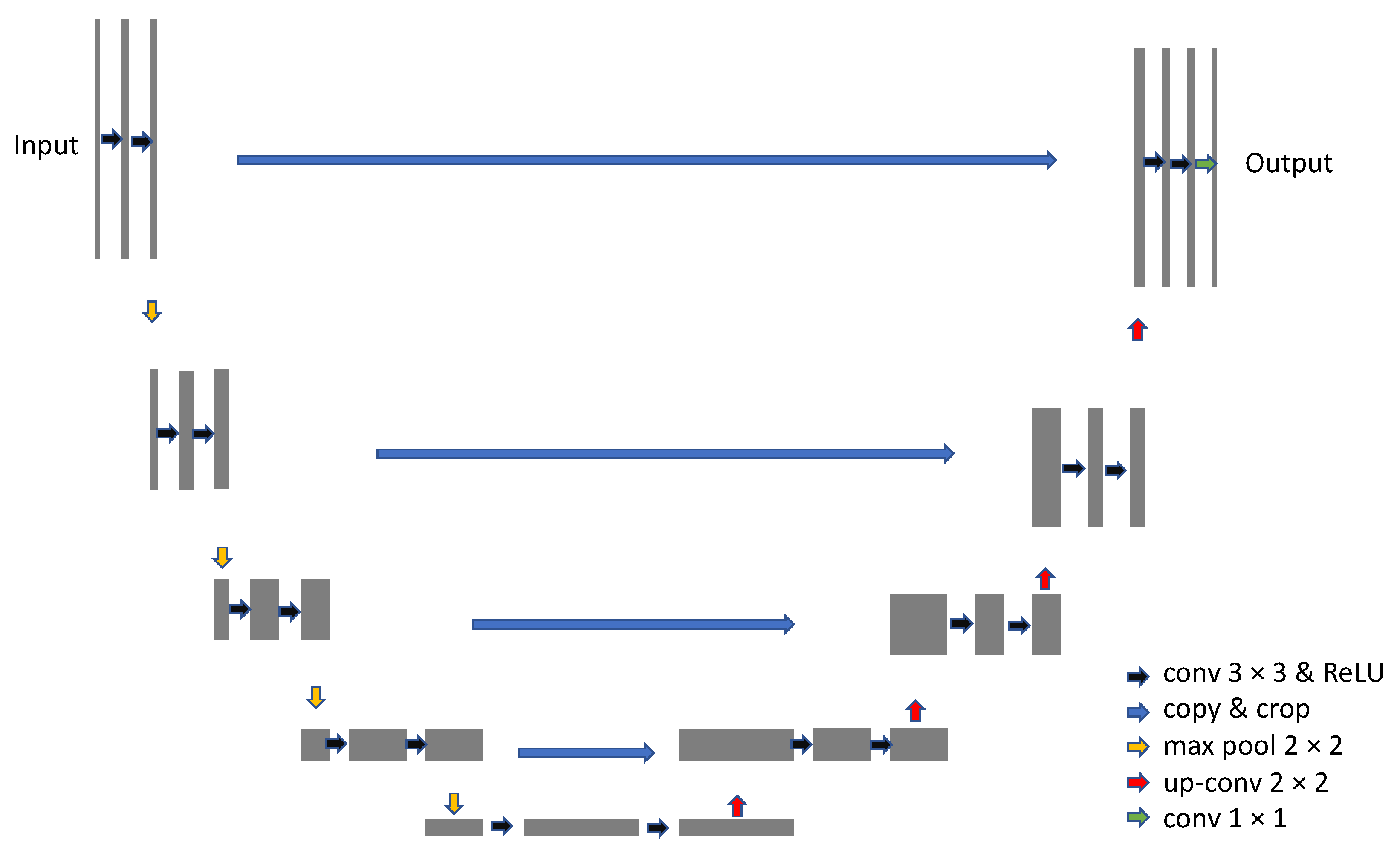
Figure 1. U-Net Architecture Reprinted with permission from Ref. [16]. 2015, Ronneberger, O.
Applsci 12 04679 g001
Figure 2. U-Net++ architecture Reprinted with permission from Ref. [17]. 2018, Zhou, Z.
Applsci 12 04679 g002
Figure 3. Silkscreen printing method.
Applsci 12 04679 g003
Figure 4. Examples of types of defects.
Applsci 12 04679 g004
Figure 5. Patch sampling.
Applsci 12 04679 g005
Figure 6. Architecture of the proposed system.
Applsci 12 04679 g006
Figure 7. Proposed detailed learning method.
Applsci 12 04679 g007
Figure 8. Improved contrast with contrast-limited adaptive histogram equalization (CLAHE) [28].
Applsci 12 04679 g008
Figure 9. Proposed detailed inference method.
Applsci 12 04679 g009
Figure 10. Implemented systems for data acquisition, model training, and inference.
Applsci 12 04679 g010
Figure 11. Proposed micro-defect detection process.
Applsci 12 04679 g011
Figure 12. Canny edge detection example.
Applsci 12 04679 g012
Figure 13. Focal loss Reprinted with permission from Ref. [36]. 2017, Lin, T.-Y.
Applsci 12 04679 g013
Figure 14. Appearance of the system consisting of the hardware.
Applsci 12 04679 g014
Figure 15. Data acquisition method.
Applsci 12 04679 g015
Figure 16. Product images collected using a vision camera.
Applsci 12 04679 g016
Figure 17. Training log (patch-split and original size input).
Applsci 12 04679 g017
Figure 18. Images detected using original input and patch-split input.
Applsci 12 04679 g018
Figure 19. Images detected using patch-split method and a single loss function.
Applsci 12 04679 g019
Figure 20. Training log (proposed method, DeepLabV3 and FPN).
Applsci 12 04679 g020
Figure 21. Image detected by patch-split method and multiple loss functions.
Applsci 12 04679 g021
Table 1. System specifications.
Hardware EnvironmentSoftware Environment
CPU: Intel Core i9-10900 ProcessorUbuntu 20.04
GPU: Nvidia GeForce RTX 3080Python 3.7
RAM: Samsung Electronics DDR4 32 GBCUDA 11.2
SSD: Samsung Electronics 970 EVO
series 1 TB M.2 NVMe
Pytorch 1.8.1
HDD: Western Digital BLUE HDD 4 TBAlbumentation 1.1
Vision Camera: Lucid TRI122S-MC 12 MP
Customized mechanical part
for quality inspection
Table 2. Training and test data sets.
NormalAbnormalTotal
Total115234349
Training75188263
Test404686
Table 3. Comparison of original input and patch-split input.
MethodArchitectureLoss FunctionDice Score
Original InputU-NetBCE0.001376
Patch Split InputU-NetBCE0.6729
Table 4. Experimental results.
ArchitectureLoss FunctionDice Score
U-NetBCE0.6729
FPNBCE0.679
DeepLabV3BCE0.6729
U-Net++BCE0.6729
U-Net++Focal0.6729
U-Net++Tversky0.7185
FPNTversky + Focal0.7071
(Our Proposal) U-Net++Tversky + Focal0.728
Publisher’s Note: MDPI stays neutral with regard to jurisdictional claims in published maps and institutional affiliations.