1. Introduction
In optical measurement and machine vision, there is a kind of classical pose estimation problem named PNP (Perspective of N Points) problem, proposed by Fishler and Bolles [
1]. The PNP problem can be described as how to estimate the pose parameters between object and camera if there are N points on an object and their corresponding projections in the image captured by the camera.
Because at least three points are needed to determine the full pose parameters of an object, if N ≤ 2, the PNP problem will have no determinate solution, while, if N ≥ 6 and the points are non-coplanar, the PNP problem can be easily solved by a direct linear transformation (DLT) algorithm. As a result, the P3P, P4P and P5P problems receive the most attention in the literature.
For the P4P problem, if the four points are non-coplanar, the P4P problem can be translated into a problem of solving a biquadratic equation with five groups of solutions at most [
2,
3,
4]. Otherwise, a unique solution will exist if the four points are coplanar. Linear algorithms can solve not only the rotation matrix and the translation vector, but also any two intrinsic parameters of the camera, e.g., the equivalent focal lengths can be solved [
5,
6].
In addition, the non-coplanar P4P problem may have a unique solution if the points meet some spatial distribution restrictions [
7]. If a PNP problem has a unique solution, linear algorithms can obtain the solution [
8,
9,
10]. The PNP problems with multi-groups of solutions are usually solved by iterative algorithms with initial values [
11,
12], such as the Bundle Adjustment (BA) method [
13,
14]. In recent years, methods for PNP problems have been used in indoor positioning, navigation and monitoring [
15,
16,
17,
18].
In this paper, the coplanar P4P problem is studied when the four points are just the four vertices of a parallelogram. For traditional P4P algorithms, the four points’ coordinates must be known, or the four points must form a rectangle [
19,
20]. For the pose and shape estimation of parallelogram objects with unknown shape parameters, such as some parallelogram structures on buildings as shown in
Figure 1 and the parallelogram formed by a walking man’s body standing at two positions (discussed at the end of this paper), the solution conditions for traditional P4P methods do not exist.
According to the projection relationships and the relative coordinate constraints of the parallelogram’s vertices, a new monocular pose estimation method is presented in this paper to solve the coplanar P4P problem of a parallelogram object without shape parameters. By the new method, a parallelogram object’s pose parameters (translation vectors and rotation angles relative to the camera) and shape parameters (the four vertices’ coordinates) can be obtained from one image of the object when one of the parallelogram’s side lengths is known. If there is no known scale information, a scale factor between the estimation results and the real values will exist.
2. Methodology
In the new method, the camera system will be taken as a reference system to simplify the expression of the projection relationships. Similarly, the number of unknown values will be reduced according to the relative coordinate constraints of the parallelogram’s four vertices. Then, a set of linear equations will be established and solved. After that, the coordinates of the four vertices can be obtained by using a side length of the parallelogram. With the coordinates of the four vertices, an object system can be established on the parallelogram and the coordinates of each vertex in the object system can be calculated. With the four vertices’ coordinates in the camera system and the object system respectively, the transformation parameters between the two systems can be obtained, including the position and attitude parameters of the object relative to the camera.
In general, the new method to estimate a parallelogram object’s pose parameters includes two steps: Step 1. To calculate the real coordinates of the parallelogram’s four vertices by taking the camera system as a reference system, and Step 2. To calculate the parallelogram’s pose parameters relative to the camera based on the four vertices’ known coordinates in the camera system and the object system, respectively.
2.1. To Calculate the Real Coordinates of the Parallelogram’s Four Vertices
- (1)
Projection relationships of a parallelogram’s four vertices
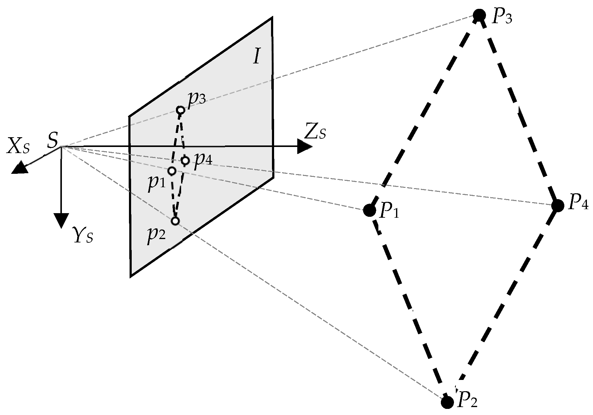
As shown in
Figure 2, a parallelogram’s four vertices are
P1 to
P4, where
P1P2∥
P3P4, |
P1P2| = |
P3P4| and
P1P3∥
P2P4, |
P1P3| = |
P2P4|. The camera system
S-XYZ is taken as a reference system. The image plane is
I. The corresponding projections of
P1 to
P4 are
p1 to
p4.
In the reference system, the coordinates of
Pi are
Mi = [
XSi YSi ZSi]
T, where
i = 1, 2, 3, 4. The image coordinates of the corresponding projections are
mi = [
ui vi]
T. A pin-hole camera model is used. Because the camera system is taken as the reference system, the translation vector
TS is a zero vector, and the rotation matrix
RS is an identity matrix. Then, the projection relationships are
where
and
are the augment matrices of
mi and
Mi.
λi is a scale factor.
K is the camera’s known intrinsic matrix.
For a parallelogram, the coordinates of the four vertices meet the following relationship.
By denoting
t = [
tX tY tZ]
T =
M3 −
M1 =
M4 −
M2, the projection relationships are
where
is the augment matrix of
t.
- (2)
Solution of the parallelogram vertices’ coordinates in the camera system
Because the object is in front of the camera, the
Z coordinates of the four vertices are positive. Then, eight intermediate variables can be defined as follows.
The scale factor
λi can be eliminated from Equation (3) and the equations can be expressed as
where
α,
β and
γ are constant coefficients combined by the camera’s intrinsic parameters. Thus, a set of linear equations of the intermediate variables are obtained. Moreover, the intermediate variables can be obtained analytically.
By setting the length of
P1P2 to
L, the following expression can be obtained based on the definition of the intermediate variables.
Then, the coordinates of the four vertices in the camera system are obtained.
If L is precisely known, the real coordinates of the parallelogram’s four vertices in the camera system can be obtained. In fact, if a distance between any two of the four vertices is known, a unique solution will exist for such a P4P problem, and if no scale information is known, a scale factor will exist between the vertices’ real coordinates and the estimation results.
2.2. To Calculate the Parallelogram’s Pose Parameters Relative to the Camera
As shown in
Figure 3, the coordinates of the parallelogram’s four vertices in the camera system
S-XSYSZS have been obtained. Then, their coordinates in the parallelogram’s object system
B-XBYBZB can be obtained based on the definition of the object system. The object’s pose parameters relative to the camera, the rotation matrix
RB and the translation vector
TB, that
can be calculated by coordinate transformation from the four vertices’ coordinates in the two systems, respectively.
Here, if no scale information is known, an unknown scale factor will exist between the estimation results of the object’s position and the real values. While the estimation results of the object’s attitude angles are independent of any scale information.
Additionally, the parallelogram object’s shape parameters can also be obtained after all the vertices’ positions are obtained.
3. Experimental Results
In the experiments, a parallelogram object is used. The object’s vertices’ coordinates in the object coordinate system are
P1 (−70 mm, 120 mm, 0),
P2 (−70 mm, −60 mm, 0),
P3 (70 mm, 60 mm, 0) and
P4 (70 mm, −120 mm, 0), as shown in
Figure 4.
A camera with known intrinsic parameters is used to capture images of the object. The proposed method is used to estimate the parallelogram object’s pose parameters relative to the camera and the coordinates of the four vertices. As a comparison, a traditional iterative algorithm is used to estimate the object’s pose parameters. The “iterative algorithm” is actually the bundle adjustment method, a kind of iterative correction and optimization algorithm from initial values, which is famous in photogrammetry and computer vision for its performance of high accuracy. For the traditional method, the parallelogram vertices’ coordinates are taken as known, only the parallelogram’s pose parameters are to be solved.
One of the experimental images is shown in
Figure 5, where the white crosses show the extracting positions of the parallelogram vertices.
The estimation results in experiments are shown in
Table 1 which consists of:
- (1)
The translation vectors (TBX, TBY, TBZ) and rotation angles (ABX, ABY, ABZ) between the object and the camera estimated by the new method (noted by New P4P in the table).
- (2)
The translation vectors and rotation angles estimated by the traditional method (noted by Old P4P in the table) taking all of the vertices as known.
- (3)
The difference between the pose estimation results by the two methods, respectively.
- (4)
The mean errors of the four vertices’ coordinates in the object system estimated by the new method in each set of experiment.
In the experiments, one of the side lengths of the parallelogram is taken as known and all of the vertex coordinates are taken as unknown for the new method. While, for the traditional method, the parallelogram vertices’ coordinates are known. Relatively, the new method solves the pose parameters linearly from fewer conditions, so its accuracy is undoubtedly inferior to bundle adjustment. The new method’s advantage is achieving pose estimation under less known conditions than traditional methods require. Comparing the pose estimation results by the new method with that by the traditional method shows the correctness and effectiveness of the presented new method.
In terms of estimating the parallelogram vertices’ coordinates, under above conditions, the new method can do it but traditional methods cannot. In
Table 1, the mean errors of the vertices’ coordinates are calculated by
where,
and
are the estimation results and true values of the
ith vertex’ coordinates, respectively.
4. Conclusions and Discussion
A new method to estimate a parallelogram object’s pose and shape parameters from its single image is presented. If there is no scale information, a scale factor will exist between the estimation results and the real values of the object’s position and the vertices’ coordinates. The four points need not to be a rectangle’s four vertices and their coordinates need not to be known. In fact, it is also a method to calibrate a camera’s extrinsic parameters by a parallelogram reference object.
At the same time, the new method expands the conclusions of the P4P problem by obtaining a new conclusion regarding the coplanar P4P problem when the four points are a parallelogram’s four vertices. In other words, If the four points are a parallelogram’s four vertices and the distance between two of them is known, a unique solution will exist for the P4P problem, and if no scale information is known, a scale factor will exist between the real position and the estimation result.
The new method is verified by real data experiments. In the experiments, the pose and shape parameters results estimated by the new method accord well with that estimated by a traditional bundle adjustment method which takes all of the vertices as known. For most general applications, the results of the new estimation method will be practicable.
As previously mentioned, many parallelogram objects exist in real scenes, including some buildings and parallelogram patterns on buildings, etc. Especially, by considering two images in a monocular image sequence of a placidly walking human or other placidly moving objects, a parallelogram object can be obtained, as shown in
Figure 6. The human’s medial axes in the two images are used as a pair of opposite sides of a parallelogram. The human’s stature can be used as the known side distance. Then, the position and attitude parameters of the placidly walking human can be estimated by our new method.
Author Contributions
Conceptualization, X.Y. and Y.S.; methodology, Y.S.; software, X.Y.; validation, X.Y.; formal analysis, X.Y.; investigation, X.Y.; resources, X.Y.; data curation, Y.S.; writing—original draft preparation, X.Y.; writing—review and editing, X.Y.; visualization, X.Y.; supervision, Y.S.; project administration, Y.S.; funding acquisition, X.Y. All authors have read and agreed to the published version of the manuscript.
Funding
This work was funded by the National Natural Science Foundation of China, grant number 62173335.
Informed Consent Statement
Informed consent was obtained from all subjects involved in the study.
Data Availability Statement
Data sharing not applicable to this article as no datasets were generated during the current study.
Conflicts of Interest
The authors declare no conflict of interest.
References
- Fishler, M.; Bolles, R. Random sample consensus: A paradigm for model fitting with applications to image analysis and automated cartography. Commun. ACM 1981, 24, 381–395. [Google Scholar] [CrossRef]
- Tang, J. On the number of solutions for the p4p problem. Chin. J. Math. 2006, 26, 137–141. [Google Scholar]
- Hu, Z.; Wu, F. A note on the number of solutions of the noncoplanar P4P problem. IEEE Trans. Pattern Anal. Mach. Intell. 2002, 24, 550–555. [Google Scholar] [CrossRef] [Green Version]
- Beatriz, P.E.; Abhilash, N.; Sébastien, B. Complete Singularity Analysis for the Perspective-Four-Point Problem. Int. J. Comput. Vis. 2021, 129, 1217–1237. [Google Scholar]
- Hu, Z.; Lei, C.; Wu, F. A short note on P4P problem. Acta Autom. Sin. 2001, 27, 770–776. [Google Scholar]
- Bujnak, M.; Kukelova, Z.; Pajdla, T. A general solution to the P4P problem for camera with unknown focal length. In Proceedings of the 2008 IEEE Computer Society Conference on Computer Vision and Pattern, Anchorage, AK, USA, 23–28 June 2008. [Google Scholar]
- Zou, X.; Zhu, F. A note on unique solution conditions of the P3P Problem. Chin. J. Comput. 2003, 26, 1696–1701. [Google Scholar]
- Xu, D.; Li, Y.; Tan, M. A general recursive linear method and unique solution pattern design for the perspective-n-point problem. Image Vis. Comput. 2008, 26, 740–750. [Google Scholar] [CrossRef]
- Quan, L.; Lan, Z. Linear N-point camera pose determination. IEEE Trans. Pattern Anal. Mach. Intell. 1999, 21, 774–780. [Google Scholar] [CrossRef] [Green Version]
- Fabrizio, J.; Devars, J. An analytical solution to the perspective-n-point problem for common planar camera and for catadioptric sensor. Int. J. Image Graph. 2008, 8, 135–155. [Google Scholar] [CrossRef] [Green Version]
- Zhang, S.; Cao, X.; Zhang, F.; He, L. Monocular vision-based iterative pose estimation algorithm from corresponding feature points. Sci. China Inf. Sci. 2010, 53, 1682–1696. [Google Scholar] [CrossRef]
- Wu, X.; Wu, N. Computationally efficient iterative pose estimation for space robot based on vision. J. Robot. 2013, 2013, 692838. [Google Scholar] [CrossRef] [Green Version]
- Granshaw, S. Bundle Adjustment methods in engineering photogrammetry. Photogramm. Rec. 1980, 10, 181–207. [Google Scholar] [CrossRef]
- Bill, T.; Philip, M.; Richard, H.; Andrew, F. Bundle adjustment—A modern synthesis. In Vision Algorithms: Theory and Practice; Triggs, W., Zisserman, A., Szeliski, R., Eds.; LNCS; Springer: Berlin/Heidelberg, Germany, 2000; pp. 298–372. [Google Scholar]
- Hana, K.; Karel, J.; Radek, F.; Daniel, B. Indoor Positioning Using PnP Problem on Mobile Phone Images. ISPRS Int. J. Geo-Inf. 2020, 9, 368. [Google Scholar] [CrossRef]
- Zhou, T.Y.; Ku, J.H.; Lian, B.W.; Zhang, Y. Indoor positioning algorithm based on improved convolutional neural network. Neural Comput. Appl. 2022, 34, 6787–6798. [Google Scholar] [CrossRef]
- Ren, R.Z.; Zhang, L.C.; Liu, L.; Yuan, Y.J. Two AUVs Guidance Method for Self-Reconfiguration Mission Based on Monocular Vision. IEEE Sens. J. 2021, 21, 10082–10090. [Google Scholar] [CrossRef]
- Min, Y.Z.; Tao, J.; Ren, W.Z. A high-precision online monitoring system for surface settlement imaging of railway subgrade. Measurement 2020, 159, 107707. [Google Scholar] [CrossRef]
- Penna, M.A. Determining camera parameters from the perspective projection of a quadrilateral. Pattern Recognit. 1991, 24, 533–541. [Google Scholar] [CrossRef]
- Abidi, M.A.; Chandra, T. A new efficient and direct solution for pose estimation using quadrangular targets: Algorithm and evaluation. IEEE Trans. Pattern Anal. Mach. Intell. 1995, 17, 534–538. [Google Scholar] [CrossRef]
| Disclaimer/Publisher’s Note: The statements, opinions and data contained in all publications are solely those of the individual author(s) and contributor(s) and not of MDPI and/or the editor(s). MDPI and/or the editor(s) disclaim responsibility for any injury to people or property resulting from any ideas, methods, instructions or products referred to in the content. |
© 2022 by the authors. Licensee MDPI, Basel, Switzerland. This article is an open access article distributed under the terms and conditions of the Creative Commons Attribution (CC BY) license (https://creativecommons.org/licenses/by/4.0/).


