Abstract
In this work, the feasibility of partially and totally replacing natural sand with used foundry sand in self-compacting concrete was studied. Natural sand was replaced in 50% and 100% vol. by used foundry sand. The fresh state properties parameters analyzed in this study were slump flow, t500, V-funnel, Japanese ring and L-box following EFNARC guidelines. Results indicated an improvement in the fresh state properties when used foundry sand was utilized for partial and total replacement. The mechanical properties compressive strength and splitting tensile strength were obtained and analyzed at 7 and 28 days. Regarding the compressive strength, used foundry sand enhanced compressive strength by up to 67% compared to control concrete. For splitting tensile strength, the self-compacting concrete with 50% vol. of used foundry sand displayed a slight decrease (2.8%) compared with the control concrete. SEM images showed that the concretes with used foundry sand had a less porous and more compacted matrix than the control concrete. It was concluded that the incorporation of used foundry sand in large volumes can be utilized as a sustainable alternative natural fine aggregate.
1. Introduction
Foundry sand is used in the manufacture of mold formwork for the production of ferrous and non-ferrous casting materials and it is mainly made up of silica sand and binders of a natural or chemical nature. The natural binder is mostly bentonite clay mixed with water with a carbonaceous additive to enhance the casting surface [1], while chemical binders include phenolic-urethanes, sodium silicates, epoxy resins and furfuryl alcohol [2]. Depending on the binder additive used, these will receive the name of green foundry sands (GFS) or chemical foundry sands (CFS), respectively [2,3]. During the casting process, the sand from the molds is reused until its properties are no longer suitable. It has been reported that this use is around 8 to 10 times at temperatures about 1500 °C [4], which is when a by-product known in the literature as waste foundry sand (WFS) or used foundry sand (UFS) is generated. In this research work the term UFS will be used. The UFS generated on an annual basis has been reported to be 100 MT [5], while Sandhu and Siddique [6] reported 62.64 MT. Dyer et al. [7] reported that 0.60 tons of UFS are generated per 1 ton of steel production.
The physical-chemical properties of UFS will depend of the casting process, type of metal, fines content, number of times that the sand has been reused and the industry sector [2]. Overall, their properties are suitable for the replacement of the fine aggregate fraction [8]. It is because of the high quantities of UFS produced and its good physical and chemical properties that researchers have studied its applications in the civil engineering sector. Researchers have found that UFS is suitable for layers in pavement structures, reducing costs and reducing CO2 emissions compared with natural sand [9]. It can also be used in subgrade fill [1], pavement structures [8], where chemical composition and leachate analysis show that there is no hazard in their implementation [8], and cement-treated bases [10], where UFS’s feasibility as a fine aggregate has been proved.
Regarding mortars, Cevik et al. [11] found that at early ages (3 days of curing), the partial incorporation of UFS (15% and 30%) increases the compressive strength by 13.51% and 12.35% (respectively) but at 28 days, the compressive strength of the mortars with 15% of UFS decreases 5.45% compared to the reference mortar. In another study, Monosi et al. [12] reported a decrease in the fresh state properties of 8%, 19% and 22% when the UFS replacement in mortars with a w/c ratio of 0.5 was 10%, 20% and 30%, respectively. For the compressive strength, a decrease of 2%, 20% and 30% was reported with WFS replacement of 10%, 20% and 30%, respectively [12]. The loss of properties in the fresh state properties and mechanical properties of mortars when replacing natural sand with UFS is attributed to the loose links between the cement paste and the aggregate due the fine powder of carbon and clay of the binders used [13]. Vazquez et al. [14], reported a decrease of 70% in compressive strength at 7, 14 and 28 days with mortars with total replacement of natural sand by UFS from an aluminum plant. This is due to the reaction between cement and the metalized aluminum, creating hydrogen gas and resulting in microfractures within the cement matrix [14]. UFS has also been used in the manufacture of masonry elements as clay replacement up to 50%wt. [15,16] and total replacement [17]. It also has been reported that the hazardous components are inertised during the firing process [18].
As for conventional concrete, the increase or decrease in fresh state properties and mechanical properties such as compressive strength depends on the type of UFS, whether or not there was a previous treatment and the substitution rate [2]. In relation to fresh state properties, Ahmad et al. [19] stated that the decrease in fresh state properties is due to the fineness of UFS [19]. Bilal et al. [20] reported a decrease of 31.25% in the slump test when 40% of natural sand was replaced by UFS [20]. For mechanical properties, Ahmad et al. [19] also studied up to 50% replacement of natural sand by UFS, reporting a compressive strength decrease at all ages because of the impurities within the sand [19]. By contrast, Siddique et al. [21] studied up to 20% replacement of natural sand by UFS in concrete, reporting that the mechanical properties increase at all ages as the replacement percentage increased, which is due to the more fine particles in the UFS, creating a denser matrix [21].
Self-compacting concrete (SCC) is a special type of concrete that does not require vibration to be compacted; that is, it can flow under its own weight and, even in the presence of congested reinforcements, it completely fills and compacts the formwork [22]. It has been studied with other by-products such as electric arc furnace slags [23,24], where its feasibility for use as coarse aggregate has been demonstrated, showing adequate fresh state properties and mechanical behavior. Likewise, SCC with recycled aggregates of precast concrete as coarse aggregates has displayed mechanical properties [25] and durability [26] similar to SCC with natural aggregates. Moreover, SCC with recycled aggregates from railway wastes has shown adequate fresh state properties, mechanical properties and durability [27].
Regarding UFS in SCC, Siddique and Sandhu [28] studied SCC with 5, 10 and 15% replacement of natural sand by UFS, reporting an increase in compressive strength and splitting tensile strength at all ages (7, 28 and 56 days). The slump flow increases 3% with 10% and 15% UFS replacement. By contrast, Parashar et al. [29] reported decreases in fresh state properties, SCC’s behavior and mechanical properties when increasing replacement percentages up to 40%. Ashis and Verma [30] studied SCC with up to 50% replacement of UFS at intervals of 10% and the results indicated that the incorporation of UFS does not affect the passing ability and viscosity, but negatively affects the flowability as the UFS replacement proportion increases. A decrease in the segregation of the SCC was also reported with an increase in UFS incorporation, due the low specific density of the UFS, avoiding settling [30]. In the same study [30], it was reported that at early ages, UFS negatively affects compressive strength, but for longer ageing it does the contrary. This is due to the presence of a high silica content which slows down the pozzolanic reactions. However, with longer ageing, an improvement in compressive strength was observed. Sandhu and Siddique [6] analyzed the replacement rate from 5% to 30% of UFS in SCC. It was reported that the fresh state properties and mechanical properties decreased as the replacement rate increased due to the increase in the specific surface area of UFS, leading to improper hydration and formation of voids. A 100% replacement of natural fine aggregate by UFS can be proposed as a solution to landfill disposal and, at the same time, result in eco-efficient concrete. Makul [31] concluded that UFS can be used in ready mixed concrete plants and precast concrete yards. Moreover, it has been reported that the use of UFS led to 50–60% cost saving compared to natural sand [3].
Because of the high production of UFS, researchers have studied its application in cement-based materials. This has led to the development of more eco-efficient concretes which improve environmental conditions by avoiding the deposit of this by-product in landfills. The replacement of natural sand by UFS in conventional concrete and SCC is usually around 30–50%. Not many studies have experimented with large volumes because it is reported that the properties of fresh and hardened concrete are negatively affected.
In this regard, one study reported in 2011 by Şahmaran et al. [32] shows a total replacement of UFS. In that study, the fresh state and mechanical properties of the SCC decreased compared to the control concrete. In the absence of further studies using full UFS replacement, the authors of this paper considered using chemical UFS to investigate whether its effect on SCC can be beneficial for the mechanical and fresh properties.
The novelty of this work is to contrast the results of other authors who have indicated that the use of large volumes of UFS negatively affects the fresh and hardened properties of SCC. The aim of this work will be to test whether chemical UFS in partial and total proportions are suitable for certain applications in construction based on the determination of their fresh state properties and their mechanical properties.
Therefore, the aim of this work is to investigate whether there can be a contrast in the total replacement of UFS in the manufacture of SCC when the UFS type is QFS. To achieve this, a novel dosing method has been proposed and experiments have been carried out with longer mixing times to ensure the correct homogeneity of the materials.
2. Materials and Methods
2.1. Materials
The cement used was a CEM I-52.5 R with a density of 3 g/cm3 and a Blaine specific surface of 4400 m2/kg. Limestone filler (LF) with a Blaine specific surface of 3720 m2/kg was used as extra powder material according to EFNARC guidelines [22]. Table 1 shows the physical properties of the limestone coarse aggregate (LC), limestone sand (LS), silica sand (SS) and UFS. The characterization was performed according to the EN-1097-6 standard [33].

Table 1.
Physical properties of the aggregates used.
An X-ray fluorescence chemical analysis (XRF) was performed for the cement and UFS. Results show that the three principal components are SiO2, CaO and Al2O, as can be seen in Table 2.
Table 2.
XRF chemical composition of cement and UFS.
The grading curves of these materials were obtained following the methodology of the EN-933-2 [34] standard and they are shown in Figure 1.
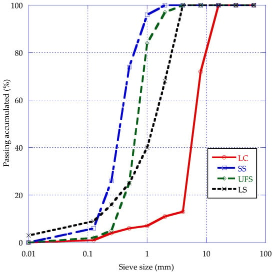
Figure 1.
Grading curves of the aggregates.
2.2. Mix Proportions
For this study, three mixes were designed based on the EFNARC guidelines [22] with the amount of coarse aggregate set at 60% vol. All mixes use the same amount of CEM 52.5 R, effective water and Master Ease 5025 superplasticizer. The same amount of LC is also used but a different amount of three types of sand. The three mixes are described below based on the use of one sand or another:
- A control mix (SCC-C) using only LS and SS adjusted by Fuller’s method.
- A mix that, without using SS, combines UFS with LS (SCC-UFS-100) to obtain an overall particle size distribution as similar as possible to the SCC-C mix. For this purpose, adjustment equations with the granulometric modulus of the sands were proposed.
- A mix that uses half the UFS of the previous mix (SCC-UFS-50) and allows for the use of SS. The proportion of SS and LS is calculated using the adjustment equations with their granulometric modulus.
- The mix proportions are shown in Table 3.
Table 3. Mix proportions (kg/m3).
The proposed procedure for mixing concrete is necessary because of the use of UFS. Its high absorption compared to LS and SS makes the correct homogenization in the mixture of the materials difficult, so to guarantee this, longer mixing and resting times are proposed. The fabrication procedure of the three SCC mixes is described below (Figure 2):
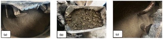
Figure 2.
Mix procedure: dry mix of the aggregates (a); addition of first part of mixing water (b); settling of the SCC mix by 3 min (c).
- Determine the moisture content of aggregates.
- Weigh the aggregates, and moisten the concrete mixer beforehand.
- Add the aggregates from the largest to smallest and add the cement and powder material.
- Mix all the materials for 3 min.
- Add half of the mixing water without superplasticizer (this addition will not take longer than 20 s) and mix for 3 min.
- Add the second part of the water with the superplasticizer and mix for 3 min.
- Stop the concrete mixer and allow the concrete to settle for 3 min.
- Finally, start the concrete mixer and mix the concrete for a further 5 min.
2.3. Fresh State Properties
In order to characterize this concrete, the slump flow test and t500 were determined following the methodology of the EN-12350-8 standard [35]. This standard describes the method to evaluate the flow capacity and stability of the concrete to be obtained.
V-funnel tests were performed according to the EN-12350-9 standard [36] in order to determine the viscosity and filling capacity of self-compacting concrete. L-box tests were performed according to the EN-12350-10 [37] standard using 3 bars to evaluate how SCC flow through narrow openings such as spaces between reinforcing bars.
Finally, the Japanese ring test was performed according to the EN-12350-12 standard [38] to determine the throughput capacity.
Table 4 shows EN-260-1 [39] and EFNARC guidelines [22] range of results of the self-compacting concretes’ fresh state properties.
Table 4.
EN and EFNARC guidelines.
2.4. Mechanical Properties
Cubic specimens of the 100 mm side were produced according to EN-12390-2 [40]. The compressive strength of the specimens was tested at 7 and 28 days of curing according to EN-12390-3 [41] with a SUZPECAR servo hydraulic machine of 1500 kN capacity at the 0.5 MPa/s load rate. Splitting tensile strength EN-12390-6 [42] was performed on three thirds of standard cylindrical specimens of 150 × 300 mm at 28 days with a SUZPECAR servo hydraulic machine of 1500 kN capacity at a 0.05 MPa/s load rate.
2.5. Concrete Microstructure
Concrete structural analysis was carried out with a Zeiss EVO MA15 scanning electron microscope. Micrographs were obtained at different magnifications of the paste-aggregate interface to compare the microstructure of each proposed blend.
The samples analyzed in the SEM were obtained from the inside center of the specimens tested at 28 days compressive strength. For this, it was necessary to extract appropriately sized fragments from each mixture and introduce them into the chamber of the device. When selecting samples, care was taken to ensure that they contained at least one coarse aggregate piece.
Before loading the samples into the SEM, they were gold-plated to obtain images at high magnification and good resolution. To compare the microstructure of the three mixes analyzed, micrographs of the slurry in contact with the coarse aggregate were taken at 1500, 3000 and 7000 magnifications.
3. Results and Discussion
3.1. Fresh State Properties
The results of the fresh state properties tests can be seen in Table 5. The replacement of natural sands by UFS resulted in an improvement in the slump flow, as can be seen in Figure 3. The SCC-C (a) presented a slump flow of 500 mm, the SCC-UFS-50 (b) a slump flow of 730 mm, while SCC-UFS-100 (c) resulted in a slump flow of 750 mm, improving the fluidity by 46% and 50%, respectively, both corresponding to a SF2 category according to EN-206-1 [39]. This is because LS and SS have more fines than UFS, resulting in a higher absorption of water, thus decreasing the SF value. Siddique and Sandhu [28] also reported an increase in the slump flow when up to 15% replacement of UFS was used.
Table 5.
Fresh state properties of the self-compacting concretes.
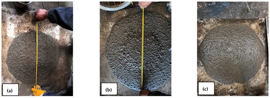
Figure 3.
Appearance of the slump flow of the three self-compacting mixes; SCC-C (a), SCC-UFS-50 (b) and SCC-UFS-100 (c).
Regarding viscosity, Figure 4 shows that the t500 test of SCC-C obtained a time of 5 s to reach the 500 mm mark, which classifies it as in class VS2 according to EN-206-1. It is observed that the incorporation of UFS decreased the time in which the SCC reached the 500 mm mark; SCC-UFS-50 achieved a time reduction of 80% (1 s), while SCC-UFS-100 reduced the time by 60% (2 s). These two SCC are catalogued in class VS1 according to EN-206-1. It is observed that there may be a relationship between the analyzed parameters, so a fitting formula between the t500 and the v-funnel is performed. The equation analyzing the correlation between the v-funnel test and t500 shows an R2 result of 0.99, thus concluding a relationship between these parameters. The variation between the V-funnel time and the t500 is higher with respect to the lower percentage of replacement. This is more evident in the SCC-C, which has the longest throughput times. The improvement in the t500 test result can be attributed to the fact that UFS does not have as many fines as LS and SS, resulting in a less viscous paste.
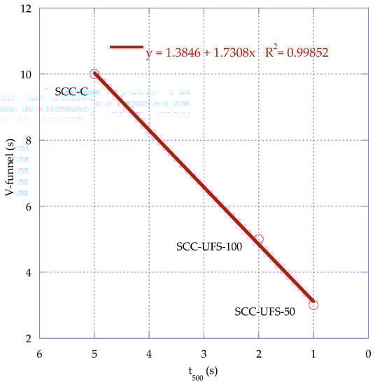
Figure 4.
Time reduction of t500 test and V-funnel test.
Figure 4 also shows the results of the V-funnel test. It can be observed that partial and total replacement of UFS results in a decrease in the passing times. A reduction of 70% and 50% was found, respectively. The reduction in V-funnel passage times and t500 is due to the improved fresh state properties of UFS concretes, which is reflected in the slump diameter. This is because this by-product has less fines than natural sands, leading to a higher flowability of the paste. This is more evident in the SCC-UFS-50, where the V-funnel times and t500 decrease significantly compared to the SCC-C. From Figure 4, it can also be observed that there is a relationship between the V-funnel test and the t500 test, which means that from the result of the t500 test, the V-funnel results can be predicted. According to the research presented by Martins et al. [43] where UFS from the automotive industry was used, this is because UFS has sub-angular-to-round-shaped particles, which improves the fluidity of the SCC. Siddique and Sandhu [28] also reported a decrease in V-funnel time of 10% with the incorporation of up to 15% of UFS.
The t500 time of the SCC-UFS-50 and SCC-UFS-100 was reduced by 60% and 80%, respectively, compared to the SCC-C. Regarding the V-funnel, the SCC-UFS-100 and SCC-UFS-50 presented a decrease in time of 50% and 70% compared to SCC-C. The results presented are in line with the work by Sandhu and Siddique [6], where it is reported that UFS can be incorporated into SCC, while fulfilling EFNARC standards. Şahmaran et al. [32] reported V-funnel time with 100% of UFS similar to those found in this research.
For the Japanese ring test, the SCC-C reached the limit value of 10 mm, whereas SCC-UFS-50 and SCC-UFS-100 were above this limit.
L-box test results show that SCC-C does not have an adequate passing capacity, which could be due to the volume of LC used and to LS and SS having more fines than UFS, creating more friction between the aggregates. On the contrary, SCC-UFS-50 and SCC-UFS-100 fulfil the standard requirement. Similar results with the incorporation of UFS were reported by Sandhu and Siddique [6].
3.2. Mechanical Properties
Figure 5 shows the results of the compressive strength of the three self-compacting concretes at 7 and 28 days of age. SCC-C attained a compressive strength of 21.91 MPa after 7 days, while SCC-UFS-100 and SCC-UFS-50 attained 28.94 MPa and 36.61 MPa, respectively. Compared to SCC-C, SCC-UFS-100 obtained a 32% increase in compressive strength, while the SCC-UFS-50 presented an increase of 67%. At 28 days age, SCC-C presented a compressive strength of 35.92 MPa, while SCC-UFS-100 and SCC-UFS-50 attained a compressive strength of 41.25 and 41.76 MPa, resulting in an increase of 15% and 16%, respectively. In general, it is observed that at early ages, SCC-UFS-100 and SCC-UFS-50 have higher compressive strength than SCC-C, with SCC-UFS-50 displaying the highest strength. However, at 28 days the difference between SCC-UFS-100 and SCC-UFS-50 is minimal. The graphical representation of the development of the SCC strength over time can be represented by means of a logarithmic adjustment as reported by other authors [24,27]. From the equations shown in Figure 5, it is shown that the correlation of R2 analyzing the evolution of compressive strength as a function of time is close to 1; therefore, the fit is adequate to observe the strength of the concretes at different ages, allowing a curve fit in which it is observed that the behavior of SCC-UFS-50 has a higher strength than the other two concretes. The compressive strength differences between the materials studied could be explained by SCC-C fresh state properties being lower than the other two concretes, leading to poor self-compaction and creating voids within the concrete matrix, resulting in a lower compressive strength.
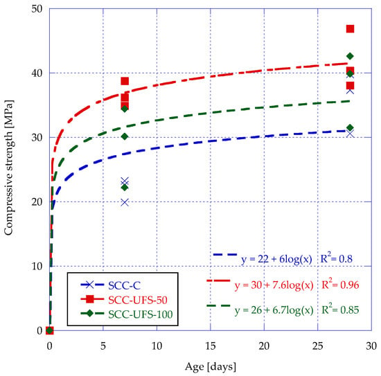
Figure 5.
Compressive strength of the SCC mixes.
Comparing the SCC-UFS-50 with the results of the Sua-iam et al. [44] study in which 50% UFS replacement was incorporated along with a rice husk ash cement substitution (0–20%), the compressive strength was higher at all ages.
The compressive strength results match the findings reported by Ashish and Verma [30], where it was observed that with the increase in up to 50% of UFS replacement, the compressive strength increased as well. This was attributed to the high silica content of UFS, thus creating a denser matrix [30].
Figure 6 shows the appearance of compression cracks at 28 days for SCC-C, SCC-UFS-50 and SCC-UFS-100. The breakage of the SCC-UFS-50 and SCC-UFS-100 specimens was more satisfactory than that of the SCC-C specimens, which is due to the fact that the applied force propagated through the paste-aggregate interface as stated by Sosa et al. [18], resulting in the observed fracture planes.
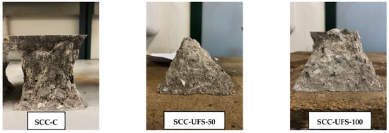
Figure 6.
Detail of compression fractures at 28 days.
As for splitting tensile strength, Figure 7 shows that there is a decrease of 2.8% between SCC-C (2.15 MPa) and SCC-UFS-50 (2.09 MPa). On the other hand, SCC-UFS-100 shows a decrease of 28% (1.53 MPa) compared to SCC-C and a decrease of 26% compared to the SCC-UFS-50. Additionally, the calculation of the standard deviation of the data obtained was performed, resulting in a standard deviation of 0.06 for the SCC-C and 0.07 for both SCC-UFS-50 and SCC-UFS-100.
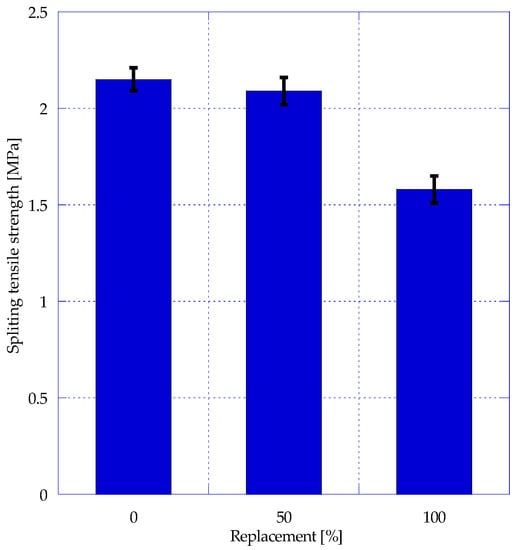
Figure 7.
Splitting tensile strength of the SCC mixes.
In general, it is observed that there is no significant difference between SCC-C and SCC-UFS-50. Similar results were reported by Sandhu and Siddique [6], where it was observed that the incorporation of up to 30% of UFS in self-compacting concrete slightly reduced the splitting tensile strength. Parashar et al. [29] reported that the splitting tensile strength is not affected with the incorporation of up to 40% UFS compared to the control concrete.
3.3. Concrete Microstructure
The microstructural analysis of the concrete at 1500× magnification is presented in Figure 8. It is observed that the SCC-C presents a less compacted and more porous structure than the other two concrete types. This could be related to the lower fresh state properties, where SCC-C presented a lower slump flow and higher t500 time compared to the other concretes. On the other hand, the SCC-UFS-100 showed a more compacted and less porous structure compared to the control concrete, which could also be related to the fresh state properties improvement enhancing concrete compaction. Smazewski [45] concluded that the bond between the aggregates and paste of concrete with UFS affects the concrete strength. Sosa et al. [23] reported that the SCC strength is due to the closed microstructure of the matrix. Moreover, Sandhu and Siddique [6] concluded that a denser microstructure of SCC improves the compressive strength.
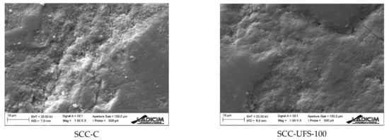
Figure 8.
Micrographs obtained at 1500×.
Figure 9 shows magnifications at 3000× and 7000× comparing SCC-C and SCC-UFS-100. It is observed that SCC-C has a less compact matrix than SCC-UFS-100, which explains why the compressive strength is lower than concrete with UFS. The lack of compaction of the SCC-C increases the porosity of the concrete, so a decrease in the mechanical properties would be expected. This picture confirms the above-mentioned relation of low fresh state properties and lower compressive strength of SCC-C compared to self-compacting concretes containing UFS.
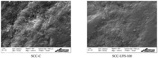
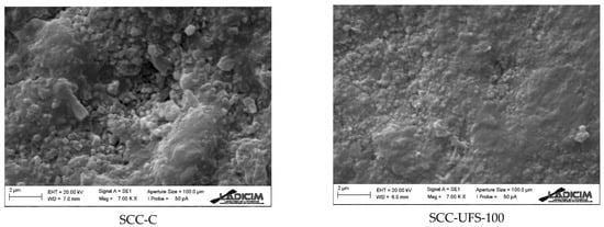
Figure 9.
Micrographs obtained at 3000× and 7000×.
4. Conclusions
In this research, the fresh state properties, mechanical properties and microstructure of self-compacting concrete made with UFS as partial and total replacement for natural fine aggregates was studied. After analyzing the results, the following conclusions can be drawn:
- The partial and total replacement of natural fine aggregates by UFS resulted in an increase in the diameter of the SF, by 46% and 50%, respectively, and in a decrease in t500 and V-funnel times by 60% and 80%, respectively, which is due to the lack of fines in UFS compared to natural sand, resulting in a decrease in the friction between the aggregates and the cement paste.
- There is a strong relationship between the t500 test and V-funnel test, which will help in predicting the results of the V-funnel test based on the t500 test. L-box results improve with the partial and total replacement of UFS compared to the control concrete.
- It is observed that at early ages, SCC-UFS-100 and SCC-UFS-50 have higher compressive strength than SCC-C, with SCC-UFS-50 being the one that presents the highest strength at 7 and 28 days, which is due to the lower compaction capacity of SCC-C, resulting in a less resistant material.
- Splitting tensile strength results showed that there is no great difference between SCC-C and SCC-UFS-50, but SCC-UFS-100 shows a decrease of 27%.
- SEM images proved that the incorporation of UFS enhances the concrete, creating a denser and less porous material compared to the control mix. This explains the higher compressive strength of concrete with UFS.
- In general, the partial and total incorporation of UFS in self-compacting concrete resulted in improved fresh state properties and mechanical properties. Self-compacting concrete with 50%vol. showed better mechanical properties and adequate fresh state properties. Likewise, the findings in this study show that total UFS replacement achieves an improvement in the fresh state properties and mechanical properties compared to control concrete, making this by-product a sustainable alternative to the use of natural fine aggregates.
- For the construction industry, the concretes developed in this research have been classified as SF2 and VS1, so they can be used in elements such as walls, columns, tunnel linings, foundation slabs and pavements. In addition, the use of a raw material, in this case natural sand, could be reduced to a lesser proportion.
- For the foundry industry, the use of its by-product creates a solution to avoid landfill contamination and monetary savings by avoiding paying for the deposit to landfill.
- Future studies could be carried out to analyze the durability of these concretes, with water penetration, oxygen permeability and carbonation being of particular interest.
Author Contributions
Conceptualization, G.G.D.A. and C.T.; methodology, G.G.D.A. and J.A.S.-A.; software, P.T.; validation, J.A.S.-A., C.T. and R.C.; formal analysis, C.T., G.G.D.A. and J.A.S.-A.; investigation, G.G.D.A. and A.A.; resources, C.T.; data curation, G.G.D.A. and P.T; writing—original draft preparation, G.G.D.A., J.A.S.-A. and P.T.; writing—review and editing, P.T., C.T. and A.A.; visualization, C.T. and R.C.; supervision, C.T. and R.C.; project administration, C.T. All authors have read and agreed to the published version of the manuscript.
Funding
This research received no external funding.
Institutional Review Board Statement
Not applicable.
Informed Consent Statement
Not applicable.
Data Availability Statement
Not applicable.
Acknowledgments
The authors would like to thank Reinosa Forgings & Castings for the foundry sand used in this study and the Mexican National Council of Science and Technology (CONACYT) for the support granted during the realization of this work.
Conflicts of Interest
The authors declare no conflict of interest.
References
- Siddique, R.; Kunal; Mehta, A. Utilization of Industrial By-Products and Natural Ashes in Mortar and Concrete Development of Sustainable Construction Materials. In Nonconventional and Vernacular Construction Materials: Characterisation, Properties and Applications; Elsevier Ltd.: Amsterdam, The Netherlands, 2019; pp. 247–303. ISBN 9780081027042. [Google Scholar]
- Del Angel, G.G.; Thomas, C. The Use of Foundry Sand for Recycled Aggregate Concrete. In The Structural Integrity of Recycled Aggregate Concrete Produced with Fillers and Pozzolans; Woodhead Publishing: Cambridge, UK, 2022; pp. 3–24. [Google Scholar] [CrossRef]
- Thiruvenkitam, M.; Pandian, S.; Santra, M.; Subramanian, D. Use of Waste Foundry Sand as a Partial Replacement to Produce Green Concrete: Mechanical Properties, Durability Attributes and Its Economical Assessment. Environ. Technol. Innov. 2020, 19, 101022. [Google Scholar] [CrossRef]
- Guney, Y.; Sari, Y.D.; Yalcin, M.; Tuncan, A.; Donmez, S. Re-Usage of Waste Foundry Sand in High-Strength Concrete. Waste Manag. 2010, 30, 1705–1713. [Google Scholar] [CrossRef] [PubMed]
- Gupta, N.; Siddique, R.; Belarbi, R. Sustainable and Greener Self-Compacting Concrete Incorporating Industrial By-Products: A Review. J. Clean. Prod. 2020, 284, 124803. [Google Scholar] [CrossRef]
- Sandhu, R.K.; Siddique, R. Strength Properties and Microstructural Analysis of Self-Compacting Concrete Incorporating Waste Foundry Sand. Constr. Build. Mater. 2019, 225, 371–383. [Google Scholar] [CrossRef]
- Dyer, P.P.O.L.; Gutierrez Klinsky, L.M.; Silva, S.A.; e Silva, R.A.; de Lima, M.G. Macro and Microstructural Characterisation of Waste Foundry Sand Reused as Aggregate. Road Mater. Pavement Des. 2021, 22, 464–477. [Google Scholar] [CrossRef]
- Zhang, Y.; Sappinen, T.; Korkiala-Tanttu, L.; Vilenius, M.; Juuti, E. Investigations into Stabilized Waste Foundry Sand for Applications in Pavement Structures. Resour. Conserv. Recycl. 2021, 170, 105585. [Google Scholar] [CrossRef]
- Dyer, P.P.O.L.; de Lima, M.G.; Klinsky, L.M.G.; Silva, S.A.; Coppio, G.J.L. Environmental Characterization of Foundry Waste Sand (WFS) in Hot Mix Asphalt (HMA) Mixtures. Constr. Build. Mater. 2018, 171, 474–484. [Google Scholar] [CrossRef]
- Del Angel, G.G.; Aghajanian, A.; Tamayo, P.; Rico, J.; Thomas, C. Siderurgical Aggregate Cement-Treated Bases and Concrete Using Foundry Sand. Appl. Sci. 2021, 11, 435. [Google Scholar] [CrossRef]
- Çevik, S.; Mutuk, T.; Oktay, B.M.; Demirbaş, A.K. Mechanical and Microstructural Characterization of Cement Mortars Prepared by Waste Foundry Sand (WFS). J. Aust. Ceram. Soc. 2017, 53, 829–837. [Google Scholar] [CrossRef]
- Monosi, S.; Sani, D.; Tittarelli, F. Used Foundry Sand in Cement Mortars and Concrete Production. Open Waste Manag. J. 2010, 3, 18–25. [Google Scholar] [CrossRef]
- de Paiva, F.F.G.; Tamashiro, J.R.; Pereira Silva, L.H.; Kinoshita, A. Utilization of Inorganic Solid Wastes in Cementitious Materials—A Systematic Literature Review. Constr. Build. Mater. 2021, 285, 122833. [Google Scholar] [CrossRef]
- Vázquez-Rodriguez, F.J.; Valadez-Ramos, J.; Puente-Ornelas, R.; Contreras, J.E.; Arato, A.; Rodríguez, E.A. Nonferrous Waste Foundry Sand and Milling Fly Ash as Alternative Low Mechanical Strength Materials for Construction Industry: Effect on Mortars at Early Ages. Rev. Rom. Mater. Rom. J. Mater. 2018, 48, 338–345. [Google Scholar]
- Hossiney, N.; Das, P.; Mohan, M.K.; George, J. In-Plant Production of Bricks Containing Waste Foundry Sand—A Study with Belgaum Foundry Industry. Case Stud. Constr. Mater. 2018, 9, e00170. [Google Scholar] [CrossRef]
- Jitendra, K.; Khed, V.C. Optimization of Concrete Blocks with High Volume Fly Ash and Foundry Sand. Mater. Today Proc. 2020, 27, 1172–1179. [Google Scholar] [CrossRef]
- de Matos, P.R.; Marcon, M.F.; Schankoski, R.A.; Prudêncio, L.R. Novel Applications of Waste Foundry Sand in Conventional and Dry-Mix Concretes. J. Environ. Manag. 2019, 244, 294–303. [Google Scholar] [CrossRef]
- Alonso-Santurde, R.; Andrés, A.; Viguri, J.R.; Raimondo, M.; Guarini, G.; Zanelli, C.; Dondi, M. Technological Behaviour and Recycling Potential of Spent Foundry Sands in Clay Bricks. J. Environ. Manag. 2011, 92, 994–1002. [Google Scholar] [CrossRef]
- Ahmad, J.; Aslam, F.; Zaid, O.; Alyousef, R.; Alabduljabbar, H. Mechanical and Durability Characteristics of Sustainable Concrete Modified with Partial Substitution of Waste Foundry Sand. Struct. Concr. 2021, 22, 2775–2790. [Google Scholar] [CrossRef]
- Bilal, H.; Yaqub, M.; Ur Rehman, S.K.; Abid, M.; Alyousef, R.; Alabduljabbar, H.; Aslam, F. Performance of Foundry Sand Concrete under Ambient and Elevated Temperatures. Materials 2019, 12, 2645. [Google Scholar] [CrossRef]
- Siddique, R.; Singh, G.; Singh, M. Recycle Option for Metallurgical By-Product (Spent Foundry Sand) in Green Concrete for Sustainable Construction. J. Clean. Prod. 2018, 172, 1111–1120. [Google Scholar] [CrossRef]
- EFNARC. The European Guidelines for Self-Compacting Concrete. EFCA: Orlando, FL, USA, 2005; p. 63. [Google Scholar]
- Sosa, I.; Tamayo, P.; Sainz-Aja, J.A.; Thomas, C.; Setién, J.; Polanco, J.A. Durability Aspects in Self-Compacting Siderurgical Aggregate Concrete. J. Build. Eng. 2021, 39, 102268. [Google Scholar] [CrossRef]
- Sosa, I.; Thomas, C.; Polanco, J.A.; Setién, J.; Tamayo, P. High Performance Self-Compacting Concrete with Electric Arc Furnace Slag Aggregate and Cupola Slag Powder. Appl. Sci. 2020, 10, 773. [Google Scholar] [CrossRef]
- Fiol, F.; Thomas, C.; Muñoz, C.; Ortega-López, V.; Manso, J.M. The Influence of Recycled Aggregates from Precast Elements on the Mechanical Properties of Structural Self-Compacting Concrete. Constr. Build. Mater. 2018, 182, 309–323. [Google Scholar] [CrossRef]
- Fiol, F.; Thomas, C.; Manso, J.M.; López, I. Transport Mechanisms as Indicators of the Durability of Precast Recycled Concrete. Constr. Build. Mater. 2020, 269, 121263. [Google Scholar] [CrossRef]
- Sainz-Aja, J.; Carrascal, I.; Polanco, J.A.; Thomas, C.; Sosa, I.; Casado, J.; Diego, S. Self-Compacting Recycled Aggregate Concrete Using out-of-Service Railway Superstructure Wastes. J. Clean. Prod. 2019, 230, 945–955. [Google Scholar] [CrossRef]
- Siddique, R.; Sandhu, R.K. Properties of Self-Compacting Concrete Incorporating Waste Foundry Sand. Leonardo J. Sci. 2013, 23, 105–124. [Google Scholar]
- Parashar, A.; Aggarwal, P.; Saini, B.; Aggarwal, Y.; Bishnoi, S. Study on Performance Enhancement of Self-Compacting Concrete Incorporating Waste Foundry Sand. Constr. Build. Mater. 2020, 251, 118875. [Google Scholar] [CrossRef]
- Ashish, D.K.; Verma, S.K. Robustness of Self-Compacting Concrete Containing Waste Foundry Sand and Metakaolin: A Sustainable Approach. J. Hazard. Mater. 2021, 401, 123329. [Google Scholar] [CrossRef]
- Makul, N. Combined Use of Untreated-Waste Rice Husk Ash and Foundry Sand Waste in High-Performance Self-Consolidating Concrete. Results Mater. 2019, 1, 100014. [Google Scholar] [CrossRef]
- Şahmaran, M.; Lachemi, M.; Erdem, T.K.; Yücel, H.E. Use of Spent Foundry Sand and Fly Ash for the Development of Green Self-Consolidating Concrete. Mater. Struct. Constr. 2011, 44, 1193–1204. [Google Scholar] [CrossRef]
- EN 1097-6; Tests for Mechanical and Physical Properties of Aggregates—Part 6: Determination of Particle Density and Water Absorption. British Standard Institute: London, UK, 2014.
- EN 933-2; Tests for Geometrical Properties of Aggregates. Determination of Particle Size Distribution. Test Sieves, Nominal Size of Apertures. British Standard Institute: London, UK, 1999.
- EN 12350-8; Testing Fresh Concrete—Part 8: Self-Compacting Concrete—Slump-Flow Test. British Standard Institute: London, UK, 2020.
- EN 12350-9:2011; Testing Fresh Concrete—Part 9: Self-Compacting Concrete—V-Funnel Test. British Standard Institute: London, UK, 2011.
- EN 12350-10:2011; Testing Fresh Concrete—Part 10: Self-Compacting Concrete—L Box Test. British Standard Institute: London, UK, 2011.
- EN 12350-12:2011; Testing Fresh Concrete—Part 12: Self-Compacting Concrete—J-Ring Test. British Standard Institute: London, UK, 2011.
- EN 206-1; Concrete—Specification, Performance, Production and Conformity. British Standard Institute: London, UK, 2021.
- EN 12390-2; Testing Hardened Concrete. Part 2: Making and Curing Specimens for Strength Tests. British Standard Institute: London, UK, 2015.
- EN 12390-3; Testing Hardened Concrete—Part 3: Compressive Strength of Test Specimens. British Standard Institute: London, UK, 2011.
- EN 12390-6; Testing Hardened Concrete—Part 6: Tensile Splitting Strength of Test Specimens. British Standard Institute: London, UK, 2010.
- de Barros Martins, M.A.; Barros, R.M.; Silva, G.; dos Santos, I.F.S. Study on Waste Foundry Exhaust Sand, WFES, as a Partial Substitute of Fine Aggregates in Conventional Concrete. Sustain. Cities Soc. 2019, 45, 187–196. [Google Scholar] [CrossRef]
- Sua-iam, G.; Makul, N.; Cheng, S.; Sokrai, P. Workability and Compressive Strength Development of Self-Consolidating Concrete Incorporating Rice Husk Ash and Foundry Sand Waste—A Preliminary Experimental Study. Constr. Build. Mater. 2019, 228, 116813. [Google Scholar] [CrossRef]
- Smarzewski, P. Mechanical Properties of Ultra-High Performance Concrete with Partial Utilization of Waste Foundry Sand. Buildings 2020, 10, 11. [Google Scholar] [CrossRef]


Disclaimer/Publisher’s Note: The statements, opinions and data contained in all publications are solely those of the individual author(s) and contributor(s) and not of MDPI and/or the editor(s). MDPI and/or the editor(s) disclaim responsibility for any injury to people or property resulting from any ideas, methods, instructions or products referred to in the content. |
© 2022 by the authors. Licensee MDPI, Basel, Switzerland. This article is an open access article distributed under the terms and conditions of the Creative Commons Attribution (CC BY) license (https://creativecommons.org/licenses/by/4.0/).