Abstract
The automatic emergency braking (AEB) system of the passenger car is responsible for auxiliary braking judgment and decision-making in an emergency. Due to the inevitable pressure response delay of passenger car pneumatic braking systems, a large number of verification tests should be carried out to propose appropriate strategies and algorithms. To realize the rapid verification of the AEB control algorithm, a verification system integrating software-in-the-loop (SIL) and hardware-in-the-loop (HIL) was proposed for a two-axle passenger car. It can verify the logic feasibility of the control algorithm through SIL testing, and can verify the implementation effect of the control algorithm through HIL testing. The verification system is composed of IPG, dSPACE, and a pneumatic braking bench. Considering the influence of pneumatic braking delay, it is well-matched with the actual vehicle AEB system. The AEB hierarchical control algorithm was verified under three typical test conditions. The results show that the SIL testing results of speed and relative distance are in good agreement with the HIL testing results, and the average relative deviation of relative distance is only 1.7 m. The single test time of the SIL testing is about 228 s, which can meet the requirements of rapid verification of the AEB control algorithm of the passenger car.
1. Introduction
Urban public transportation is the main body of urban passenger transportation in China. In recent years, the number of passenger cars in China has grown steadily [1]. Due to the heavily loaded body of the passenger car, its braking system mostly adopts pneumatic braking, which has led to a long pressure response time. If the braking timing is missed, the braking effect of the passenger car will be weakened, which will eventually lead to traffic accidents. According to statistics, about 70% of China’s traffic accidents are caused by braking failure, insufficient braking force, and late braking. Insufficient braking is one of the main causes of collision accidents [2].
In recent years, automatic emergency braking (AEB) has become one of the key technologies of automobile active safety. The vehicle equipped with AEB can accurately grasp the braking time, actively brake the vehicle under dangerous conditions, and effectively avoid collision accidents [3]. Hu L. et al. [4] analyzed the key parameters of the AEB system and proposed an optimized AEB system, which can reduce the severity of collision accidents and unavailable accidents. Accurately judging the driving scene is the premise for the operation of the AEB system. At present, radar and camera are usually used to perceive the driving scene. Begiovane D.J. et al. [5] developed an alternative circular target for AEB system testing. When the 77 GHz millimeter wave radar system detects the target, its RCS level is the same as the actual cycle. Based on the data of 30 traffic accidents, Choi Y. et al. [6] used a simulation to prove that with the increase in the radar angle in the AEB system, the crash avoidance rate of the vehicle is increased. Xique I.J. et al. [7] described the evaluation method of ADAS system sensors and tested and evaluated the performance of millimeter wave radar, LiDAR, and image sensor on site. Stöckle C. et al. [8] proposed a robust design method for AEB system considering sensor measurement error. Numerical examples showed that the method can provide a reference for the design of optimal AEB decision rules.
The design and application of an excellent AEB control algorithm can greatly improve the performance of the AEB system, thereby improving driving safety. Niu W. [9] designed a Petri net model and controller for vehicles and pedestrians in specific areas, which can avoid collisions between vehicles and pedestrians in the Petri net model. Yang W. et al. [10] proposed a model based on BP neural network and hidden Markov model to identify the intentions of drivers in front of them, and further proposed an effective AEB model. Alsuwian T. et al. [11] proposed a multi-sensor fusion AEB control algorithm and verified the robustness and effectiveness of the AEB system through simulation. Zhang R. et al. [12] designed a multi-objective optimization AEB control strategy. The simulation results showed that the multi-objective optimization AEB control method had better performance than the single AEB algorithm in collision avoidance, driving comfort, and fuel economy. Schratter M. et al. [13] formulated the anti-collision of vehicles and pedestrians as a partially observable Markov decision process (POMDP), and compared the anti-collision performance of POMDP and AEB systems under various combinations through experiments.
Note that many researchers verified the performance of the AEB control algorithm through simulation, as mentioned earlier [4,10,12,13]. In addition, Shin S.G. et al. [14] also evaluated the performance of the proposed adaptive AEB control strategy through simulation to prevent collisions with vehicles following behind. Due to the insufficient accuracy of the simulation, some researchers tested the existing AEB products or verified the developed AEB control algorithms in real vehicles [5,7,9]. Park M.K. et al. [15] used a real vehicle to test the pedestrian target selection algorithm on the test track. The results showed that the proposed AEB algorithm can avoid or mitigate accidents. Song Z. et al. [16] developed a set of pedestrian AEB test equipment according to the C-NCAP test requirement, and used the equipment to evaluate the AEB performance of the test vehicle. However, real vehicle testing is time-consuming and expensive.
The hardware-in-the-loop (HIL) technique can embed the real braking system into the software simulation platform through the I/O interfaces, providing a rapid verification platform for the AEB control algorithm, thus reducing the test cost [17]. Yuan Y. et al. [18] proposed a hydraulic brake-by-wire system, and verified the brake force distribution strategy and regenerative braking control strategy through simulation and HIL testing. Cheng S. et al. [19] tested the proposed lateral stability coordinated collision avoidance control system (LSCACS) through HIL testing, and the results showed that the LSCACS is better than that of the traditional AEB system. Zhang N. et al. [20] proposed an integrated coordinated control method for vehicle AFS and ABS, and proposed a solution method for the control model. A HIL test was carried out for the control method on low-adhesion and off-road roads.
The above researches aimed at HIL verification of braking energy management and braking performance optimization strategies. Based on the research results in ADAS, ACC, and AEB, some researchers used HIL testing to verify the control algorithms. Solmaz S. [21] and Schyr C. [22] designed a steerable chassis dynamometer test bench and tested the lane-keeping assistant, adaptive cruise control, and automatic emergency braking functions of the real vehicle. Wang F. et al. [23] proposed a hierarchical ACC control strategy for the city bus, and the HIL test showed that the control strategy can improve the tracking ability, driving comfort, and energy economy of the city bus. Bours R. et al. [24] proposed an AEB system development method combining road test, indoor laboratory test, HIL testing, and simulation. However, the existing HIL system is mainly aimed at the development of the AEB control algorithm for hydraulic braking vehicles. It cannot be directly applied to passenger cars equipped with a pneumatic braking system.
Due to the time-delay characteristics of pneumatic braking, the verification of the AEB control algorithm should meet the high requirements for rapid response to braking pressure. Therefore, it is urgent to develop a test system to shorten the response time of braking pressure by quickly adjusting the pressure of the pneumatic braking system, to more accurately simulate the emergency braking conditions of real vehicles, and quickly verify the effectiveness of the passenger car AEB control algorithm.
In this paper, our contribution is to establish a rapid verification system for the development and verification of passenger car AEB control algorithm, which has software-in-the-loop (SIL) and HIL test functions. The characteristics of the proposed verification system are analyzed through an AEB hierarchical control strategy case, e.g., the rapidity of the test and the characteristics of SIL and HIL methods. The application scenarios of SIL and HIL methods are summarized.
2. Scheme of Verification System
2.1. Working Mechanism of AEB
The passenger car AEB system can obtain the relative position information between vehicles. If the driver cannot make a braking judgment in time, it will urge the vehicle to brake automatically to avoid collision and ensure the safety of passengers. The working mechanism of the AEB system is shown in Figure 1, where VT refers to the vehicle target and VUT refers to the vehicle under test.
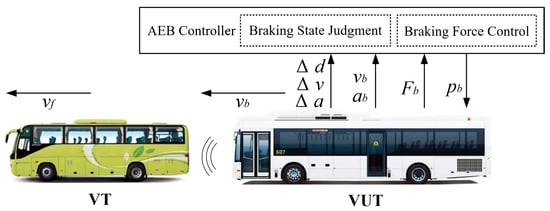
Figure 1.
Schematic diagram of passenger car AEB system.
The AEB system can be divided into three functional layers, namely the perception layer, the decision-making layer, and the execution layer. The perceive layer is mainly composed of millimeter wave radar, a displacement sensor installed on the brake pedal axis, and a steering wheel angle sensor. They are connected to perceive environmental information and driver status, and send the braking command to activate the actuator on the execution layer. The electronic pressure regulating valves as the actuator receive the signal from the controller and then generate corresponding braking pressure. Finally, accurate braking torque will be formed and applied to the corresponding wheels of the passenger car.
2.2. Verification System Demands Analysis
SIL testing, HIL testing, and real vehicle tests are common methods for the development and verification of AEB control algorithms. The characteristics of these methods are compared, as shown in Table 1.

Table 1.
Comparison of verification methods.
The passenger car AEB control algorithm verification system shall be able to quickly complete the algorithm verification with reliable results. Considering the diversity of the verified control algorithms, the verification process should be as close to the real operating environment as possible, and the verification system should have both SIL testing and HIL testing functions.
The controlled parameters of different AEB algorithms are different, and the perception and matching information required for decision-making are also different. A series of studies on the existing AEB control algorithms were summarized, and the parameters required by the verification system were summarized, as shown in Table 2. Note that the actual parameters in Table 2 were used for HIL testing. Through the interaction of actual parameters, the relationship between the simulation model and physical hardware was established, and the whole process development and verification of the passenger car AEB control algorithm were realized.
Table 2.
Parameters required by the verification system.
2.3. Verification System Scheme
According to the functional requirements and information requirements of the verification system, a system framework for the rapid verification of passenger car AEB control algorithm was proposed as shown in Figure 2.
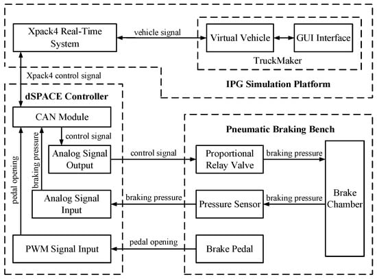
Figure 2.
Verification system structure.
As shown in Figure 2, the verification system is mainly composed of three parts, namely the IPG simulation platform, dSPACE controller, and pneumatic braking bench. The Xpack4 real-time system of the IPG simulation platform provides I/O interfaces for external components. TruckMaker included in the IPG simulation platform is used to establish the dynamic model of the passenger car. It also provides a simulation environment for the operation of virtual vehicles. The M51 board of the Xpack4 real-time system is used to transmit the virtual vehicle and environmental parameters to the dSPACE controller through the CAN bus, which acts as the AEB controller of the passenger car. The braking model built in TruckMaker is replaced by the pneumatic braking bench. The opening signal of the brake pedal and pressure signal of the brake chamber are sent to the dSPACE controller as the real-time braking status information. During the execution of the verification system, the AEB control algorithm can be quickly modified and verified. When the controller makes an emergency braking decision, it will send a control signal to adjust the proportional relay valve of the pneumatic braking bench, and the pressure of the brake chamber will change accordingly. The braking pressure is timely collected by the pressure sensor and then fed back to the dSPACE controller.
3. Verification System Establishment
3.1. Pneumatic Braking Bench
The structure of the passenger car’s pneumatic braking system is shown in Figure 3. The generated braking pressure is related to the opening of the pedal valve. During braking, the proportional relay valve receives the electronic signal, and the pilot solenoid valve generates a corresponding opening degree. Then, the compressed air enters the chamber of the proportional relay valve and generates corresponding braking pressure. As the compressed air in the proportional relay valve is provided by the nearby air tank, and the connecting pipeline is short, it is conducive to reducing the braking delay and obtaining a better automatic emergency braking effect.
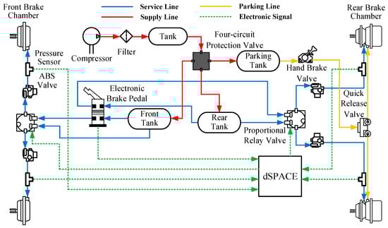
Figure 3.
Structure of passenger car’s pneumatic braking system.
The pneumatic braking bench provides the dSPACE controller with the braking pressure signal and the brake pedal opening signal. The braking pressure is acquired by pressure sensors. The dSPACE controller provides the control signal for the proportional relay valve in the pneumatic braking bench. The pressure sensor, brake pedal, and proportional relay valve are all connected to the interface of the dSPACE controller. The parameters of the main components in the pneumatic braking bench are shown in Table 3.
Table 3.
Components of pneumatic braking bench.
3.2. Pressure Regulating Method of Pneumatic Braking System
The proportional relay valve is the pressure regulator of the pneumatic braking system. The proportional relay valve is controlled by the PWM method, which adjusts the input current by changing the duty cycle, and then adjusting the outlet pressure.
As the hysteresis characteristics of the proportional relay valve will affect the pressure regulation effect of the braking system. The PID method was adopted to control the outlet pressure of the proportional relay valve [25]. The PWM duty cycle was adjusted timely to keep the braking pressure at the target value.
The dynamic pressure regulation performance of the proportional relay valve was verified by the pneumatic braking bench. The target pressure range was set from 0 MPa to 0.7 MPa, while the step size was set as 0.1 MPa by using the ladder lifting mode. The experimental results were shown in Figure 4.
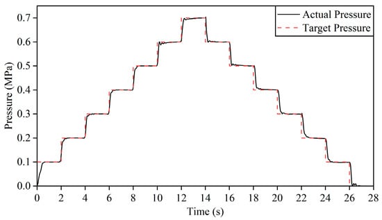
Figure 4.
Dynamic pressure regulation performance of the pneumatic braking system.
As shown in Figure 4, the actual pressure at the outlet of the proportional relay valve can rise and fall according to the target pressure and can reach the target value. The experimental results show that the control algorithm can effectively eliminate the influence of the hysteresis characteristics of the proportional relay valve, and significantly improve the pressure regulation effect of the proportional relay valve. The experiment verified the pressure regulation performance of the pneumatic braking system, and provided a hardware basis for the rapid response of the AEB system.
3.3. Configuration of Passenger Car Simulation Parameters
The structure of the passenger car pneumatic braking system was designed, and its dynamic pressure regulating performance was verified through the pneumatic braking bench. Taking the AEB system of a two-axle passenger car as the test target, TruckMaker was adopted to configure parameters of the virtual vehicle in the verification system, such as mass, tire radius, and inertia of each axle, which is shown in Table 4.
Table 4.
Main parameters of virtual vehicle.
The radar sensor judges the relative position between VUT and VT by sending and receiving pulse signals. When VT enters the radar detection range of VUT, VUT receives the radar signals and automatically identifies the type of detected objects, providing an effective judgment basis for passenger car AEB control. The detection principle of the radar sensor is shown in Figure 5.
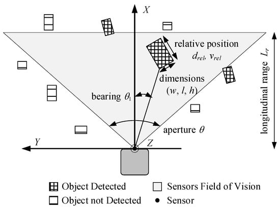
Figure 5.
Schematic diagram of the radar sensor.
When there are obstacles within the detection range of the radar sensor, the obstacles are classified and marked according to the relative distance. The relative distance, relative angle, length, width, and height of obstacles are saved in matrix form. The spatial position of the object detected by the passenger car radar sensor can be expressed as:
where X, Y, and Z are the space coordinate values of objects; drel is the distance between VUT and objects; θ1 is the angle between VUT and objects (bearing); w, l, and h are the width, length, and height of the detected objects, respectively.
When only longitudinal motion is considered, the bearing θ1 is always 0°, which can simplify the object’s spatial position as follows:
The radar sensor is usually mounted at the front of the vehicle. Based on the measuring performance of a certain type of millimeter wave radar, the radar sensor parameters were configured in TruckMaker. In the far range mode, the position (x, y, z) of the sensor was set to (7.8 m, 0 m, 1 m), the field of view (h, v) was set to (9°, 9°), the longitudinal range was set to 200 m, and the update rate was set to 60 Hz. In the near range mode, the field of view (h, v) of the sensor was set to (45°, 45°), the longitudinal range was set to 70 m, and the other parameters were the same as those in the far range mode.
3.4. Implementation of Verification System
The verification system proposed in this paper can realize SIL testing and HIL testing of the AEB control algorithm. This section will describe the implementation process of SIL testing and HIL testing, respectively.
The SIL testing method of the verification system is shown in Figure 6. TruckMaker provides a simulation environment for virtual vehicles, as well as vehicle parameters and environmental parameters for AEB braking decisions. The AEB control algorithm is loaded into the MATLAB/Simulink of the host. TCP/IP protocol is used for information transmission between the host and the IPG simulation platform.
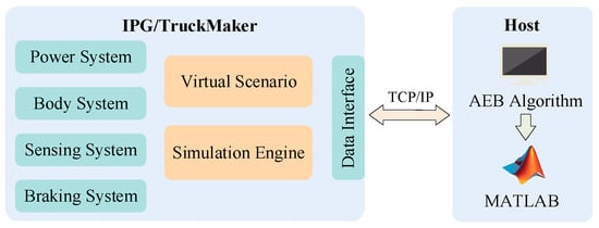
Figure 6.
SIL testing method.
During the SIL testing, the AEB control model of the host makes a decision according to the vehicle parameters and environmental parameters in the simulation process. When TruckMaker receives the decision information, the virtual vehicle presents the corresponding AEB braking status.
The HIL testing method of the verification system is shown in Figure 7. The braking system in TruckMaker is replaced by the pneumatic braking bench. The AEB control algorithm is loaded on Simulink, and real-time code could be downloaded to the dSPACE controller through the RTI interface. The Xpack4 real-time system of the IPG simulation platform provides boards and interfaces for connecting external hardware, and data is transmitted with the dSPACE controller through the CAN bus. The communication between the pneumatic braking bench and the dSPACE controller is carried out through analog signals and digital signals.
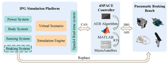
Figure 7.
HIL testing method.
During the HIL testing, the dSPACE controller receives vehicle parameters and environmental parameters through the CAN interface, and receives braking pressure and pedal opening signals through the AIO and DIO interfaces. The current status of the VUT is calculated through the AEB control algorithm. Then the dSPACE controller sends the corresponding proportional relay valve control signal according to the braking decision, receives the braking pressure and pedal opening signals feedback, and transmits the braking pressure signal to the IPG simulation platform. In TruckMaker, braking pressure is converted into braking torque and applied to each wheel. The virtual vehicle presents the corresponding AEB braking status.
The verification system including the IPG simulation platform, dSPACE controller, and pneumatic braking bench is shown in Figure 8.
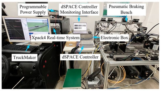
Figure 8.
Verification system.
4. Verification of Passenger Car AEB Control Algorithm
An AEB algorithm verification system for the passenger car was established, which is suitable for the rapid development and verification of the AEB control algorithm. To prove the practicability of the verification system, an AEB hierarchical control algorithm was used as a test example, and virtual AEB test scenarios under various test conditions were established according to the standard. The proposed verification system is used in SIL testing and HIL testing to verify and analyze the AEB hierarchical control algorithm.
4.1. AEB Control Algorithm
The warning model of the AEB control algorithm can be divided into the safety distance model and the time-to-collision (TTC) model [26], which can evaluate the braking safety state base on safety distance and safety time respectively.
The TTC model judges the braking time by comparing the TTC value of the current state with the braking time threshold. When TTC is less than the braking time threshold, a warning message will be sent or automatic emergency braking will be executed. The enhanced TTC model including vehicle acceleration can be described as:
where dr is the relative distance between VUT and VT; vr is the relative speed between VUT and VT; ab is the acceleration of VUT; af is the acceleration of VT; Ts is the set TTC value in safe conditions.
The TTC model considers the motion state of the vehicle before the collision. When VT is stationary and VUT is braking, TTC can be calculated according to the relative distance and relative speed. The TTC algorithm will be switched by comparing the relative acceleration when VT is moving at a constant speed or decelerating. If the speed and acceleration value of VUT is less than or equal to VT, they will not collide, and the TTC value is safe.
The AEB controller judges the braking status based on the TTC value and determines the expected acceleration value of the VUT. When the vehicle is running in good road condition, the maximum achievable braking acceleration is about −8 m/s2 [27]. Considering the comfortableness of automatic emergency braking, the expected acceleration of the AEB system is divided into three levels based on the principle of finite state machine [28], namely −2 m/s2, −4 m/s2, and −6 m/s2.
The AEB system should also be designed with a collision warning function. Considering that a normal driver’s reaction time is about 1 s [29], the warning and braking state can be defined in four stages [11]. The AEB system will switch its working status according to the corresponding TTC value.
- When 4 s ≤ TTC < 3 s, the AEB system enters the brake warning status, and an audible and visual warning signal is issued to remind the driver to brake;
- When 3 s ≤ TTC < 2.25 s, if the driver still fails to brake timely, the AEB system enters the braking status named level I (L I), and the value of braking acceleration is −2 m/s2;
- When 2.25 s ≤ TTC < 1.75 s, the AEB system enters the braking status named level Ⅱ (L Ⅱ), and the value of braking acceleration is −4 m/s2;
- When TTC ≤ 1.75 s, the AEB system enters the braking status named level Ⅲ (L Ⅲ). It will remain in this status until the vehicle is completely stationary, or the TTC value increases and switches to another braking status. The acceleration value of L Ⅲ braking status is −6 m/s2.
The lower controller of the AEB system adopts the PID control strategy to adjust the braking acceleration value, stabilize VUT acceleration at the target acceleration value, and realize error control of AEB acceleration. The PID control algorithm can be expressed as:
where e(t) is the error between the target acceleration value and the actual one at time t; atar(t) is the target acceleration value at time t; abe(t) is the actual acceleration value at time t; Kp, Ki, and Kd is the proportional coefficient, integral constant and differential constant respectively.
The AEB control model built in Simulink is shown in Figure 9. It mainly includes TTC calculation, AEB braking status decision, and PID acceleration control module.
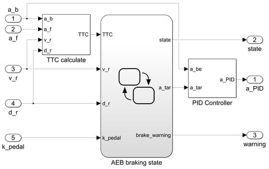
Figure 9.
AEB control algorithm model.
4.2. Typical Test Conditions of AEB
As the main verification platform of the passenger car AEB system, the verification system was built with test scenarios according to typical test conditions of the passenger car AEB system to fully verify the performance of the AEB control algorithm. The AEB test demanded in GB/T 33577–2017 and GB/T 38186–2019 were refined, as shown in Table 5, including three test conditions, i.e., Car-to-Car Rear stationary (CCRs), Car-to-Car Rear moving (CCRm), Car-to-Car Rear braking (CCRb) [30,31].
Table 5.
Passenger car AEB test conditions.
4.3. Test Results of AEB Control Algorithm
4.3.1. CCRs Condition
The parameters of the CCRs condition are set as follows: the relative distance is 120 m, the initial speed of VUT is 80 km/h, and the speed of VT is 0. SIL testing and HIL testing results in the CCRs condition are shown in Figure 10.
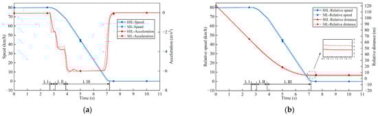
Figure 10.
HIL testing and SIL testing results of CCRs condition: (a) speed of VUT and acceleration of VUT; (b) relative speed and relative distance.
Take the HIL testing curve in Figure 10 as an example, at 2.7 s, the VUT enters the L I braking status. Then, the VUT enters the L Ⅱ and L Ⅲ AEB braking status at 3.1 s and 3.9 s, respectively. At the end of braking at 7.2 s, the speed of VUT decreases to 0. The relative distance is 5.02 m when the VUT stops, the collision between the VUT and the VT is effectively avoided with the AEB control.
4.3.2. CCRm Condition
The parameters of the CCRm condition are set as follows: the relative distance is 120 m, the initial speed of VUT is 80 km/h, and the VT runs at a constant speed of 32 km/h. The HIL testing and SIL testing results in the CCRm condition are shown in Figure 11.
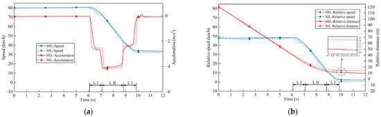
Figure 11.
HIL testing and SIL testing results of CCRm condition: (a) speed of VUT and acceleration of VUT; (b) relative speed and relative distance.
Take the HIL testing curve in Figure 11 as an example, at 6.1 s, the VUT enters the L I AEB braking status. The VUT enters the L Ⅱ AEB braking status at 7.1 s. At 8.8 s, the VUT returns to the L I AEB status. At the end of braking at 9.8 s, the speed of VUT is consistent with that of VT. At the end of AEB braking, the relative distance is 11.19 m, and there is no collision between the VUT and the VT.
4.3.3. CCRb Condition
The parameters of the CCRb condition are set as follows: the relative distance is 30 m, the initial speed of VUT and the initial speed of VT are both 80 km/h, and the VT operates at an acceleration of −3 m/s2. The HIL testing and SIL testing results in the CCRb condition are shown in Figure 12.

Figure 12.
HIL testing and SIL testing results of CCRb condition: (a) speed of VUT and acceleration of VUT; (b) relative speed and relative distance.
Take the HIL testing curve in Figure 12 as an example, the relative speed reaches 24 km/h at 2.3 s, and the VUT starts braking. Then, the TTC value rapidly decreases to below 2.25 s, and the VUT directly enters the L Ⅱ AEB braking status. As the VT continues to decelerate, the collision risk continues to increase, and the VUT enters the L Ⅲ AEB braking status at 3.4 s. At the end of the braking at 7.4 s, the speed of VUT and the speed of VT both decrease to 0. During the braking process, the minimum relative distance is 5.11 m, and there is no collision between the VUT and the VT.
5. Discussion
Based on the proposed verification system, an AEB hierarchical control algorithm was tested. Under the test conditions of CCRs, CCRm, and CCRb, the AEB hierarchical control algorithm can keep the relative distance between the VUT and the VT within a safe range, successfully avoiding vehicle collisions, which proves the effectiveness of the algorithm. However, when the AEB braking of the VUT ends, the relative distance between the VUT and the VT is large, which indicates that the AEB hierarchical control algorithm can be further optimized to avoid AEB triggering prematurely.
The SIL testing results of the AEB hierarchical control algorithm are similar to the HIL testing results, but the specific values are different. The acceleration establishment time is defined as the time when the VUT reaches the target deceleration minus the time when the braking level is switched. The delay time is defined as the HIL acceleration establishment time minus the SIL acceleration establishment time. As shown in Figure 10, Figure 11 and Figure 12, under each test condition, the AEB braking level of the VUT has been switched four times. The delay time of each braking level switching under the CCRs condition is 0.3 s, 0.3 s, 0.1 s, and −0.1 s. The delay time of each braking level switching under the CCRm condition is 0.2 s, 0.2 s, 0.3 s, and 0.3 s. The delay time of each braking level switching under the CCRb condition is 0.1 s, 0 s, 0.2 s, and 0 s. The average time delay of each braking level switching under three test conditions is 0.16 s. The braking delay of HIL testing is mainly caused by the characteristics of the pneumatic braking system, including the mechanical action time and the time of establishing and releasing braking pressure. The existence of braking delay will affect vehicle operation and AEB decision-making.
The relative distance is an important observation parameter to verify the AEB control algorithm, which can be used to evaluate the anti-collision effect and safety margin. Equation (5) is used to evaluate the relative deviation value of the relative distance:
where De is the relative deviation of the relative distance between SIL testing and HIL testing; drs is the relative distance in SIL testing; drh is the relative distance in HIL testing.
Under CCRs and CCRb conditions, the relative deviation of VUT at rest is 1.2 m and 0.6 m, respectively. Under the CCRm condition, when the speed of VUT is consistent with that of VT, the relative deviation is 3.3 m. The average relative deviation under the three test conditions is only 1.7 m, indicating that the SIL testing result is close to the HIL testing result. However, the control and optimization of relative distance should consider the influence of this factor.
When the verification system and test scenarios are established, the time required for SIL testing or HIL testing is defined as a single test time, which is expressed as:
where TA is the single test time; t1 is the establishment time of the data interface; t2 is the parameter adjustment and compilation time; t3 is the simulation time; t4 is the data collection time.
Taking the verification process in Chapter IV as an example, the operations in Equation (6) were repeated 5 times. Typical time values of each stage are shown in Table 6. The data in Table 6 is the sum of the test time of the three test conditions.
Table 6.
Typical values of test time.
Table 6 shows that the single test time for SIL testing of the AEB hierarchical control algorithm is 228 s, and the single test time for HIL testing is 319 s. Note that the single test time does not include the time to verify the system construction and debugging.
Based on the above reasons, we suggest that when the AEB control algorithm needs to be modified repeatedly or the test scenario needs to be updated continuously, SIL testing is preferred. HIL testing is more suitable for AEB control algorithm verification. For example, when relative distance is used as the control parameter, the HIL testing results have higher confidence. If conditions permit, it is recommended to compare and verify SIL testing and HIL testing to improve reliability.
6. Conclusions
In order to quickly verify the AEB control algorithm for passenger cars, the working mechanism of the AEB system and the verification requirements of the AEB control method were analyzed, and a scheme of the AEB verification system for passenger cars was proposed. The dynamic pressure regulation performance of the pneumatic braking system was verified. The passenger car simulation parameters are configured, and the passenger car AEB verification system including the IPG simulation platform, dSPACE controller, and pneumatic braking bench is built. The verification system can provide SIL testing and HIL testing methods for AEB control algorithm verification, and provide a platform for the development of passenger car AEB controllers.
The HIL and SIL comparison tests of the AEB hierarchical control algorithm under typical test conditions verified the effectiveness of the proposed algorithm. In the test results, the SIL curve and the HIL curve have high consistency, and the average relative deviation is only 1.7 m. Without considering the time of building and debugging the verification system, the single test time of SIL testing is 228 s, and the single test time of HIL testing is 319 s. It is recommended to adopt SIL testing when verifying the function of the AEB control algorithm. If there is a higher requirement for accuracy, HIL testing is preferred.
Author Contributions
Conceptualization, J.X.; methodology, L.L. and R.Z.; software, L.L. and F.D.; data curation, L.L., R.Z. and F.D.; writing—original draft preparation, L.L. and R.Z.; writing—review and editing, J.X. and G.L.; visualization, J.X. and L.L.; project administration, G.L.; funding acquisition, J.X. and G.L. All authors have read and agreed to the published version of the manuscript.
Funding
This research was funded by the Key Research and Development Program of Hubei Province of China, grant number YFXM2022000405 and 2022BEC014.
Institutional Review Board Statement
Not applicable.
Informed Consent Statement
Not applicable.
Data Availability Statement
The study did not report any data.
Conflicts of Interest
The authors declare no conflict of interest.
References
- National Bureau of Statistics. China Statistical Yearbook; China Statistics Press: Beijing, China, 2021. [Google Scholar]
- Ren, Y.; Li, J.; Yan, G.; Wang, W.; Liu, X.; Zhang, J. Modeling of the Chinese driver’s braking behavior in the simulated traffic scene of rear-end collision avoidance. IET Conf. Proc. 2011, 92–97. [Google Scholar] [CrossRef]
- Fildes, B.; Keall, M.; Bos, N.; Lie, A.; Page, Y.; Pastor, C.; Pennisi, L.; Rizzi, M.; Thomas, P.; Tingvall, C. Effectiveness of low speed autonomous emergency braking in real-world rear-end crashes. Accid. Anal. Prev. 2015, 81, 24–29. [Google Scholar] [CrossRef] [PubMed]
- Hu, L.; Li, H.; Yi, P.; Huang, J.; Lin, M.; Wang, H. Investigation on AEB Key Parameters for Improving Car to Two-Wheeler Collision Safety Using In-Depth Traffic Accident Data. IEEE Trans. Veh. Technol. 2022, 1–16. [Google Scholar] [CrossRef]
- Belgiovane, D.J.; Chen, C.C.; Chien, S.Y.P.; Sherony, R. Surrogate Bicycle Design for Millimeter-Wave Automotive Radar Pre-Collision Testing. IEEE Trans. Intell. Transp. Syst. 2017, 18, 2413–2422. [Google Scholar] [CrossRef]
- Choi, Y.; Baek, S.; Kim, C.; Yoon, J.; Lee, S.M. Simulation of AEBS Applicability by Changing Radar Detection Angle. Appl. Sci. 2021, 11, 2305. [Google Scholar] [CrossRef]
- Xique, I.J.; Buller, W.; Fard, Z.B.; Dennis, E.; Hart, B. Evaluating Complementary Strengths and Weaknesses of ADAS Sensors. In Proceedings of the 2018 IEEE 88th Vehicular Technology Conference (VTC-Fall), Chicago, IL, USA, 27–30 August 2018; pp. 1–5. [Google Scholar]
- Stöckle, C.; Utschick, W.; Herrmann, S.; Dirndorfer, T. Robust Function and Sensor Design Considering Sensor Measurement Errors Applied to Automatic Emergency Braking. In Proceedings of the 2019 IEEE Intelligent Vehicles Symposium (IV), Paris, France, 9–12 June 2019; pp. 2284–2290. [Google Scholar]
- Niu, W. A Petri Net Based Model for AEB Systems Considering Vehicle and Pedestrian/Cyclist in a Certain Area. Ph.D. Thesis, Purdue University, West Lafayette, IN, USA, 2017. [Google Scholar]
- Yang, W.; Liu, J.; Zhou, K.; Zhang, Z.; Qu, X. An Automatic Emergency Braking Model considering Driver’s Intention Recognition of the Front Vehicle. J. Adv. Transport. 2020, 2020, 5172305. [Google Scholar] [CrossRef]
- Alsuwian, T.; Saeed, R.B.; Amin, A.A. Autonomous Vehicle with Emergency Braking Algorithm Based on Multi-Sensor Fusion and Super Twisting Speed Controller. Appl. Sci. 2022, 12, 8458. [Google Scholar] [CrossRef]
- Zhang, R.; Li, K.; He, Z.; Wang, H.; You, F. Advanced Emergency Braking Control Based on a Nonlinear Model Predictive Algorithm for Intelligent Vehicles. Appl. Sci. 2017, 7, 504. [Google Scholar] [CrossRef]
- Schratter, M.; Bouton, M.; Kochenderfer, M.J.; Watzenig, D. Pedestrian Collision Avoidance System for Scenarios with Occlusions. In Proceedings of the 2019 IEEE Intelligent Vehicles Symposium (IV), Paris, France, 9–12 June 2019; pp. 1054–1060. [Google Scholar]
- Shin, S.G.; Ahn, D.R.; Baek, Y.S.; Lee, H.K. Adaptive AEB Control Strategy for Collision Avoidance Including Rear Vehicles. In Proceedings of the 2019 IEEE Intelligent Transportation Systems Conference (ITSC), Auckland, New Zealand, 27–30 October 2019; pp. 2872–2878. [Google Scholar]
- Park, M.K.; Lee, S.Y.; Kwon, C.K.; Kim, S.W. Design of Pedestrian Target Selection With Funnel Map for Pedestrian AEB System. IEEE Trans. Veh. Technol. 2017, 66, 3597–3609. [Google Scholar] [CrossRef]
- Song, Z.; Cao, L.; Chou, C.C. Development of Test Equipment for Pedestrian-Automatic Emergency Braking Based on C-NCAP (2018). Sensors 2020, 20, 6206. [Google Scholar] [CrossRef] [PubMed]
- Schulze, T.; Stavesand, J.-E. Hardware-in-the-Loop Test Process for Modern E/E Systems. In Proceedings of the Simulation and Testing for Vehicle Technology, Berlin, Germany, 12–13 May 2016; Springer: Cham, Switzerland, 2016; pp. 343–360. [Google Scholar] [CrossRef]
- Yuan, Y.; Zhang, J.; Li, Y.; Lv, C. Regenerative brake-by-wire system development and hardware-in-loop test for autonomous electrified vehicle. In Proceedings of the SAE World Congress Experience, Detroit, MI, USA, 4–6 April 2017. [Google Scholar] [CrossRef]
- Cheng, S.; Li, L.; Guo, H.Q.; Chen, Z.G.; Song, P. Longitudinal Collision Avoidance and Lateral Stability Adaptive Control System Based on MPC of Autonomous Vehicles. IEEE Trans. Intell. Transp. Syst. 2020, 21, 2376–2385. [Google Scholar] [CrossRef]
- Zhang, N.; Wang, J.; Li, Z.; Li, S.; Ding, H. Multi-Agent-Based Coordinated Control of ABS and AFS for Distributed Drive Electric Vehicles. Energies 2022, 15, 1919. [Google Scholar] [CrossRef]
- Solmaz, S.; Holzinger, F. A Novel Testbench for Development, Calibration and Functional Testing of ADAS/AD Functions. In Proceedings of the 2019 IEEE International Conference on Connected Vehicles and Expo (ICCVE), Graz, Austria, 4–8 November 2019; pp. 1–8. [Google Scholar]
- Schyr, C.; Inoue, H.; Nakaoka, Y. Vehicle-in-the-Loop Testing—A Comparative Study for Efficient Validation of ADAS/AD Functions. In Proceedings of the 2022 International Conference on Connected Vehicle and Expo (ICCVE), Lakeland, FL, USA, 7–9 March 2022; pp. 1–8. [Google Scholar]
- Wang, F.; Peng, Q.; Zang, X.; Xue, Q. Adaptive Cruise Control for Intelligent City Bus Based on Vehicle Mass and Road Slope Estimation. Appl. Sci. 2021, 11, 12137. [Google Scholar] [CrossRef]
- Bours, R.; Rauf, K.; Kietlinski, K. A method for developing aeb systems based on integration of virtual and experimental tools. In Proceedings of the 23rd International Technical Conference on the Enhanced Safety of Vehicles (ESV) National Highway Traffic Safety Administration, Yokohama, Japan, 3–6 April 2013. [Google Scholar]
- You, M.; Zhang, J.; Sun, D.; Gou, J. Characteristics analysis and control study of a pneumatic proportional valve. In Proceedings of the 2015 IEEE Advanced Information Technology, Electronic and Automation Control Conference (IAEAC), Chongqing, China, 19–20 December 2015; pp. 242–247. [Google Scholar]
- Chen, Y.L.; Shen, K.Y.; Wang, S.C. Forward collision warning system considering both time-to-collision and safety braking distance. In Proceedings of the 2013 IEEE 8th Conference on Industrial Electronics and Applications (ICIEA), Melbourne, Australia, 19–21 June 2013; pp. 972–977. [Google Scholar]
- Mitschke, M.; Wallentowitz, H. Dynamik der Kraftfahrzeuge; Springer: Berlin/Heidenberg, Germany, 2004. [Google Scholar]
- Zhang, M.; Li, N.; Girard, A.; Kolmanovsky, I. A Finite State Machine Based Automated Driving Controller and its Stochastic Optimization. In Proceedings of the ASME Dynamic Systems and Control Conference, Tysons, VA, USA, 11–13 October 2017; American Society of Mechanical Engineers: New York, NY, USA, 2017; p. V002T007A002. [Google Scholar]
- Makishita, H.; Matsunaga, K. Differences of drivers’ reaction times according to age and mental workload. Accid. Anal. Prev. 2008, 40, 567–575. [Google Scholar] [CrossRef] [PubMed]
- GB/T 33577–2017; Intelligent Transportation Systems-Forward Vehicle Collision Warning Systems-Performance Requirements and Test Procedures. Standards Press of China: Beijing, China, 2017.
- GB/T 38186–2019; Performance Requirements and Test Methods for Advanced Emergency Braking System (AEBS) of Commercial Vehicles. Standards Press of China: Beijing, China, 2019.


Disclaimer/Publisher’s Note: The statements, opinions and data contained in all publications are solely those of the individual author(s) and contributor(s) and not of MDPI and/or the editor(s). MDPI and/or the editor(s) disclaim responsibility for any injury to people or property resulting from any ideas, methods, instructions or products referred to in the content. |
© 2022 by the authors. Licensee MDPI, Basel, Switzerland. This article is an open access article distributed under the terms and conditions of the Creative Commons Attribution (CC BY) license (https://creativecommons.org/licenses/by/4.0/).