Article

Experimental Analysis of the Behaviour of Piled Raft Foundations in Loose Sand

1
Faculty of Civil Engineering in Subotica, University of Novi Sad, Kozaračka 2a, 24000 Subotica, Serbia
2
Faculty of Mechanical and Civil Engineering in Kraljevo, University of Kragujevac, Dositejeva 19, 36000 Kraljevo, Serbia
3
Faculty of Technical Sciences, University of Novi Sad, Trg Dositeja Obradovica 6, 21000 Novi Sad, Serbia
*
Author to whom correspondence should be addressed.
Appl. Sci. 2023, 13(1), 546; https://doi.org/10.3390/app13010546
Submission received: 27 November 2022 / Revised: 11 December 2022 / Accepted: 16 December 2022 / Published: 30 December 2022
(This article belongs to the Section Civil Engineering)

Abstract

:
This paper presents the experimental analysis that was conducted on small-scale 1g physical models of piled raft foundation structures with a group of 2 × 2 piles in loose sand. The purpose of the piles was to reduce the settlement of the raft. The test program included twelve experiments, three of which were conducted on a raft alone and nine on piled rafts at pile distances of 3d, 4d, and 5d and pile lengths of 10d, 20d, and 40d, where d is pile diameter. The test results show that the current conventional approach to design of piled raft foundations, at a high safety load factor in piles that assume to take the whole external applied load, is very conservative. Instead, it is more economical to apply a low bearing capacity factor for piles as settlement reducers and maximize use of raft bearing capacity to carry part of the external load.

1. Introduction

1.1. Foreword

This research is motivated by the practical experience of the authors, that is, the need to reliably evaluate the interaction of the cap and piles that serve as settlement reducers. Namely, during construction of various structures within the coastal area of Danube River in Serbia, on a layer of very loose dredged sand up to 7 m thick, in order to reduce settling, deep foundation on piles is usually foreseen. Due to the relatively large thickness of the natural alluvion deposits near the riverbank, the piles predominantly demonstrated floating behaviour. To achieve a more economical solution, a proposal was made to determine the number of piles on the basis of a very low safety factor in relation to the ultimate load in the order of magnitude 1.2–1.3 to make as much use as possible of the bearing capacity of the caps with a reduction in settling due to the presence of the piles. Due to shortness in time, this idea was abandoned, but an interesting topic remained open, motivating this research, for which the authors of the paper conducted experiments on a small-scale 1g physical model. Bearing in mind that the piles are placed in fine-grained, loose Danube sand, it can be assumed that the shear strength resistance envelope of the sand is a linear function; that is, the angle of shear resistance is constant or independent of effective normal stress. As a result, the scale effects that mainly originate from the curved shear strength envelope, as in compacted sands, can be neglected. Having this in mind, it can be assumed that application of the small-scale 1g physical model as it is presented in this paper for pile bearing capacity estimation in loose sands is justified.

1.2. Introduction

In geotechnical engineering, a shallow foundation structure is not always applicable due to deformability of soil. One of the most significant aspects in foundation design is bearing capacity [1]. Accordingly, alternative foundation structure solutions are used, such as deep foundations. Calculation of the pile group is based on the assumption that the entire load from the aboveground part of the structure is taken over by the piles, without taking into account the load bearing capacity of the raft. This approach to calculation is very conservative; the basic principle of calculation should be based on the fact that the foundation structure contains as many piles as would be required to reduce the settlement to an acceptable level. That way, the load from the aboveground structure is transferred to the ground partly through the raft and partly through piles. This calculation approach aims to contribute to optimization of the foundation structure, thus reducing the number of piles.
The mechanism and design theory considering utilization of soil below the raft to bear a part of the total applied load in piled raft foundation has been a research hotspot for more than half a century [2,3,4]. Assuming that the load is evenly distributed over the area of the raft, a deflection will occur in the middle of it, as schematically shown in Figure 1a. By adding a specific number of piles under the raft, settlement and differential settlement will be reduced (Figure 1b). Basuony El-Garhy et al. [5] have conducted tests with a limited number of piles beneath the central part of the raft, using piles as settlement reducers. Using piles to reduce settlement is an idea that originated earlier, in the 1970s [6]. There are many studies that deal with behaviour of raft foundations and piled raft foundations [7,8,9,10,11,12,13,14,15,16,17,18,19] and settlement of piled raft foundations [20,21,22,23]. In recent research [24,25,26,27,28,29,30,31], the response of piled raft foundations to static and cyclic loading was studied experimentally and numerically. Muhammad Rehan Hakro [32] investigated piled raft foundations in multilayer soil with different stiffness, exposed to different loads, by using software package Plaxis 2D. O. Reul and M. Randolph [33] dealt with the influences of certain parameters on the load distribution between the raft and the piles, such as the number and arrangement of piles, the piles’ length, and the raft stiffness. They concluded that, when using longer piles, there may be less settlement than when using a larger number of piles, and bending moments in the raft cannot be reduced by supporting it with piles. Phung [34] concluded that the conventional practice of designing piled raft foundations is based on the assumption that external load is carried by piles and any raft contribution is neglected. Therefore, this approach is too conservative because the raft can carry a significant part of the load due to direct contact with the ground. Bayad and others [35] concluded that, in tests conducted on piled raft foundations 2 × 2, 3 × 3, and 4 × 4, when the raft settlement is 10 mm, which was the smallest lateral dimension of the raft, 60% of the total load was taken over by the pile group. Each pile group behaves as a raft with piles except those cases in which there is no contact between the raft and the soil [36].
Fleming [37] states that, when designing piled raft foundations, rafts have certain load bearing capacity. Due to not considering the contribution of the load bearing capacity of the raft, when designing piled raft foundations, more piles are required than actually needed [38]. Assel Zhanabayeva et al. [39] compared designs of piled raft foundations by applying Eurocode 7 and Kazakhstan regulations. Thea concluded that Eurocode 7 shows more conservative results, with an increased level of safety [40,41,42]. Since the raft and the piles each contribute to the behaviour of the raft with piles system, the key component for the design is the portion of load carried by each element [36,43]. The piled raft foundation structure is a foundation structure that combines the effective bearing capacity of raft and piles while taking into account different interactions: pile–soil, pile–pile, raft–soil, pile–raft. The interaction between soil and structure has an impact on soil behaviour as well as the behaviour of piles subjected to load [44,45,46]. The behaviour of the pile–soil system is mostly nonlinear. The load in the horizontally loaded pile is resisted by the pile–ground interaction, which also depends on pile diameter and pile material [47]. Bourgeois [48] investigated the influence of the pile–soil interaction in a vertically loaded group of piles. Some previous studies have specified the ratio of load distribution as a function of the geometry of the foundation, stiffness, and compressibility of the soil [49,50,51]. For sandy soils, the pile–raft interaction effect is significant for the overall behaviour of the piled raft system [52,53,54]. Based on experimental results, Phung Duc Long and other [55] authors proposed a simplified method that can be used in design. The experiment shows that, at the beginning of the loading of the piled raft foundation, piles take over most of the load, and, after reaching the bearing capacity of the pile, the load is transferred to the raft. This method can provide effective results if used with the finite element method for estimating settlement of piled raft foundations. Some of the analytical and numerical studies conducted on this topic are described in [56,57,58,59,60,61]; however, experimental studies on piled raft systems are few, while verification of the analytical and numerical results can occur by conducting tests on physical models in the laboratory.
In this paper, the results of experimental analysis of the 1g model of the raft foundations, conducted for the purpose of doctoral thesis research of the first author, were used. The aim of the research was to point out that, when designing these types of foundation structures on loose sand, the load bearing capacity of the raft foundation should not be neglected. This will reduce the number of piles required to receive vertical force and thus lead to more efficient foundation structure design. In addition to raft and piles interaction, pile group effect was also investigated.

2. Materials and Methods

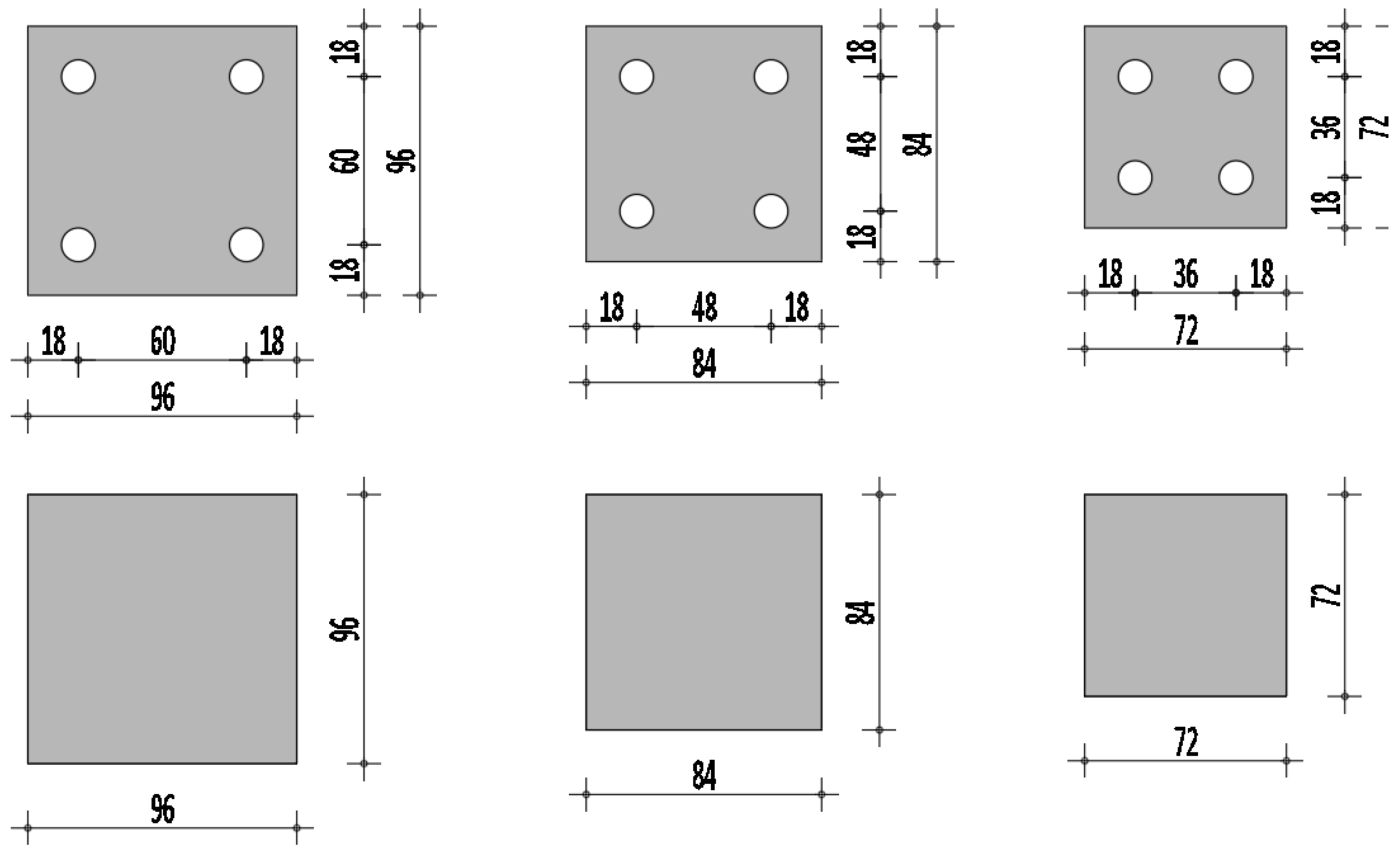
Laboratory tests were performed on a 1g model for a group of four piles, assembled in a 2 × 2 pile configuration. The test program consisted of twelve experiments, three of which were performed on piles of length L = 40d, 20d, 10d, with pile distances of 3d, 4d, 5d, and three experiments with a raft foundation system without piles. Pile arrangement, as well as raft dimensions, are shown in Figure 2.

2.1. Soil Parameters

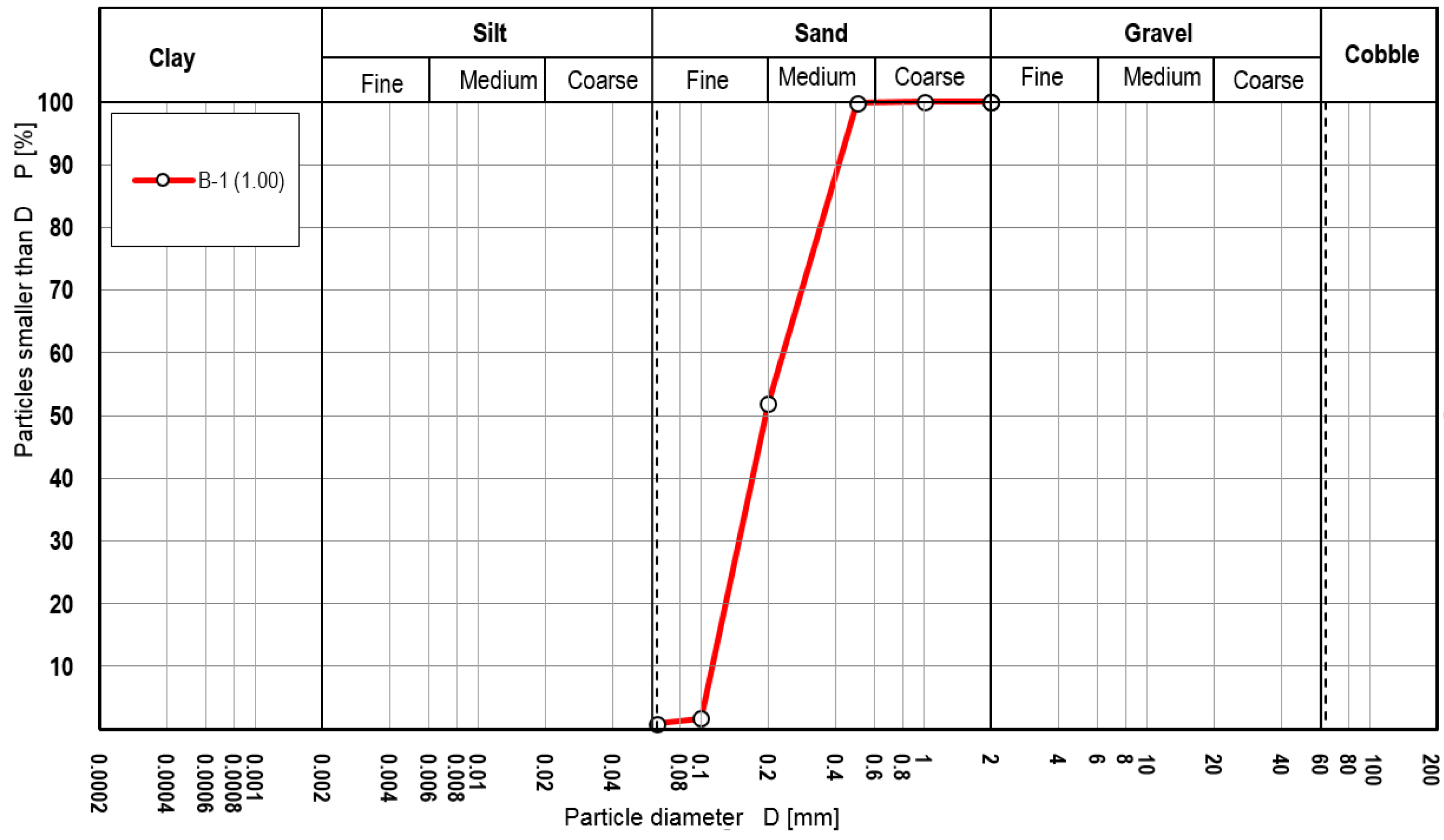
Dry sand was used in the experiment. Granulometric analysis was performed in order to determine the granulometric curve of the soil used. The obtained granulometric curve parameters were: D10 = 0.11 mm, D30 = 0.15 mm, D60 = 0.23 mm, the uniformity coefficient is Cu = 2.1, and the curvature coefficient Cz = 0.8, Figure 3.
Based on the united soil classification (USCS), the tested soil sample is classified as poorly graded SP sand. By direct shear test, it is determined that the angle of internal friction is 30°.
Figure 3. The granulometric curve.
Applsci 13 00546 g003

2.2. Models of Piled Raft Foundations

The experimental model of the piled raft foundation is composed of the square raft and the piles. The raft is made of 10 mm thick steel S 235 plate, which represents an absolutely rigid body that is not susceptible to bending under forces that occur during the experiment.
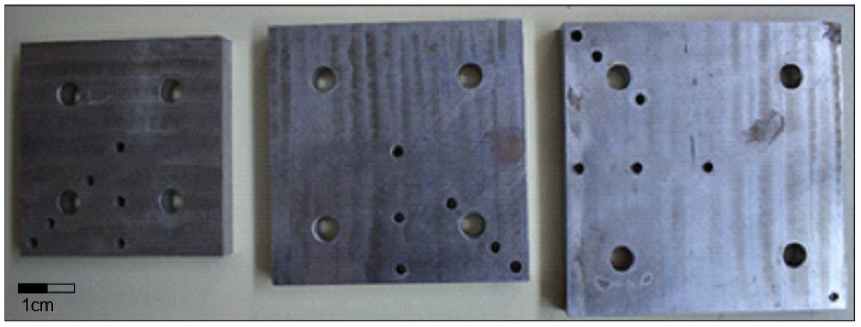
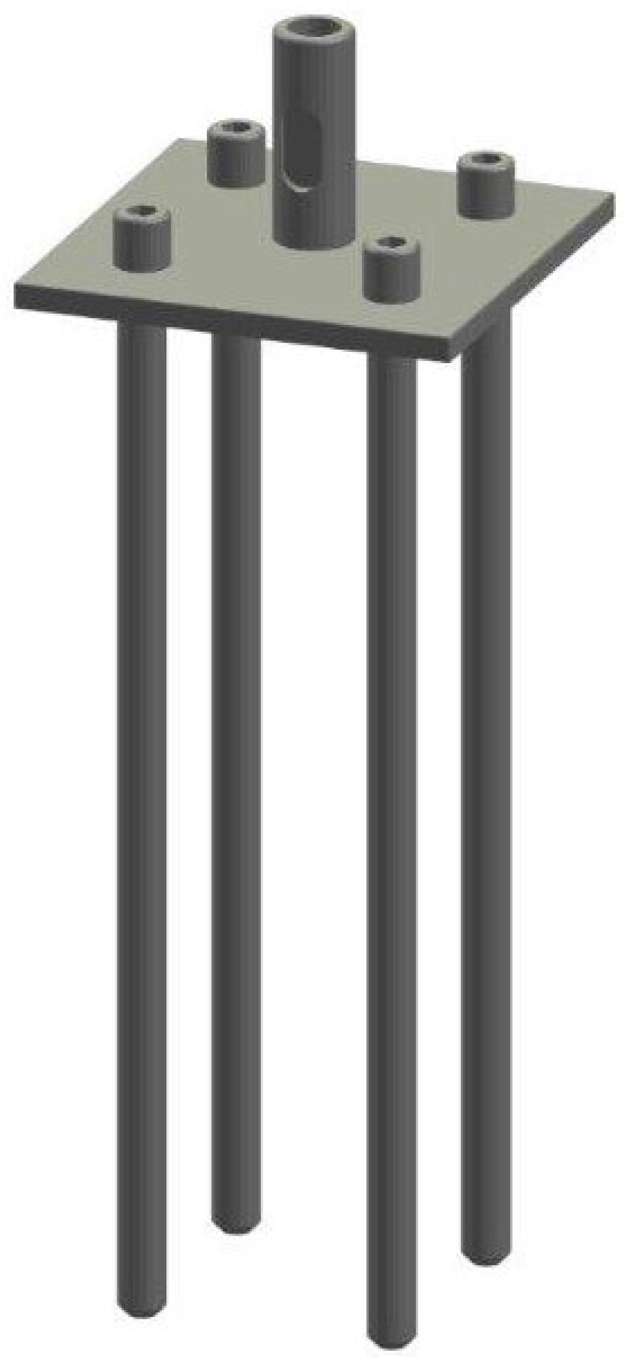
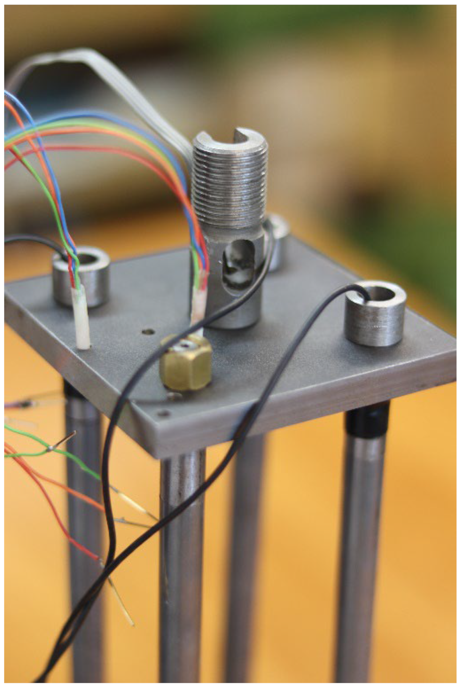
Four 9 mm diameter holes were drilled in the raft, arranged in accordance with the configuration of the piles. Apart from the holes for the piles, additional small holes, 3 mm diameter, were prepared for placement of the miniature pressure sensors. The piles were installed so that their heads were slipped through the 9 mm holes, then the pile is fixed to the raft foundation by means of a thread that is incised at the top of the pile. That way, the piles could be tightened with a nut from the upper surface of the raft foundation, thus achieving a rigid connection between the raft and the piles (Figure 4). Piles are made of steel rods S 235 with a diameter of 12 mm. For easier and simpler installation, they are composed of three parts (Figure 5). Assembled piled raft model is shown in the Figure 6. The base of the pile is conical so that it reduces the base load bearing effects. On the upper section of the pile, an adapter was mounted that creates the connection between the raft and the pile. Within this adapter (Figure 7), the axial force in the pile head is measured with a miniature load cell. Figure 8 shows the actual piled raft model prior to driving it into the soil, while Figure 9 shows the model during its driving into the soil.

2.3. Measuring Instruments and Equipment

2.3.1. Test Box

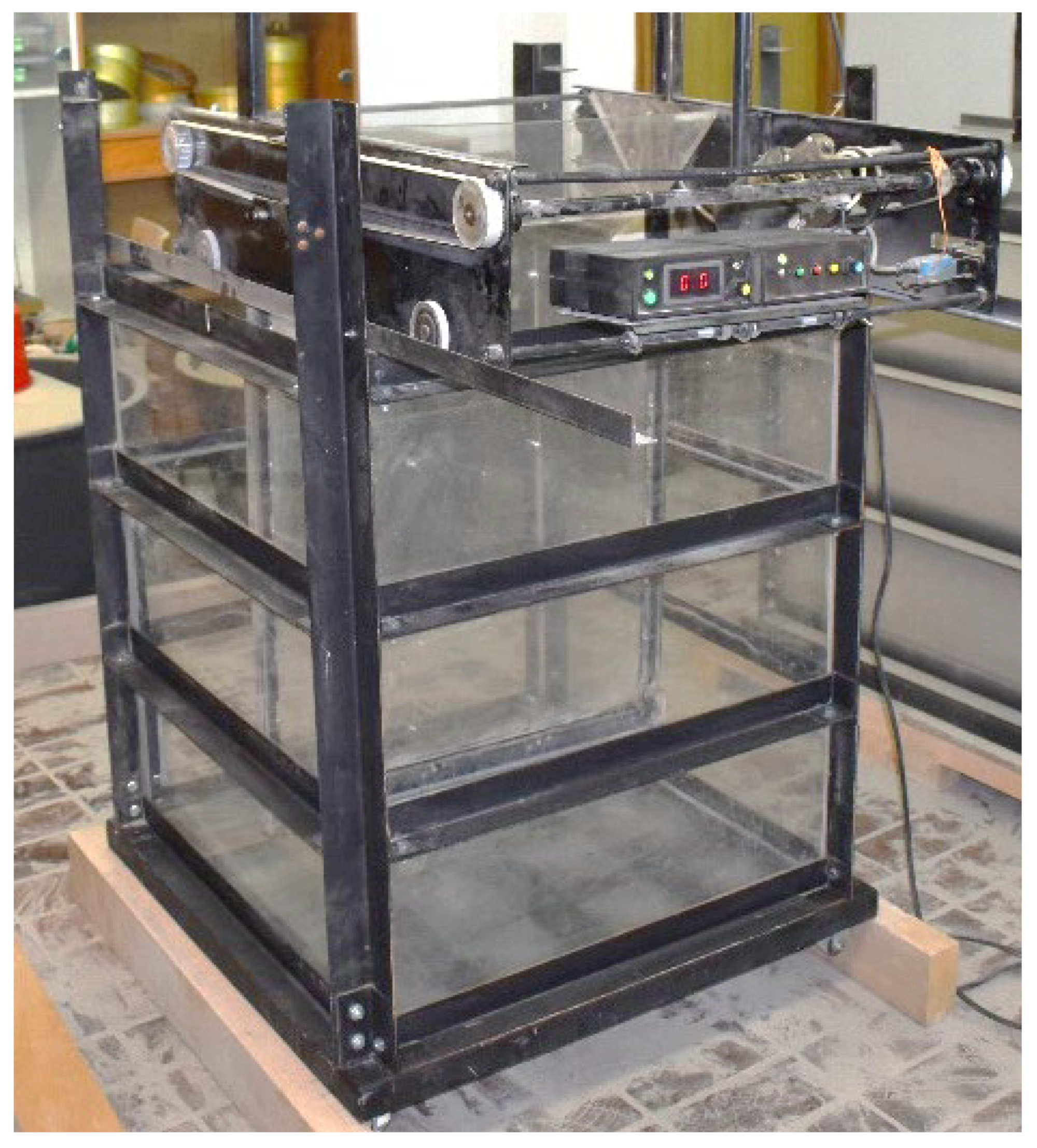
Testing of the models was performed in specially designed mobile test boxes (Figure 10). The boxes, with dimensions of 75 × 75 × 100 cm, were made of steel L profiles, 35 × 35 × 2 mm. The corners are constructed with four columns, which are interconnected by horizontal profiles, welded on every 25 cm along the height of the columns. The profiles form a stable structure without lateral deformations of the box walls. The inside of the box is encased with 3 mm thick Plexiglass to make it easier to determine the height of the filled sand, as well as to eliminate friction between the sand and the walls of the box, as Mosa [62] and others have observed in their experiments.

2.3.2. Data Logger

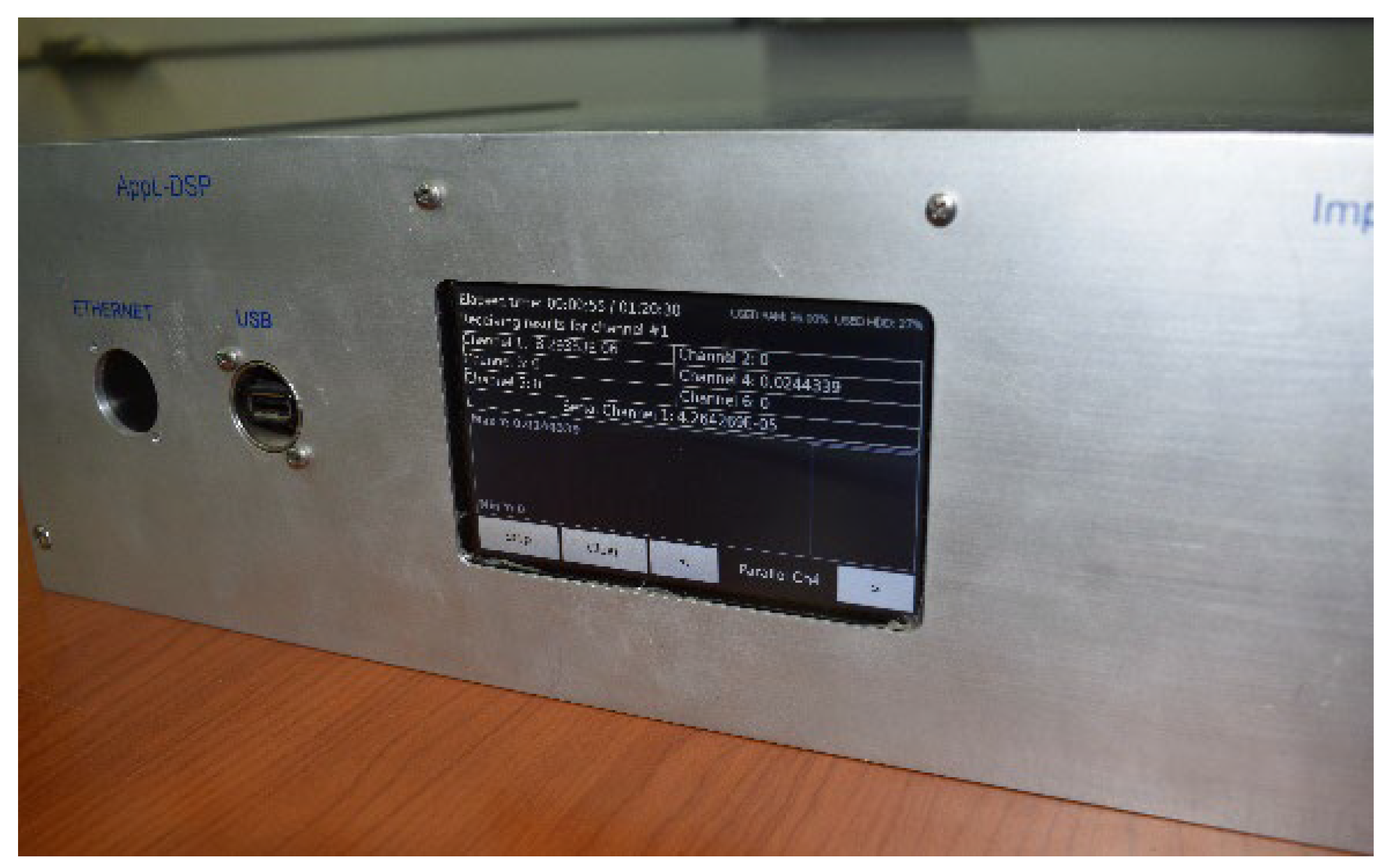
Automatic digital data acquisition was conducted with use of a data logger that has 6 parallel and 64 serial channels (Figure 11).

2.3.3. Digital Callipers

To monitor the displacements of the raft due to load, digital callipers with an accuracy 1/100 mm were used. Three callipers (MIB Messzeuge GMBH, Spangenberg, Germany) with a maximum deflection range of 150 mm were attached to a special frame structure with flexible magnetic stands (Figure 12).

2.3.4. Load Cell

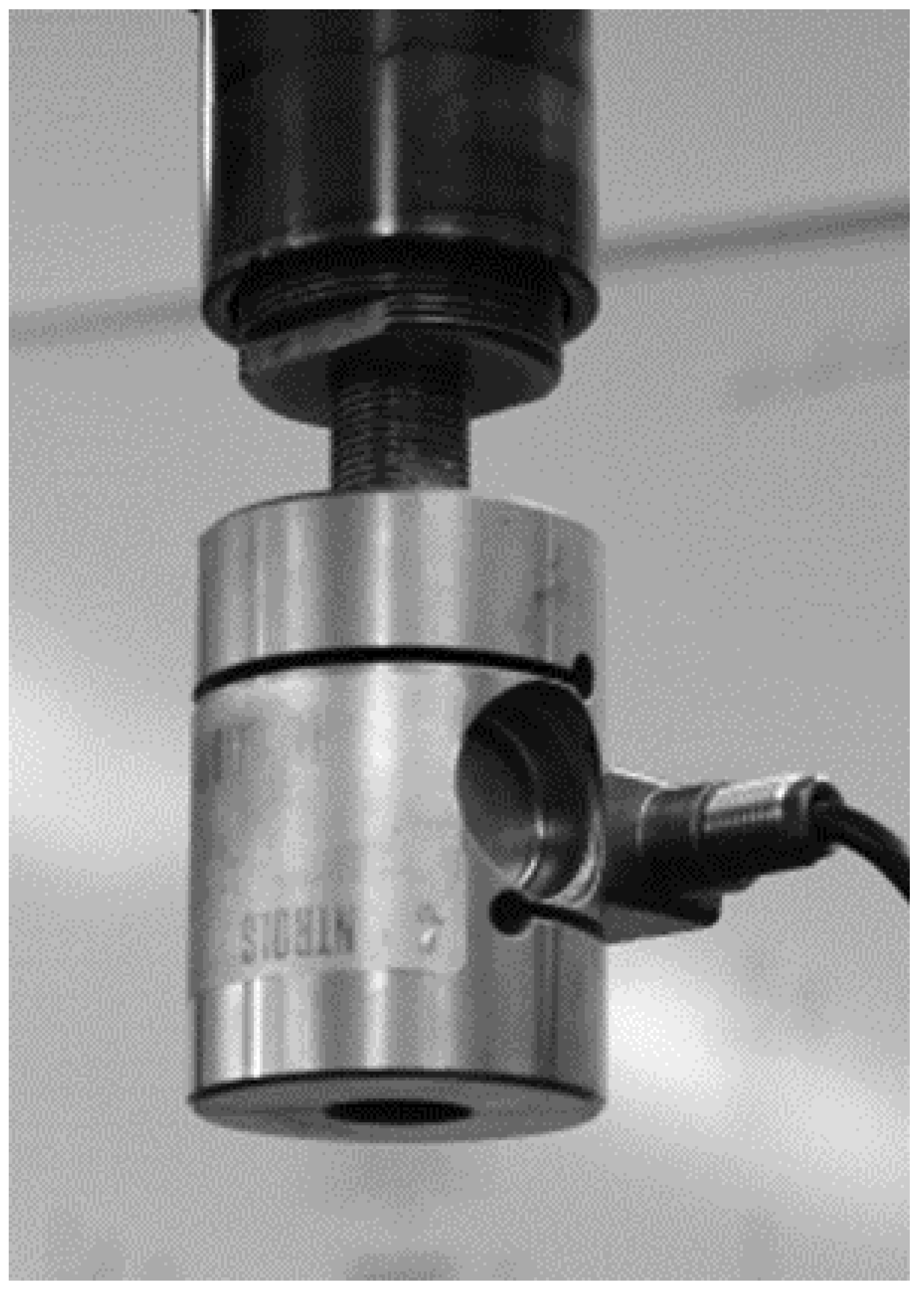
In order to measure the total vertical force acting on the raft foundation model, a load cell with measuring capacity of 350 kg and precision of 0.2% was used (Figure 13). Before commencement of the experiments, the load cell was calibrated with standard weights.

2.3.5. Sensor for Measuring the Force in the Pile

A miniature force sensor DYMH-106, with a total measuring capacity of 30 kg, was used to measure the force in the individual pile (Figure 14). The diameter of the sensor is Ø 12 mm, and it has connection necks with M6 threads. Force sensors were placed under the raft at the location of the connection adapter. Calibration was performed for the measuring range of the sensor, i.e., from 0 N to 300 N, where the load was gradually increased and maintained for a certain time interval, in order to clearly establish the step of changing the response with increasing load.

2.3.6. Spreader

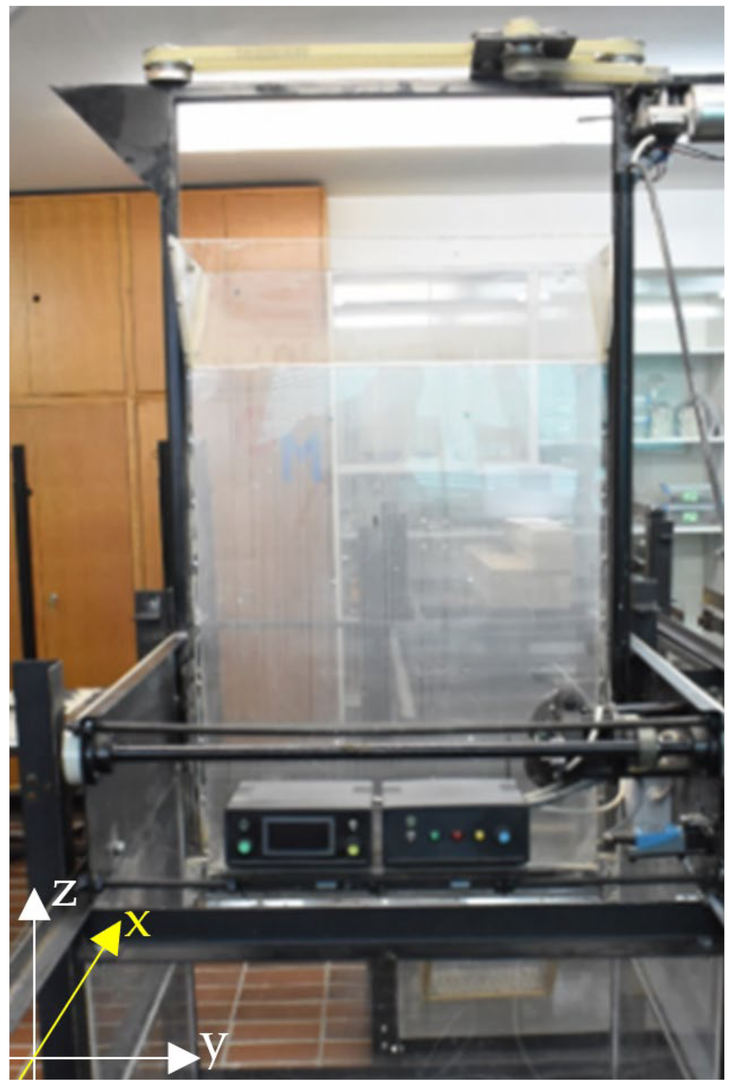
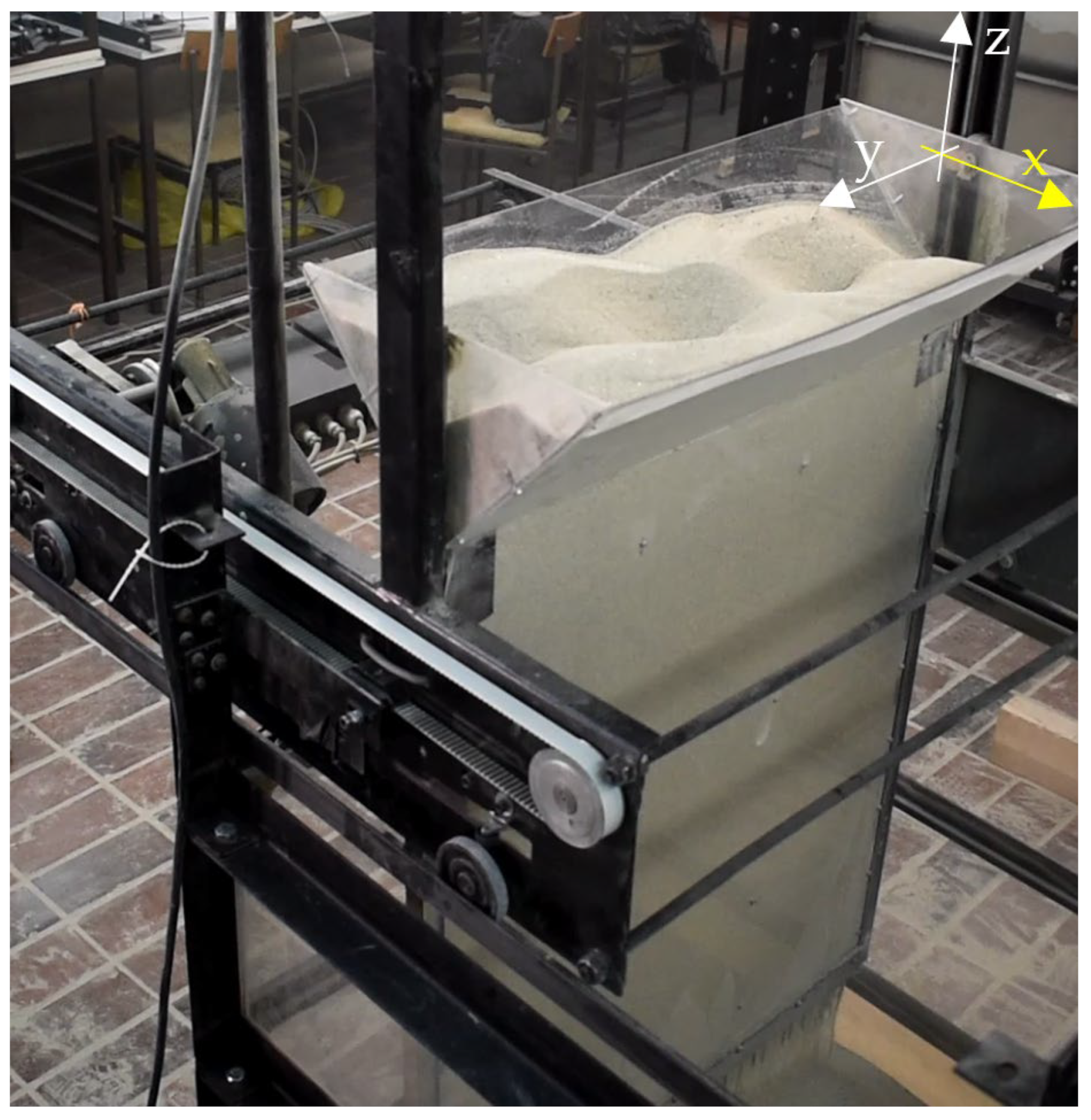
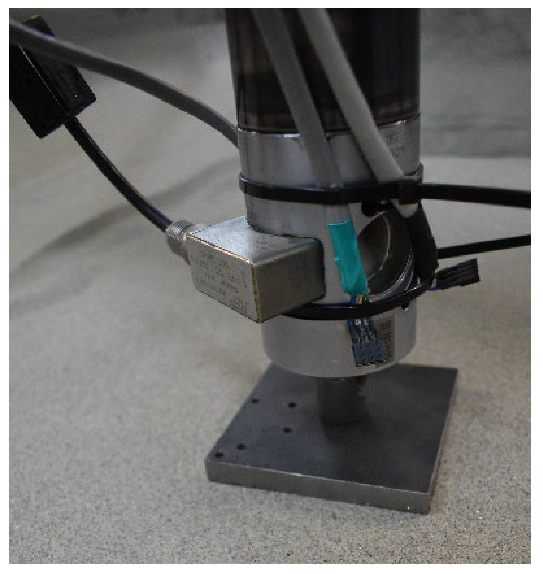
For the purpose of testing the piled raft 1g model, placed in loose sand, a self-propelled spreader, 70 cm wide, was made to fill the boxes with sand in the form of “sand rain” (Figure 15 and Figure 16).
The spreader has two control panels. One control panel serves to control the movement of the support brace within the box, with a switch for adjusting the speed of movement. The second control panel controls the support bracing box by adjusting the movement of the box in the z-direction, as well as the speed of box movement.

2.4. Testing Procedure

1. Prior to testing, the test box is filled with sand by means of a spreader, pouring sand in the form of sand rain from a height of 10 cm so that the sand remains loose after filling the box.
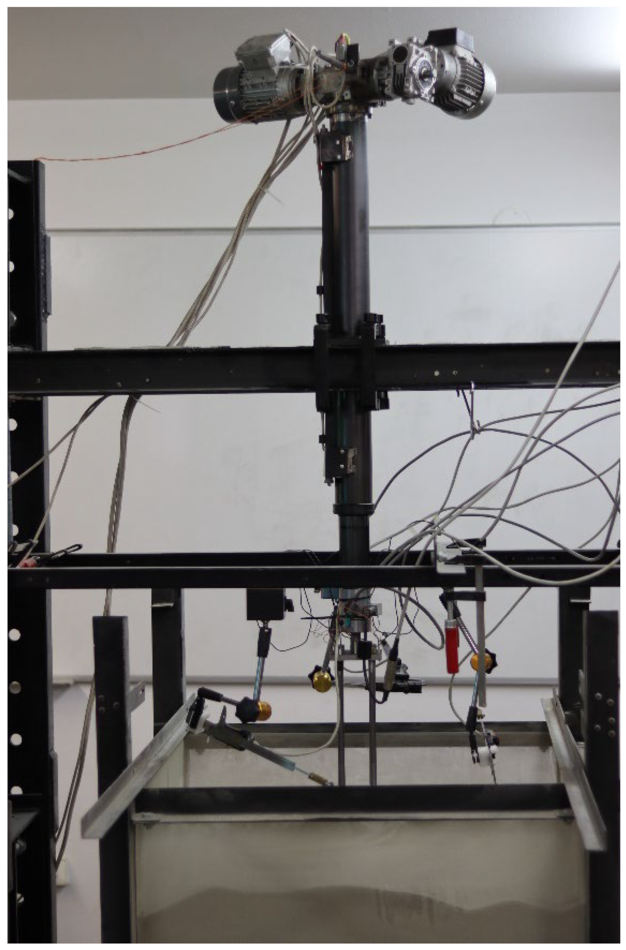
2. The filled sandbox is placed under previously installed test frame on which an engine with a mounted hydraulic piston is mounted. Load cell, which registers the vertical force on the system when pressing a group of piles into the sand, is mounted at the end of the piston.
3. The pre-assembled configuration of the piled raft is mounted on the load cell and the measuring equipment is connected to data logger (Figure 17).
4. Before applying the vertical compression force on the piled raft foundation model, spacers are placed between the piles at certain heights, ensuring that the piles remain vertical when pressed and are not skewed.
5. After the spacers are installed, the data logger is started, which is followed by final checking whether all measuring equipment is functional. The piles are driven in sand at a speed of 105 mm/min until the raft is at the height of 10 mm above the sand.
6. When the raft is at the height of 10 mm above the surface of the sand, the pressing speed is reduced to 1 mm/min and then the pressing continues until soil failure or until the raft is driven into the sand to a depth of 0.1B, where B is the width of the raft.
Figure 17. Photo showing the loading frame and measuring devices.
Applsci 13 00546 g017

3. Results and Discussion

3.1. Rafts without Piles

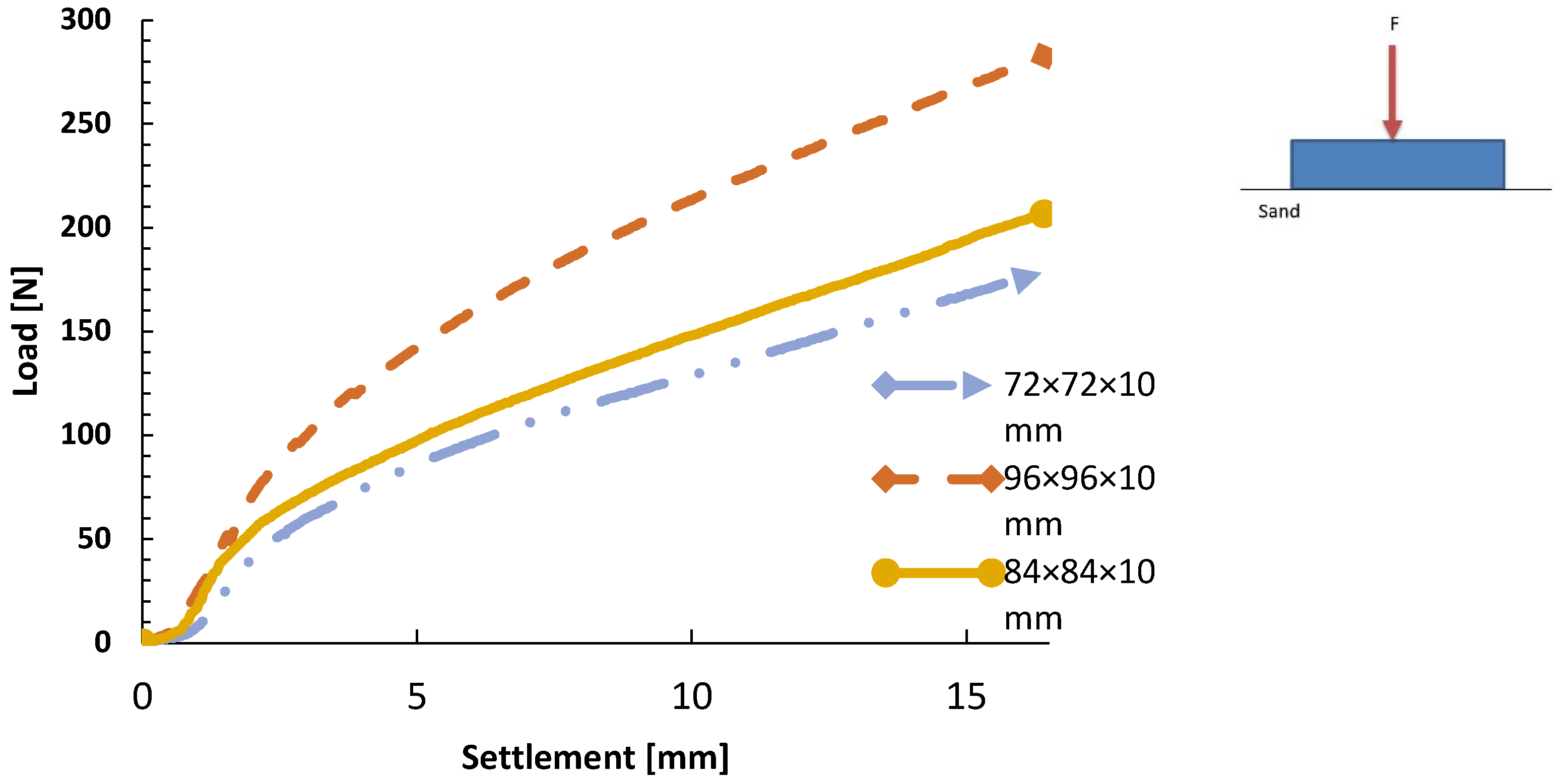
Load bearing curves for rafts without piles, driven into the sand to a depth of 0.1B, where B is the raft width, for raft dimensions 72 × 72 × 10 mm, 84 × 84 × 10 mm (Figure 18), 96 × 96 × 10 mm, are shown in Figure 19.
The results of the experiments show that, at the same external force, rafts with smaller contact area, i.e., smaller e/d ratio, have increased settlements, where “e” represents the distance between the pile axes and “d” is the pile diameter.

3.2. Piled Raft

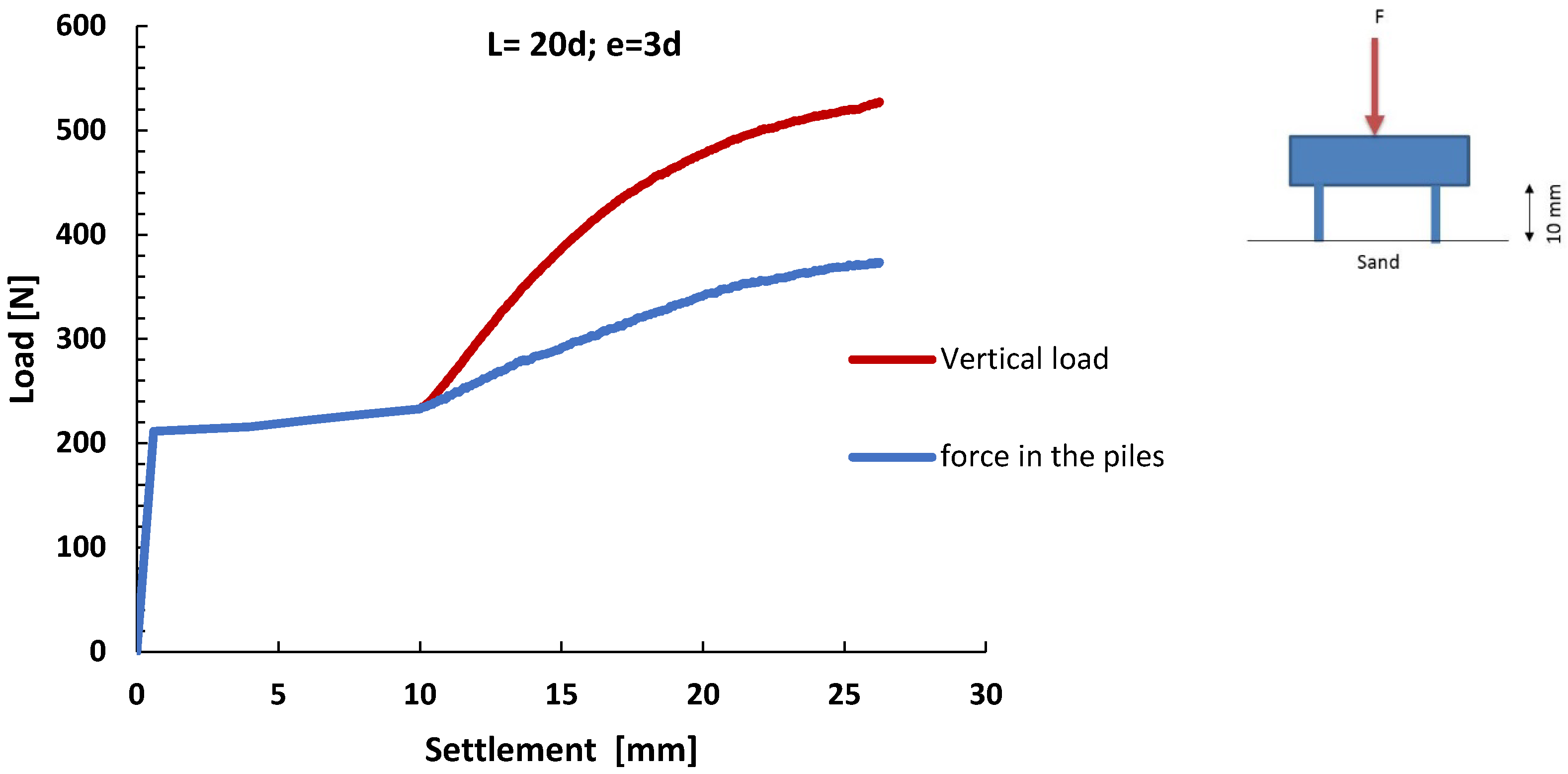
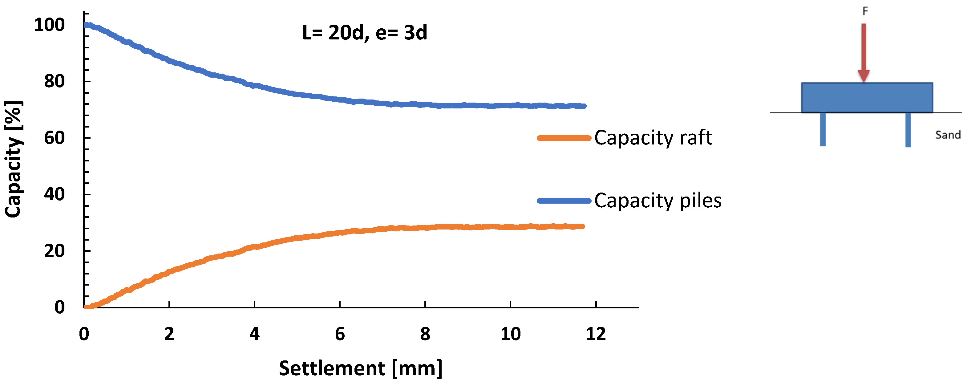
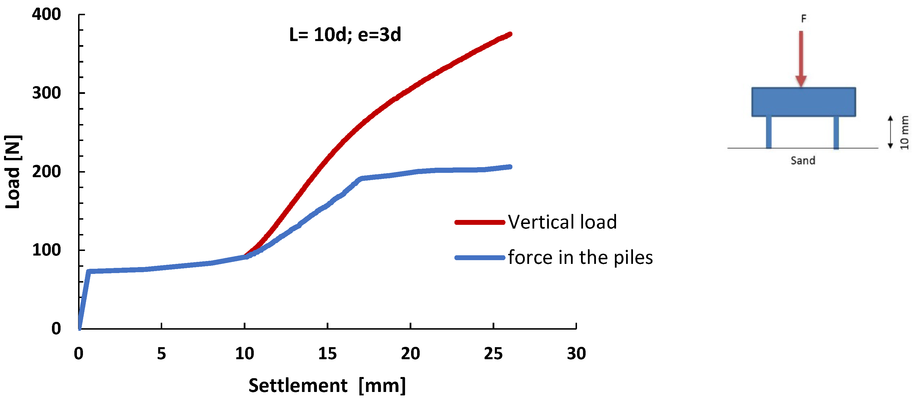
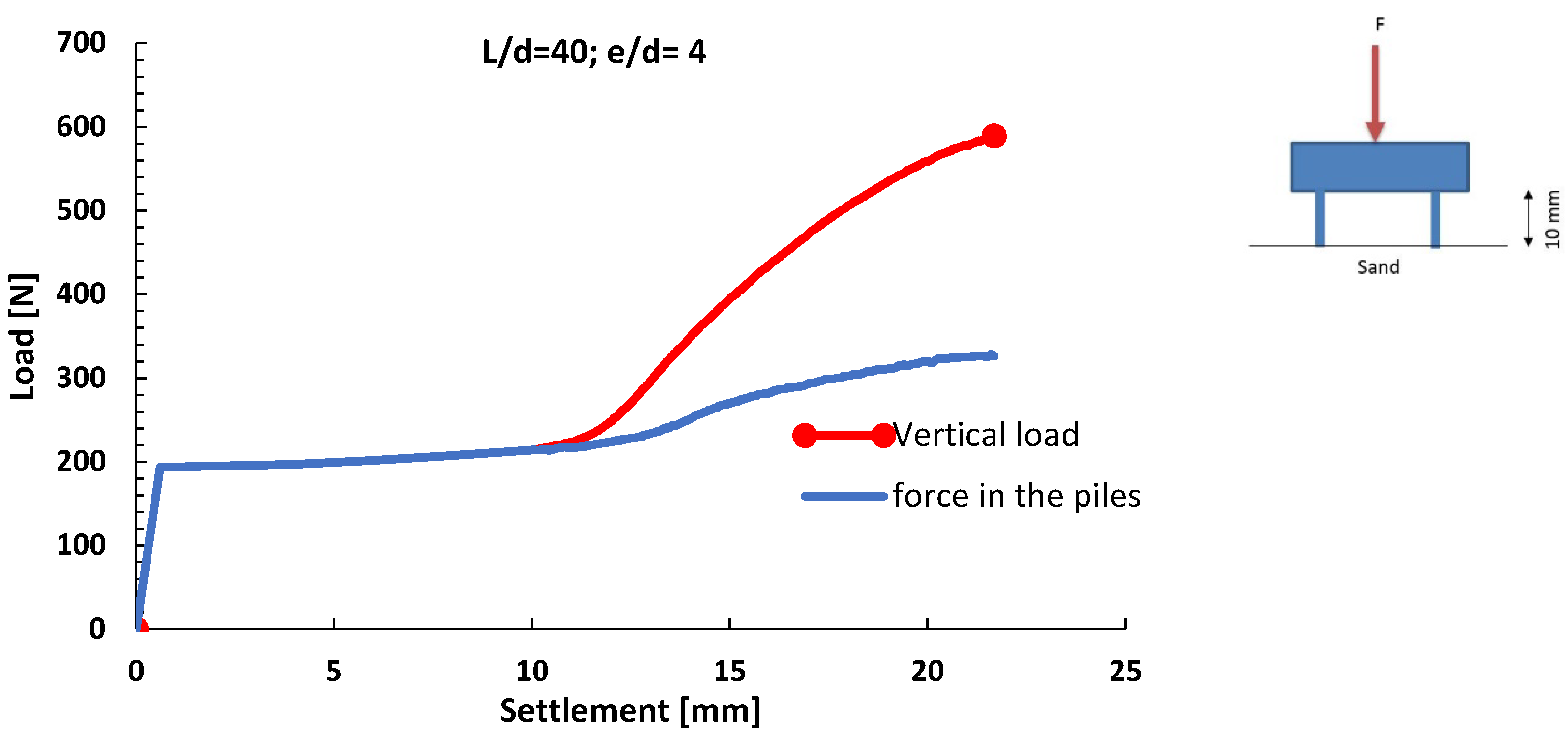
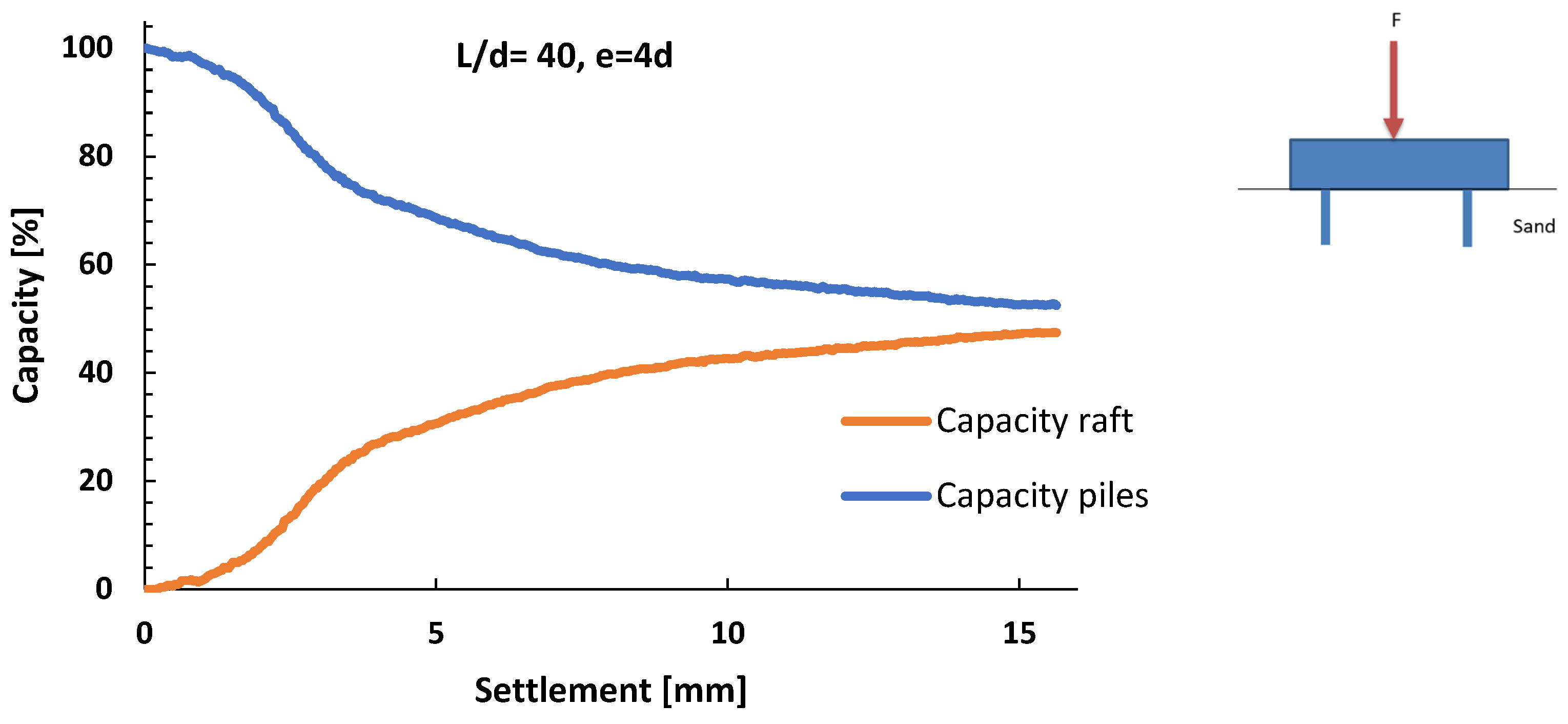
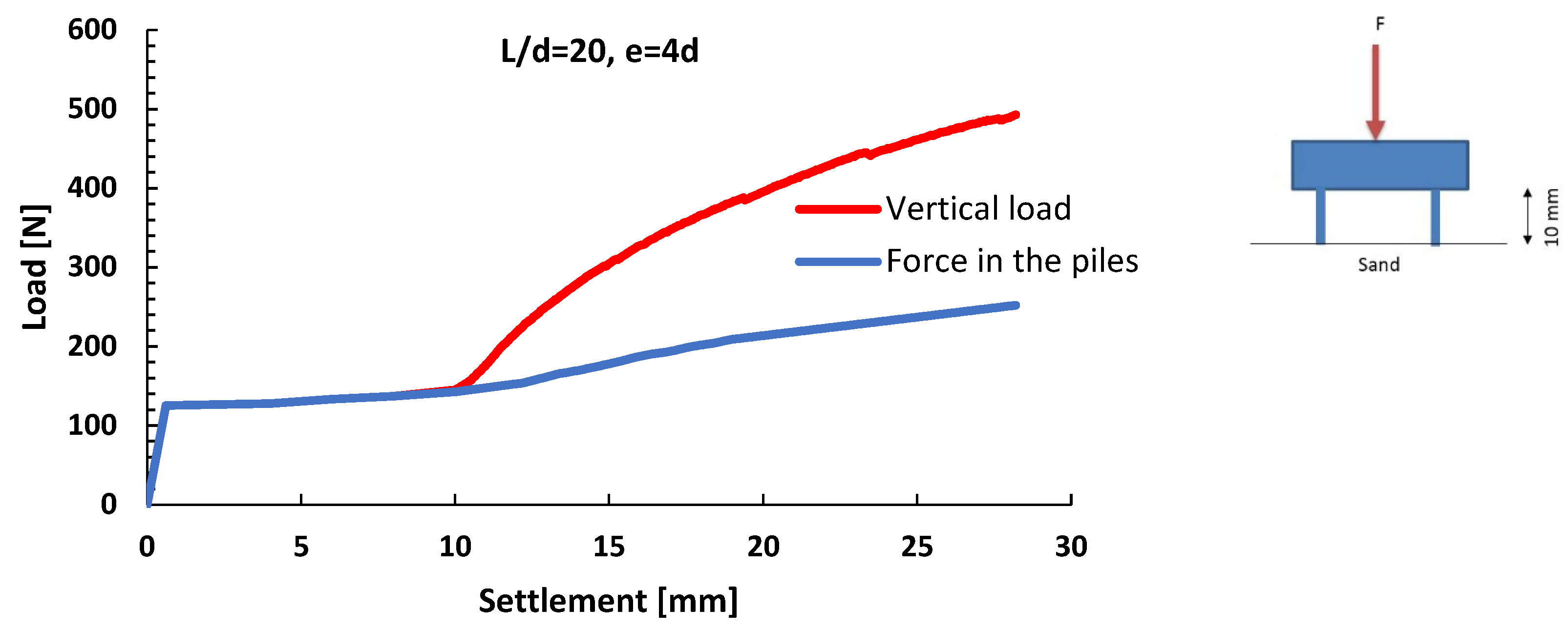
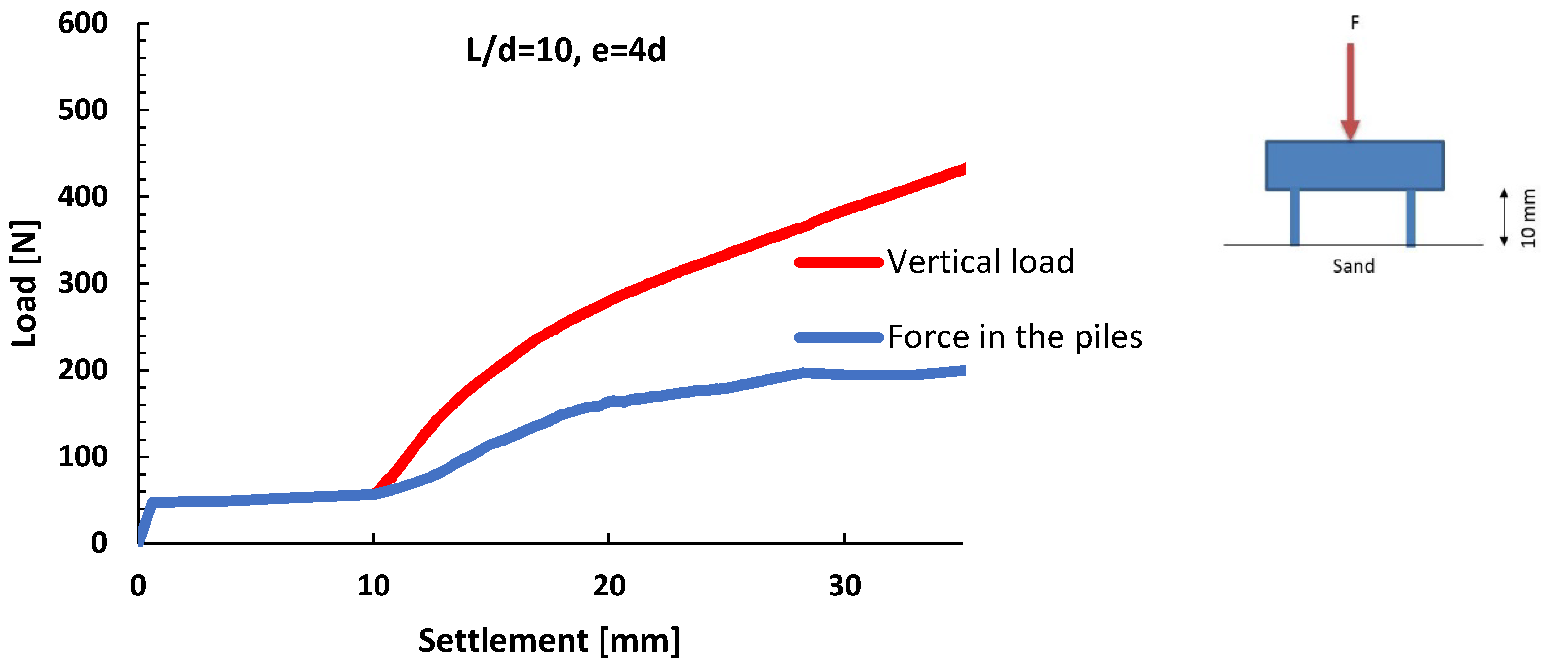
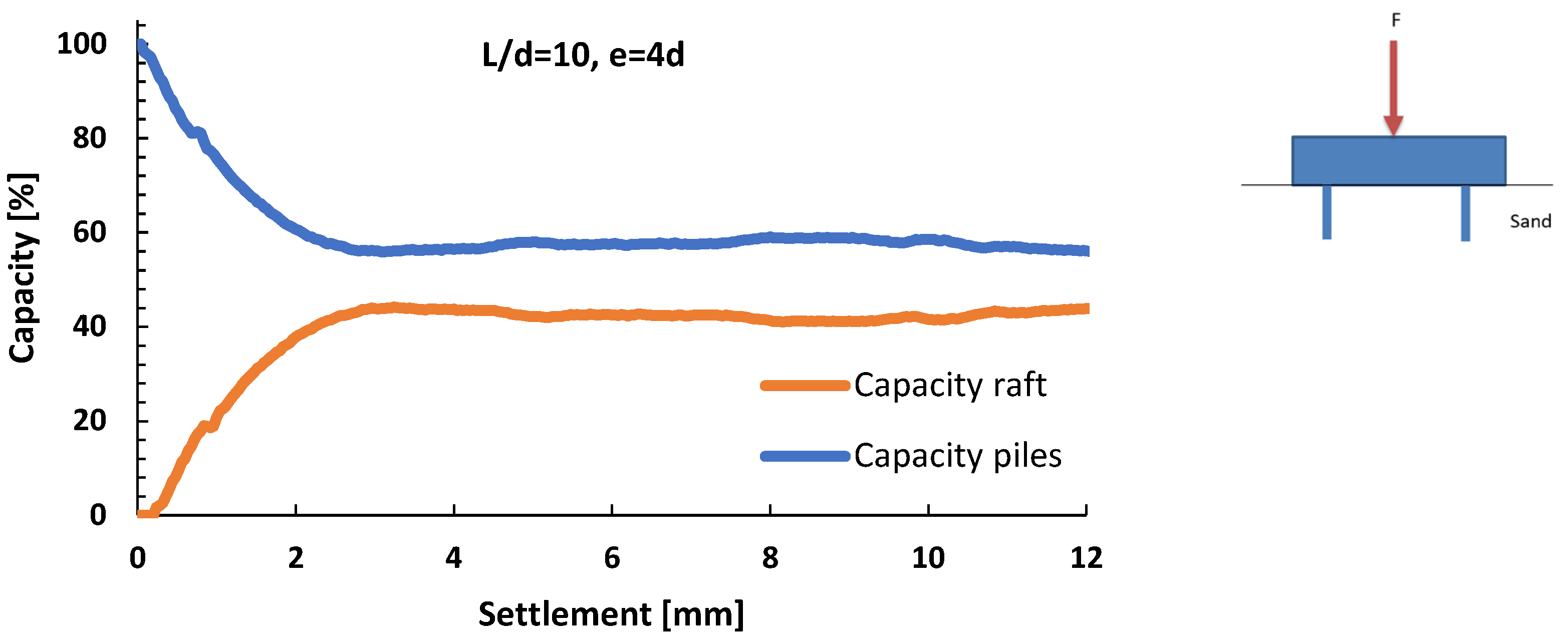
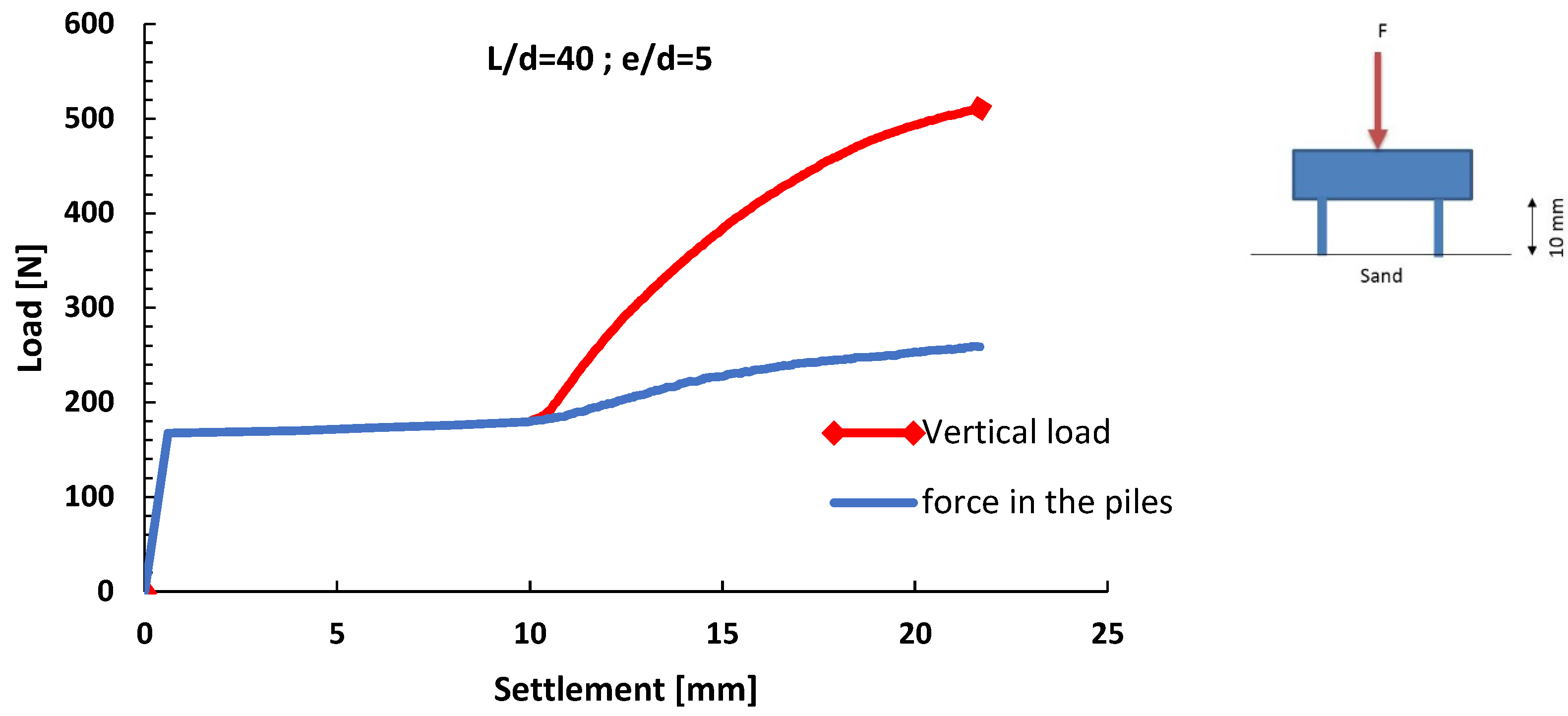
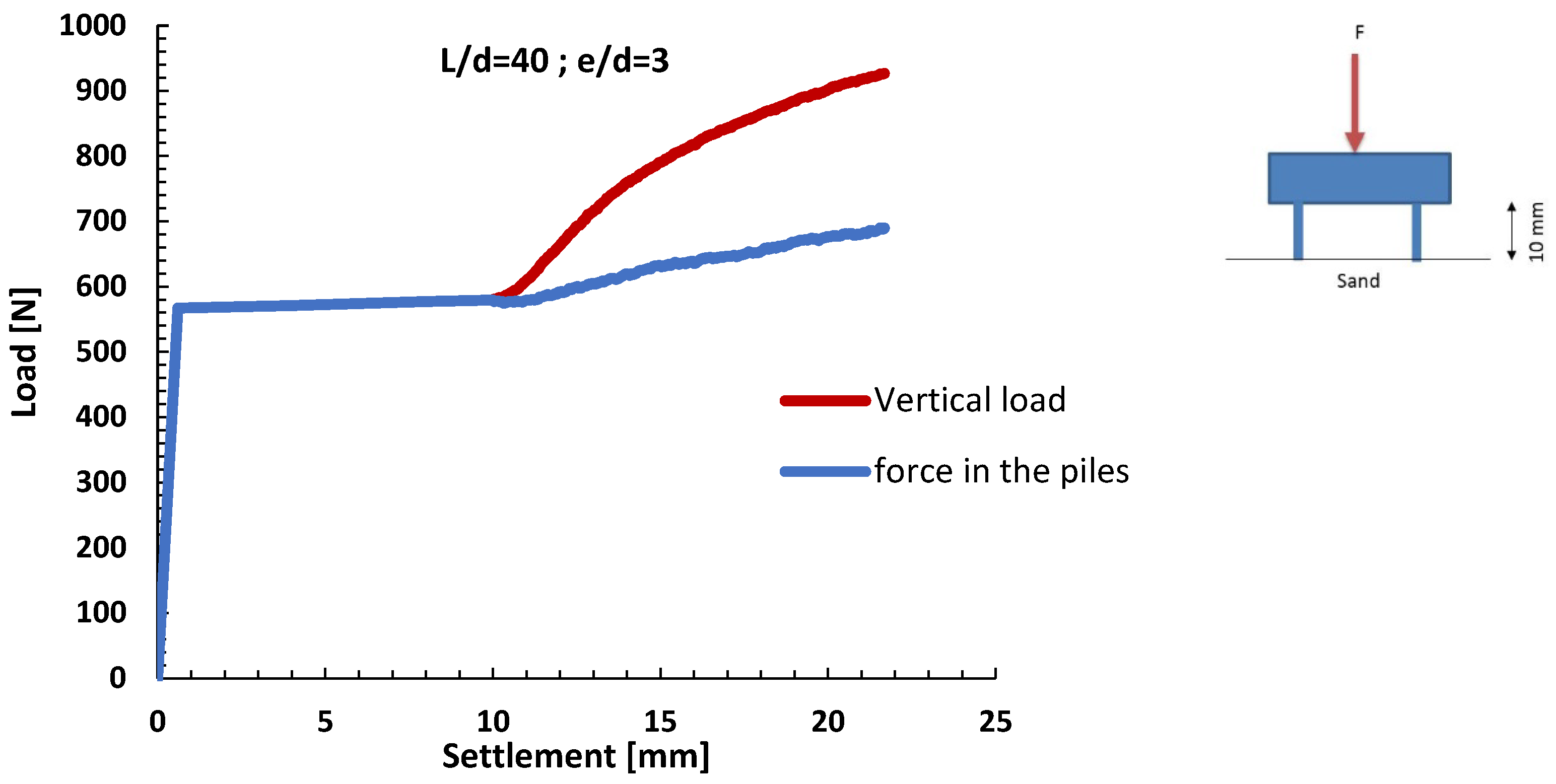
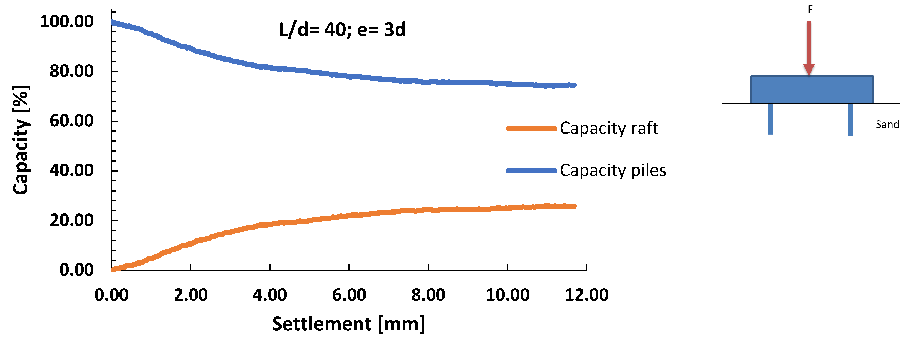
Within this experiment, load distribution between raft and piles, when the model was driven into loose sand, was analysed. Figure 20, Figure 21, Figure 22, Figure 23, Figure 24, Figure 25, Figure 26, Figure 27, Figure 28, Figure 29, Figure 30, Figure 31 and Figure 32 show “force–displacement” graphs of the piled raft for pile lengths of L/d = 40, 20, 10, which is often applicable in practice. The experiment was performed for pile distances of 3d, 4d, and 5d. The same layout was investigated by Marlapalle and others [63] in their experiments. From the graphs shown, it can be observed that, when settlement increases, the raft is activated, and, as the settlement further increases, the part of the force carried by the raft also increases. The final settlement criterion was defined to be a settlement of 0.1B, measured from the moment when the raft makes contact with the sand. The graphs show the portion of the load taken by the raft.
Figure 20 and Figure 21 show the “force–displacement” graphs, i.e., “load bearing capacity–settlement”, for piles with a length of 40d at a distance of 3d. The results show that, if a value of 0.1B is chosen for limit settlement, measured from the moment the raft touches the soil (here, approximatively 7 mm), the piles carry 76% of the total load.
Figure 22. Diagram “force–displacement” of piled raft L/d = 20, e/d = 3.
Applsci 13 00546 g022
Figure 23. Load distribution graph for the group of 4 piles with 20d length at the distance of e = 3d.
Applsci 13 00546 g023
Figure 22 and Figure 23 show the “force–displacement” graphs, i.e., “load bearing capacity–settlement”, for piles with a length of 20d at a distance of 3d. The results show that, if a value of 0.1B is chosen for limit settlement, measured from the moment the raft touches the soil (here, approximatively 7 mm), the piles carry 72% of the total load.
Figure 24. Diagram “force–displacement” of piled raft L/d = 10, e/d = 3.
Applsci 13 00546 g024
Figure 25. Load distribution graph for the group of 4 piles with 10d length at the distance of e= 3d.
Applsci 13 00546 g025
Figure 24 and Figure 25 show the “force–displacement” graphs, i.e., “load bearing capacity–settlement”, for piles with a length of 10d at a distance of 3d. The results show that, if a value of 0.1B is chosen for limit settlement, measured from the moment the raft touches the soil (here, approximatively 7 mm), the piles carry 74% of the total load.
Figure 26. Diagram “force–displacement” of piled raft L/d = 40, e/d = 4.
Applsci 13 00546 g026
Figure 27. Load distribution graph for the group of 4 piles with 40d length at the distance of e = 4d.
Applsci 13 00546 g027
Figure 26 and Figure 27 show the “force–displacement” graphs, i.e., “load bearing capacity–settlement”, for piles with a length of 40d at a distance of 4d. The results show that, if a value of 0.1B is chosen for limit settlement, measured from the moment the raft touches the soil (here, approximatively 7 mm), the piles carry 60% of the total load.
Figure 28. Diagram “force–displacement” of piled raft L/d = 20, e/d = 4.
Applsci 13 00546 g028
Figure 29. Load distribution graph for the group of 4 piles with 20d length at the distance of e = 4d.
Applsci 13 00546 g029
Figure 28 and Figure 29 show the “force–displacement” graphs, i.e., “load bearing capacity–settlement”, for piles with a length of 20d at a distance of 4d. The results show that, if a value approximatively 8 mm is chosen for limit settlement, the piles carry 55% of the total load.
Figure 30. Diagram “force–displacement” of piled raft L/d = 10, e/d = 4.
Applsci 13 00546 g030
Figure 31. Load distribution graph for the group of 4 piles with 10d length at the distance of e = 4d.
Applsci 13 00546 g031
Figure 30 and Figure 31 show the “force–displacement” graphs, i.e., “load bearing capacity–settlement”, for piles with a length of 10d at a distance of 4d. The results show that, if a value approximatively 8 mm is chosen for limit settlement, the piles carry 58% of the total load.
Figure 32. Load distribution graph for the piled raft L/d = 40, e/d = 5.
Applsci 13 00546 g032
Figure 32 shows the “force–displacement” graphs for piles with a length of 40d at a distance of 5d. The results show that, if a value of approximatively 9 mm is chosen for limit settlement, the piles carry 53% of the total load.
Previous diagrams show that, when designing piled raft foundations, the calculation should not be based on the required number of piles that should accept the entire load but on the number of piles needed to reduce the settlement to the allowable limits.
Long Phung [34] presented the measurement results of a load distribution mechanism for the Messe-Torhaus building in Frankfurt, 30 floors high and 130 m high. The building has a piled raft foundation, with raft dimensions of 24.5 × 17.5 m and pile spacing of about 3d. The established load distribution was such that about 25% of the total load was taken over by the raft, which corresponds to measurements obtained in this paper for the pile spacing of 3d. Long Phung [64] analysed the foundations of the ICC shopping centre in Hong Kong, one of the ten tallest buildings in the world, by means of numerical analysis with PLAXIS software and obtained that 30% of the total load is carried by the raft, which also corresponds to the range of measured results obtained by this experiment.

3.3. Influence of Pile Distance—Group Effect

Within the experiment, the influence of pile spacing on the relationship between load and settlement in a piled raft foundation system was investigated, as well as the distribution of forces between piles and raft.
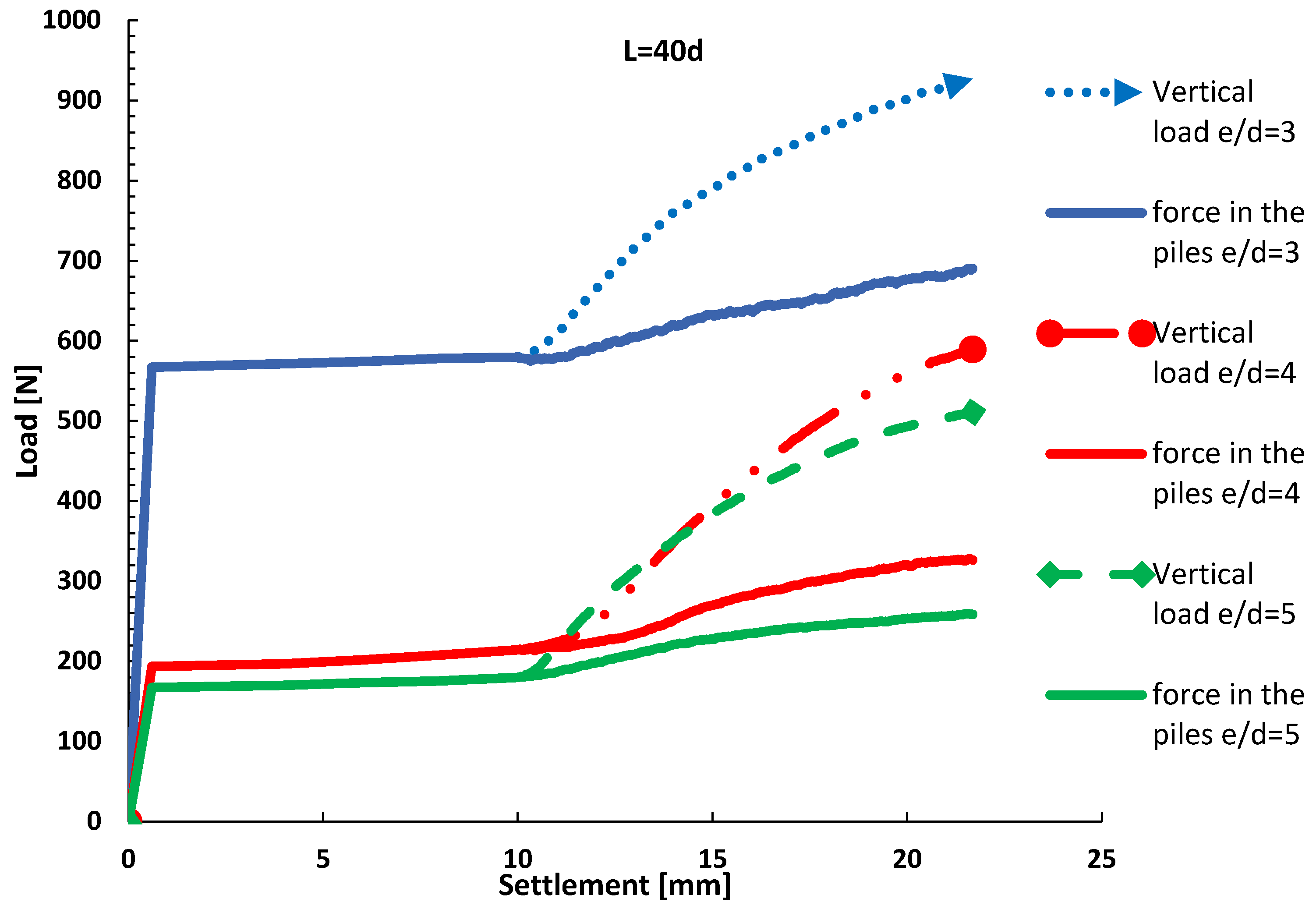
The diagram in Figure 33 shows that pile spacing has an effect on the relationship between load and settlement of this combined foundation system. This influence is much more pronounced when the spacing is e/d = 3 or smaller when compared to models with pile spacing of e/d = 4 and 5. Smaller pile spacing provides significant improvement in the performance of the piled raft foundation, and, accordingly, increased spacing of the piles leads to increased settlement of the foundation. Pile spacing also affects the distribution of forces between the piles and the raft.
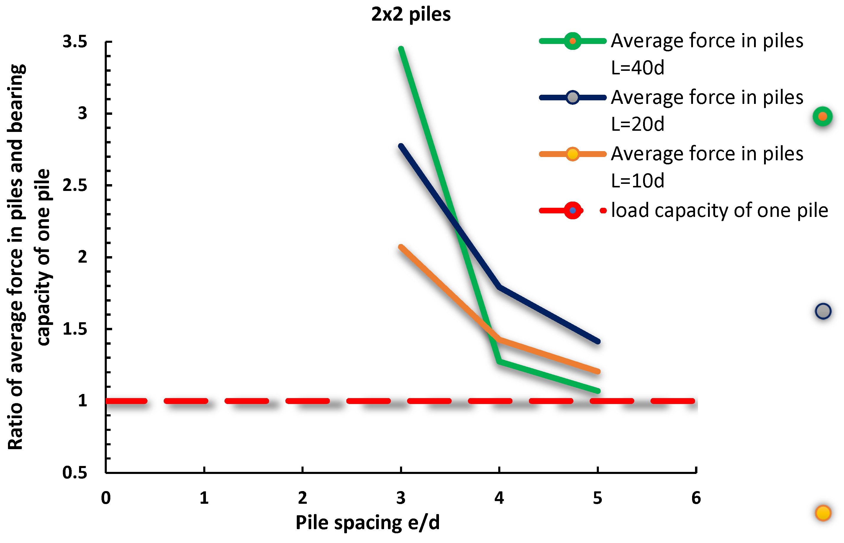
Figure 34 shows the effect of a group of piles. It can be observed that the shape of the curve is approximately the same for pile lengths of 10d and 20d, while the curve for pile length of 40d has a slightly different shape. Moreover, the effect of the pile group at a pile distance of 3d is much more pronounced, about 2.72 times larger, when compared to the pile distance of 4d. For piles of lengths 20d and 10d, the effect of the pile group at a distance of 3d is, in relation to a pile distance of 4d, about 1.55 times greater for a length of 20d and about 1.45 times greater for a length of 10d. It was also observed that, with a pile length of 40d at distances greater than 5d, the group effect is lost and the piles start to behave as individual piles, while, for piles of 10d and 20d length, the group effect can still be observed. Similar conclusions were reached by Sharafkhah et al. in their work [65].
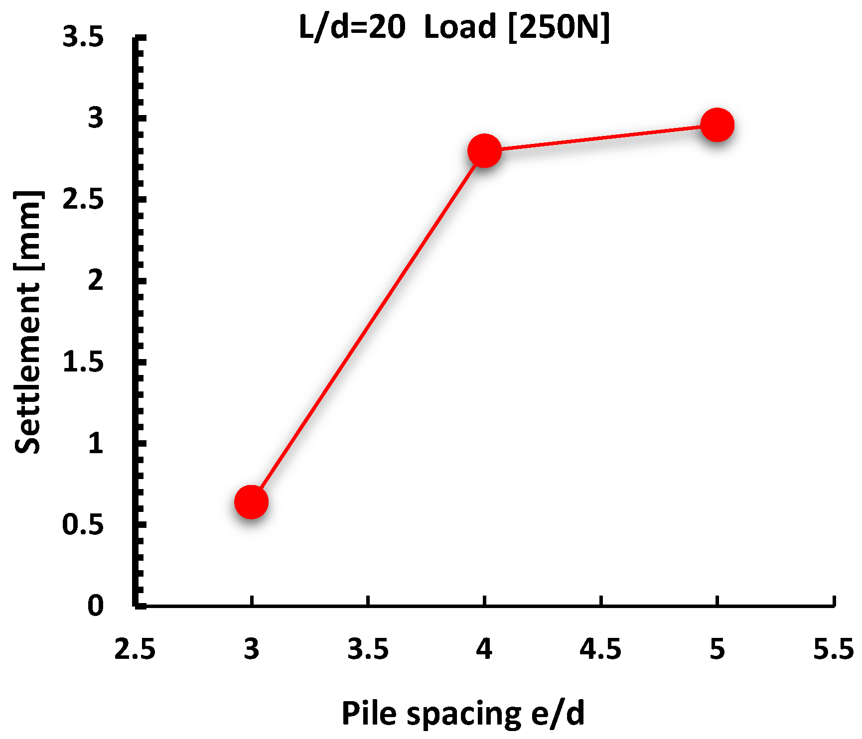
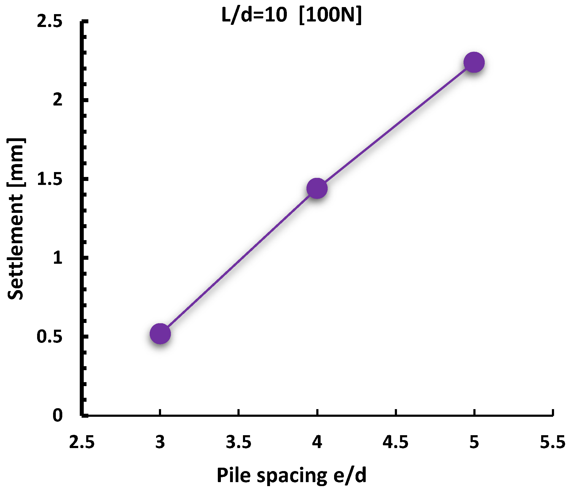
Figure 35, Figure 36 and Figure 37 show the value of settlement of the raft for the same pile lengths at a mutual distance of 3d, 4d, and 5d. It can be observed that, in all three cases, the settlement is greater at the same force for rafts with a greater distance between piles and the shapes of the curves for lengths of 40d and 20d are similar, while, for a length of 10d, the settlement increases linearly with increasing distance between piles.

3.4. The Effect of Length

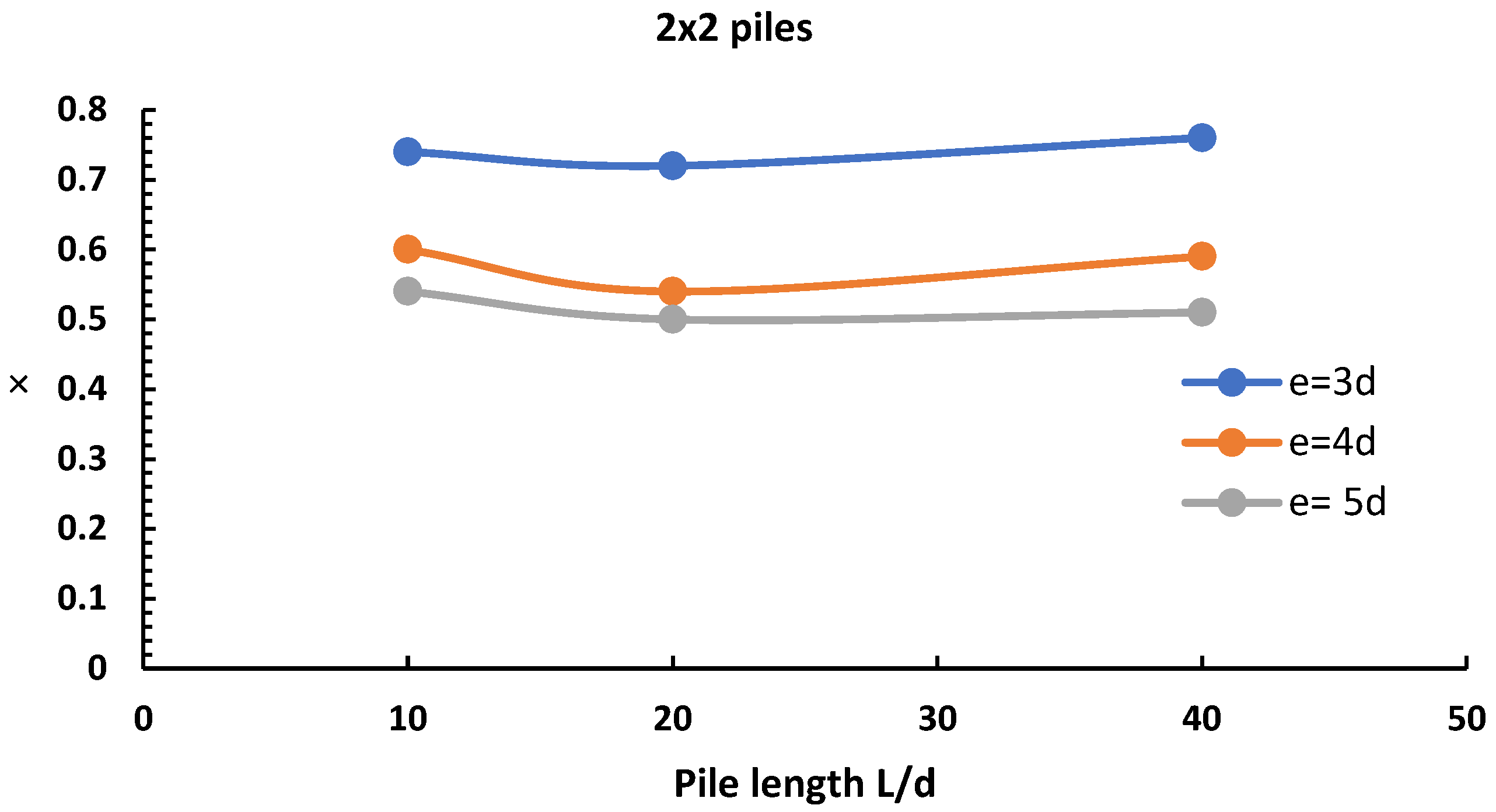
The experimental analysis found that the length of the piles has no particular effect on the load distribution between the raft and the piles, as shown in the following figure.
It was observed that, after the yield point of the foundation system, the stiffness of the raft is not affected by the change in the length of the piles, which can be concluded from Figure 38. On the other hand, the bearing capacity of the foundation increases significantly with an increase in the length of the piles before and after the yield point. Similar observations were made in the studies by Omekan [66] and El Sawwaf [67].

3.5. Load Bearing Capacity of the Raft with and without Rafts

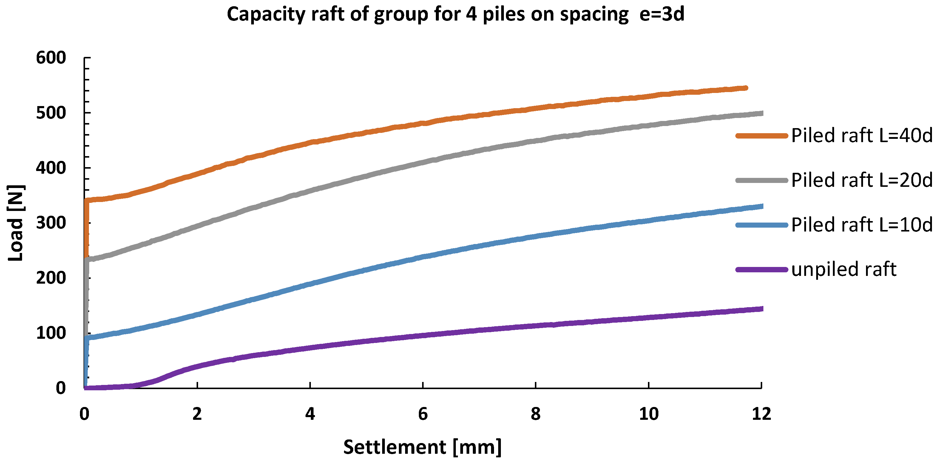
Figure 39 shows the bearing capacity of piled rafts and rafts without piles for pile spacing of 3d and pile lengths of 40d, 20d, and 10d. For a raft settlement of 0.1B, which is approximately 7 mm, the bearing capacity of the piled raft foundation system with piles of length 10d is about 2.43 times higher than for the raft without piles. The bearing capacity of the piled raft on piles with a length of 20d is greater by about 1.67 times than for the piled raft with piles of 10d length, while the bearing capacity of the piled raft with piles of 40d length is greater by about 1.15 times than the piled raft with piles of 20d length.
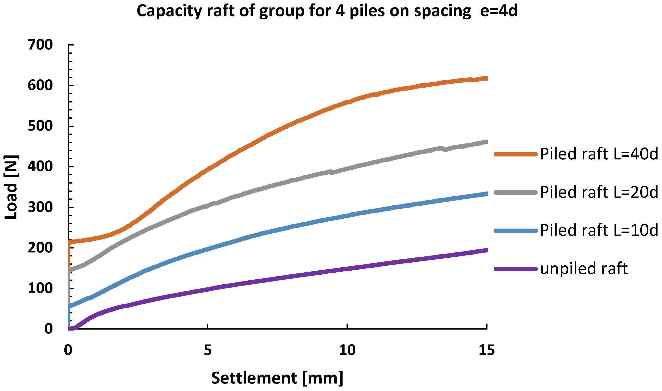
Figure 40 shows the bearing capacity of piled rafts and rafts without piles for pile spacing of 4d and pile lengths of 40d, 20d, and 10d. For a raft settlement of 0.1B, which is approximately 8 mm, the bearing capacity of the piled raft foundation system with piles of length 10d is about 1.95 times higher than for the raft without piles. The bearing capacity of the piled raft on piles with a length of 20d is greater by about 1.45 times than for the piled raft with piles of 10d length, while the bearing capacity of the piled raft with piles of 40d length is greater by about 1.38 times than the piled raft with piles of 20d length.
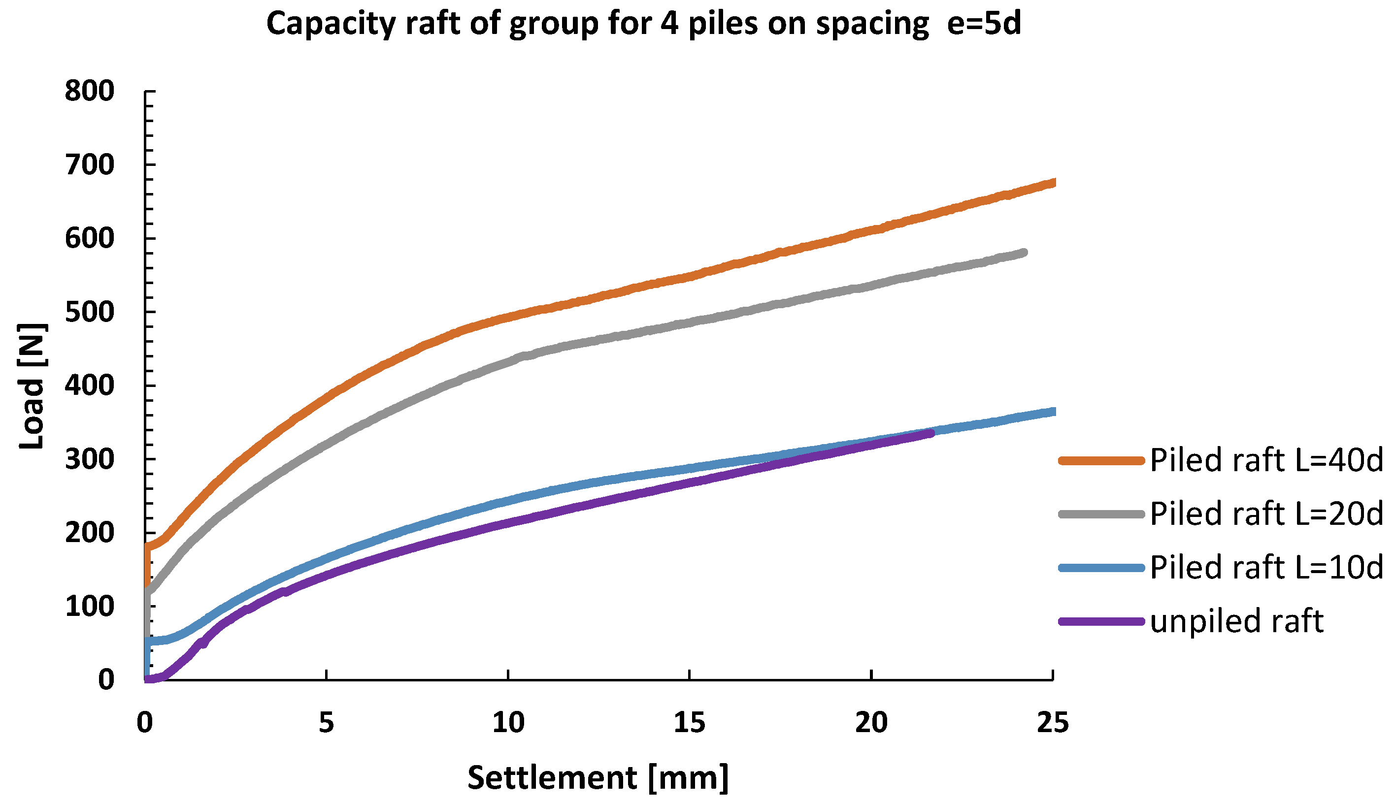
Figure 41 shows the bearing capacity of piled rafts and rafts without piles for pile spacing of 5d and pile lengths of 40d, 20d, and 10d. For a raft settlement of 0.1B, which is approximately 9 mm, the bearing capacity of the piled raft foundation system with piles of length 10d is about 1.15 times higher than for the raft without piles. The bearing capacity of the piled raft on piles with a length of 20d is greater by about 1.79 times than for the piled raft with piles of 10d length, while the bearing capacity of the piled raft with piles of 40d length is greater by about 1.16 times than the piled raft with piles of 20d length.

4. Conclusions

Based on experimental results, the following conclusions were reached:
  • Application of small-scale 1g models for pile bearing capacity estimation in loose sand is justified for this research because there is no significant scale effect that could originate from the curved strength envelope for dense sand.
  • For the same external force, a raft with smaller contact area, i.e., smaller e/d ratio, and smaller pile slenderness (L/d) has higher settlements.
  • For the same external force and same e/d ratio, an increase in pile slenderness ratio L/d reduces settlement of the raft.
  • The scientific contribution of this paper is showing that the influence of scale effect on estimation of pile bearing capacity in loose sand that has a constant value of the angle of shearing resistance is negligible. In other words, application of 1g models on assessment of the bearing capacity of piles in loose sand is not essentially related to the size of the model. By contrast, in dense sand, the shear resistance envelope is curved. This means that the mobilized angle of shearing resistance at smaller pile dimensions is smaller; i.e., the average normal stress is lower and vice versa, or, in other words, the scale effects become significant.
  • Piled raft foundation systems with smaller contact surfaces at the same load levels have higher settlements than systems with larger contact surfaces; the increase in the raft contact surface improves the load bearing capacity of the piled raft foundation system at the same settlement values. This improvement in performance is caused by the horizontal pressures in the soil beneath the raft, which increase the friction between the soil and the pile surface, therefore increasing the load bearing capacity of the whole piled raft foundation system.
  • When driving in a group of piles, as soon as the raft makes contact with the sand, the raft is activated, and its load bearing contribution increases as settlement increases.
  • For the case of raft settlement at a value of 0.1B, where B is the width of the pile, depending on the distance between the piles, the pile carries about 24% to 50% of the total load acting on the foundation system.
  • The length of the piles does not play a significant role in the distribution of the load between the raft and the piles.
  • For the pile spacing of 3d, the pile group effect is very pronounced, while, as the spacing increases, the pile group effect decreases. It was concluded that the pile spacing of 5d represents the upper boundary value, after which the pile group effect contribution to the load bearing capacity is lost.

Author Contributions

N.B.—writing—original draft preparation; I.D.—supervision, review, editing; D.K.—methodology, review, editing. All authors have read and agreed to the published version of the manuscript.

Funding

The publication of this research was supported by the company “Construction Center Ltd.” from Subotica, Serbia.

Institutional Review Board Statement

Not applicable.

Informed Consent Statement

Not applicable.

Data Availability Statement

Not applicable.

Acknowledgments

The paper presents the results of an experiment conducted for the purpose of writing a doctoral thesis by Nemanja Bralović, which has not yet been published. We thank Petar Santrač and Željko Bajić for their cooperation and donated measuring equipment for the experiment.

Conflicts of Interest

The authors declare no conflict of interest.

References

  1. Du, D.; Zhuang, Y.; Sun, Q.; Yang, X.; Dias, D. Bearing Capacity Evaluation for Shallow Foundations on Unsaturated Soils Using. Comput. Geotech. 2021, 137, 104309. [Google Scholar] [CrossRef]
  2. Rui, Z.; Feng, Z.; Zhihui, W.; Shengjun, D.; Xin, D.; Zekun, Z.; Wei, X. Improving the Performance of Piled Raft Foundations Using Deformation Adjustors: A Case Study. Buildings 2022, 12, 1903. [Google Scholar]
  3. Wu, J.T.; El Naggar, M.H.; Zhao, S.; Wen, M.J.; Wang, K.H. Beam-unequal length piles-soil coupled vibrating system considering pile-soil-pile interaction. J. Bridge Eng. 2021, 26, 04021086. [Google Scholar] [CrossRef]
  4. Zhang, Y.P.; Wu, W.B.; Zhang, H.K.; El Naggar, M.H.; Wang, K.H.; Jiang, G.H.; Mei, G.X. A novel soil-pile interaction model for vertical pile settlement prediction. Appl. Math. Model. 2021, 99, 478–496. [Google Scholar] [CrossRef]
  5. El-Garhy, B.; Galil, A.A.; Youssef, A.F.; Raia, M.A. Behavior of raft on settlement reducing piles: Experimental model study. J. Rock Mech. Geotech. 2013, 5, 389–399. [Google Scholar] [CrossRef] [Green Version]
  6. Burland, J.B.; Kantez, B.A.; Broms, B.B. Behaviour of foundations and structures. In Proceedings of the 9th ICSMFE, Tokyo, Japan, 11–15 July 1977; pp. 495–546. [Google Scholar]
  7. Berezantzev, V. Load Bearing Capacity and Deformation of Piled Foundations. In Proceedings of the Fifth International Conference on Soil Mechanics and Foundation Engineering, Paris, France, 17–22 July 1961. [Google Scholar]
  8. Burland, J. Shaft Friction of Piles in Clay—A Simple Fundamental Approach; Ground Engineering: London, UK, 1973. [Google Scholar]
  9. Poulos, H.G. Pile Behaviour—Theory and Application. Geotechnique 1989, 39, 365–415. [Google Scholar] [CrossRef]
  10. Poulos, H.; Small, J.; Chow, H. Piled Raft Foundations for Tall Buildings. Geotech. Eng. J. SEAGS AGSSEA 2011, 42, 78–84. [Google Scholar]
  11. Poulos, H.G.; Bunce, G. Foundation Design for the Burj Dubai—The World’s Tallest Building. In Proceedings of the 6th International Conference on Case Histories in Geotechnical Engineering, Arlington, VA, USA, 11–16 August 2008. [Google Scholar]
  12. Irfan, J.; Irshad, A.; Wali, U.; Mahmood, A.; Mohanad, M.; Sabri, S.; Ali, M. Experimental Study on Lateral and Vertical Capacity of Piled Raft and Pile Group System in Sandy Soil. Appl. Sci. 2022, 12, 8853. [Google Scholar]
  13. Bhartiya, P.; Chakraborty, T.; Basu, D. Load-settlement response of piled raft foundations in sand. Geomech. Geoengin. 2021, 17, 1260–1283. [Google Scholar] [CrossRef]
  14. Jose, M.; Krishnan, K.D.; Ravichandran, P. Behaviour of vertically loaded piled raft system on cohesionless soil. Mater. Today Proc. 2020, 40, S167–S171. [Google Scholar] [CrossRef]
  15. Diptesh, C.; Rajib, S.; Sumanta, H. Behaviour of piled raft foundation in sand subjected to combined V-M-H loading. Ocean Eng. 2020, 2016, 107596. [Google Scholar]
  16. Zhi, Y.A.; Zhong, H.C.; Yi, C.C. Time effect of vertically loaded piled rafts in layered cross-anisotropic viscoelastic saturated soils. Comput. Geotech. 2020, 119, 103384. [Google Scholar]
  17. Banerjee, R.; Bandyopadhyay, S.; Sengupta, A.; Reddy, G.R. Settlement behaviour of a pile raft subjected to vertical loadings in multilayered soil. Geomech. Geoengin. 2022, 17, 282–296. [Google Scholar] [CrossRef]
  18. Rajib, M.; Baleshwar, S. A parametric study of large piled raft foundations on clay soil. Ocean Eng. 2022, 262, 112251. [Google Scholar]
  19. Bayram, A.; Erol, Ş. Experimental and Numerical Investigation of Load Sharing Ratio for Piled Raft Foundation in Granular Soils. KSCE J. Civ. Eng. 2022, 26, 1662–1673. [Google Scholar]
  20. Chow, H.; Small, J. Behaviour of Piled Rafts with Piles of Different Lengths and Diameters under Vertical Loading. In Advances in Deep Foundations, Proceedings of the Geo-Fronties Congress, Austin, TX, USA, 24–26 January 2005; American Society of Civil Engineers (ASCE): Reston, VA, USA, 2005; pp. 1–15. [Google Scholar]
  21. Barreto, E.D.S.; Stafanato, K.V.; Marvila, M.T.; de Azevedo, A.R.G.; Ali, M.; Pereira, R.M.L.; Monteiro, S.N. Clay Ceramic Waste as Pozzolan Constituent in Cement for Structural Concrete. Materials 2021, 14, 2917. [Google Scholar] [CrossRef]
  22. De Azevedo, A.R.; Marvila, M.T.; Ali, M.; Khan, M.I.; Masood, F.; Vieira, C.M.F. Effect of the Addition and Processing of Glass Polishing Waste on the Durability of Geopolymeric Mortars. Case Stud. Constr. Mater. 2021, 15, e00662. [Google Scholar] [CrossRef]
  23. Gad, M.A.; Riad, A.M.; Nikbakht, E.; Ali, M.; Ghanem, G.M. Structural Behavior of Slender Reinforced Concrete Columns Wrapped with Fiber Reinforced Polymers Subjected to Eccentric Loads. In Proceedings of the 2020 Second International Sustainability and Resilience Conference, Technology and Innovation in Building Designs, Sakheer, Bahrain, 11–12 November 2020; pp. 1–5. [Google Scholar]
  24. Li, L.; Liu, X.; Liu, H.; Wu, W.; Lehane, B.M.; Jiang, G.; Xu, M. Experimental and numerical study on the static lateral performance of monopile and hybrid pile foundation. Ocean Eng. 2022, 255, 111461. [Google Scholar] [CrossRef]
  25. Khurshed, R.D.; Abbas, J.M. An Experimental Investigation the Response of Pile Groups to Inclined Cyclic Loading in Sandy Soil. Geotech. Eng. Sustain. Constr. 2022, 1, 435–446. [Google Scholar]
  26. Qiang, F.; Jie, Y. Experimental and Numerical Study of the Dynamic Response of XCC Pile–Raft Foundation under High-Speed Train Loads. Appl. Sci. 2022, 11, 9260. [Google Scholar]
  27. Meena, N.K.; Nimbalkar, S.; Fatahi, B.; Yang, G. Effects of soil arching on behavior of pile-supported railway embankment: 2D FEM approach. Comput. Geotech. 2020, 123, 1–16. [Google Scholar] [CrossRef]
  28. Deb, P.; Pal, S.K. Nonlinear analysis of lateral load sharing response of piled raft subjected to combined V-L loading. Mar. Georesour. Geotechnol. 2021, 39, 994–1014. [Google Scholar] [CrossRef]
  29. Plaban, D.; Barnali, D.; Rai, B.R.; Sujit, K.P. Structural analysis of piled raft foundation in soft soil: An experimental simulation and parametric study with numerical method. Ocean Eng. 2022, 261, 112139. [Google Scholar]
  30. Wenxuan, Z.; Guanlin, Y.; Linlin, G.; Feng, Z. 1g model test of piled-raft foundation subjected to vibration load and its simulation considering small confining stress. Soil Dyn. Earthq. Eng. 2022, 156, 107212. [Google Scholar]
  31. Syed, M.F.R.; Kuihua, W.; Fazal, E.J. Evaluating the response of piles subjected to static and multiple dynamic. Structures 2022, 40, 187–201. [Google Scholar]
  32. Hakro, M.R.; Kumar, A.; Almani, Z.; Ali, M.; Aslam, F.; Fediuk, R.; Klyuev, S.; Klyuev, A.; Sabitov, L. Numerical Analysis of Piled-Raft Foundations on Multi-Layer Soil Considering Settlement and Swelling. Buildings 2022, 12, 356. [Google Scholar] [CrossRef]
  33. Reul, O.; Randolph, M.F. Design Strategies for Piled Rafts Subjected to Nonuniform Vertical Loading. J. Geotech. Geoenviron. Eng. 2004, 130, 1125–1128. [Google Scholar] [CrossRef]
  34. Long, P.D. Piled Raft—A Cost-Effective Foundation Method for High-Rises. Geotech. Eng. J. SEAGS AGSSEA 2010, 41, 149. [Google Scholar]
  35. Bajad, S.P.; Sahu, R.B. An Experimental Study on the Behaviour of Vertically Loaded Piled. In Proceedings of the 12th International Conference of International Association for Computer Methods and Advances in Geomechanics (IACMAG), Goa, India, 1–6 October 2008. [Google Scholar]
  36. De Sanctis, L.; Mandolini, A. Bearing Capacity of Piled Rafts on Soft Clay Soils. J. Geotech. Geoenviron. Eng. 2006, 132, 1600–1610. [Google Scholar] [CrossRef]
  37. Fleming, K.; Weltman, A.; Randolph, M.; Elson, K. Piling Engineering; Taylor & Francis Group: New York, NY, USA, 2009; p. 95. [Google Scholar]
  38. Clancy, R. An Approximate Analysis Procedure for Piled Raft Foundations. Int. J. Numer. Anal. Methods Geomech. 1993, 17, 849–869. [Google Scholar] [CrossRef]
  39. Zhanabayeva, A.; Sagidullina, N.; Kim, J.; Satyanaga, A.; Lee, D.; Moon, S.-W. Comparative Analysis of Kazakhstani and European Design Specifications: Raft Foundation, Pile Foundation, and Piled Raft Foundation. Appl. Sci. 2021, 11, 3099. [Google Scholar] [CrossRef]
  40. Burland, J.; Burbidge, M.; Wilson, E.; Terzaghi, K. Settlement of Foundations on Sand and Gravel. Proc. Inst. Civ. Eng. 1985, 78, 1325–1381. [Google Scholar] [CrossRef]
  41. Ali, M.; Abbas, S.; Khan, M.I.; Gad, M.A.; Ammad, S.; Khan, A. Experimental Validation of Mander’s Model for Low Strength Confined Concrete Under Axial Compression. In Proceedings of the 2020 Second International Sustainability and Resilience Conference, Technology and Innovation in Building Designs, Sakheer, Bahrain, 11–12 November 2020; pp. 1–6. [Google Scholar]
  42. Mandolini, A.; di Laora, R.; Mascarucci, Y. Rational Design of Piled Raft. Procedia Eng. 2013, 57, 45–52. [Google Scholar] [CrossRef]
  43. Clancy, P.; Randolph, M.F. Simple design tools for piled raft foundations. Geotechnique 1996, 46, 313–328. [Google Scholar] [CrossRef]
  44. Zhao, T.-H.; Wang, M.-K.; Hai, G.-J.; Chu, Y.-M. Landen inequalities for Gaussian hypergeometric function. Rev. Real Acad. Cienc. Exactas Fís. Nat. Ser. A Mat. 2021, 116, 1–23. [Google Scholar] [CrossRef]
  45. Nazeer, M.; Hussain, F.; Khan, M.I.; Rehman, A.U.; El-Zahar, E.R.; Chu, Y.-M.; Malik, M. Theoretical study of MHD electro-osmotically flow of third-grade fluid in micro channel. Appl. Math. Comput. 2022, 420, 126868. [Google Scholar] [CrossRef]
  46. Chu, Y.-M.; Shankaralingappa, B.; Gireesha, B.; Alzahrani, F.; Khan, M.I.; Khan, S.U. Combined impact of Cattaneo-Christov double diffusion and radiative heat flux on bio-convective flow of Maxwell liquid configured by a stretched nano-material surface. Appl. Math. Comput. 2021, 419, 126883. [Google Scholar] [CrossRef]
  47. Kavitha, P.E.; Beena, K.S.; Narayanan, K.P. A review on soil–structure interaction analysis of laterally loaded piles. Innov. Infrastruct. Solut. 2016, 1, 14. [Google Scholar] [CrossRef] [Green Version]
  48. Bourgeois, E.; de Buhan, P.; Hassen, G. Settlement analysis of piled-raft foundations by means of a multiphase model accounting for soil-pile interactions. Comput. Geotech. 2012, 46, 26–38. [Google Scholar] [CrossRef]
  49. Conte, G.; Mandolini, A.; Randolph, M. Centrifuge modelling to investigate the performance of piled rafts. In Deep Foundations on Bored and Auger Piles, Proceedings of the 4th International Geotechnical Seminar on Bored and Auger Piles, Ghent, Belgium, 2–4 June 2003; Millpress: Rotterdam, The Netherlands, 2003; pp. 359–366. [Google Scholar]
  50. Davisson, M.T. High capacity piles. In Soil Mechanics Lecture Series on Innovation in Foundation Construction; ASCE Illinois Section: Chicago, IL, USA, 1972; pp. 81–112. [Google Scholar]
  51. Lee, J.; Salgado, R. Determination of pile base resistance in sands. Geotech. Geoenviron. Eng. 1999, 125, 673–683. [Google Scholar] [CrossRef]
  52. Han, J.; Ye, S.-L. A field study on the behavior of a foundation underpinned by micropiles. Can. Geotech. J. 2006, 43, 30–42. [Google Scholar] [CrossRef]
  53. Liu, J.L.; Yuan, Z.L.; Zhang, K.P. Cap-pile-soil interaction of bored pile groups. In Proceedings of the 11th International Conference on Soil Mechanics and Foundation Engineering, San Francisco, CA, USA, 12–16 August 1985; Volume 3, pp. 1433–1436. [Google Scholar]
  54. Long, P.D. Footings with Settlement-Reducing Piles in Non-Cohesive Soil. Ph.D. Thesis, Chalmers University of Technology, Gothenburg, Sweden, 1993. [Google Scholar]
  55. Duc, P.L.; Bakar, Z. Settlement analysis for piled raft foundations—A case study. In Proceedings of the Geotechnics for Sustainable Development—Geotec Hanoi 2013, Hanoi, Vietnam, 28–29 November 2013. [Google Scholar]
  56. Lin, D.-G.; Feng, Z.-Y. A Numerical study of piled raft foundations. J. Chin. Inst. Eng. 2006, 29, 1091–1097. [Google Scholar] [CrossRef]
  57. Oh, E.Y.N.; Huang, M.; Surarak, C.; Adamec, R.; Balasurbamaniam, A.S. Finite element modelling for piled raft foundation in sand. In Proceedings of the EASEC-11-Eleventh East Asia-Pacific Conference on Structural Engineering and Construction “Building a Sustainable Environment”, Taipei, Taiwan, 19–21 November 2008. [Google Scholar]
  58. Dung, N.T.; Chung, S.G.; Kim, S.R. Settlement of Piled Foundations Using Equevalent Raft Approach. Proc. Inst. Civ. Eng. Geotech. Eng. 2010, 163, 65–81. [Google Scholar] [CrossRef]
  59. Raut, J.M.; Khadeshwar, S.R.; Bajad, S.P.; Kadu, M.S. Simplified Design Method for Piled Raft Foundations. In Proceedings of the Geo-Shanghai 2014 International Conference, Shanghai, China, 26–28 May 2014; pp. 462–471. [Google Scholar]
  60. Comodromos, E.M.; Papadopoulou, M.C.; Laloui, L. Contribution to the Design Methodologies of Piled Raft Foundations under Combined Loadings. Can. Geotech. J. 2016, 53, 559–577. [Google Scholar] [CrossRef]
  61. Huang, M.; Jiu, Y.; Jiang, J.; Li, B. Nonlinear Analysis of Flexibile Piled Raft Foundations Subjected to Vertical Loads in Layered Soils. Soils Found. 2017, 57, 632–644. [Google Scholar] [CrossRef]
  62. Mosa, J.; Mohammed, Y. Experimental observations on the behavior of a piled raft foundation. J. Eng. 2011, 17, 807–828. [Google Scholar]
  63. Marlapalle, V.; Hege, R.; Dasgupta, R.; Shaikh, W. Experimental Investigation on Behavior of Piled-Raft. Int. J. Sci. Adv. Res. Technol. 2017, 3, 666–669. [Google Scholar]
  64. Long, P.D. Foundation peer-review for Mega Tower at MTRC Kowloon Station Development Package 7. WSP Report. Jul 2002, Hong Kong.
  65. Sharafkhah, M.; Shooshpasha, I. A laboratory study of the effect of piles asymmetric arrangement on the behavior of piled raft foundation in sand. Int. J. Geotech. Eng. 2018, 14, 1–12. [Google Scholar] [CrossRef]
  66. Omeman, Z.M. Load Sharing of Piled-Raft Foundations in Sand Subjected to Vertical Loads. Ph.D. Thesis, Department of Building, Civil and Environmental Engineering, Concordia University, Montreal, QC, Canada, September 2012. [Google Scholar]
  67. El Sawwaf, M. Experimental Study of Eccentrically Loaded Raft with Connected and Unconnected Short Piles. J. Geotech. Geoenviron. Eng. 2010, 136, 1394–1402. [Google Scholar] [CrossRef]
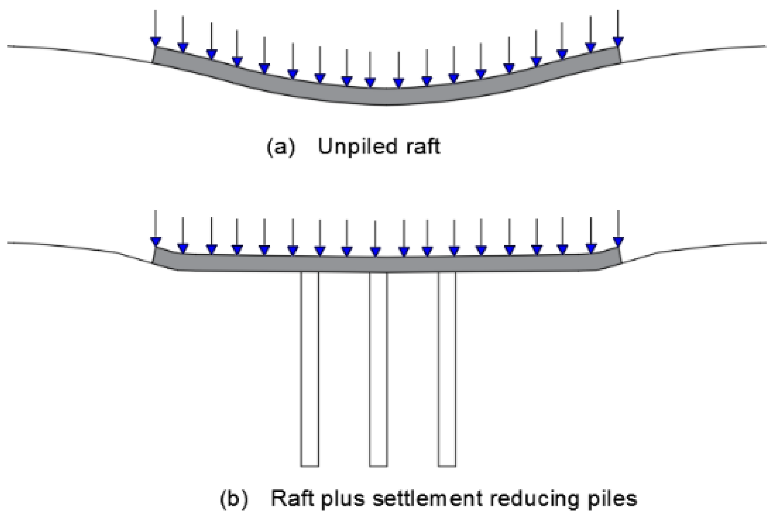
Figure 1. Piles required to reduce differential settlement.
Applsci 13 00546 g001
Figure 2. Pile arrangement and raft dimensions (in mm).
Applsci 13 00546 g002
Figure 4. Raft models for groups of 2 × 2 piles.
Applsci 13 00546 g004
Figure 5. Assembly parts of the pile.
Applsci 13 00546 g005
Figure 6. 3D drawing of the assembled piled raft model.
Applsci 13 00546 g006
Figure 7. Piled raft model with installed measurement equipment.
Applsci 13 00546 g007
Figure 8. Piled raft model prior to driving it into the soil.
Applsci 13 00546 g008
Figure 9. Piled raft model during its driving into the soil.
Applsci 13 00546 g009
Figure 10. Mobile test box.
Applsci 13 00546 g010
Figure 11. Data logger.
Applsci 13 00546 g011
Figure 12. Digital callipers.
Applsci 13 00546 g012
Figure 13. Load cell with a measuring capacity of 350 kg.
Applsci 13 00546 g013
Figure 14. Miniature force sensor, “DYMH-106/30 kg”.
Applsci 13 00546 g014
Figure 15. Spreader—front view.
Applsci 13 00546 g015
Figure 16. Spreader—side view.
Applsci 13 00546 g016
Figure 18. Raft model 84 × 84 × 10 mm prior to driving it into the soil.
Applsci 13 00546 g018
Figure 19. Load bearing curves for rafts without piles.
Applsci 13 00546 g019
Figure 20. Diagram “force–displacement” of piled raft L/d = 40, e/d = 3.
Applsci 13 00546 g020
Figure 21. Load distribution graph for the group of 4 piles with 40d length at the distance of e = 3d.
Applsci 13 00546 g021
Figure 33. Diagram “force–displacement” for the piled raft L = 40d, e/d = 3;4;5.
Applsci 13 00546 g033
Figure 34. The effect of the group of 2 × 2 piles for piles length L = 40d.
Applsci 13 00546 g034
Figure 35. Settlements of pile groups with length of L = 40d in relation to pile distances at the load of 350 N.
Applsci 13 00546 g035
Figure 36. Settlements of pile groups with length of L = 40d in relation to pile distances at the load of 250 N.
Applsci 13 00546 g036
Figure 37. Settlements of pile groups with length of L = 10d in relation to pile distances at the load of 100 N.
Applsci 13 00546 g037
Figure 38. Total portion of the load carried by the piles for same distances and different pile lengths.
Applsci 13 00546 g038
Figure 39. Bearing capacity of piled rafts and rafts without piles for different pile lengths and piles at a distance of 3d.
Applsci 13 00546 g039
Figure 40. Load bearing capacity of piled rafts and rafts without piles for different pile lengths and piles at a distance of 4d.
Applsci 13 00546 g040
Figure 41. Load bearing capacity of piled rafts and rafts without piles for different pile lengths and piles at a distance of 5d.
Applsci 13 00546 g041
Disclaimer/Publisher’s Note: The statements, opinions and data contained in all publications are solely those of the individual author(s) and contributor(s) and not of MDPI and/or the editor(s). MDPI and/or the editor(s) disclaim responsibility for any injury to people or property resulting from any ideas, methods, instructions or products referred to in the content.