Abstract
The Measurement-While-Drilling (MWD) system, composed of a tri-axial magnetometer and a tri-axial accelerometer, is widely used in the Horizontal Directional Drilling machine in coal mines. This system can provide attitude information of each measuring point in the borehole, which will eventually allow the trajectory of the borehole to be drawn. The attitude information, however, showed a low-level accuracy, due to the sensor’s imperfection and mounting errors. The accuracy worsened when low-cost sensors were employed, as they had higher random noise. Therefore, an exploration of ways to eliminate the sensor imperfection and mounting tolerance as well as to suppress the noise is needed. In this paper, a feasible calibration approach was designed to address these issues. This new approach combined three foundational calibration algorithms, including the ellipsoidal fitting method, the planar fitting method, and the inner product invariance method. The traditional ellipsoidal fitting method and planar fitting method were optimized by using the recursive least square criterion and omitting the steps of sample data acquisition, respectively. In addition, the noise suppression method was involved in our approach to improve the calibration accuracy. The numerical simulation results showed that the number of sampling points decreased significantly, but the accuracy of the azimuthal angle and the pitch angle fully met the engineering requirements. The experimental results showed that the pitch angle error was reduced by less than 0.5°, and the azimuth error was also reduced by less than 2.5°. It should be noted that this new approach could be implemented without the help of other expensive auxiliary equipment.
1. Introduction
With extensive application of nearly-horizontal drilling equipment in the coal mining industry, in for example the gas drainage, the water detection, and the coal bed methane exploitation, directional drilling technology has made a great development [1,2,3,4,5,6]. In particular, the equipment used for monitoring the state of the borehole and measuring the trajectory of the borehole have been an intensive research subject in recent decades [1]. The core of underground in-seam directional drilling technology is exactly this equipment, namely the Measurement-While-Drilling (MWD) instrument. Many scholars have focused on improving the detection function of this instrument to avoid coal mine disasters, such as measuring vibrations to prevent rock bursts [2,3,4,5], while ignoring the measurement of the borehole trajectory itself. Rebuilding the borehole trajectory aims to guide the bottom drilling tool along a predefined line, which is very important during the drilling process [7]. Thus, it is very necessary to accurately draw the borehole trajectory with the MWD instrument [6,7,8,9]. The borehole trajectory is geometrically regarded as a 3D curve, which is calculated from the attitude information of the borehole and the length of the drill pipe. Actually, the MWD instrument, installed in the nonmagnetic drill collar behind the screw motor, can provide the attitude information [8,9,10], such as the azimuthal angle, the pitch angle, and the tool-face angle.
This attitude information is mainly solved by the output of one tri-axial accelerometer and one tri-axial magnetometer mounted in the carrier platform of the MWD instrument [11]. Ideally, the tri-axial accelerometer and the tri-axial magnetometer are mathematically considered as two standard Cartesian coordinate frames, and the platform is considered another. These frames form a conceptual sensor model. However, many kinds of errors exist in these tri-axial sensors, such as the null-bias, the sensitivity error, and the non-orthogonal error, etc. [12]. In addition, the misalignment error also exists between the three coordinate frames. Iuri, Valérie, and Long et al. [13,14,15,16,17,18] have fully analyzed the sources of these errors and unified the errors into an error model with 12 parameters. Furthermore, the random noise of the sensor should be taken into account as well during the calibration process and the measurement process [17].
The above descriptions indicate that these errors must be eliminated appropriately for the gaining of the attitude information from the MWD instrument. The counterparts have acknowledged that the error elimination is contingent upon the deployment of the calibration algorithms [13,14,15,16,17,18,19,20,21,22,23]. However, they ignored the method of obtaining the sampled data. For example, Iuri [13] determined all the error parameters of a tri-axial accelerometer by matching the output vector with the gravity acceleration; however, this method has a restrictive condition of knowing the reference of the acceleration vector. Moreover, some expensive instruments were employed to aid calibration, such as the Magnetic Shielding Room [15]. Based on the same theory, Valérie et al. [14,15,16] presented and elaborated an approach, the ellipsoid fitting method, for a stand-alone sensor triplet. Long et al. [18] proposed a fast calibration method specific for a spinning projectile based on the ellipsoid fitting method. Yang et al. [19] improved the ellipsoid fitting method with a truncated singular value decomposition method to enhance the success rate of calibration. It is notable that the above-mentioned studies have an underlying assumption: that is, the axes of the sensor triplet are aligned with the axes of the carrier platform. However, the phenomenon will never happen in practice. Moreover, the magnitude of sample data used in the ellipsoid fitting method is not taken into consideration. Seong-hoon [24] unintentionally took into account the shell or carrier of accelerometer during error estimation process by placing the sensor at six different tilt angles. Similarly, Zhang [25], Fang [26], and Hanak [27] drew on a combination of the ellipsoid fitting method and the multi-position method to solve the problem. However, all the multi-position methods require an extra device to provide a reference position and are unsuited to the MWD instrument. In addition, both Yang [28] and Kok [29] found that introducing the relationship between the gravitational acceleration and the geomagnetic field may help to eliminate the problem. Li [30,31] and Salehi [32] exploited the relationship and proposed a cross product method and a dot product method, respectively. However, they still do not take a carrier platform into the calibration approach for a multi-sensor model. To fill these gaps, our study should address the following two questions:
- (1)
- How to align the coordinate frames of all the sensor triplets with the coordinate frame of a carrier platform in the MWD instrument?
- (2)
- Can the new calibration approach be effectively used to eliminate the measuring errors without the use of prior knowledge about the vector field?
Our study designed a calibration approach in which three underlying algorithms—the ellipsoidal fitting (EF) method, the planar fitting (PF) method and the inner product invariance (IPI) method were combined as a new method to develop the measuring accuracy and eliminate the systemic errors in the MWD instrument. Specifically, in our calibration approach, the traditional EF method and PF method were optimized to cut down the size of sample data. This new calibration approach was simulated to compare the accuracy of the data under different conditions in MATALB. This new approach was also applied actually to calibrate the self-designed MWD prototype. The parameters obtained from the calibration approach were verified by a tri-axial non-magnetic turntable.
2. Materials and Methods
2.1. Sensor Model and Error Model
The sensor model of the magnetometer-based MWD instrument is mathematically considered as three sets of a coordinate frame: the coordinate frame of carrier platform (xbybzb, abbr. car frame, and the index is b), the coordinate frame of the tri-axial accelerometer (xayaza, abbr. acc frame, and the index is a) and the coordinate frame of the tri-axial magnetometer (xmymzm, abbr. mag frame, and the index is m). By default, the car frame xbybzb is thought of as a standard Cartesian coordinate frame. However, the other two sensor coordinate frames are all non-standard (the axes are non-orthogonal and unequal to each other). The situation is rendered in Figure 1. Moreover, the index so denotes a mirror coordinate frame of a sensor triplet which is a standard Cartesian coordinate frame in any direction, such as xaoyaozao or xmoymozmo for tri-axial accelerometer or tri-axial magnetometer, respectively. After the matrix rotation transformation, the mirror coordinate frames (xaoyaozao or xmoymozmo) would be aligned with the car frame (xbybzb).
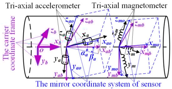
Figure 1.
The schematic diagram of coordinate frame for MWD instrument.
The attitude information (i.e., azimuthal angle ψ, pitch angle θ and tool-face angle φ) for this sensor model is the three Euler angles which refer to the transformation from the geographic coordinate frame (i.e., North-East-Down coordinate frame; abbr. NED frame) to the car frame. The detailed calculation of these angles has been given by Xu.T in [33].
Based on the sensor model, the error model of these sensors can be formulated as the equation of Equation (1). As shown in this equation, the vector represents one element in the data set of raw measurements Dk{ = (, , )T|n = 1, …, N}. The vector represents the local field vector in the car frame, = (,,)T. In the equation, the superscripts s and b represent the categories of the coordinate frame, in which s denotes the coordinate frame of the sensor and b denotes the car frame. Similarly, the subscript k denotes the type of vector (i.e., k = a or k = m denotes the acceleration vector of gravity or the vector geomagnetic field), and the resulting physical quantities and in metric units denote the nth measured value of the vector and in their respective coordinate frame.
where is a 3 × 3 matrix which aggregates all errors with a linear transformation, bk is a 3 × 1 bias vector which includes all the additive errors and εk is Gaussian white noise. Although it is impractical to separately consider the error sources [31], the error matrix could still be divided into the internal component and the external component, according to the error sources, which can be formulated as the following equation.
where represents the error parts outside a sensor triplet, and represents that inside. Then, the error model for a MWD instrument can be separately rewritten as Equation (3).
where, k (k = a or k = m) denotes the type of vector. The and conform to two respective criteria, namely ‖‖ = ‖G‖ and ‖‖ = ‖M‖. G and M are the vectors of the Earth’s gravitational field and magnetic field in the NED frame, and ‖·‖ is the Euclidean norm.
By algebraic transformation, a calibration model could be acquired as Equation (4).
2.2. Basic Calibration Algorithm
2.2.1. Ellipsoidal Fitting Method (EF)
According to the existing literature [14], the data points in the set Dk, measured by a sensor triplet, are to lie on the surface of an ellipsoid. Yet, the data points of the local field vector , in the car frame in any direction, are to lie on the surface of a sphere whose radius is equal to the field strength. Then, the EF method, one kind of a scalar calibration method, makes use of the fact that the strength of the local field vector is a constant. It can determine all the error parameters of a single sensor triplet. With these error parameters, the data points on the surface of a sphere are mapped to the data points on the surface of an ellipsoid through translation, skewness and scaling. As discussed in [14], the data set Dk obtained from rotating a sensor triplet in any direction could meet the equation of Equation (5), according to the principle that the norm of the data points in Dk is equal to the strength of the field vector.
where Q = T, and H is the Euclidean norm of the field vector. When the errors of sensor are small, the matrix Q is strictly diagonally dominant [34]. The Gaussian white noise is ignored here. After algebraic operation, Equation (5) could be rewritten as Equation (6), which is shown below.
where Q′ = Q/(‖H‖2 − Qbk), and p′ = −2Q′. Then, a parameter σ is introduced to simplify the equation of Q’, namely σ = 1/(‖H‖2 − Qbk). When Equation (6) is expanded, a linear equation can be got, as shown in Equation (7).
The corresponding equation is shown in Equation (8). Once the coefficient vector β = (a, b, c, d, e, f, g, h, i)T is figured out, the matrix Q′ and p′ can be derived by the corresponding expression.
Furthermore, the matrix Q and bias vector bk can also be solved out by the equations as shown below.
An overdetermined linear equation set is established when the data points in Dk are substituted into Equation (7) on the condition of N >> 12. The traditional solving method of the overdetermined equations is just the least squares criterion. The resulting equation is shown in Equation (10).
where β denotes the coefficient vector of Equation (7), is the matrix of the raw data set Dk and its dimension is N × 9. In is a unit vector of N × 1 dimension.
Then, the calibration matrix is derived by the eigenvalue decomposition method, (Q = VDVT). The result is stated in Equation (11), in which V is the eigenvector of Q, and D is a diagonal matrix with the eigenvalue of Q.
It is notable that the matrix has infinite solutions when the Q is decomposed by Equation (11). This decomposition procedure can be algebraically expressed as Equation (12).
where R is an arbitrary orthogonal matrix. Geometrically, this phenomenon implies that a calibrated sensor coordinate frame by EF method could rotate to any direction, and any one of the resulting coordinate frames can be considered as a mirror coordinate frame of the original sensor coordinate frame. Thus, the result of matrix decomposition is , not , and = .
Li, X. et al. [31] had classified the deviation matrix R in direction as a misalignment or a rotation error. Obviously, the coordinate frame of a sensor triplet can be converted into a Cartesian coordinate frame under the calibration of the EF method. The measuring points will lie on the surface of a sphere after this calibration. Yet, the direction of this sphere is uncertain, and the radius of the sphere equals to the magnitude of the field vector [29].
2.2.2. Plane Fitting Method (PF)
The coordinate frame of the two sensor triplets have been regulated to its respective mirror coordinate frame in the first part of this section. However, the problem of the direction of the mirror coordinate frame still exists. In this part, this problem will be solved by aligning with the car frame. Včelák, J. [35,36] had proposed a similar method to solve the problem but did not given the detailed equations. In this paper, the method is further deduced and refined.
It is assumed that the Euler angles (αk, βk, γk) are used to depict misalignment between the mirror coordinate frame (xkoykozko) and the car frame (xbybzb). As well, two sets of raw data of the measured points (Dk−x and Dk−z) can be sampled from the sensors of the MWD instrument by rotating around the two axes (xb-axis and zb-axis) of the car frame, respectively. The outputs of the sensors mounted along the xb-axis and the zb-axis have a sinewave form, when they are calibrated to its mirror coordinate frame by the EF method, although they will be constant in the car frame. This phenomenon had been depicted by Včelák, J. in [36]. The outputs of the other sensors, when they are calibrated to the car frame, will form two planar circles which will be perpendicular to xb-axis or zb-axis, respectively. Based on these phenomenon, the equations can be established on the principle of the direction cosine matrix (DCM), as depicted as follows:
where = (,,)T is the output vector in its mirror coordinate frame (xkoykozko) and and are the components of Earth’s field vector along the two axes (xb-axis and zb-axis) of the car frame. When the data points in the dataset Dk−x are calibrated firstly by the EF method and then substituted into Equation (13), Equation (13a) will be established, and the component will be considered as a constant (constx). In the same way, when the data points in the dataset Dk−z are operated and substituted into Equation (13), Equation (13b) will be established, and the component will also be a constant (constz). If the number of measuring points in the two datasets is large enough, there will be two overdetermined equations listed. The two equations can also be solved by the least squares criterion. During the solution process, six parameters, Akx,Bkx,Ckx, and Akz,Bkz,Ckz, are introduced, and the equations can be rewritten as followd.
Then the misalignment angles can be calculated with the tangent formula, which is shown in the following equations.
Note that the dataset Dk−z and Equation (15) are only used for solving γk, and the calculation of both αk and βk requires the value of γk. Thus, this feature may be utilized to reduce calibration steps. In addition, if the axis around which the carrier platform is rotated, such as the xb-axis and the zb-axis, parallelize to its measured vector, all of the measuring points will shrink into a point.
In a word, the PF method could completely determine the misalignment between any mirror coordinate frame of a sensor triplet and its car frame, and the calibration equation is shown as follows.
2.2.3. Inner Product Invariance Method (IPI)
As we know, the inner product of any two vectors does not change along with their transformation from one coordinate frame to another. This principle can also be employed to identify the error parameters between two sensor triplets of different kinds of vector. That is to say, an unknown coordinate frame can be calibrated by another standard coordinate frame. In this paper, the acc frame would be calibrated first to coincide with the car frame; then the mag frame will be post-calibrated by the calibrated acc frame, to be consistent with the car frame.
It is assumed that a calibrated vector = (, , )T of the accelerometer is in the car frame, and another vector = (, , )T is the raw output of a tri-axial magnetometer, which is in its own sensor coordinate frame. The inner product of the two vectors can be expressed as the following equation, according to the principle.
where ξ is the co-angle of the earth’s magnetic dip and and bm are the undetermined coefficient matrix and bias vector for the tri-axial magnetometer. When Equation (19) is expanded with the two vectors, ( and ), and the data of the measuring points in the two datasets ( and Dm) are substituted in Equation (19), an overdetermined equation will be established. The solving method is the same as before, and the result needs to be restructured to get the matrix and bias vector. The attention of this method in the process of applying to Attitude and Heading Reference System would not be repeated here, because they were clearly discussed in [31].
2.3. Improvement of the Calibration Methods
2.3.1. Recursive Least Square Method (RLS)
The raw data of N measuring points for the dataset Dk should be collected in advance, when the EF method is used to get the error parameters. If N is small enough, the calibration method is undoubtedly efficient, premised on getting the right error parameters. In this section, an improved method of direct least square method is introduced to reduce the number of data required by the EF method. The detailed equation derivation is shown below.
Based on Equation (10), the equation Pn = (T)−1 is assumed and is then derived further according to Woodbury matrix identity, as shown below.
where gn = Pn−1T(1 + Pn−1 T)−1. Then, Equation (10) will be decomposed and rewritten on the condition that βn is presumed to be an estimated coefficient vector from the sensor data of the nth times. The result is shown in Equation (21), where the equation gn = Pn−1T(1 + Pn−1 T)−1 = Pn T can be solved out.
The operation steps of the improved method are shown in the following list.
- (1)
- Initialize the coefficient vector β0 and the covariance matrix P0.
- (2)
- Gather the raw data of the nth measuring point, namely = (, , )T.
- (3)
- Calculate the gn and Pn according to Equation (20).
- (4)
- Calculate the new coefficient vector βn according to Equation (21).
- (5)
- Judge the posteriori error ‖en‖, until it meets the inequality ‖en‖ = ‖in − βn‖≤ εstop, then stop the iteration; otherwise, return to step (2). Here, the restriction value of εstop is an empirical value. The method flow chart is shown in Figure 2.
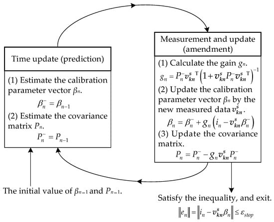 Figure 2. The flowchart of recursive least squares criterion.
All the methods that use the least squares criterion to determine the coefficients in equation can be optimized by the recursive method. The purpose is to reduce the number of the sampling points, such as the EF method and the PF method. However, if the number of samples is fixed, the advantage of recursive least squares criterion will disappear.
2.3.2. Optimization of Plane Fitting Method
There is a noteworthy phenomenon that the calculation of the angle γk of deviation in Equation (16) is only related to the dataset Dk−z, and not to Dk−x. Thus, a theoretical hypothesis about the attitude information solution of the MWD instrument was presented, that the calculation of azimuthal angle ψ and pitch angle θ are independent of the angle γk. In this case, the step of gathering dataset Dk−z can be omitted and the PF method is also simplified.
This hypothesis can be proved mathematically on the following precondition. Firstly, the output of the tri-axial accelerometer needs to be calibrated to its own mirror coordinate frame in advance by the EF method. The output vector can be expressed as = (,,)T. Secondly, the parameters (Aax, Bax, Cax) related to the misalignment error matrix have been solved by the PF method, on the condition that the dataset Da−x is prepared. After calibration with the IPI method, the mirror coordinate frame of the tri-axial magnetometer has the same misalignment as the tri-axial accelerometer to the car frame.
Then, the irrelevance between the misalignment angle γk and the calculation of the attitude information will be exhibited by the following equations.
- (1)
- The solving equation of the pitch angle θ is derived with the vector = (,,)T of the gravity vector G in the mirror coordinate frame.
- (2)
- The calculation equation of the azimuthal angle ψ can be rewritten as Equation (23).
It could be concluded from the two equations above that the hypothesis is true. The calculation of azimuthal angle ψ and pitch angle θ for the MWD instrument is indeed only related to the sensor output and the sampling data set Dk−x, but not to the misalignment angle γk or the data set Dk−z [37].
It is worth mentioned that this hypothesis just meets the feature of the MWD instrument. Because it is impossible to find the physical axes (the yb-axis and zb-axis) on this cylindrical carrier platform, it is also infeasible to rotate around the zb-axis and gather the data set Dk−z.
It should be emphasized here that the exact value of the misalignment error angle (αa, βa, γa) cannot be obtained by the specific calculation without the data set Da−z. However, according to the hypothesis, the value of γa could be set to 0 artificially. Then, the misalignment angle (αa, βa, 0) can be calculated according to Equation (14). From a geometric point of view, the carrier platform of the MWD instrument is a cylinder, and once the xb-axis is fixed, the yb-axis and zb-axis would be the axes of any orthogonal coordinate frame in the plane perpendicular to the xb-axis. Therefore, when the angle γa = 0, the car frame xbybzb would be aligned to the calibrated tri-axial accelerometer coordinate frame xabyabzab.
2.4. Design of the Calibration Approach
The calibration approach was designed by assembling the sub-methods mentioned in the above sections to calibrate the sensor model. The operation process of this approach consisted of the sampling datasets (Da, Dm, Da−x) collection and the calibration methods implementation. As shown in Figure 3, the calibration approach contributed to the lower magnetic interference and the smaller sample data size.
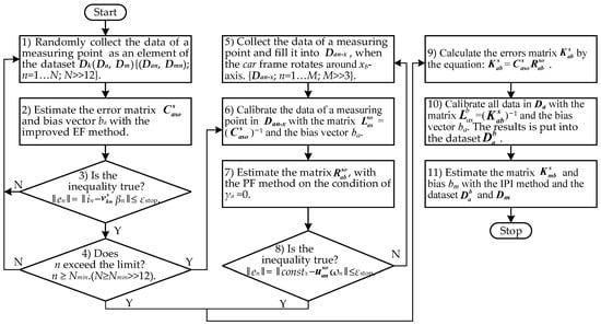
Figure 3.
The operation flow chart of the calibration approach.
In Figure 3, the method of getting the sample data can be regarded as a key point of the calibration approach. The sample datasets Dk were gathered by rotating the MWD instrument in different directions in an absolute interference-free environment, and these datasets finally formed as an ellipsoidal surface. In addition, the sample datasets Da−s formed a planar ellipse, which were collected by rotating around the xb-axis of the MWD instrument. All of these datasets were used to cooperate with the improved EF method and the simplified PF method to get the more accurate error parameters.
2.5. The Collecting Method for the Sample Data
This section describes the collection of the data points (the datasets Dk and the dataset Da−x). The error parameters, in a tri-axial accelerometer and a tri-axial magnetometer, are provided in Table 1 in advance. Furthermore, the two constant vectors (the gravitational vector and the geomagnetic vector) can be presented as G = (0, 0, 1) and M = (29.4, 0, 45.3), respectively, in the NED frame, after an online search [38].

Table 1.
The assumed error parameters for the sensor model of the MWD instrument.
The method of collecting the data sets Dk comes from a further extension of the equal- angle criteria [37]. It aims to simulate the process of the MWD instrument measuring data at different attitudes. Firstly, the error-free sampling points were gathered to simulate the output of the tri-axial accelerometer and the tri-axial magnetometer in the car frame. These sampling points were evenly distributed on the spherical surface which is formed by the tri-axial components of the two constant vectors (G and M) in the car frame with any attitude. The method of collecting these error-free sampling points was implemented by the following steps.
- Artificially fix a pitch angle sequence [−90°, 90°, −45°, 45°, 0°] in the range of [−90°, 90°].
- Pick out a value in turn from the angle sequence in step 1 as a selected pitch angle θi.
- Calculate an azimuthal angel sequence based on the value of the selected pitch angle θi, according to Equation (24), where nψi is the total number of angles in the azimuth sequence.
- Pick out a value in turn from the azimuthal angel sequence in step 3 as a selected azimuthal angel ψij.
- Five values are randomly given as a tool-face angle sequence in the range of [0°, 360°].
- Pick out a value in turn from the tool-face angle sequence in step 5, as a selected tool-face angel φk. Then, the selected attitude angles (ψij, θi, φk) are determined.
- Solve the tri-axial components of the two constant vectors (G and M) in the car frame by the direction cosine matrix which has been built with the selected attitudes angle above. These tri-axial components are exactly the datasets of error-free data points.
Moreover, as shown in Figure 4, the selected attitude angles are commonly referred as the Euler angles.
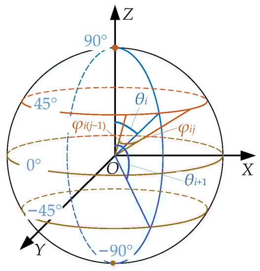
Figure 4.
Schematic diagram for distribution rule.
Secondly, these error-free data points were distorted with the error parameters listed in Table 1. These newly gathered data points after the distortion were considered as the output data of the MWD instrument. Then, 150 sets of output data were collected as the datasets Dk (Da, Dm), which are shown in Figure 5a,b. A part of data in the datasets Dk, following the rule of pitch angle θ = −45°, were extracted as the planar data set Dk−x (Da−x, Dm−x). Figure 5c,d show that 40 sets of data in Dk−x were extracted in total. It is obvious that if the dataset Da−x can be extracted from the dataset Da, the collection step (the fifth step in Figure 3) can be omitted; therefore, the calibration approach is further simplified.
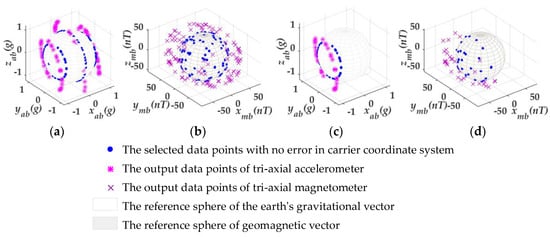
Figure 5.
The collected sampling datasets. (a,b) 150 sets of sampling points to simulate the output of tri-axial accelerometer and tri-axial magnetometer without noise. (c,d) 40 sets of sampling points following the rule of pitch angle θ = −45° without noise.
In addition, the random noise conforming to the Gaussian distribution N (0, σ2) was added in the Dk, for making the collected data closer to the real data measured by the MWD instrument. The noise variance σ2 is 0.000139 and 0, 0.00096, respectively, at the frequency of 1 Hz, according to the datasheet of the tri-axial accelerometer and the tri-axial magnetometer used in the self-designed MWD instrument.
It should be emphasized here that all of the collected data points were rotating around the xb-axis as seen from Figure 5, which is the real axis of MWD instrument. To sum up, the collecting method can be used to collect data in the real MWD instrument.
3. Analysis and Discussion of the Calibration Approach
The calibration approach was numerically simulated by the MATLAB program. The collected data in Figure 5 are used to verify the feasibility of the calibration approach. The other 15 sets of attitude data were randomly given to test the accuracy of this approach. The simulation also compared the calibration results with and without random noise.
Firstly, the collected data and the testing date (15 sets of random attitude data) did not contain random noise. The calibration approach (in Figure 3) was examined by the collected data, on the condition of the given values of γa. Table 2 lists the estimated error matrixes and biases based on the condition of γa = 0° and γa = 5°. By comparing Table 1 and Table 2, we found that, the bias bk (ba, bm) and the diagonal elements of the error matrixes ( and ) were fully determined by the calibration approach. The non-diagonal elements of the error matrixes ( and ), however, were not.
Table 2.
The resolved error matrixes and biases by the calibration approach.
After that, the testing data (15 sets of given attitude data) were employed to verify the accuracy of the estimated error parameters. The test results are shown in Figure 6, and five sets of them were picked out and listed in Table 3.
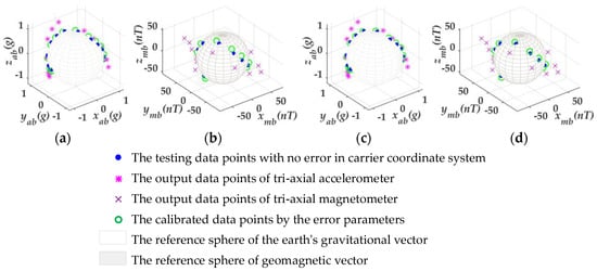
Figure 6.
The test results on the condition of γa = 0° and γa = 5°. (a,b) The test results of tri-axial accelerometer and tri- axial magnetometer, respectively, on the condition of γa = 0°. (c,d) The test results on the condition of γa = 5°.
Table 3.
The comparison of attitude angles before and after calibration.
Figure 6a,b show the test results of the tri-axial accelerometer and tri-axial magnetometer, respectively, on the condition of γa = 0° for the MWD instrument. Figure 6c,d put forward the test results on the condition of γa = 5°. As shown in Figure 6, a fixed deviation in the direction of around the xb-axis existed between the calibrated data points and the given data points, although the two types of the data points should coincide with each other. This argument is further illustrated in Table 3 by the value of the testing attitude angles. In Table 3, the values of the tool-face angle φ were different, but the calculation of the pitch angle θ and azimuthal angle ψ would not be affected by different values of γa in the calibration approach. However, this case can be perfectly compatible with the MWD instrument, because the drawing of the borehole trajectory does not need the participation of the tool-face angle φ.
In addition, it should be mentioned that a total of 77 sets of data points (N = 77) were used to estimate the error parameters when using the improved EF method on the two conditions of εstop = 10−9 and Nmin = 70.
Secondly, a random noise was added in the collected data and the testing data. Thus, a noise suppression method was also needed. This noise suppression method was realized by obtaining average values of the multiple samples. That is, the MWD instrument continuously sampled several times and outputted the mean of these sampling data when this instrument is stable at a certain attitude. This method was used to improve the calibration approach by changing the numbers of sampling times from a single time to several times at each attitude. Of course, the sampling times of the MWD instrument were also transformed from a single to several times in actual measurement. In the following simulation, the estimated results, by the calibration approach with the noise suppression method and without the suppression method, are compared in Table 4 on the same condition of γa = 0°. The number of sampling times during the collection of the datasets Dk was set as 16 times at each attitude in the improved calibration approach. Then, the collection of the 15 sets of a given attitude also employed this noise suppression method by increasing the number of sampling times from one to eight times at each attitude, and five sets of them are shown in Table 5. In this Table, the calibrated results after the suppressed noise method and non-suppressed noise method were compared. Therefore, this noise suppression method is effective.
Table 4.
The solved error matrixes and biases on the condition of adding the random noise.
Table 5.
The comparison of attitude angles calculation with noise suppression and without suppression.
It should be stated that such a setting of the sampling times not only meets the operational requirements of the MWD instrument, but also facilitates MCU programming. We also emphasize that if the Nmin is set as 90 and εstop is set as 10−4, the number of sampling data points may be decreased to 95. This number (less than the total number 150) indicates that the improved EF method is more effective than the original one.
Figure 7, which shows the comparison of the deviation of the 15 sets of data in three cases, gives us a clear description of the improved calibration approach. These three cases are divided according to the different number of sampling times in the noise suppression method. The three cases are represented by C, D and E, respectively.
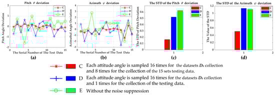
Figure 7.
The comparison diagram of attitude deviation in the three cases. (a,b) Attitude deviation after the calibration in the three cases. (c,d) The STD of the attitude deviation.
In case C, we collected samples 16 times continuously at each attitude in the datasets Dk collection; meanwhile, we collected the other samples eight times continuously at each attitude in the 15 sets of testing data.
In case D, we collected samples at the same times as in the case of C at each attitude in the datasets Dk collection, but we abandoned the noise suppression method in the collection of the 15 sets of testing data.
In case E, we abandoned the noise suppression method in the collection of both the datasets Dk and the 15 sets of testing data.
Figure 7a,b are the diagrams of deviations between the calibrated attitude angles and the given attitude angles. Figure 7c,d are the diagrams of the standard deviation (abbr. STD) for the corresponding deviation. Figure 7a is the pitch angle deviation and Figure 7b is the azimuthal angle deviation. Figure 7 shows that the case C is optimal and can be applied to the real MWD instrument.
4. The Experimental Verification
4.1. The Hardware Design for MWD Instrument
Based on this sensor model (Figure 1), a prototype of a MWD instrument was developed, and the schematic block diagram of this instrument is presented in Figure 8a. This prototype consisted of three electronic subsystems: a sensor subsystem, memory subsystem and control subsystem. All of these subsystems were mounted on an aluminum groove and inserted in a beryllium copper pipe, as shown in Figure 8b.
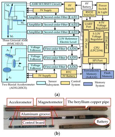
Figure 8.
The figures of the self-designed MWD tool. (a) The schematic block diagram of the MWD instrument; (b) The prototype photo of the MWD instrument.
In the sensor subsystem, three single-axis AMR sensors (HMC1021Z) perpendicular to each other were mounted on one side of the groove, and two dual-axis accelerometers (ADXL203CE) were mounted on other side in the same way. Beyond that, six A/D converters were also equipped for signal digitization with the help of a signal filter (three first-order filters and three second-order filters). In the control subsystem, the core used the minimum system of LPC2194 ARM, which is provided by NXP Semiconductors.
The entire system was powered by an 8 V Ni-MH battery, and this battery voltage was adjusted into 3.3 V and 5 V for the CPU core board and peripheral circuit, respectively, by a voltage regulator. The memory subsystem, including a ferroelectric memory and flash memory, undertook the storage of calibration parameters and measurement data for special purposes.
It should be emphasized that the precision of the output signal of AMR sensor falls easily, and even the direction of its sensitive axis may also reset or reverse. Thus, a high current flipping circuit (AMR SET/RESET circuit) is needed to contribute to each AMR sensor for eliminating magnetic history and restoring high sensitivity [39], on the basis of the datasheet [40].
The schematic diagrams of the signal conditioning circuit of HMC1021Z and the matched SET/RESET circuit are shown in Figure 9. The steps for accurate measurement with the AMR sensor are listed as follows, according to the datasheet.
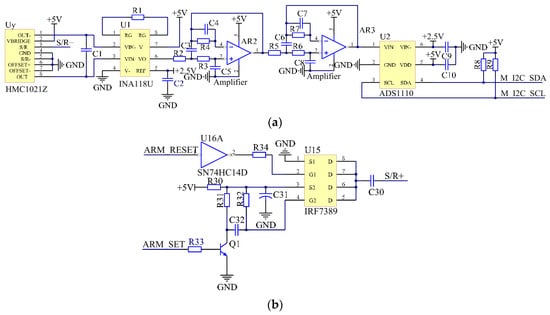
Figure 9.
Partial circuit schematic diagram of HMC1021Z. (a) Schematic diagram of the signal conditioning circuit. (b) Schematic diagram of the designed SET/RESET circuit.
- (1)
- Apply a positive current pulse to S/R+ pin of the AMR sensors with the SET/RESET circuit, and then read the measured value Vset from the corresponding A/D converter.
- (2)
- Apply a negative current pulse and read the measured value Vreset in the same way.
- (3)
- Calculate the actual value Vout, according to the equation Vout = (Vset − Vreset)/2.
However, the output signal of AMR sensor did not respond in time when a current pulse was forced on the S/R+ pin. At the same time, the amplitude of this output decreased regularly with time. This phenomenon can be verified by measuring the amplitude of the signal (Vset or Vreset) at the input pin of A/D converter, which is shown in Figure 10. There are two reasons for the response delay. One is the delay of the signal conditioning circuit, and the other is the delay of the AMR sensor. In addition, the main reason for the decrease of the output is the loss of the sensitivity of the AMR sensor over time.
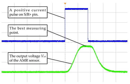
Figure 10.
Voltage curve diagram of the signal from HMC1021Z after a positive current pulse.
Therefore, the CPU must wait for a certain time interval before starting the A/D converter to sample when sending a current pulse, so that the A/D converter could sample at a best sensitivity point. The time interval is generally 200~500 ms, and the best choice is 200 ms for the circuit shown in Figure 9.
4.2. Experimental Process and Result Analysis
The whole calibration was performed in a laboratory without magnetic interference. In this process, the self-designed MWD instrument needed to be fixed on a tri-axial non-magnetic turntable which could provide reference attitude. We read the attitude angles both from the mechanical encoders of the non-magnetic turntable and the output of the self-designed MWD instrument. Then, we operated the non-magnetic turntable using the method mentioned in Section 2.5 and collected the output data of the MWD instrument at the specified attitude angles. The datasets Dk (N = 150) were obtained; of course, the data set Da−x (N = 40) could be also extracted from Dk. By the calibration approach shown in Figure 3, the calibration matrix Lk and bias vector bk were determined as shown in Table 6. After that, five sets of random attitude angles were chosen to check the accuracy of the parameters in Table 6. From the results, shown in Table 7, we found that the proposed calibration approach could completely calibrate the system error of MWD instrument but could not eliminate the influence of the random noise; the noise of the sensor could only be suppressed, not eliminated.
Table 6.
The calibration parameters determined by the method.
Table 7.
Test verification of the calibration strategy.
In order to further verify the authenticity of the parameters in Table 6, a field test was conducted in a coal mine to draw the borehole trajectory map. The mathematical method for drawing trajectory is called the balanced tangent method which mainly depends on the attitude angles (pitch angle θ and azimuthal angle ψ) at the measuring point of each drill pipe. Before the test, a pre-designed trajectory should be prepared. Then, we moved the MWD instrument along the prepared path and sampled at each measuring point at the same time. Finally, the measured data were uploaded to the software for drawing the trajectory map, which is shown in Figure 11 in the form of the upper-lower deviations and the left-right deviations. This deviations refer to the distance that the actual drilling trajectory deviates from the straight line of the initial direction (the attitude information of the orifice). The upper-lower trajectory deviations are mainly related to the difference between the pitch angle θ at each measuring point and the pitch angle at the orifice position, and the left-right trajectory deviations are mainly related to the difference between the azimuthal angle ψ at each measuring point and the azimuthal angle at the orifice position. With this trajectory showing method, we can intuitively see how far the actual drilling trajectory deviates from the direction of the orifice. In Figure 11, the black line is the prepared path, and the black dots on the line are the points with known attitude information. The other lines are the trajectories drawn with the data uploaded from the self-designed MWD instrument. We can clearly see that the trajectory drawn with the data from the calibrated MWD instrument roughly coincides with the prepared path, and the trajectory from the un-calibrated MWD instrument deviates far from the prepared one.
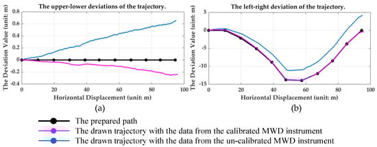
Figure 11.
The 2D contrast maps of the trajectory deviations. (a) Map of the upper-lower deviation of the three sets of trajectory data. (b) Map of the left-right deviations of the three sets of trajectory data.
We found that the tri-axial non-magnetic turntable is not necessary from the whole experiment. But if we do not use this auxiliary equipment, the data collection steps for the raw datasets Dk and the dataset Da−x need to be conducted separately. Meanwhile, a special bracket is required to help the MWD instrument rotating around the xb axis of the car frame, to ensure the reliability of the dataset Da−x.
5. Conclusions
The purpose of this study was to design an approach to calibrate the MWD instrument to improve the accuracy of drilling trajectory drawing, in order to provide accurate information of the geological context. We found that our new calibration approach solved system errors and suppressed the random noise with fewer data collection stages. Specifically, the recursive least squares criterion was used rather than the direct least squares criterion to reduce the magnitude of sampling data. The optimized PF method was designed to simplify the procedures of data collection. To sum up, the new calibration approach well matched the operating characteristics of the self-designed MWD instrument. This new calibration approach is validated by the simulating program with MATLAB and the practical application on the self-designed MWD instrument. Both show that the accuracy well meets the engineering requirements.
Author Contributions
Software, K.L.; Validation, L.L. and T.L.; Writing—review & editing, Z.L.; Supervision, J.S. All authors have read and agreed to the published version of the manuscript.
Funding
This research was funded by SHANXI KEY RESEARCH AND DEVELOPMENT PROJECTS (Research and application of key technologies of 15,000 type intelligent directional drilling machine for mine gas drainage), grant number 202003D111008.
Institutional Review Board Statement
Not applicable.
Informed Consent Statement
Not applicable.
Conflicts of Interest
The authors declare no conflict of interest.
References
- Shi, Z.J.; Dong, S.N.; Yao, N.P.; Tian, D.Z. The Underground Directional Drilling Technology and Equipment for Kilometer Deep Borehole with MWD in Coalmine. Procedia Earth Planet. Sci. 2011, 3, 17–22. [Google Scholar] [CrossRef]
- Li, C. Automatic Implementation Algorithm of Pressure Relief Drilling Depth Based on an Innovative Monitoring-While-Drilling Method. Sensors 2022, 22, 3234. [Google Scholar]
- Zhang, W.; Li, C.; Jin, J.; Qu, X.; Fan, S. A new monitoring-while-drilling method of large diameter drilling in underground coal mine and their application. Measurement 2020, 173, 108840. [Google Scholar] [CrossRef]
- Rai, P.; Schunnesson, H.; Lindqvist, P.A.; Kumar, U. Measurement-while-drilling technique and its scope in design and prediction of rock blasting. Int. J. Min. Sci. Technol. 2016, 26, 697–705. [Google Scholar] [CrossRef]
- Zhang, W.; Li, C.; Ren, J.; Wu, Z. Measurement and application of vibration signals during pressure relief whole construction using micro seismic system. Measurement 2020, 158, 107696. [Google Scholar] [CrossRef]
- Rai, P.; Schunesson, H.; Lindqvist, P.-A.; Kumar, U. An Overview on Measurement-While-Drilling Technique and its Scope in Excavation Industry (Review). J. Inst. Eng. 2015, 1, 57–66. [Google Scholar]
- Zhang, Y.; Wang, S.; Fang, J. Measurement-While-Drilling Instrument Based on Predigested Inertial Measurement Unit. IEEE Trans. Instrum. Meas. 2012, 61, 3295–3302. [Google Scholar]
- Jurkov, A.S.; Mintchev, M.P. Experimental feasibility of the in drilling alignment method for inertial navigation in measurement-while-drilling. IEEE Trans. Instrum. Meas. 2005, 54, 1997–2006. [Google Scholar] [CrossRef]
- Ju, L.L.; Wang, X.F.; Ma, S.; Wei, C.M. The Algorithm Study of Sensor Compensation in MWD Instrument Based on Genetic Elman Neural Network. In Proceedings of the Third International Symposium on Intelligent Information Technology and Security Informatics, Jinggangshan, China, 2–4 April 2010. [Google Scholar]
- Du, L.; Luo, W.; Lv, H.; Xu, T. Research of measurement while drilling and azimuth correction for horizontal directional drilling. Chin. J. Sci. Instrum. 2007, 2, 236–240. [Google Scholar]
- Gong, X.; Yang, J.; Wang, W. Design of High Accuracy Orientation sensor of MWD. In Proceedings of the International Conference on Electric Information and Control Engineering (ICEICE), Wuhan, China, 15–17 April 2011. [Google Scholar]
- Yu, H.; Ye, L.; Guo, Y.; Suan, S. Effective In-Field Calibration Method for Triaxial Magnetometers based on Local Magnetic Inclination. IEEE Trans. Instrum. Meas 2020, 7, 1–9. [Google Scholar] [CrossRef]
- Frosio, I.; Pedersini, F.; Borghese, N.A. Autocalibration of MEMS Accelerometers. IEEE Trans. Instrum. Meas 2009, 6, 2034–2041. [Google Scholar] [CrossRef]
- Valérie, R.; Muhammad, H.; Gérard, L. Complete Tri-axis Magnetometer Calibration in the Magnetic Domain. J. Sens. 2010, 1, 23–59. [Google Scholar]
- Pan, D.; Li, J.; Jin, C.; Liu, T.; Lin, S.; Li, L. A New Calibration Method for Tri-axial Fluxgate Magnetometer Based on Magnetic Shielding Room. IEEE Trans. Ind. Electron 2020, 5, 67. [Google Scholar]
- Valérie, R.; Muhammad, H.; Gérard, L. New Method for Magnetometers Based Orientation Estimation. In Proceedings of the Position Location and Navigation Symposium (PLANS), Indian Wells, CA, USA, 4–6 June 2010. [Google Scholar]
- Song, Z.G.; Zhang, J.S.; Zhang, X.H.; Xi, X.L. A Calibration Method of Three-Axis Magnetometer with Noise Suppression. IEEE Trans. Magn. 2014, 11, 5011–5015. [Google Scholar]
- Long, D.; Zhang, X.; Wei, X.; Luo, Z.; Cao, J. A Fast Calibration and Compensation Method for Magnetometers in Strap-Down Spinning Projectiles. Sensors 2018, 18, 4157. [Google Scholar] [CrossRef] [PubMed]
- Yang, Z.; Li, B.; Chen, L. Calibration of tri-axis magnetometers using an improved truncated singular value decomposition method. Meas. Sci. Technol. 2018, 29, 125101. [Google Scholar]
- Liu, Y.X.; Li, X.S.; Zhang, X.J.; Feng, Y.B. Novel Calibration Algorithm for a Three-Axis Strap down Magnetometer. Sensors 2014, 14, 8485–8504. [Google Scholar] [CrossRef]
- Kiani, M.; Pourtakdoust, S.H.; Sheikhy, A.A. Consistent calibration of magnetometers for nonlinear attitude determination. Measurement 2015, 73, 180–190. [Google Scholar] [CrossRef]
- Li, T.; Zhang, J.S.; Wang, S.C.; Li, D.Y.; Lv, Z.F.; Jiang, J.J. Calibration of three-axis magnetometers with alternative iteration looping optimization method. Sens. Rev. 2018, 38, 509–516. [Google Scholar] [CrossRef]
- Wu, Y.; Shi, W. On Calibration of Three-axis Magnetometer. IEEE Sens. J. 2015, 15, 6424–6431. [Google Scholar] [CrossRef]
- Won, S.H.P.; Golnaraghi, F. A Triaxial Accelerometer Calibration Method Using a Mathematical Model. IEEE Trans. Instrum. Meas. 2010, 59, 2144–2153. [Google Scholar] [CrossRef]
- Zhang, X.; Chen, G.; Li, J.; Li, J. Calibration of tri-axial MEMS vector field measurement system. IET Sci. Meas. Technol. 2014, 8, 601–609. [Google Scholar]
- Fang, J.; Sun, H.; Cao, J.; Zhang, X.; Tao, Y. A novel calibration method of magnetic compass based on ellipsoid fitting. IEEE Trans. Instrum. Meas. 2011, 60, 2053–2061. [Google Scholar] [CrossRef]
- Hanak, F.C.; Wilson, H.; Gjertsen, M. Assessment of the Validity of MWD Survey Accuracy Following Multistation Analysis. In Proceedings of the SPE/IADC Drilling Conference & Exhibition, London, UK, 17–19 March 2015. [Google Scholar]
- Yang, W.; Fang, B.; Tang, Y.; Qian, J.; Qin, X.; Yao, W. A Robust Inclinometer System with Accurate Calibration of Tilt and Azimuth Angles. IEEE Sensors J. 2013, 13, 2313–2321. [Google Scholar] [CrossRef]
- Kok, M.; Hol, J.; Schön, T.B.; Gustafsson, F.; Luinge, H. Calibration of a magnetometer in combination with inertial sensors. In Proceedings of the 15th International Conference on Information Fusion (FUSION), Singapore, 9–12 July 2012. [Google Scholar]
- Li, W.; Du, Q.; Peng, M. A MEMS Inertial Sensor and AMR Magnetic Sensor Calibration Method. In Proceedings of the 2011 8th International Conference on Information, Communications & Signal Processing (ICICS 2011), Singapore, 13–16 December 2011. [Google Scholar]
- Li, X.; Li, Z. A new calibration method for tri-axial field sensors in strap-down navigation systems. Meas. Sci. Technol. 2012, 23, 1–6. [Google Scholar] [CrossRef]
- Salehi, S.; Mostofi, N.; Bleser, G. A practical in-field magnetometer calibration method for IMUs. In Proceedings of the IROS Workshop on Cognitive Assistive Systems: Closing the Action-Perception Loop, Vila Moura, Algarve, Portugal, 7–12 October 2012. [Google Scholar]
- Xu, T.; Luo, W.; Lu, H.; Qin, L. Design of underground sonde of a directional drilling locator system. Sens. Actuators A 2005, 119, 427–432. [Google Scholar]
- Ortega, J.M.; Rheinboldt, W.C. Iterative Solution of Nonlinear Equations in Several Variables; Academic Press: New York, NY, USA, 1970; Volume 25, pp. 347–380. [Google Scholar]
- Včelák, J.; Ripka, P.; Platil, A.; Kubík, J.; Kašpar, P. Errors of AMR compass and methods of their compensation. Sens. Actuators A 2006, 129, 53–57. [Google Scholar] [CrossRef]
- Včelák, J.; Ripka, P.; Kubik, J.; Platil, A.; Kašpar, P. AMR navigation systems and methods of their calibration. Sens. Actuators A 2005, 123, 122–128. [Google Scholar] [CrossRef]
- Liu, Z.; Song, J. A Low-Cost Calibration Strategy for Measurement-While-Drilling System. IEEE Trans. Ind. Electron. 2018, 65, 3559–3567. [Google Scholar]
- Available online: https://www.ngdc.noaa.gov/geomag/calculators/magcalc.shtml#igrfwmm (accessed on 20 July 2022).
- Hauser, H.; Fulmek, P.L.; Haumer, P.; Vopalensky, M.; Ripka, P. Flipping field and stability in anisotropic magneto resistive sensors. Sens. Actuators A Phys. 2003, 15, 121–125. [Google Scholar] [CrossRef]
- AN213 SET/RESET Function for Magnetic Sensors. Honeywell Application Note. Available online: https://aerospace.honeywell.com.cn/content/dam/aerobt/en/documents/learn/products/sensors/application-notes/AN213_Set_Reset_Function_of_Magnetic_Sensors.pdf (accessed on 20 July 2022).


Disclaimer/Publisher’s Note: The statements, opinions and data contained in all publications are solely those of the individual author(s) and contributor(s) and not of MDPI and/or the editor(s). MDPI and/or the editor(s) disclaim responsibility for any injury to people or property resulting from any ideas, methods, instructions or products referred to in the content. |
© 2022 by the authors. Licensee MDPI, Basel, Switzerland. This article is an open access article distributed under the terms and conditions of the Creative Commons Attribution (CC BY) license (https://creativecommons.org/licenses/by/4.0/).