Article

Influence of the Texture Configuration of Heating Surfaces Created by Laser Irradiation on the Ignition and Combustion Characteristics of Liquid Fuels

by
Evgeniya Orlova
1,*,
Dmitriy Glushkov
2,
Akram Abedtazehabadi
1,
Saveliy Belyaev
2 and
Dmitriy Feoktistov
2
1
School of Energy & Power Engineering, National Research Tomsk Polytechnic University, 634050 Tomsk, Russia
2
Heat and Mass Transfer Laboratory, National Research Tomsk Polytechnic University, 634050 Tomsk, Russia
*
Author to whom correspondence should be addressed.
Appl. Sci. 2023, 13(1), 95; https://doi.org/10.3390/app13010095
Submission received: 22 November 2022 / Revised: 13 December 2022 / Accepted: 20 December 2022 / Published: 21 December 2022
(This article belongs to the Section Energy Science and Technology)

Abstract

:
The main characteristics of ignition and combustion of fuel droplets (organic coal-water fuel, oil emulsion, and oil in the usual state) placed on the heated surfaces of structural steel (DIN standard grade X16CrNi25-20) were experimentally determined under conditions corresponding to the start-up and nominal operation of power-generating equipment. It was shown that due to the application of texture on the steel surfaces, it is possible to change the ignition and combustion characteristics of fuel droplets. A graphic-analytical method was developed to predict the dimensions of textures in the form of microchannels using laser technology for processing metal surfaces. It was found that the texture configuration in the form of microchannels formed by nanosecond laser radiation on steel surfaces makes it possible to significantly increase the surface resistance to adhesion of combustion products of liquid and slurry fuels.

1. Introduction

The major problems of the energy complex of any country are the transition to alternative renewable energy sources and the reduction in the anthropogenic impact of emissions (carbon oxides, nitrogen, and sulfur) from the combustion of fossil fuels. Despite huge investments in the development of the renewable energy sector according to OWID [1], not a single country in the world has managed to replace even half of the consumed heat and electricity with the domestic needs of the population (excluding industrial enterprises) by renewable energy sources. Therefore, at present, the most promising solution to the problems of replacing traditional fossil fuels and reducing the anthropogenic impact of combustion products is the use of new types of fuels. These fuels are a mixture of low-grade solid natural fuels (coal or peat), water (wastewater), and various energy additives; in particular, waste combustible liquids (for example, waste from oil production and refining). They are widely known as coal-water fuels (CWF) [2] and organic coal-water fuels [3]. Previous studies of CWF and OCWF are aimed at developing a preparation procedure, obtaining an optimal composition [4,5,6], studying the mechanisms and characteristics of their ignition and combustion [7,8], as well as studying anthropogenic emissions of their combustion products [9].
The main problem associated with the development of the optimal composition for coal-water fuels is to obtain such fuel, which would have the coal component as high as possible in order to increase the energy content per unit mass while keeping the viscosity low enough for easy transporting. In [4], waste soot was added to the coal-water slurry for enhancing its stability, increasing the caloric value, and reducing the content of nitrogen oxides and sulfur dioxide. The influence of the coal particle distribution, volume fraction, and coal rank in the fuel composition on its rheological properties; in particular, viscosity, has been studied in [5]. By varying the proportion of coal from 30 to 50% in the composition of the slurry, as well as using various additives, the fuels with improved rheological properties and static stability were obtained [6]. The combustion mechanisms of coal-water slurries in air and a fluidized bed [7], as well as laser heating [8], have been studied experimentally. It has been proven experimentally that CWF and OCWF combustion demonstrates low content of CO2, NOx, and SOx in flue gases compared to traditional fossil fuels per unit of released energy [9].
In practice, coal-water and organic coal-water fuels are supposed to be burned while spraying them through nozzles or various types of injectors in the furnaces of power-generating installations. Under such conditions, the ignition and combustion characteristics will be significantly affected not only by the spray mode, which determines the size of the droplets and jets formed, but also by the characteristics of the heating surfaces with which some of the droplets will interact. It should be noted that, at present, not only for promising fuels, such as CWF and OCWF, but also for traditional liquid fuels, the influence of the characteristics of heating surfaces, in particular the texture configuration on the ignition and combustion characteristics, has not been studied at a level that allows formulating practical recommendations for the texture of heat exchange surfaces of power-generating installations.
There are known studies of the influence of roughness of the created thermal barrier coatings for the combustion chambers in compression ignition engines [10] and spark ignition engines [11] on heat and mass transfer and fuel combustion. Such coatings were created by plasma-spraying and anodizing methods and a negative effect was found. The roughness increased heat transfer and slowed down combustion. In order to reduce such a negative effect, it has been proposed to apply a coating only to the piston top surface, excluding the chamber [12].
It has been shown that the oxidation method of heating surfaces in boiler units can be used to clean them from ash deposits [13]. The authors also suggested that this method will allow for the reduction in surface contamination with ash during the boiler operation by smoothing the metal surface roughness due to the formed protective oxide film. This should weaken the adhesion of ash and resinous deposits. However, the effect of this processing method on the fuel combustion processes has not been studied.
The influence of the metal surface roughness on the ignition and combustion characteristics has been studied with the development of the detonation theory of condensed explosives [14]. It has been found that surface roughness increases the flame propagation velocity near the heating surface [14]. A similar result has been established in [15,16] when studying the effect of metal surface roughness on the ignition characteristics of OCWF droplets during their interaction with a heated surface under a conductive and mixed (conductive, convective, and radiative) heat supply. The flame shape has been found to depend on the roughness of the surface where the OCWF droplet burns [16]. The flame is elongated in the vertical direction on smooth surfaces. The greater the roughness of the heating surface, the more elongated the flame shape along the horizontal direction due to the higher velocity of dispersed products near this surface [16]. It is also known that the ignition and burnout times can be controlled by changing the surface roughness. Laser processing is the most promising method for modifying heating surfaces in order to control the combustion characteristics of OCWF droplets since it allows controlling the ignition time and burnout time in a wide range [15]. In addition, it contributes to a significant reduction in the deposition of solid fuel combustion products on the steel surface [15]. The effect of metal surface roughness on the ignition and combustion characteristics of liquid fuels was studied in [15] where the texture was formed by two methods, including abrasive processing and laser irradiation. It should be noted that the surface layer modification of metals was conducted in [15,16] without changing the texture configuration, i.e., without creating regular textures on the surface, e.g., in the form of ordered grooves, rectangles, or craters [17,18].
The presented work is aimed at studying the effect of the texture configuration in the form of microchannels on the ignition and combustion characteristics of slurry (OCWF), emulsion, and oil droplets under conditions that correspond to the operation conditions of power-generating equipment in the startup mode (a mixed heat supply to the droplet, including convection, radiation, and conduction) and the nominal operation mode (mainly conductive heating of a fuel droplet during its interaction with the surface).

2. Materials and Methods

2.1. Fuel Preparation Procedure

In the experiments conducted, two compositions of composite fuels and waste engine oil, which is part of composite fuels, were used. According to the classification regarding the aggregation state of the dispersion medium and the dispersed phase, one composition of composite fuel belongs to the emulsion and the second to the slurry. The mass content of composite fuels is selected according to known recommendations [9] formulated based on a study of the anthropogenic impact of combustion products on the environment. In particular, in [9], it has been proven that when calculating harmful emissions (CO2, NOx, and SOx) per unit of released energy, composite fuels are more environmentally friendly than their individual combustible components.
The composition of fuel emulsion is waste engine oil (48% wt.), water (48% wt.), and emulsifier TWIN 80 (4% wt.).
The composition of fuel slurry is waste engine oil (35% wt.), water (35% wt.), and K-grade coal processing waste (filter cake) (30% wt.).
Table 1 presents the main characteristics of fuel components obtained according to standard methods [19,20,21].
The fuel oil emulsion was prepared according to a well-tested method [22] in the following order: mixing the components (water + oil) + emulsifier. Water and oil were mixed under laboratory conditions (an ambient and component temperature of 22 °C, atmospheric pressure, and relative humidity of 50–55%) using an AIBOTE ZNCLBS-2500 magnetic stirrer (Aibote Henan Science and Technology Development Company, Singapore). They were mixed for 1 h at a magnetic armature rotation speed of 900 rpm. Then, the emulsifier (surfactant) Tween® 80 was added to the resulting emulsion every 10 min in an amount of 1% until 4% wt. of the oil emulsion was reached. In this case, the mixture was stirred using a magnetic stirrer with a magnetic armature rotation speed of 900 rpm. At the end of the three-component mixing procedure, the emulsion was characterized by high sedimentation stability.
The fuel slurry was prepared according to a well-tested method [15]. The sequence was as follows. Coal processing waste (filter cake) was dried in an inert medium at 103 °C for 24 h. The dried filter cake was sifted using a sieve with a mesh size of 80 µm. The resulting filter cake particle size (up to 80 μm) corresponds to the typical size of solid fuels burned in industrial power-generating equipment. The slurry was obtained by mixing filter cake particles weighing no more than 0.1 mg (a portionwise addition to the mixture) to the emulsion of waste engine oil and water. An emulsion of waste engine oil and water was prepared in accordance with the method described above. The procedure for mixing the filter cake and the emulsion was conducted under laboratory conditions using an AIBOTE ZNCLBS-2500 magnetic stirrer for 1 h at an armature speed of 900 rpm. The resulting fuel slurry, like the emulsion, was characterized by relatively high sedimentation stability. During the experiments, the absence of a separation boundary between the components of the fuel emulsion and the fuel slurry was visually controlled.
The specific heat of combustion of the emulsion and slurry was determined by the calorimetric method using an ABK-1V calorimeter (RET, Moscow, Russia). The ABK-1V calorimeter was calibrated using a standard benzoic acid sample (State Standard Sample (SSS) 5504-90). Fuels weighing from 0.5 g to 1.5 g were placed in a special capsule with a known higher calorific value of 18525 kJ/kg. The capsule was placed in the calorimeter vessel. The wick was attached to a nichrome wire located between the electrodes and the fuel fragment. The vessel was filled with oxygen and placed in the thermostat of the calorimeter. The wick was ignited by passing an electric current through a nichrome wire. The fuel was ignited from the wick. The specific heat of combustion of the fuel was recorded automatically. The instrumental error of the calorimeter is ±0.1%. According to the calorimetric analysis, the specific heat of combustion of the emulsion is 20.16 MJ/kg and the slurry is 19.15 MJ/kg.

2.2. Procedure of Texture Formation on the Steel Surfaces

It is known that heat-resistant and high-temperature steel is the main widespread material for the manufacture of internal heating surfaces of power-generating equipment (internal combustion engines and boiler furnaces) [23]. Therefore, DIN grade X16CrNi25-20 steel was chosen as the material for the manufacture of experimental samples of heating surfaces. This steel has high corrosion resistance, heat resistance, high temperature properties, is resistant to intergranular corrosion after welding heating, and has little embrittlement due to prolonged exposure to high temperatures. This steel is widely used for the manufacture of structures for industrial power-generating installations at thermal power plants. Plates of steel 30 mm wide, 30 mm long, and 2 mm thick were used in the experiments on fuel ignition under conditions of a mixed heat supply. Plates 10 mm wide, 10 mm long, and 2 mm thick were used in experiments on fuel ignition under conditions of a conductive heat supply.
In the experiments conducted, four different types of texture were formed on the surfaces of X16CrNi25-20. Among them, one group of surfaces, denoted as P, was machined by polishing with abrasive materials to a mirror finish. The polishing procedure was conducted according to a well-tested technique [24,25]. A well-tested method of texture modification was used to create a unique configuration of textures in the form of parallel microchannels on steel surfaces by nanosecond laser radiation. They are denoted as AB, A2B, and 2AB. Laser texturing of steel surfaces was conducted at the following parameters: a wavelength of 1064 nm, a duration of 120 ns, a frequency of 110 kHz, a pulse energy of 0.45 mJ, a beam linear speed of 180 mm/s, and a tenfold passage of the beam over the surface. The pulse in the TEM00 mode was focused on the steel surfaces into a spot with a diameter of 40 μm.
To create a given texture, it is necessary to know the size of the ablation crater formed due to a single action of a laser pulse on a metal surface. The size of the ablation crater formed on the metal surface depends on the characteristics of the generated laser beam, as well as on the optical and thermal properties of the metal. According to the experimental results, it was established that an ablation crater with a diameter of 65.3 ± 0.4 μm was formed on the mirror-polished X16CrNi25-20 steel surface (Figure 1) under the above-mentioned parameters of laser radiation. The random error in determining the crater diameter did not exceed 0.5%.
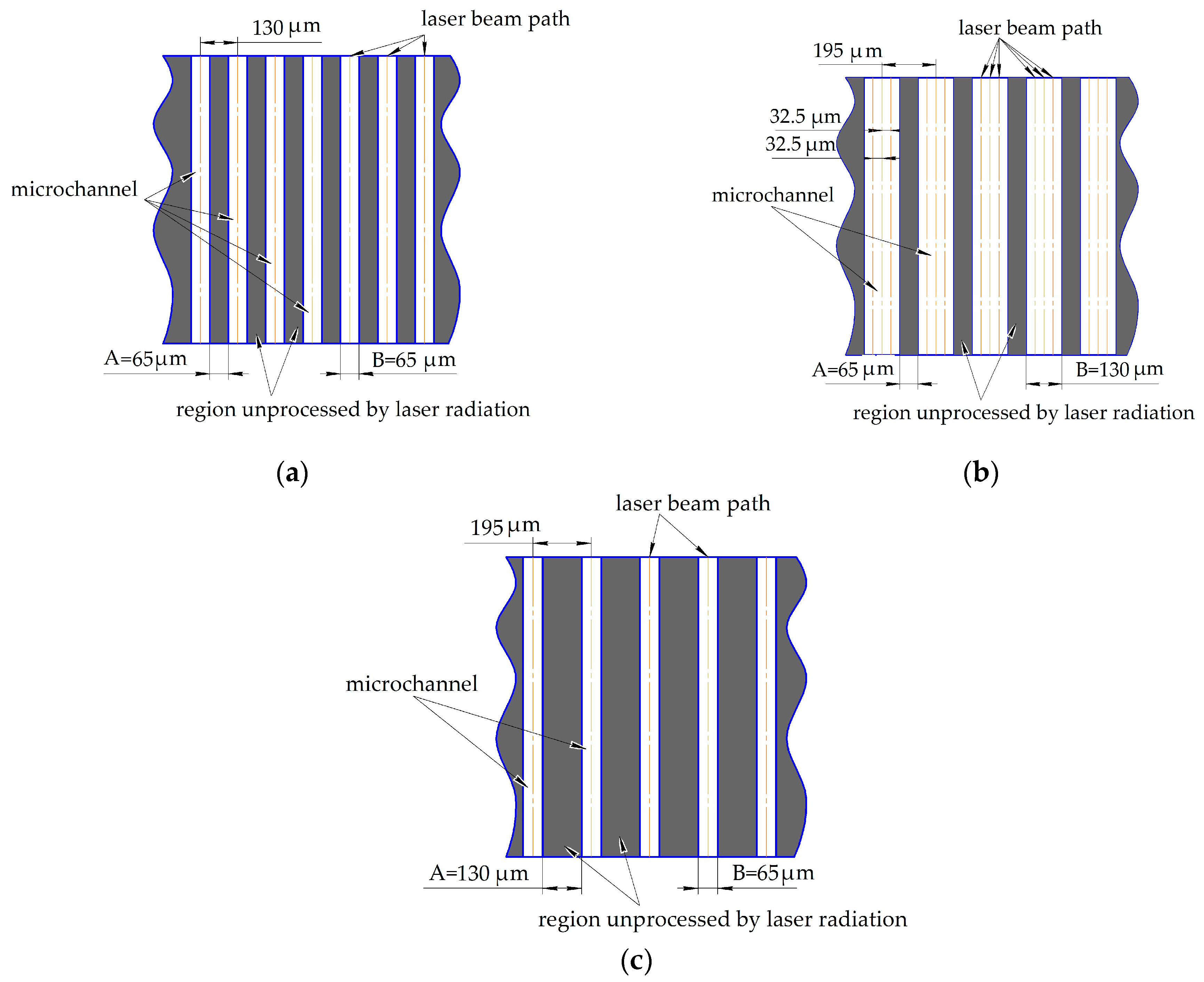
Figure 2 presents a schematic representation of a texture configuration in the form of parallel microchannels developed at the planning stage. The designation of textures (AB, A2B, and 2AB) means A is the width of the surface area that is not subject to laser radiation and B is the width of the surface area treated with laser radiation.
On the AB surface (Figure 2a), it was projected that the distance between the optical paths of the laser beam is 130 µm. At a generated pulse frequency of 110 kHz, a beam linear speed over the surface of 180 mm/s, and the formation of an ablation crater with a diameter of da.c. = 65.3 ± 0.4 µm, the overlap of ablation craters formed along the beam path is ka.c. ≈ 97.5% (ka.c. = (1 − x)·100%, where x is the relative distance between centers of ablation craters x = v/(φ·da.c.)). Under such conditions of laser processing, a microchannel with a width equal to the ablation crater diameter (about 65 µm) is formed on the X16CrNi25-20 steel surface along the beam motion trajectory.
On the A2B surfaces (Figure 2b), the width of the textured surface area (130 µm) is designed to be twice the width of the non-textured surface area (65 µm). To obtain a microchannel with a width of 130 μm, the beam is projected to pass along three parallel trajectories with a distance between the beam trajectories of about 32.5 μm.
The texture on the 2AB surface (Figure 1c) is designed with a distance between the beam trajectories equal to 195 µm. Under such laser treatment conditions, the width of the microchannel is 65 µm and the width of the untextured area is 130 µm.
After texture modification by mechanical (polishing) and non-contact methods (laser radiation), steel samples were cleaned successively in an ultrasonic bath in C3H8O medium and ultrapure water.

2.3. Methods and Equipment for Analysis of the Texture Configuration on Steel Surfaces

SEM images of mechanically and laser-modified textures were obtained using a Hitachi S-3400N microscope (Hitachi, Tokyo, Japan). The roughness of the studied steel surfaces was analyzed using the Micro Measure 3D station profilometer (STIL, Aix-en-Provence, France). Three regions (800 × 800 µm2 each) were randomly selected on the steel surface. They were scanned with a scanning step of 0.1 µm. Based on the results of the obtained data averaged over three measurements, the geometric characteristics of the microchannels were determined, as well as the three-dimensional roughness parameters in individual local regions of the surface. According to the recommendations [26], the surface roughness was analyzed based on the estimation of amplitude (Sa an Sz) and hybrid (Sdr) parameters. The measurement error of the geometric characteristics of microchannels and 3D roughness parameters did not exceed 10%.

2.4. Experimental Technique

2.4.1. Experimental Setup of a Mixed Heat Supply to a Fuel Droplet

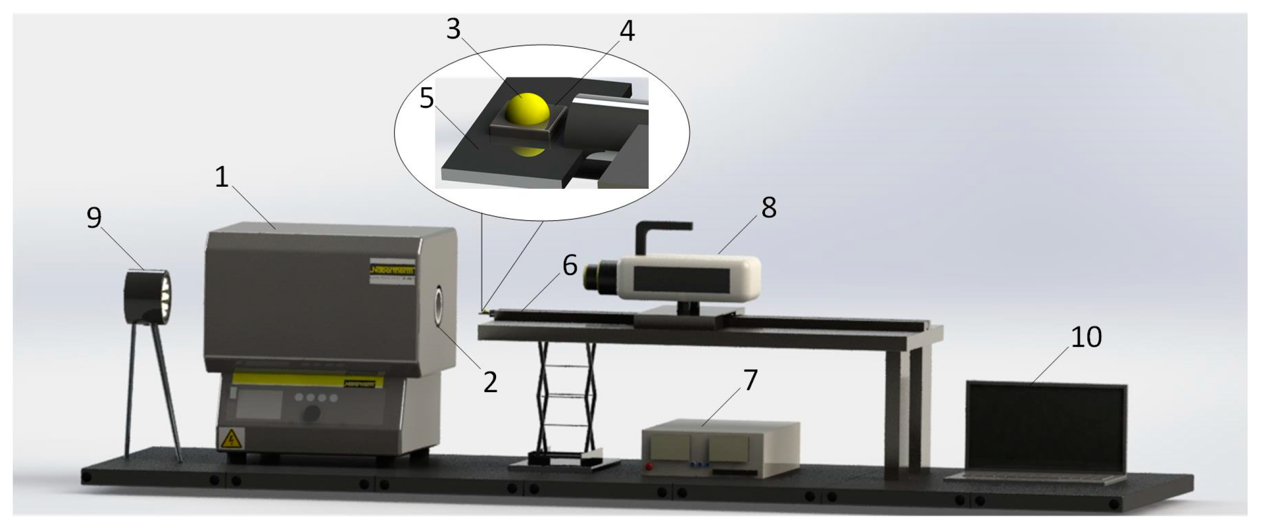
Figure 3 shows the model of the experimental setup that simulates the conditions of a mixed heat supply from the heating source of power-generating equipment to a fuel droplet. The mixed heat supply mechanism (convective, radiative, and conductive) was implemented using a tubular muffle furnace 1. The air temperature (Te) of 950 °C in the cavity of the ceramic tube of furnace 2 corresponded to the temperature in the furnace of modern power-generating equipment operating in the nominal mode.
A fuel droplet 3 (emulsion, slurry, or oil) with a volume of 10 µL was dosed onto the steel surface 4 and placed on a tripod 5 of a high-precision coordinate mechanism 6 with an automatic control unit 7. The fuel and surface temperatures corresponded to the ambient temperature in the laboratory (22–24 °C). After dosing the fuel droplet, the steel was introduced into the ceramic tube cavity, which was preliminarily heated. The ignition and combustion processes of a fuel droplet were recorded using a high-speed video camera 8 located on the coordinate mechanism. To ensure contrast, the steel in the ceramic tube was illuminated by a spotlight 9. The resulting video frames were processed in the commercial software Tema Automotive and Phantom Camera Control using a computer 9.

2.4.2. Experimental Setup of a Conductive Heat Supply to a Fuel Droplet

Figure 4 presents the model of the experimental setup of a conductive heat supply to a fuel droplet.
The modified steel surface 1 was placed in the working area of the electromagnetic inductor 2. The surface was heated by Foucault currents generated by an alternating electromagnetic field of a copper induction coil 3 with a diameter of 8 mm. The inductor electronic control unit 4 made it possible to set the characteristics of the generated electromagnetic field for heating the surface to a temperature of 950 °C. The steel surface temperature was controlled using a thermal imaging camera 5. The copper coil was cooled with water at a temperature of 10 °C. The temperature of the cooling water was controlled by chiller 6. A fuel droplet 7 (emulsion, slurry, and oil in the usual state) with a volume of 5 µL was placed at the end of a special holder 8. The holder was used to exclude uncontrolled movement of the droplet caused by the formation of a vapor cushion from the vapor products of the droplet. A fuel droplet located on a special holder was placed on a heated steel surface. Video recording of the processes under study was conducted with a high-speed video camera 9. The heating working area was illuminated with light using a spotlight 10. The experiments were performed under laboratory conditions.

2.5. Methods of Determining the Ignition and Combustion Characteristics of Fuel Droplets

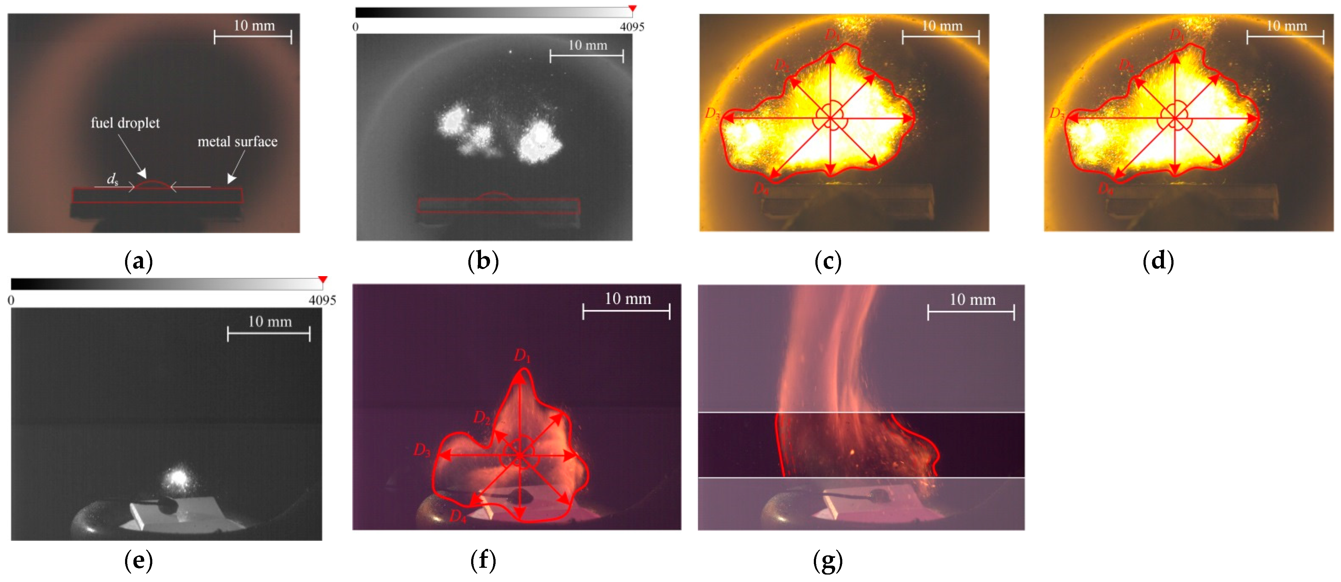
Each experiment was repeated at least five times under identical initial conditions for a mixed and conductive heat supply to a fuel droplet. The obtained video recordings of the ignition and combustion of fuel droplets were processed in accordance with previously developed algorithms [27] using Tema Automotive and Phantom Camera Control software. Figure 5 shows typical frames of video recording processing. In the experiments, the main characteristics of ignition and burnout of fuel droplets were determined, including the ignition delay time (τd) (Figure 5b,e), the maximum size of the fuel burnout region (Dmax) (Figure 5c,f), the number of puffing initiations (N) (Figure 5d,g), and the burnout time (τburn). In experimental studies with a mixed heat supply, the contact diameter of the spreading of fuel droplets (ds) was additionally determined (Figure 5a).
The contact diameter of spreading fuel droplets ds (Figure 5a) was registered 5–6 s after dosing a droplet on the surface under laboratory conditions. During such a period of time, a fuel droplet achieves a quasi-equilibrium state (balancing the forces acting on it). The systematic error in determining the contact diameter of fuel droplets due to the high-speed video camera resolution did not exceed 4%.
The ignition delay time (Figure 5b,e) was determined from frames of videograms in monochrome colors. The ignition delay time was taken as a time period between two events. The first event is placing the steel with a fuel droplet at a given point in the ceramic tube of the furnace for a mixed heat supply (Figure 5b) or placing a special holder with a droplet placed on it on the steel surface preliminary heated to a given temperature for a conductive heat supply (Figure 5e). The second event is when the image brightness values exceeded 220 units. The fuel burnout time was determined from monochrome images from the start of ignition to the achievement of image brightness values of less than 219 units in terms of color range. The random error in determining τd and τburn did not exceed 10%.
The maximum size of the fuel burnout region (Figure 5c,f) was determined from color videograms. The burnout region was automatically controlled (by image contrast) on the frames of high-speed video recording. By azimuth with a step of 45 degrees, the value of the width of the burnout region was determined. The maximum size of the fuel burnout region was determined as the arithmetic mean of the four measurements. The random error in determining Dmax did not exceed 10%.
The number of puffing initiations (Figure 5d,g) was determined from the statistical data on the separation of fragments of child droplets from the parent droplet by determining the change in the characteristic size of the burnout region. The number of puffing initiations was taken to be the value of positive peaks in the change in the characteristic size of the burnout region. The random error in determining N did not exceed 7%.

3. Results and Discussion

3.1. Analysis of Surface Microtexture and Roughness

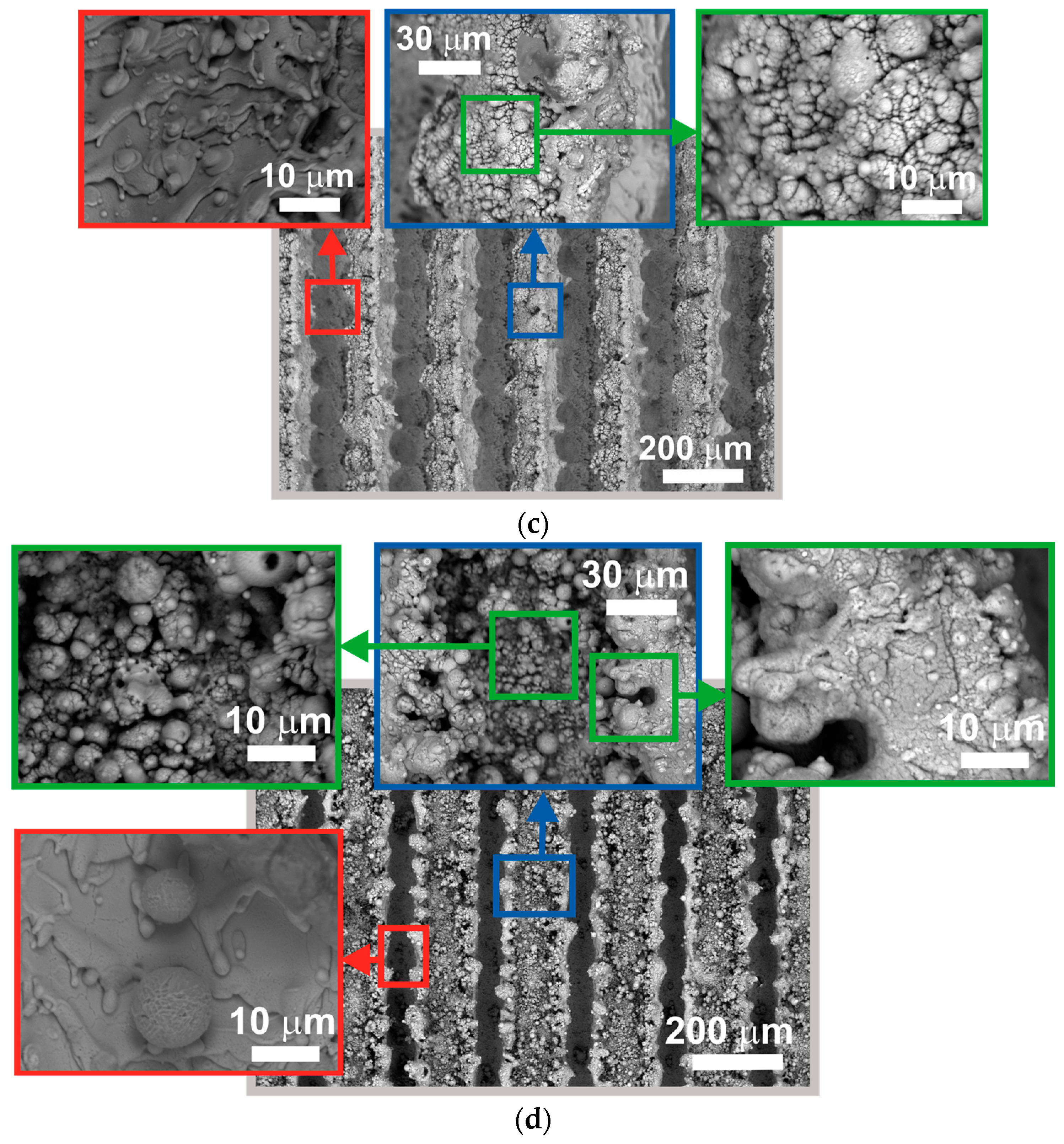
Figure 6 presents SEM images of polished and modified steel surfaces by laser radiation after conducting the experiments on the ignition and combustion of slurry droplets. SEM images of surfaces after ignition and combustion of oil and emulsion droplets are not presented because slurry leaves the highest ash deposition compared to other used fuels. It should be noted that SEM images of surfaces (Figure 6) were obtained after their cleaning with air at a pressure of 10 bar. This method of cleaning the heating surfaces of power-generating equipment is often used in practice.
Table 2 presents 3D roughness parameters obtained by optical profilometry. For AB, A2B, and 2AB, roughness parameters were determined for processed by laser radiation (the red frame in Figure 6) and unprocessed (the green and blue frames in Figure 6) local regions separately, as well as for a typical surface area, which combines processed and unprocessed regions (the gray frame in Figure 6).
Based on the analysis of textures formed by laser radiation (Figure 6), it was found that the bottom of the microchannels formed by laser radiation consists mainly of crystallized metal layers, drops, and jets. There are also rarely located spherical particles 7–10 µm in size at the microchannel bottom (Figure 6d, the red frame). The hypothesis about the formation mechanism of these particles was formulated. Texturing metal surfaces by laser radiation with an energy above the ablation threshold of the material results in temperature increases of about 3000 K in the region of laser beam action. Under such conditions, all oxygen in the area affected by the laser beam burns out. When the action of the laser pulse is terminated, the oxygen contained in the environment penetrates the melt material. If the melt is formed in the form of drops, then as the melting drop is saturated with oxygen, its size increases due to heating and the exothermic thermal effect. Simultaneously with these processes, crystallization is realized with the formation of spherical elements.
It was also found that evaporated material due to laser action on the regions subjected to processing condensed on the regions unprocessed by laser radiation. The texture in these regions looks like a cauliflower (Figure 6, the blue and green frames). Therefore, it is concluded that laser methods for forming the textures in the form of microchannels up to 130 µm wide and with a distance between beam paths of no more than 195 µm on steel surfaces lead to the modification of the entire surface, including unprocessed regions (that have not been exposed to direct laser exposure) due to metal vapor deposition on them.
It is known that the ignition and combustion characteristics of fuel droplets interacting with the heating surface depend on the fuel fragment (droplet)/heating surface interfacial area [16,28]. The higher the surface roughness, the greater this area is. To estimate the increase in surface area due to texture, the 3D roughness parameter Sdr is used. With an increase in the fuel/heating surface interfacial area, the heat exchange between the fuel droplet and the surface is intensified. This significantly affects the improvements in fuel ignition and combustion [16,28]. As can be seen in Table 2, polishing using abrasives slightly increases the surface area (Sdr does not exceed 1%). Laser texturing allows increasing the surface area by 104% for AB texture configuration, by 89% for A2B, and by 127% for 2AB. The bottom microchannels formed by the crystallized metal has an insignificant roughness compared to the texture formed by ablation products on unprocessed regions. The Sa and Sz parameters determined in the regions of the microchannel bottom are more than 1.3–1.4 (Sa) and 1.5–2.5 (Sz) times less than that of the unprocessed regions (between microchannels). Therefore, a significant contribution to the increase in surface area on the AB, A2B, and 2AB surfaces is made by the texture formed by the ablation products on the local unprocessed regions. The Sdr parameter in these regions range from 31 to 44%.
It was found in [16,28] that the texture formation on metal surfaces by laser radiation makes it possible to significantly reduce the adhesion of combustion products deposited on them, despite high roughness. SEM images of surfaces previously cleaned from contaminants with air at a pressure of 10 bar show that there are no deposits after the combustion of oil, emulsion, and slurry droplets. Therefore, it is reasonable to assume that the texture configuration in the form of microchannels formed by laser radiation makes it possible to significantly increase the resistance of heating surfaces to the adhesion of fuel combustion products.
Each microchannel was formed on the AB and 2AB surfaces due to passing the beam along one trajectory with identical energy characteristics and with ten repetitions. Consequently, the microchannels were formed on these surfaces under identical heat supply conditions. Therefore, the heights of microchannels (hm.c.) formed on the AB (Figure 6b) and 2AB (Figure 6d) are almost identical hm.c = 171–172 µm. This was evaluated using the values of Sz (Table 2). The microchannels on the A2B surface were formed when the beam passed along three parallel trajectories and with ten repetitions. In this case, the heat input to the material was greater than in the case of the AB and 2AB surfaces. It means that the microchannels were formed at a more intense ablation of the material compared to the AB and 2AB surfaces. For these reasons, their height (hm.c = 245 µm) exceeds the height of microchannels on the AB and 2AB surfaces by more than 1.4 times.
As can be seen in Figure 6, the dimensions of the texture, including the width of processed (the microchannel width) and unprocessed local regions correspond quite well to the dimensions of specified textures at the planning stage using the ablation crater diameter in calculations (Section 2.2). The deviations from the specified texture parameters (the width of microchannels and the width of unprocessed regions) do not exceed 6 μm (Figure 6), which is no more than 10%. The deviations are associated with edge formation by ablation products along the edges of microchannels. It can be concluded that the proposed method for predicting the geometric dimensions of textures in the form of parallel microchannels formed by nanosecond laser pulses based on the use of the ablation crater diameter in calculations has a fairly good accuracy (the deviations did not exceed 10%).

3.2. Analysis of Fuel Ignition and Combustion

Previously, it was found that laser modification of surfaces makes it possible to intensify the processes occurring on them [15,29,30,31,32]. Among such processes are not only the flow of liquids [29], evaporation [30], boiling [31], and condensation [32], but also fuel ignition and combustion [15]. However, it has not yet been established how the configuration of the texture formed by laser radiation affects these processes, and also which configuration provides the most intense ignition and combustion of liquid fuels under conductive or a mixed heat supply.

3.2.1. Analysis of the Fuel Droplet Ignition and Combustion Characteristics under a Mixed Heat Supply

When studying ignition and combustion of liquid fuels under a mixed heat supply, the temperature of the fuel droplet and the steel surface, on which the droplet was placed, corresponded to laboratory conditions. Under such conditions, the ignition and combustion characteristics are significantly affected by the fuel droplet/heating surface and fuel droplet/high-temperature environment interfacial areas. They are determined by the parameter of the interfacial interaction of a liquid with a solid body, which is the contact diameter (ds) of spreading fuel droplets over the surface.
Table 3 presents the contact diameters of fuel droplets (oil in the usual state, emulsion, and slurry) as they spread over surfaces P, AB, A2B, and 2AB. The contact diameters on the AB, A2B, and 2AB surfaces were measured in two directions due to microchannel configuration: parallel and perpendicular to the microchannels (longitudinal and transverse spreading of the droplet with respect to the microchannels).
It was found that among three fuels used in experiments (oil in the usual state, emulsion, and slurry) with an identical droplet volume, the oil spreads over the steel surfaces with the largest contact diameter and the slurry with the smallest one (Table 3). This is due to the aggregation state of the dispersion medium and the dispersed phase of fuels.
As can be seen in Table 3, the contact diameter of fuels in the longitudinal direction of spreading is 1.5–2.5 times larger than that for transverse spreading on the AB, A2B, and 2AB surfaces. This is connected with the fact that, during transverse spreading, the microchannels act as energy barriers and prevent the movement of the contact line over the surface. Therefore, the droplet has an elongated shape along the microchannels. For the same reason, the spreading diameter in the longitudinal direction is larger on the AB, A2B, and 2AB surfaces than on the polished surface P. However, in the transverse direction, the spreading diameter of the fuels on AB, A2B, and 2AB is smaller than on the polished surface P, despite the fact that laser-modified steel surfaces demonstrate superhydrophilic and superoliophilic properties. The contact angles formed between water droplets, as well as oil droplets and steel surfaces after laser texturing, did not exceed 5–7°-. Changes in the surface energy and wetting properties (up to the extreme, in particular, superhydrophilic and superoliophilic) are associated with the destruction of existing bonds by laser radiation and the formation of oxides on the surface, which are highly polar [33].
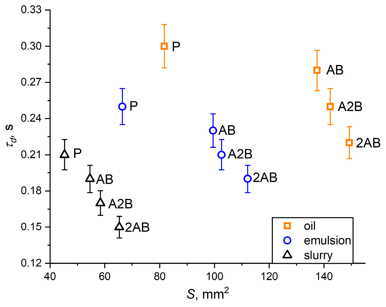
As noted above, the fuel droplets used in the experiment have an elongated shape when spreading over steel surfaces with a texture in the form of parallel microchannels (AB, A2B, and 2AB). Therefore, in the case of the AB, A2B, 2AB surfaces, it is incorrect to consider the dependences τd = f(ds). The experimentally obtained contact diameters of the spreading fuel droplets were used to calculate the projection areas of the fuel droplet/heating surface interface (S). The fuel droplets on the P surface have a spherical segment form and their base area is close to a circle. Therefore, S = π·ds2/4, where ds is the contact diameter of the fuel droplet. On the AB, A2B, and 2AB surfaces, the droplet base is close to an ellipse. Therefore, the projection area was determined by the formula S = π·(d)/2·(d)/2, where (d) and (d) are the contact diameters of droplet fuel measured in parallel and perpendicular directions with respect to the microchannels. It can be seen from dependences τd = f(S) (Figure 7) that the larger the projection area of the fuel droplet/heating surface interface, the shorter the ignition delay time of fuel droplets (oil in the usual liquid state, emulsion, and slurry) is. The larger S provides the larger contact areas of the droplet with the heating surface. Consequently, the intensity of heat transfer from the heating surface to the droplet is higher. Therefore, the droplet warms up faster and the evaporation intensity of the combustible components that make up the fuel is higher. The required concentration of combustible substances near the surface of the fuel droplet is achieved in less time to implement gas-phase ignition.
It was found that the ignition delay times of fuel droplets located on surfaces textured by laser radiation are shorter than on a polished surface for all types of fuels used in experiments (oil, emulsion, and slurry) for all other conditions being equal (Figure 7). For example, the difference in the ignition delay times of fuel droplets located on surfaces 2AB (the smallest values of τd were recorded) and P (the largest values of τd were recorded) in the case of oil is 25%, emulsion is 28%, and slurry is 55%. It is to be noted that among the formed textures AB, A2B, and 2AB, the best result in intensifying the ignition was achieved on surfaces with the 2AB texture configuration. For example, the difference in the values of τd recorded on the 2AB and AB surfaces is 18% for the ignition of oil droplets, 17% for emulsions, and 36% for slurry. As noted above, the decrease in ignition delay times is due to the larger contact area between the fuel droplet and the heating surface.
As is seen in Figure 7, the contact area between the fuel droplet and the heating surface increases in the sequence P-AB-2BA-2AB, other conditions being equal. This is due to the fact that in the same sequence (P-AB-2BA-2AB), fuel droplets spread better over surfaces. It is obvious that the best spreading on the AB, A2B, and 2AB surfaces was facilitated by the fact that these surfaces demonstrated superhydrophilic and superoliophilic properties after laser processing. The wettability inversion of metal surfaces (the transition from hydrophilic/hydrophobic to superhydrophilic) after their processing with laser radiation has been studied quite well [34]. It should be noted that the 2AB texture configuration contributed to a greater spreading compared to the AB and A2B texture configurations. This is connected to the fact that on the 2AB surface, most of the texture consists of micro- and nano-sized elements formed due to ablation and further crystallization of the material.
It is noteworthy that the fuel droplet/heating surface interface, through which heat is transferred from the heating surface to the droplet, depends not only on the spreading area of the fuel droplet but also on the surface roughness. Obviously, with increasing roughness, the heat transfer surface area increases. As noted in Section 3.1, the increase in surface area due to roughness can be estimated using the 3D roughness parameter Sdr. The Sdr values (Table 2) show that the increase in surface area due to roughness increases in the sequence of the P-AB-2BA-2AB surfaces. In other words, it is in the same sequence in which the fuel droplets spread better. It is possible to conclude that among the texture configurations used in the experiments in the form of parallel microchannels, the 2AB texture configuration has the greatest positive effect on reducing the ignition delay time (Figure 7), not only due to better spreading of fuel droplets over it but also due to the greatest increase in surface area as a result of developed roughness.
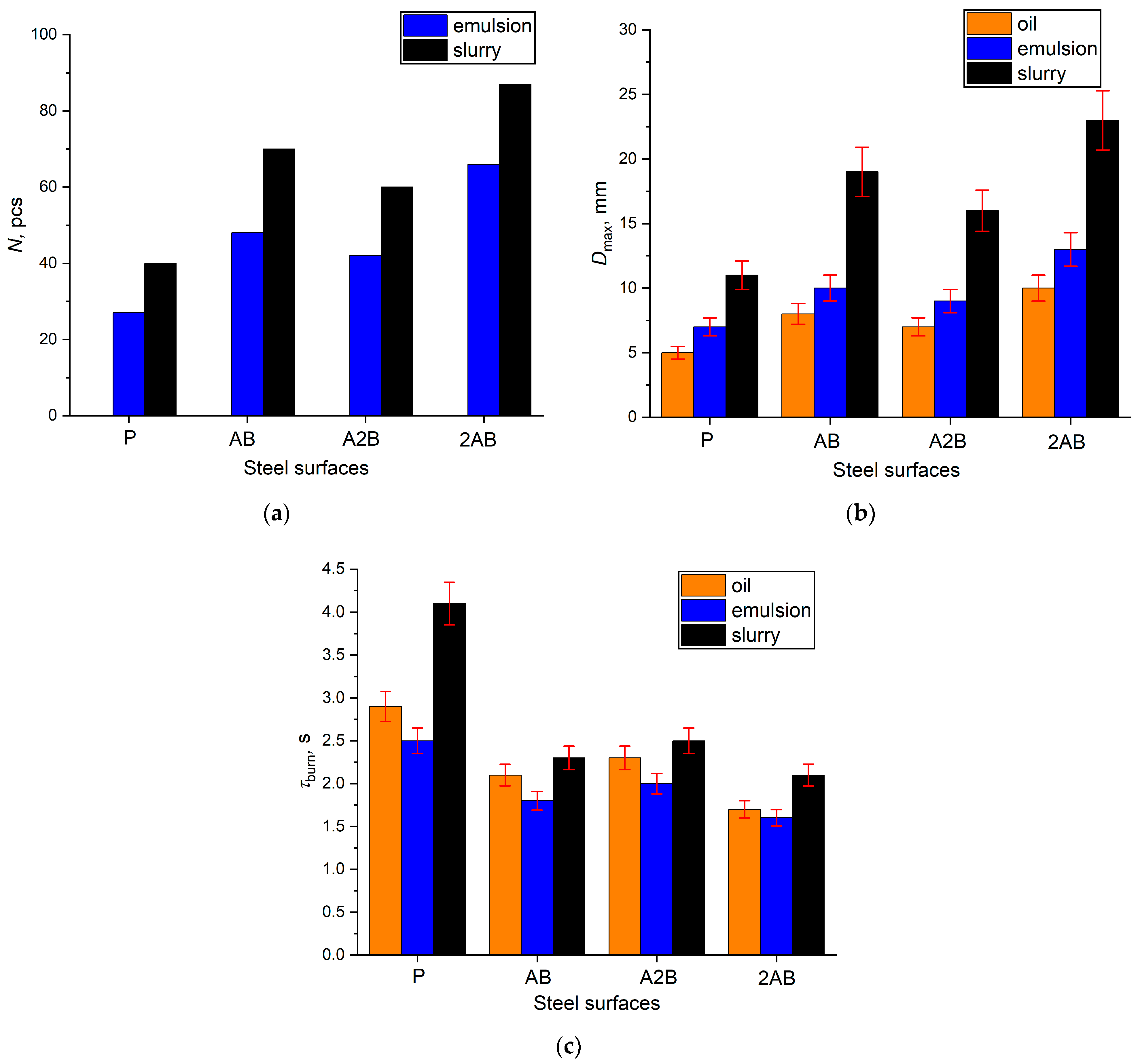
It is known that fuel droplets can ignite and burn out in one of the following conventionally distinguished regimes: evaporation, boiling, puffing, and microexplosion [35,36]. For oil in the usual state, there is no secondary atomization when heat is supplied to the droplet; it evaporates and boils. The puffing and microexplosion regimes are typical only for multicomponent fuels. Figure 8a shows the number of puffing initiations of emulsion and slurry droplets under a mixed heat supply. The intensity of puffing, as well as the size of the burnout region, where a combustible vapor–gas mixture is formed during physical and chemical processes, largely affects the intensity of combustion of multicomponent fuels. The greater the number of puffing initiations (Figure 8a) and the larger the burnout region (Figure 8b), the faster the droplets of multi-component fuels will burn out (Figure 8c). In order of increasing the burnout time of liquid fuel droplets, the steel surfaces are arranged in the following sequence: 2AB-AB-A2B-P. Figure 8 shows that the smallest values of the number of puffing initiations and the maximum size of the burnout region were recorded during the ignition and combustion of liquid fuel droplets on the polished surface. Under such conditions, the burnout time will be longer than on textured heating surfaces. The highest values of N and Dmax and the lowest values of τburn were recorded on the 2AB surface for the fuels used in the experiments, other conditions being equal. For example, for a slurry droplet, the burnout time on the 2AB texture is two times less than that on the polished steel surface. Thus, it can be concluded that physicochemical processes occurring under the conditions of fuel ignition and combustion are realized much more intensively on the 2AB texture compared to the use of polished, AB, and A2B textures as heating surfaces.
It should be noted that the values of the combustion characteristics (N, Dmax, and τburn) presented in Figure 8 for a mixed heat supply to the AB and A2B surfaces differ slightly from each other and lie in the range of the confidence interval. It is also necessary to clarify that the comparison of the ignition and combustion characteristics of the three types of fuels is incorrect due to the different compositions and, consequently, different physical and chemical properties. In addition, the same volumes of droplets of oil in the usual state, emulsion and slurry, were used in the experiments. However, due to the different component compositions, their masses differed from each other. Therefore, on the same surface, for example, 2AB, the times of complete burnout of an emulsion droplet are shorter than the τburn of a slurry droplet, despite its more intense puffing.

3.2.2. Analysis of the Fuel Droplet Ignition and Combustion Characteristics under a Conductive Heat Supply

In the conducted experiments on the ignition and combustion of fuel droplets under a conductive heat supply from the heating surface, the nominal operating conditions of boiler units were reproduced. In the combustion chambers of boiler units, fuel droplets collide with internal surfaces heated to high temperatures. Based on the experimental results, we conducted an analysis of the influence of the texture configuration formed on steel surfaces by laser radiation on the ignition (τd) (Figure 9) and combustion (N, Dmax, and τburn) (Figure 10) characteristics of fuel droplets (oil, emulsion, and slurry).
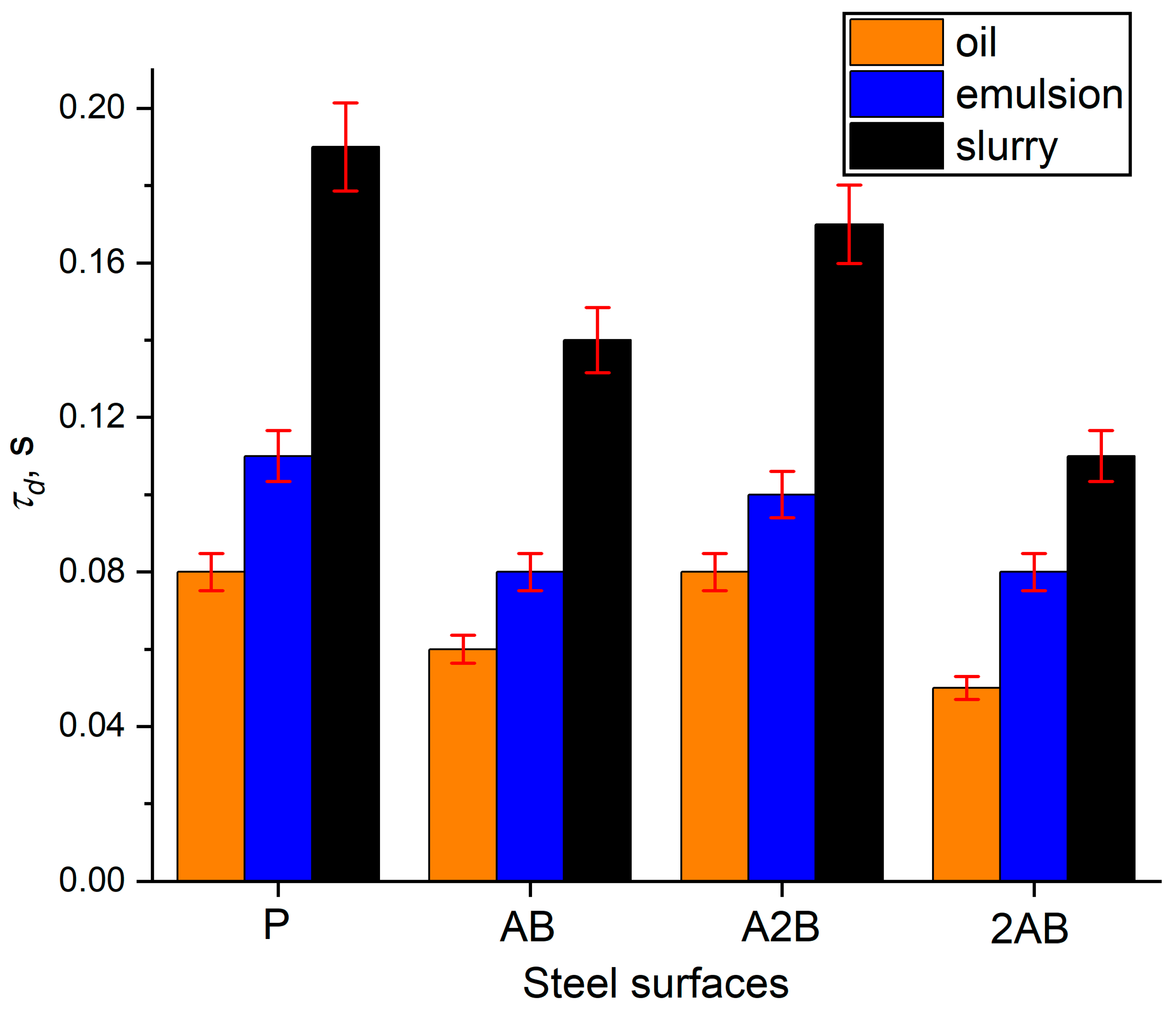
It can be seen in Figure 9 that in the case of a mixed heat supply, laser processing of steel surfaces helps to reduce the ignition delay time under a conductive heat supply. For example, τd of a suspension droplet on the 2AB surface is 40% less than that on the polished surface P (Figure 9). It was found that the texture configuration has a significant effect on the ignition and combustion characteristics (Figure 9). Among the texture configurations used in the experiments, the shortest ignition delay times for oil droplets, emulsions, and slurries were recorded on the 2AB surface, all other conditions being equal. On the 2AB surface, the area of the regions unprocessed by laser radiation is twice the area of the regions processed by laser radiation. Since the deposition of metal vapors and crystallization of melt material occurs on unprocessed regions (Figure 6d), these regions are characterized by significant roughness and a developed hierarchical multimodal texture. This is the cause of a significant increase in the surface area of regions unprocessed by laser radiation due to roughness (formed texture). Under the conditions of the experiment, a vapor layer (the evaporated products that make up the fuel) was formed between a fuel droplet and the steel surface. Despite the fact that heat from the heating surface to the fuel droplet is transferred through a vapor layer, the intensity of heat transfer from the 2AB surface to the droplet was higher than on the P, AB, and A2B surfaces. This is due to the fact that the 2AB surface has the largest surface area among the surfaces used in the experiment. The higher the intensity of heat transfer from the surface to the fuel droplet, the higher the evaporation intensity of the combustible components that make up the fuel. As a result, the necessary concentration of combustible substances is formed near the droplet for a shorter period of time for the implementation of gas-phase ignition. For these reasons, the ignition delay times of fuels on the AB surfaces are smaller. The effect of the increase in surface area on the ignition characteristics is especially noticeable when comparing the results obtained using the AB and A2B surfaces. In contrast to the conditions of a mixed heat supply (Figure 7), fuel droplets on the AB texture configuration under a conductive heat supply ignited faster than on the A2B texture configuration, all other conditions being equal. The reason for this can only be a larger increase in the surface area due to the roughness on the A2B surface (Table 2) since the contact diameter of the droplets in all experiments with a conductive heat supply was constant (limited by the size of a special holder).
Based on the results obtained, it can be concluded that when power-generating equipment operates in the nominal mode, in order to reduce the ignition time of oil droplets in a liquid state, emulsion, and slurry, it is necessary to create a developed multimodal roughness on the heating surfaces characterized by the largest growth of the surface area. The laser technology for processing heating surfaces made of X16CrNi25-20 steel makes it possible to create a texture in the form of microchannels with specified geometric dimensions and to control the roughness over a fairly wide range of 3D parameters. In this case, it is possible to increase the area of heating surfaces by more than two times due to the creation of microchannels and the developed multimodal roughness consisting of elements of crystallized melt. An increase in the surface area due to roughness makes it possible to reduce the ignition delay time of droplets of composite fuels (slurries and emulsions), as well as liquid fuels by up to 40% under the conditions of operation of power-generating equipment in the nominal mode.
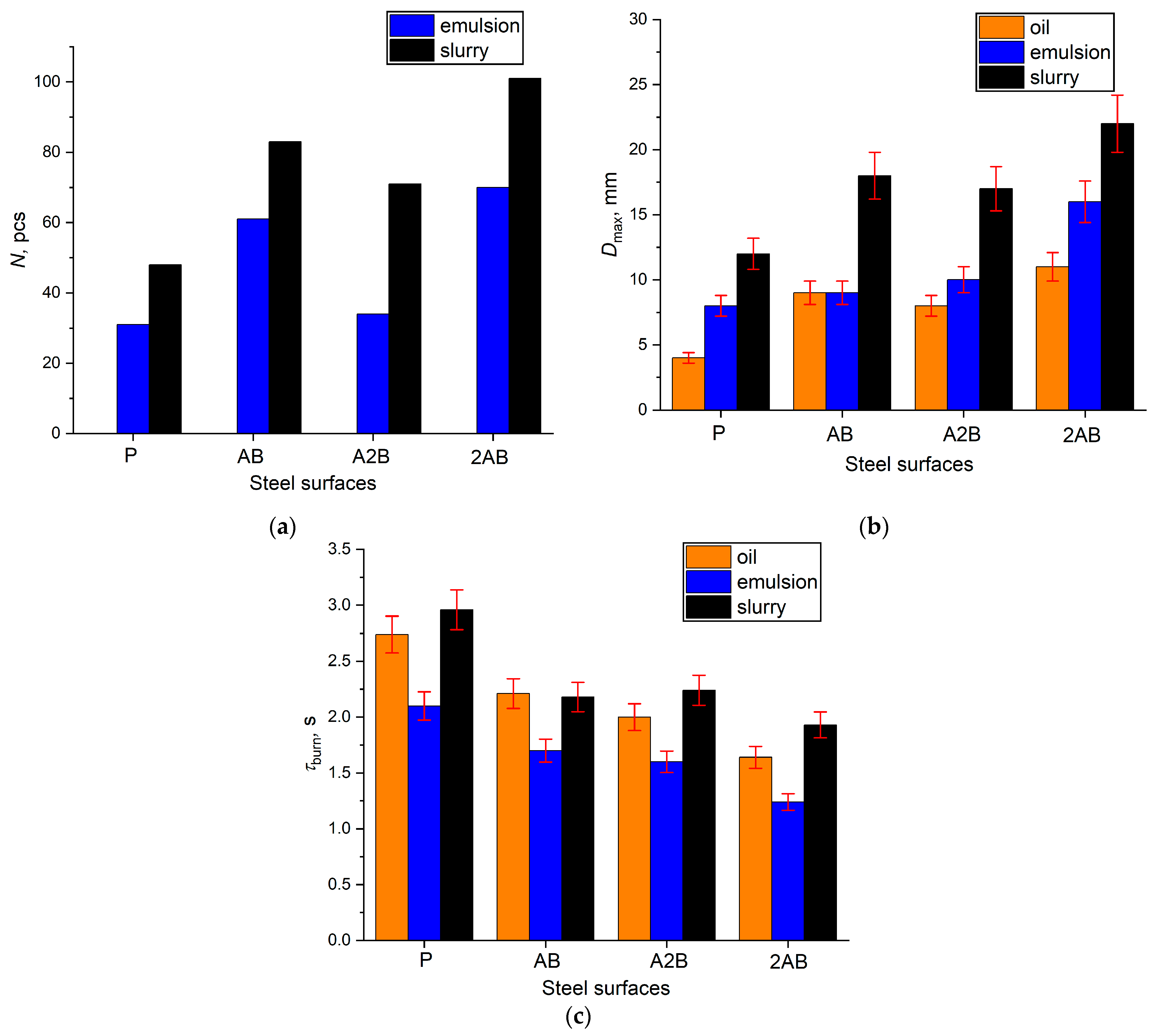
Figure 10 shows the combustion characteristics of liquid fuels on steel surfaces, including the number of puffing initiations (Figure 10a), the maximum size of the burnout region (Figure 10b), and the burnout time of fuel droplets (Figure 10c).
It can be seen in Figure 10c that among the texture configurations used in the experiments, the shortest burnout time for droplets of oil, emulsion, and slurry fuels was recorded on the 2AB surfaces, all other conditions being equal. The result obtained, as well as the above-established conclusions, is explained by a more developed surface due to the selected texture configuration. Thus, the decrease in burnout times on the 2AB surface compared to the polished surface, in the case of combustion of oil droplets, is more than 40%, in the case of emulsion it is 40%, and in the case of slurry it is 34%.
In addition, the texture configuration also affects other basic combustion characteristics, such as the maximum size of the burnout region (Figure 10a). In the case of burning emulsion and slurry droplets, which include water in addition to combustible components, the texture also affects the number of puffing initiations (Figure 10b). It is fairly well known [37,38,39] that puffing is caused by the multicomponent fuel composition, which necessarily includes two mutually insoluble liquid components. Among the considered texture configurations, the 2AB surface is characterized by the most developed roughness (Table 2). The higher the surface roughness, the more stable nucleation centers on it. For this reason, the number of puffing initiations during the combustion of emulsion and slurry droplets on the 2AB surface is greater than on the AB and A2B surfaces. For oil droplets in the usual state, there is no secondary atomization during combustion; for this reason, it is not presented in Figure 10a.
An increase in the number of puffing initiations intensifies the combustion process by increasing the burnout region. This is illustrated by the established dependencies in Figure 10b. In addition, the dependencies in Figure 10b demonstrate the effect of the developed texture on the increase in the maximum size of the burnout region of fuel droplets (oil in the usual liquid state) burning without secondary atomization. It was found that it is possible to increase the size of the fuel droplet burnout region by 65% (the largest increase in Dmax was recorded in the case of oil droplet combustion on the 2AB surface compared to combustion on the P surface) due to the developed texture. Based on the results obtained, it can be concluded that in order to intensify the combustion of both liquid and composite (emulsions and slurries) fuels under conditions corresponding to the nominal operating mode of power-generating equipment, it is preferable to use heating surfaces with a more developed texture in practice. Among the texture configurations used, which are formed by laser radiation, the 2AB texture demonstrates the best results in assessing the characteristics of ignition (τd) and combustion (τburn, N, and Dmax) of fuel droplets, including composite fuels. This texture consists of parallel microchannels with a width of about 65 μm with a distance between the axes of the microchannels equal to 195 μm. It has a developed texture on the regions unprocessed by laser radiation, but is formed by crystallized melt.

4. Conclusions

  • A graphic-analytical method was developed to predict the formation of textures in the form of microchannels with specified dimensions and controlled roughness using laser technology for processing metal surfaces. Using the diameter of the ablation crater in the calculations allows for the prediction of the texture in the form of microchannels with an accuracy of 10%.
  • It was experimentally proven that the texture configuration in the form of microchannels on the surfaces of X16CrNi25-20 steel formed by nanosecond laser radiation makes it possible to significantly increase the resistance of surfaces to the adhesion of products left after the combustion of liquid and composite fuels.
  • The texture configuration in the form of microchannels on metal surfaces leads to decreasing the ignition, up to 25% for oil, up to 28% for emulsion, and up to 55% for slurry under conditions corresponding to the start-up of power-generating equipment. This is connected with the best spreading of fuel droplets over the heating surfaces modified by laser radiation and the largest increase in the surface area due to the developed roughness.
  • In practice, the heating surfaces textured in the form of microchannels contribute to the fuel combustion intensification under start-up conditions of power-generating equipment. In particular, the maximum size of the burnout region increases by more than 50%, and for composite fuels, the number of puffing initiations increases, which ultimately reduces the burnout time of the fuel droplets.
  • Under the nominal operating mode conditions of power-generating equipment, the heating surfaces textured in the form of microchannels makes it possible to reduce the ignition delay time of composite fuels, as well as liquid fuels widely used in practice, by up to 40%.
  • In the experiments reproducing the nominal operating mode, as well as the start-up of power-generating equipment, the best results according to the ignition (τd) and combustion (τburn, N, and Dmax) characteristics of fuel droplets were demonstrated by the 2AB texture. This is characterized by parallel microchannels that had a width of about 65 µm with a distance between the axes of the microchannels equal to 195 µm and a developed texture on the unprocessed region of the surface by laser radiation, but this was formed by crystallized metal melt.

Author Contributions

Conceptualization, D.G. and D.F.; methodology, E.O.; validation A.A.; investigation, S.B.; data curation, D.F.; writing—original draft preparation, E.O.; writing—review and editing, D.G.; visualization, A.A.; supervision, D.G.; funding acquisition, D.G. All authors have read and agreed to the published version of the manuscript.

Funding

The study was supported by the program of the National Research Tomsk Polytechnic University (Priority-2030).

Conflicts of Interest

The authors declare no conflict of interest.

Abbreviations

CWFcoal-water fuel
OCWForganic coal-water fuel
Nomenclature
Awidth of the local region on the surface, which is unprocessed by laser radiation, µm
Adash, %
Bwidth of the local region on the surface, which is processed by laser radiation, µm
Dmaxmaximum size of the burnout region of fuel, mm
Nnumber of puffing initiations, pcs
Qas,Vhigher heating value, MJ/kg
Sthe projection area of the fuel droplet/heating surface interface, mm2
Saarithmetic mean surface deviation, µm
Sdrdeveloped interfacial area ratio, %
Szmaximum height of irregularities, µm
Tethe temperature of the gas medium in the muffle furnace, °C
Vdafvolatile content, %
Wamoisture content, %
da.c.diameter of ablation crater, µm
dscontact diameter of droplet spreading, mm
dcontact diameter of droplet spreading parallel to microchannels, mm
hm.cheight of microchannels, µm
dcontact diameter of droplet spreading perpendicular to microchannels, mm
ka.c.coefficient of ablation crater overlapping, %
vlaser beam speed, mm/s
xthe relative distance between centers of ablation craters
Greek Symbol
φpulse frequency, kHz
τburnburnout time, s
τdignition delay time, s

References

  1. Investment in Renewable Energy, by Technology. Available online: https://ourworldindata.org/grapher/investment-in-renewable-energy-by-technology (accessed on 25 October 2022).
  2. Pinchuk, V.A.; Sharabura, T.A.; Moumane, M.; Kuzmin, A.V. Experimental Investigation of the Influence of Temperature, Coal Metamorphic Stage, and of the Size of Coal-Water Fuel Drop on the Fuel Drop Combustion Process. Int. J. Energy Clean Environ. 2019, 20, 43–62. [Google Scholar] [CrossRef] [Green Version]
  3. Glushkov, D.O.; Kuznetsov, G.V.; Strizhak, P.A. Simultaneous Ignition of Several Droplets of Coal–Water Slurry Containing Petrochemicals in Oxidizer Flow. Fuel Process. Technol. 2016, 152, 22–33. [Google Scholar] [CrossRef]
  4. Staroń, A.; Banach, M.; Kowalski, Z.; Staroń, P. Impact of Waste Soot on Properties of Coal-Water Suspensions. J. Clean. Prod. 2016, 135, 457–467. [Google Scholar] [CrossRef]
  5. Boylu, F.; Dinçer, H.; Ateşok, G. Effect of Coal Particle Size Distribution, Volume Fraction and Rank on the Rheology of Coal–Water Slurries. Fuel Process. Technol. 2004, 85, 241–250. [Google Scholar] [CrossRef]
  6. Fei, Y.; Gopan, A.; Axelbaum, R.L. Characterization of Coal Water Slurry Prepared for PRB Coal. J. Fuel Chem. Technol. 2014, 42, 1167–1171. [Google Scholar] [CrossRef]
  7. Kijo-Kleczkowska, A. Combustion of Coal–Water Suspensions. Fuel 2011, 90, 865–877. [Google Scholar] [CrossRef]
  8. Burdukov, A.P.; Popov, V.I.; Tomilov, V.G.; Fedosenko, V.D. The Rheodynamics and Combustion of Coal-Water Mixtures. Fuel 2002, 81, 927–933. [Google Scholar] [CrossRef]
  9. Dorokhov, V.V.; Kuznetsov, G.V.; Vershinina, K.Y.; Strizhak, P.A. Relative Energy Efficiency Indicators Calculated for High-Moisture Waste-Based Fuel Blends Using Multiple-Criteria Decision-Making. Energy 2021, 234, 121257. [Google Scholar] [CrossRef]
  10. Osada, H.; Watanabe, H.; Onozawa, Y.; Enya, K.; Uchida, N. Experimental Analysis of Heat-Loss with Different Piston Wall Surface Conditions in a Heavy-Duty Diesel Engine. In Proceedings of the COMODIA 2017—9th International Conference on Modeling and Diagnostics for Advanved Engine Systems, Okayama, Japan, 25–28 July 2017; The Japan Society of Mechanical Engineers: Tokyo, Japan, 2017; p. B204. [Google Scholar]
  11. Tsutsumi, Y.; Nomura, K.; Nakamura, N. Effect of Mirror-Finished Combustion Chamber on Heat Loss. SAE Tech. Pap. 1990. [Google Scholar] [CrossRef]
  12. Kawaguchi, A.; Wakisaka, Y.; Nishikawa, N.; Kosaka, H.; Yamashita, H.; Yamashita, C.; Iguma, H.; Fukui, K.; Takada, N.; Tomoda, T. Thermo-Swing Insulation to Reduce Heat Loss from the Combustion Chamber Wall of a Diesel Engine. Int. J. Engine Res. 2019, 20, 805–816. [Google Scholar] [CrossRef]
  13. Moskvin, L.N.; Efimov, A.A.; Gusev, B.A. Protective Oxidation of Boiler Equipment Heating Surfaces with Concurrently Removing Ash Deposits. Therm. Eng. 2020, 67, 173–177. [Google Scholar] [CrossRef]
  14. Shchelkin, K.I. Selected Works [Collection of Scientific Articles]; Loboiko, B.G., Ed.; RFNC-VNIITF: Snezhinsk, Russia, 2011. [Google Scholar]
  15. Feoktistov, D.V.; Glushkov, D.O.; Kuznetsov, G.V.; Orlova, E.G.; Paushkina, K.K. Ignition and Combustion Enhancement of Composite Fuel in Conditions of Droplets Dispersion during Conductive Heating on Steel Surfaces with Different Roughness Parameters. Fuel 2022, 314, 122745. [Google Scholar] [CrossRef]
  16. Feoktistov, D.V.; Glushkov, D.O.; Kuznetsov, G.V.; Nikitin, D.S.; Orlova, E.G.; Paushkina, K.K. Ignition and Combustion Characteristics of Coal-Water-Oil Slurry Placed on Modified Metal Surface at Mixed Heat Transfer. Fuel Process. Technol. 2022, 233, 107291. [Google Scholar] [CrossRef]
  17. Misyura, S.Y.; Feoktistov, D.V.; Morozov, V.S.; Orlova, E.G.; Kuznetsov, G.V.; Islamova, A.G. Effect of Heat Treatment on Corrosion of Laser-Textured Aluminum Alloy Surfaces. J. Mater. Sci. 2021, 56, 12845–12863. [Google Scholar] [CrossRef]
  18. Long, J.; Zhong, M.; Zhang, H.; Fan, P. Superhydrophilicity to Superhydrophobicity Transition of Picosecond Laser Microstructured Aluminum in Ambient Air. J. Colloid Interface Sci. 2015, 441, 1–9. [Google Scholar] [CrossRef]
  19. Neuymin, V.M. The Results of Economic and Exergetic Analysis of Thermal Power Plants with Natural Gas Power Units. Energetik 2013, 7, 2–5. [Google Scholar]
  20. Belošević, S.; Tomanović, I.; Beljanski, V.; Tucaković, D.; Živanović, T. Numerical Prediction of Processes for Clean and Efficient Combustion of Pulverized Coal in Power Plants. Appl. Therm. Eng. 2015, 74, 102–110. [Google Scholar] [CrossRef]
  21. Alekhnovich, A.N.; Bogomolov, V.V.; Artem’yeva, N.V. Features of New Energy Coals Burning at Thermal Power Stations in Russia. Energetik 2013, 7, 83–87. [Google Scholar]
  22. Glushkov, D.O.; Paushkina, K.K.; Shabardin, D.P.; Strizhak, P.A.; Gutareva, N.Y. Municipal Solid Waste Recycling by Burning It as Part of Composite Fuel with Energy Generation. J. Environ. Manag. 2019, 231, 896–904. [Google Scholar] [CrossRef]
  23. Hu, Z.-F. Heat-Resistant Steels, Microstructure Evolution and Life Assessment in Power Plants. In Thermal Power Plants; Rasul, M., Ed.; IntechOpen: Rijeka, Croatia, 2012; ISBN 978-953-307-952-3. [Google Scholar]
  24. Kuznetsov, G.V.; Islamova, A.G.; Orlova, E.G.; Ivashutenko, A.S.; Shanenkov, I.I.; Zykov, I.Y.; Feoktistov, D.V. Influence of Roughness on Polar and Dispersed Components of Surface Free Energy and Wettability Properties of Copper and Steel Surfaces. Surf. Coat. Technol. 2021, 422, 127518. [Google Scholar] [CrossRef]
  25. Feoktistov, D.V.; Kuznetsov, G.V.; Sivkov, A.A.; Ivashutenko, A.S.; Nikitin, D.S.; Shanenkov, I.I.; Abdelmagid, A.M.; Orlova, E.G. Expanding the Scope of SiC Ceramics through Its Surface Modification by Different Methods. Surf. Coat. Technol. 2022, 435, 128263. [Google Scholar] [CrossRef]
  26. Kuznetsov, G.V.; Feoktistov, D.V.; Orlova, E.G.; Batishcheva, K.; Ilenok, S.S. Unification of the Textures Formed on Aluminum after Laser Treatment. Appl. Surf. Sci. 2019, 469, 974–982. [Google Scholar] [CrossRef]
  27. Glushkov, D.O.; Feoktistov, D.V.; Kuznetsov, G.V.; Batishcheva, K.A.; Kudelova, T.; Paushkina, K.K. Conditions and Characteristics of Droplets Breakup for Industrial Waste-Derived Fuel Suspensions Ignited in High-Temperature Air. Fuel 2020, 265, 116915. [Google Scholar] [CrossRef]
  28. Feoktistov, D.V.; Glushkov, D.O.; Nigay, A.G.; Nikitin, D.S.; Orlova, E.G.; Shanenkov, I.I. The Effect of Ceramic Surface Structure Modification Method on the Ignition and Combustion Behavior of Non-Metallized and Metallized Gel Fuel Particles Exposed to Conductive Heating. Fuel 2022, 330, 125576. [Google Scholar] [CrossRef]
  29. Kuznetsov, G.V.; Feoktistov, D.V.; Orlova, E.G.; Zykov, I.Y.; Bartuli, E.; Raudenský, M.; Zhuikov, A.V. Dynamic Characteristics of Water Spreading over Laser-Textured Aluminum Alloy Surfaces. Colloids Surf. A Physicochem. Eng. Asp. 2020, 603, 125253. [Google Scholar] [CrossRef]
  30. Kuznetsov, G.V.; Ponomarev, K.O.; Feoktistov, D.V.; Orlova, E.G.; Ouerdane, H.; Lyulin, Y.V. New Approach to the Heat Transfer Modeling in the Coolant Layer on the Lower Cover of a Thermosyphon. Int. J. Heat Mass Transf. 2020, 163, 120555. [Google Scholar] [CrossRef]
  31. Kim, J.; Jun, S.; Lee, J.; Godinez, J.; You, S.M. Effect of Surface Roughness on Pool Boiling Heat Transfer of Water on a Superhydrophilic Aluminum Surface. J. Heat Transf. 2017, 139, 101501. [Google Scholar] [CrossRef]
  32. Kuznetsov, G.V.; Ponomarev, K.O.; Feoktistov, D.V.; Orlova, E.G.; Lyulin, Y.V.; Ouerdane, H. Heat Transfer in a Two-Phase Closed Thermosyphon Working in Polar Regions. Therm. Sci. Eng. Prog. 2021, 22, 100846. [Google Scholar] [CrossRef]
  33. Boinovich, L.B.; Emelyanenko, A.M.; Modestov, A.D.; Domantovsky, A.G.; Emelyanenko, K.A. Synergistic Effect of Superhydrophobicity and Oxidized Layers on Corrosion Resistance of Aluminum Alloy Surface Textured by Nanosecond Laser Treatment. ACS Appl. Mater. Interfaces 2015, 7, 19500–19508. [Google Scholar] [CrossRef] [Green Version]
  34. Boinovich, L.B.; Emelyanenko, A.M.; Emelyanenko, K.A.; Domantovsky, A.G.; Shiryaev, A.A. Comment on “Nanosecond Laser Textured Superhydrophobic Metallic Surfaces and Their Chemical Sensing Applications” by Duong V. Ta, Andrew Dunn, Thomas J. Wasley, Robert W. Kay, Jonathan Stringer, Patrick J. Smith, Colm Connaughton, Jonathan D. Shephard (Appl. Surf. Sci. 357 (2015) 248–254). Appl. Surf. Sci. 2016, 379, 111–113. [Google Scholar] [CrossRef]
  35. Mura, E.; Massoli, P.; Josset, C.; Loubar, K.; Bellettre, J. Study of the Micro-Explosion Temperature of Water in Oil Emulsion Droplets during the Leidenfrost Effect. Exp. Therm. Fluid Sci. 2012, 43, 63–70. [Google Scholar] [CrossRef]
  36. Sazhin, S.S. Bubble Nucleation Mechanisms of Liquid Drops Superheated in Other Liquids. Int. J. Heat Mass Transf. 2004, 47, 2927–2940. [Google Scholar]
  37. Watanabe, H.; Harada, T.; Matsushita, Y.; Aoki, H.; Miura, T. The Characteristics of Puffing of the Carbonated Emulsified Fuel. Int. J. Heat Mass Transf. 2009, 52, 3676–3684. [Google Scholar] [CrossRef]
  38. Shinjo, J.; Xia, J.; Ganippa, L.C.; Megaritis, A. Physics of Puffing and Microexplosion of Emulsion Fuel Droplets. Phys. Fluids 2014, 26, 103302. [Google Scholar] [CrossRef]
  39. Yahaya Khan, M.; Abdul Karim, Z.A.; Aziz, A.R.A.; Heikal, M.R.; Crua, C. Puffing and Microexplosion Behavior of Water in Pure Diesel Emulsion Droplets During Leidenfrost Effect. Combust. Sci. Technol. 2017, 189, 1186–1197. [Google Scholar] [CrossRef]
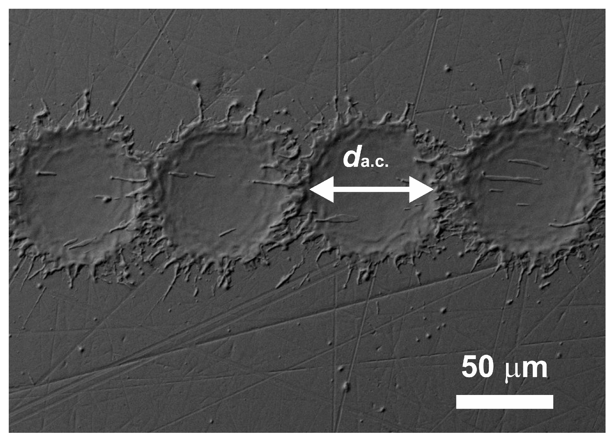
Figure 1. SEM image of ablation craters formed due to a single action of a laser pulse on the X16CrNi25-20 steel surface. Laser pulse parameters: a wavelength of 1064 nm, a duration of 120 ns, a frequency of 110 kHz, and a pulse energy of 0.43 mJ.
Applsci 13 00095 g001
Figure 2. Schematic representations of a texture configuration in the form of parallel microchannels developed at the planning stage. (a) AB, (b) A2B, and (c) 2AB. A is the width of the surface area that is not subject to laser radiation and B is the width of the surface area processed by laser radiation.
Applsci 13 00095 g002
Figure 3. Experimental setup of a mixed heat supply to a fuel droplet. 1—tubular muffle furnace; 2—ceramic tube; 3—fuel droplet; 4—steel; 5—tripod; 6—coordinate mechanism; 7—control unit for coordinate mechanism; 8—high-speed video camera; 9—spotlight; and 10—computer.
Applsci 13 00095 g003
Figure 4. Experimental setup of a conductive heat supply to a fuel droplet. 1—modified steel surface; 2—electromagnetic inductor; 3—induction spiral; 4—control unit for inductor; 5—thermal imaging camera; 6—chiller; 7—fuel droplet; 8—holder; 9—high-speed video camera; and 10—spotlight.
Applsci 13 00095 g004
Figure 5. Typical frames of video recording processing to determine the ignition and combustion characteristics of fuel droplets. Characteristics determined for a mixed heat supply were ds (a), τd (b), Dmax (c), and N (d). Characteristics determined for a conductive heat supply were τd (e), Dmax (f), and N (g).
Applsci 13 00095 g005
Figure 6. SEM images of polished (a) and laser-modified steel surfaces. (b) AB, (c) A2B, and (d) 2AB. The gray frame represents a typical area on the surface. The red frame represents the textured area after processing by laser radiation. The green and blue frames represent the non-textured areas.
Applsci 13 00095 g006aApplsci 13 00095 g006b
Figure 7. The ignition delay time of fuel droplets versus the projection area of the fuel droplet/heating surface interface under a mixed heat supply.
Applsci 13 00095 g007
Figure 8. The number of puffing initiations (a), the maximum size of the burnout region (b), and the time of complete burnout (c) of liquid fuels under a mixed heat supply.
Applsci 13 00095 g008
Figure 9. Ignition delay times of fuel droplets (liquid oil in the usual state, emulsion, and slurry) under a conductive heat supply.
Applsci 13 00095 g009
Figure 10. The number of puffing initiations (a), the maximum size of the burnout region (b), and the time of complete burnout (c) of liquid fuels under a conductive heat supply to the P, AB, A2B, and 2AB heating surfaces.
Applsci 13 00095 g010
Table 1. Characteristics of components in composite fuel.
ComponentWa, %Ad, %Vdaf, %Qas,V, MJ/kg
Engine oil0.280.7810.244.00
Coal processing waste
(filter cake)
35.0040.520.24
Table 2. The 3D roughness parameters of steel surfaces.
Steel SurfaceUnprocessed Local RegionProcessed Local Region
Sa, µmSz, µmSdr, %Sa, µmSz, µmSdr, %
AB3.4248312.492412
A2B3.3934282.372311
2AB3.4759442.512411
Steel SurfaceA Typical Surface Area Containing Unprocessed and Processed Regions
Sa, µmSz, µmSdr, %
P1.627<1
AB8.28171104
A2B7.7824589
2AB8.05172127
Table 3. Contact diameters of fuel droplets measured during droplet spreading parallel (d↕) and perpendicular (d↔) to microchannels on steel surfaces.
Fuel
SurfaceOilEmulsionSlurry
d↕, mmd↔, mmd↕, mmd↔, mmd↕, mmd↔, mm
P10.2 ± 0.29.2 ± 0.17.6 ± 0.1
AB24.0 ± 0.27.3 ± 0.119.5 ± 0.16.5 ± 0.112.0 ± 0.15.8 ± 0.1
A2B24.5 ± 0.27.4 ± 0.119.8 ± 0.16.6 ± 0.112.6 ± 0.15.9 ± 0.1
2AB24.7 ± 0.27.7 ± 0.121.0 ± 0.16.8 ± 0.113.0 ± 0.16.4 ± 0.1
Disclaimer/Publisher’s Note: The statements, opinions and data contained in all publications are solely those of the individual author(s) and contributor(s) and not of MDPI and/or the editor(s). MDPI and/or the editor(s) disclaim responsibility for any injury to people or property resulting from any ideas, methods, instructions or products referred to in the content.