Article

Environment Perception with Chameleon-Inspired Active Vision Based on Shifty Behavior for WMRs

College of Engineering, Shenyang Agricultural University, Shenyang 110866, China
*
Author to whom correspondence should be addressed.
Appl. Sci. 2023, 13(10), 6069; https://doi.org/10.3390/app13106069
Submission received: 8 April 2023 / Revised: 7 May 2023 / Accepted: 11 May 2023 / Published: 15 May 2023
(This article belongs to the Section Robotics and Automation)

Abstract

:

Featured Application

Inspired by the visual behavior mechanism of the chameleon predation process, this paper proposes a chameleon-inspired active-vision-based environment perception strategy based on a shifty-behavior mode for mobile robots. It achieved the reproduction of the visual behavior of chameleons in the vision system of mobile robots with satisfactory results, which is of great significance for improving the environmental perception ability and adaptability of mobile robots.

Abstract

To improve the environment perception ability of wheeled mobile robots (WMRs), the visual behavior mechanism of the negative-correlation motion of chameleons is introduced into the binocular vision system of WMRs, and a shifty-behavior-based environment perception model with chameleon-inspired active vision for WMRs is established, where vision–motor coordination is achieved. First, a target search sub-model with chameleon-inspired binocular negative-correlation motion is built. The relationship between the rotation angles of two cameras and the neck and the camera’s field of view (FOV), overlapping angle, region of interest, etc., is analyzed to highlight the binocular negative-correlation motion compared with binocular synchronous motion. The search efficiency of the negative-correlation motion is doubled compared with binocular synchronous motion, and the search range is also greatly improved. Second, the FOV model of chameleon-inspired vision perception based on a shifty-behavior mode is set up. According to the different functional requirements of target searching and tracking stages, the shift of the robot visual behavior is analyzed from two aspects, measuring range and accuracy. Finally, a chameleon-inspired active-vision-based environment perception strategy for mobile robots is constructed based on the shifty-behavior mode, and experimental verification is deployed, which achieves the reproduction of the visual behavior of chameleons in the vision system of mobile robots with satisfactory results.

1. Introduction

To enable robots to perceive and acquire environmental information with their eyes, such as with humans or animals, and to quickly and accurately identify and track targets, people have attempted various methods to simulate human or animal eyes or reproduce intelligent behaviors related to biological vision, leading to the emergence of machine vision technology [1,2,3]. Active vision, as opposed to traditional passive vision, emphasizes the activity and selectivity of the visual information acquisition and processing process, i.e., the interaction ability between the visual system and its environment [4,5,6]. A chameleon is called a “lion on the ground” because its visual system plays an important role in its defense and predation. A chameleon’s two eyes can move independently without constraint for panoramic observation, and they can also move synchronously for binocular stereo vision, accurately measuring the depth information of prey, thus allowing its tongue to precisely capture the prey [7,8,9,10]. The independent eye movements of a chameleon are shown in Figure 1.
Many scholars have studied the specificity of the behavioral mechanism of the vision system of chameleons. Ott and Schaeffel noted that, unlike other vertebrates, the eyes of chameleons have a negative focal mechanism that allows them to calculate target information more precisely [11,12,13]. In addition, Ott pointed out through further studies that during the sweeping of the environment by a chameleon’s two eyes with the high-speed motion of the prey, the two eyes move with different amplitudes and alternate between fixed-focus and non-focus states. Therefore, when a chameleon rapidly searches for targets in the environment, the motions of its two eyes are independent of each other, and this is known as the negative-correlation saccade pattern, which greatly improves the efficiency of scanning the environment. In addition, since a chameleon has relative motion between its eyes and head, the environmental search range of a chameleon can be further improved by the dual motion of the head and eyes. Avni used an experimental design to study the gaze direction of the eyes of chameleons when scanning the environment for prey targets, and the experimental results confirmed that the eyes of chameleons obeyed a “negative-correlation” motion pattern when scanning the environment for targets [14,15]. In addition, Prasad applied the idea of a chameleon’s eyes to a missile propulsion controller for obstacle avoidance [16]. Xu studied the coordinated motion of a mobile robot equipped with a chameleon-inspired vision system during target tracking [17]. Zhao from Yanshan University applied it to a compass parallel robot [18,19]. Zhou and Tsai applied the binocular negative-correlation-motion mechanism of chameleons to a surveillance system to improve the flexibility of surveillance [20,21]. Chen constructed a vision-based pose alignment platform inspired by a chameleon for multi-position prey capture and a concept verification demonstration [22].
In previous research, most robotic vision systems have adopted the binocular cooperative motion search mode, such as the Mars rover and lunar rover. At present, the mainstream technologies of binocular vision include stereo vision, structured light, and time of flight (TOF). Based on the principle of the human oculomotor nervous system, Liu proposed an algorithm to simulate the human oculomotor system using a binocular motion system [23]. Zhang designed the device and algorithm of bionic eye anthropomorphic bionic vision and realized the function of six-degrees-of-freedom vision control and binocular stereo vision control [24,25]. To overcome the shortcomings of narrow binocular vision and low monocular depth perception accuracy, Wang and Zou proposed a method to simulate the pursuit and saccade actions of the human visual system, which improves the accuracy of 3D coordinates obtained at the best observation position [26,27]. In response to the depth measurement errors generated by bionic eyes, Wang proposed some effective bionic eye design guidelines [28]. Fan and Liu proposed a 3D triangulation method based on eye gaze to improve the measurement error of bionic eyes [29]. Chen proposed an integrated dual attitude calibration method to obtain accurate and stable head–eye parameters and kinematic models [30]. In addition, many scholars have designed different forms of humanoid vision systems. Chen developed a bionic compound eye based on the neural network of a fiber bundle stereo, which can quickly and accurately acquire the 3D spatial information of a target [31]. To improve the lack of rotational freedom in most bionic eyes, Chen and Wang designed a three-degrees-of-freedom tandem-parallel vision mechanism that enables the eccentric-free spherical motion of a bionic eye [32]. In addition, machine learning algorithms are widely used in the field of image recognition and trajectory tracking for robots, which can significantly improve the accuracy and stability of control [33,34,35,36].
When autonomous mobile robots work in the field, one of their most essential tasks is to use their binocular vision system to quickly scan the surroundings over a wide area to discover and target an object of interest. Improving the search efficiency and expanding the search range is a tricky and urgent problem. In previous studies, most of the robot binocular vision systems have used the following two search modes: (1) the cameras are fixed, and the mobile platform rotates to search; (2) the two cameras synchronously rotate to search, which is inspired by the human visual system. These two search modes have a large binocular correlation, symmetry, and a large overlapping field of view, so the search efficiency is low, and the search range is limited. In contrast, the binocular independent-motion vision system of a chameleon can realize both independent motion for panoramic rapid scanning and cooperative motion for stereo vision, which has absolute advantages in rapid target searching. However, the current research on the visual behavior of chameleons mainly focuses on the experimental study of the negative-correlation-motion mechanism and its application in monitoring systems. There are still few applications for the visual behavior mechanism of chameleons in the vision systems of wheeled mobile robots (WMRs).
Therefore, in this paper, according to the visual function requirements of the robot at different stages, we propose a bionic binocular active-vision-based environment perception model for WMRs equipped with a binocular vision system based on shifty behavior and inspired by the predation process of chameleons, which can improve the search efficiency and expand the search range. The shifty-behavior model emphasizes the shift from one behavior to another to achieve different functional goals, and in this paper, it refers to the behavior shift of the vision system from binocular negative-correlation motion to binocular synchronous motion in order to achieve a wide range of rapid environmental scanning and the accurate localization and tracking of targets. In this process, the coordinated motion of the robot body and the vision system with the neck is achieved, which is referred to as vision–motor coordination, which is an important functional requirement in active-vision environment perception.

2. Visual Perception Modelling in Chameleon-Inspired Shifty-Behavior Mode for WMRs

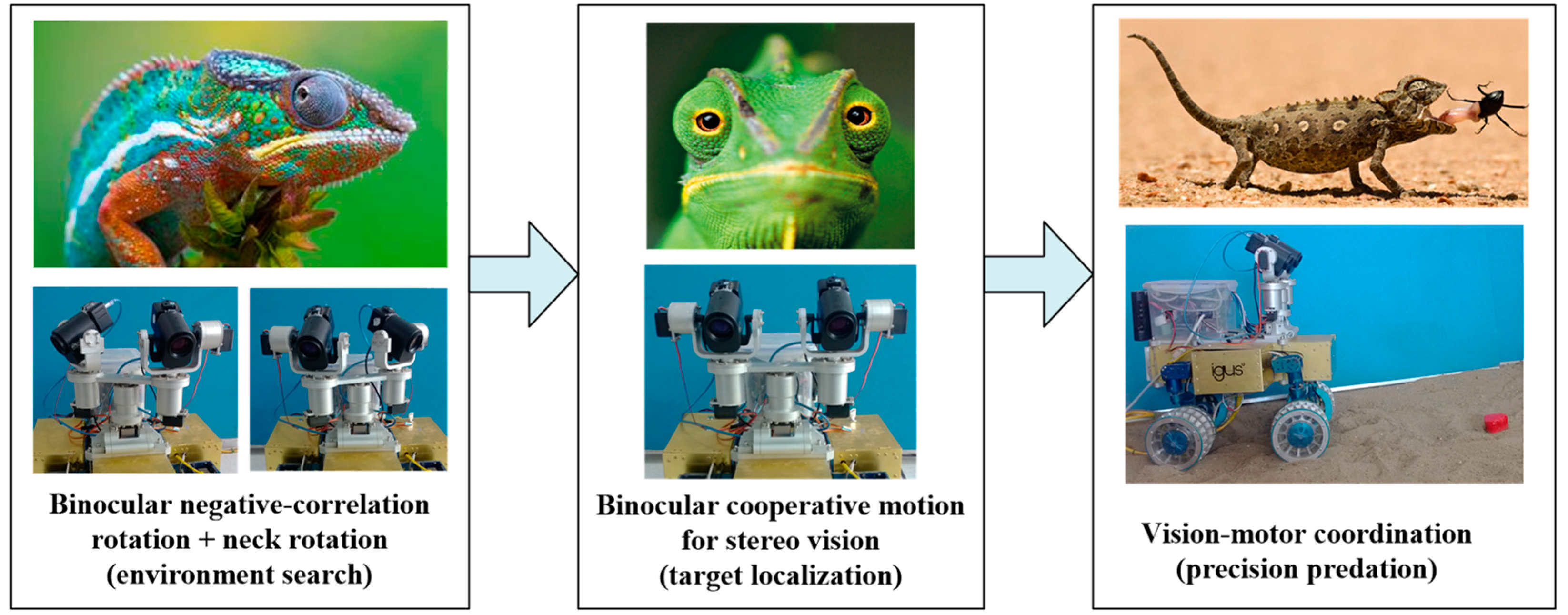
The construction process of the chameleon-inspired vision system for WMRs is shown in Figure 2. First, considering that a chameleon’s eyes have zoom and rotation characteristics, which can achieve approximately 180° rotation in the horizontal direction and 90° rotation in the vertical direction, and they have negative-correlation motion characteristics, dual PTZ cameras were used to imitate the visual behavior mechanism of chameleons. Furthermore, the rotation of the neck can further improve the search range and search flexibility. Second, once a chameleon finds a target, it will first lock on to the target with one eye, and then quickly adjust the other eye to focus on the target, thus forming binocular stereo vision to accurately determine the location of the target. Finally, through real-time feedback from the vision system, the robot achieved an accurate tracking of the target.
In the field of mobile robots, the optical zoom type has obvious advantages. Therefore, an optical zoom lens was used in this paper. To adapt to the robot’s working requirements, an avenir-SSL06036M 6× zoom lens was selected as the robot lens in this paper. Zoom, focus, and iris were controlled by a 12v voltage signal. To realize a more convenient connection with industrial computers and reduce the number of intermediate transformation steps, a CMOS camera with a USB interface was chosen. To match the lens, a camera with a target surface size of 1/3″ was chosen. To adapt to the mobile robot tracking target, the update frequency of CMOS was maintained above 30 fps to ensure a resolution of 320 × 240, thus ensuring the success rate of target searching and tracking. Therefore, a Suntime-200 industrial camera was selected in this paper. The specific parameters of the lens and CMOS are shown in Table 1.
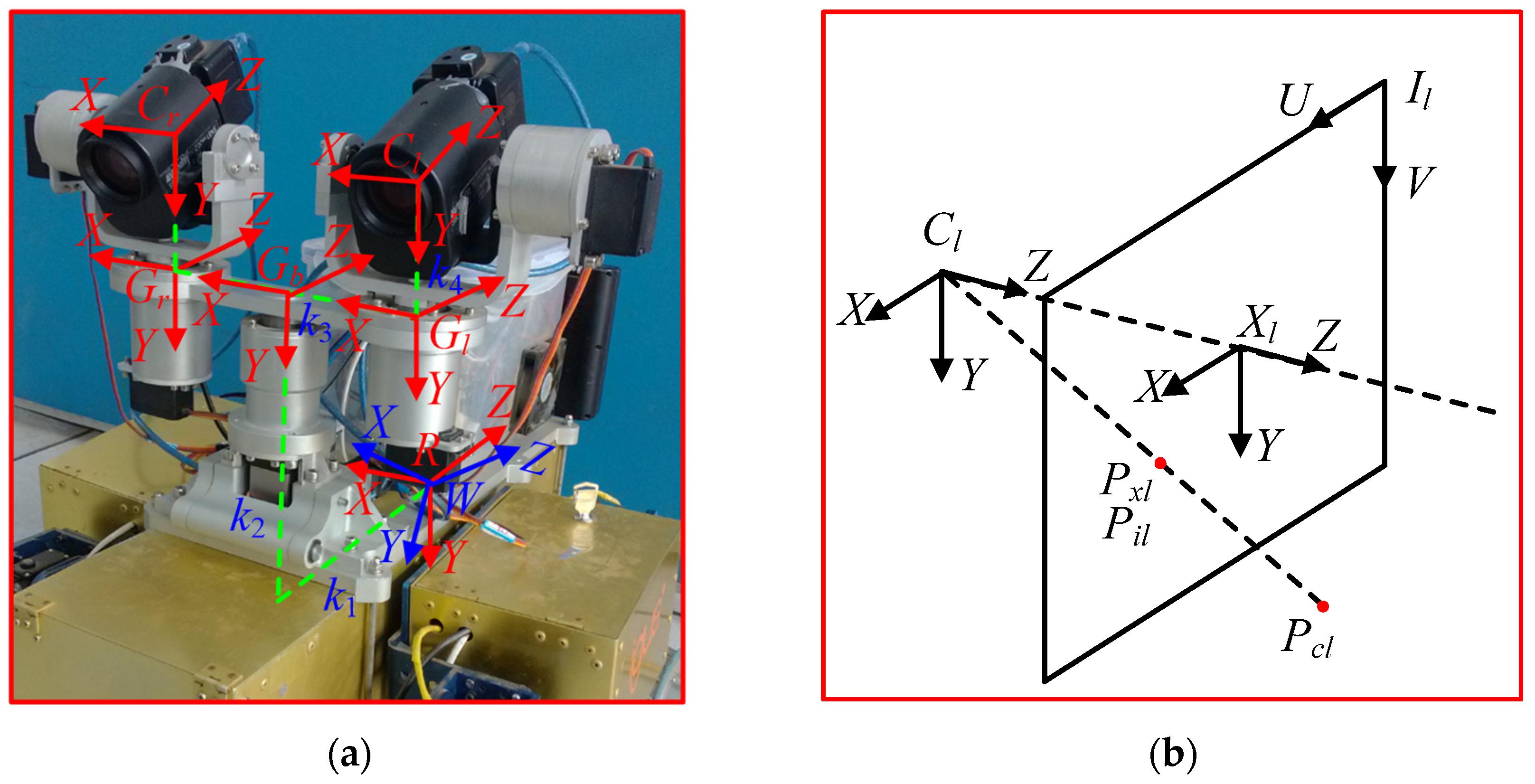
When a mobile robot with a chameleon-inspired vision system searches for targets, it involves changes in the position and the orientation of the camera imaging and the PTZ servo mechanism. Therefore, according to the constructed vision platform, a coordinate system was established as shown in Figure 3, and all coordinate systems conformed to the right-hand rule [37].
In the above figure, W , R denotes the world coordinate system and the robot body coordinate system, both located at the geometric midpoint of the body differential mechanism; G b denotes the neck coordinate system, located at the center of the PTZ beam; G l , G r denote the left and right PTZ coordinate system, located at the rotation centers of the left and right sides of the PTZ; C l , C r denote the left and right camera coordinate system, located at the optical centers of the left and right cameras; X l , X r denote the left and right camera imaging coordinate system; and I l , I r denote the left and right camera image coordinate system; P c l x c l , y c l , z c l denotes the coordinates of the target point in the left camera coordinate system; P x l x x l , y x l denotes the coordinates of the target point under the left camera imaging coordinate system; P i l u , v denotes the coordinates of the target point under the left camera image coordinate system.
During the process of environmental perception using their eyes, chameleons adopt a shifty-behavior mode according to the functional requirements at different stages. In the target search stage, the binocular negative-correlation motion mechanism with the wide-angle camera mode is used to perform a rapid wide-range scanning of the environment. In the target tracking stage, once the target is detected, the two eyes are coordinated and synchronized to achieve stereo vision, which precisely measures the depth information of the target and makes the outstretched tongue catch the prey just right, and the focal length is appropriately increased to improve the measurement accuracy. Based on the visual behavioral mechanism of chameleons, a visual perception model in the chameleon-inspired shifty-behavior mode for WMRs was established, as shown in Equation (1).
P v S n g ϕ n g b , φ n g l , φ n g r , θ n g l , θ n g r , f n g F n g v , C n g , B c o ϕ c o b , φ c o l , φ c o r , θ c o l , θ c o r , f c o F c o v , D c o   s . t . ϕ b min ϕ b ϕ b max φ l min φ l φ l max φ r min φ r φ r max θ l min θ l θ l max θ r min θ r θ r max f min f f max
where P v · denotes the visual perception model in the chameleon-inspired binocular shifty-behavior mode for WMRs, S n g · denotes the target search model with the chameleon-inspired binocular negative-correlation motion, ϕ n g b , φ n g l , φ n g r , θ n g l , θ n g r , f n g denotes the action set of the dual PTZ vision system in the target search stage, and F n g v , C n g denotes the output set of the vision system in the target search stage, and the action set determines the output set. F n g v denotes the field of view (FOV) acquired by the chameleon-inspired binocular negative-correlation motion, C n g denotes the target features detected by the selective attention algorithm, B c o · denotes the target tracking model with the binocular synchronous motion, ϕ c o b , φ c o l , φ c o r , θ c o l , θ c o r , f c o denotes the action set of the dual PTZ vision system in the target tracking stage, and F cov , D c o denotes the output set of the vision system in the target tracking stage, and the action set determines the output set. F c o v denotes the FOV acquired by the binocular synchronous motion, and D c o denotes the depth information of the target acquired by the binocular stereo vision.

3. Target Search Modelling with Chameleon-Inspired Binocular Negative-Correlation Motion for WMRs

For the chameleon-inspired vision system of WMRs, a binocular negative-correlation motion search model was established to analyze the negative-correlation-motion behavior of the two eyes and the synchronous-motion behavior of the two eyes and the neck when the vision system is searching for a target. The relationship between the rotation angles of the two cameras and the neck and the FOV, the overlapping angle, and the region of interest of the cameras was quantified. To compare with the chameleon-inspired binocular negative-correlation-motion search model, a binocular synchronous-motion search model was established. The direction of the camera rotating to the right and upward was defined as the positive direction.
S ϕ b , φ l , φ r , θ l , θ r , f , M o d ( j = 0 , 1 ) F v , C o   s . t . ϕ b min ϕ b ϕ b max φ l min φ l φ l max φ r min φ r φ r max θ l min θ l θ l max θ r min θ r θ r max f min f f max
where S · denotes the target search model in different search modes, ϕ b , φ l , φ r , θ l , θ r , f , M o d ( j = 0 , 1 ) denotes the action set of the dual PTZ vision system in the target search phase, and F v , C o denotes the output set of the vision system in the target search phase, and the action set determines the output set. ϕ b , φ l , φ r , θ l , θ r denotes the rotation angle of the neck in the horizontal plane and the rotation angles of the left and right cameras in the horizontal plane and the vertical plane, respectively. f denotes the focal length of the camera. M o d ( j = 0 , 1 ) denotes the chameleon-inspired binocular negative-correlation-motion and binocular synchronous-motion search modes, respectively.
The relationship between the rotation angles of the two cameras and the neck and the FOV, overlapping angle, and region of interest of the cameras is shown in Equation (3).
R = ϕ b , φ l , φ r , θ l , θ r , M o d j = 0 , 1     = R α , β , δ , r , s , Ψ × Φ , M o d j = 0 , 1 , s . t . ϕ b min ϕ b ϕ b max φ l min φ l φ l max φ r min φ r φ r max θ l min θ l θ l max θ r min θ r θ r max
Therefore, the number of rotations of the vision system in the horizontal and vertical planes can be deduced from the FOV, the overlapping angle, the region of interest, and the search mode used by the two cameras [38], as shown in Equation (4).
2 α r n g 2 δ r n g 1 = Ψ 0 + α β s n g δ s n g 1 = Φ 0 + β , ( j = 0 ) α r c o δ r c o 1 = Ψ 0 + α β s c o δ s c o 1 = Φ 0 + β , ( j = 1 )
Subsequently, the rotation angles of the two cameras and the neck in the two search modes to achieve scanning of the horizontal region of interest can be obtained as follows:
ϕ n g b + φ n g i = ( 1 ) c 0 . 5 Ψ 0.5 2 p n g 1 α + p n g 1 δ , p n g = r n g , r n g 1 , , 1 , ( j = 0 ) φ c o i = 0 . 5 Ψ 0.5 2 p c o 1 α + p c o 1 δ ,   p c o = r c o , r c o 1 , , 1 , ( j = 1 )
where i l , r denotes the camera label, and c = 0 , 1 denotes the left and right camera labels. For the binocular negative-correlation-motion search mode with neck rotation, the best combination of rotation angles ϕ n g b with φ n g l , φ n g r are obtained by the rotation optimization model based on a genetic algorithm [39].
Similarly, the rotation angles of the two cameras in the vertical plane in both search modes can be obtained as follows:
θ i = 0 . 5 Φ 0.5 2 q 1 β + q 1 δ , q = s , s 1 , , 1 , ( j = 0 , 1 )
where Ψ × Φ denotes the region of interest of the robot, α , β denotes the horizontal and vertical field-of-view angles of the cameras, and they are the same, and δ denotes the overlapping angle of the FOV, and they are equal for the horizontal and vertical FOV.
Through the modeling analysis of the above two search modes, it can be found that, on the one hand, for the camera’s rotation angles in the horizontal plane, in the case of the same size of the horizontal region of interest, first, the chameleon-inspired binocular negative-correlation-motion search mode reduces the camera’s rotation times by twice as much as the binocular synchronous-motion search mode, which means that not only can the power consumption of the camera servos be reduced twice but also the search efficiency is increased twice. Second, the number of images processed in the binocular negative-correlation-motion search mode is half that of the binocular synchronous-motion search mode, which can significantly reduce the burden of image processing for the robot computer and improve the processing efficiency. Finally, the neck increases the degrees of freedom of the vision system, making the same search range be accomplished by the rotation of three axes, thus improving the search efficiency. This rotation combination of the neck and cameras makes the search more flexible and the camera’s rotation angles smaller when scanning the same range, i.e., the vision system has a larger search range when the camera reaches its rotation limit. On the other hand, for the camera’s rotation angles in the vertical plane, in the case of the same size of the vertical region of interest, although there is no difference between the two modes in the case of normal camera operation, if the camera is once contaminated then the chameleon-inspired binocular negative-correlation-motion mode can give full play to its advantage of negative-correlation motion to achieve the complementation of visual contamination.

4. Modelling of FOV in Chameleon-Inspired Active Vision Based on Shifty-Behavior Mode for WMRs

The FOV in the chameleon-inspired active-vision shifty-behavior mode in different stages is modeled for mobile robots, including the FOV model of binocular negative-correlation motion for target searching and the FOV model of binocular synchronous motion for target tracking. Under these two FOV models with different visual perception behaviors, the spatial variations in the monocular FOV, the binocular overlapping FOV, and the binocular merging FOV of the vision system are analyzed. In addition, the quantitative relationships between the vision system parameters and the FOV and the resolution of the vision system are analyzed to show the behavioral shift in the vision system based on different functional requirements in the target search and target tracking stages. The binocular vision system based on the shifty behavior has a better extension of the measurement range and a better adaptivity in terms of measurement accuracy than the traditional binocular vision system.

4.1. FOV Model with Binocular Synchronous Motion

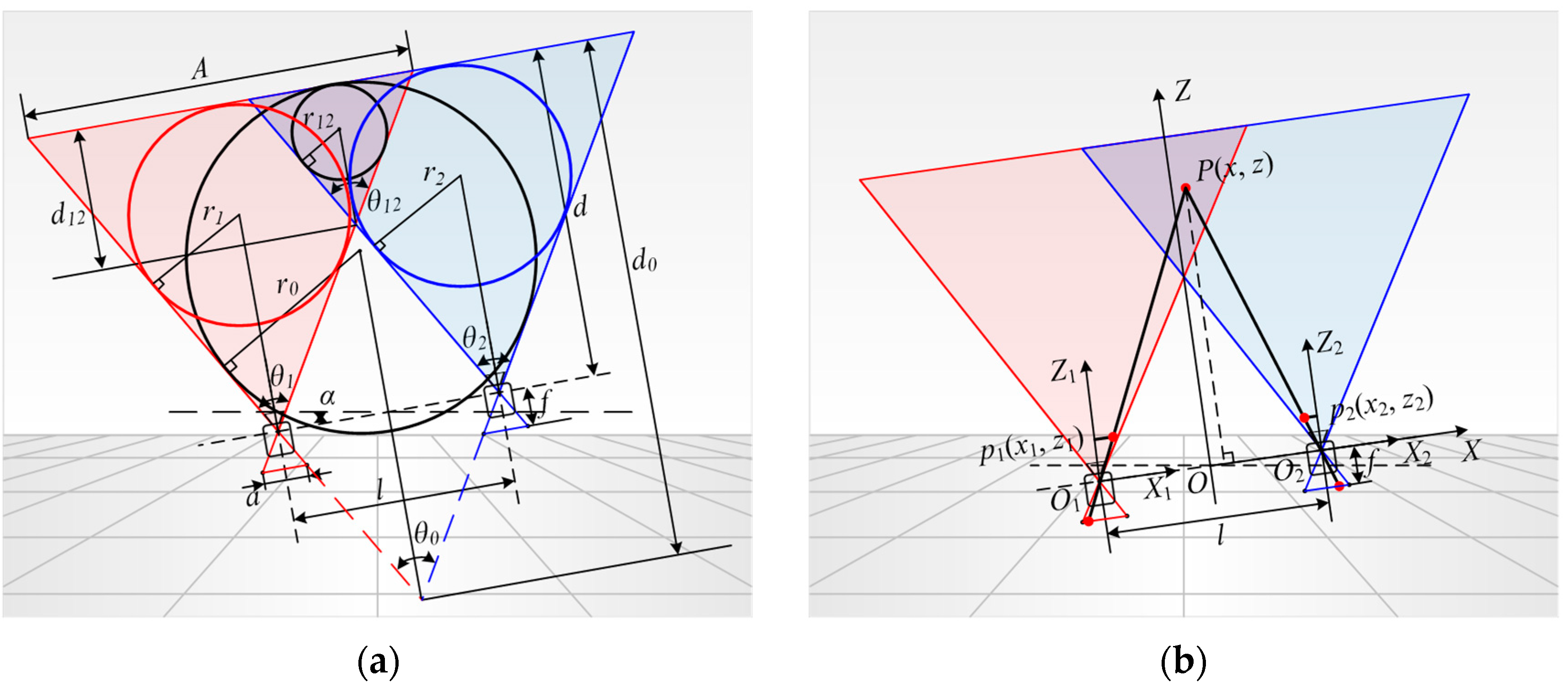
The FOV model is shown in Figure 4 when the cameras are in synchronous motion, and the PTZ beam carrying the two cameras is rotated α to the left around its central axis, resulting in the two cameras rotating α to the left simultaneously. The direction of the beam rotating to the right around its central axis is defined as positive. In this paper, the FOV of the binocular vision system was analyzed by taking the horizontal FOV as an example. The parameters of the binocular visual system of WMRs are shown in Table 2.
To reflect the size change relationship of the FOV, the inner tangent circle of the FOV defined to represent the size of the FOV [40], as shown in Figure 4a. In this binocular synchronous motion mode, the radii of the inner tangent circles of the monocular horizontal FOV, the binocular horizontal overlapping FOV, and the binocular horizontal merging FOV are calculated by the following equations:
r 1 = r 2 = a d / 2 a 2 / 4 + f 2 + a r 12 = a d l f / 2 a 2 / 4 + f 2 + a r 0 = a d + l f / 2 a 2 / 4 + f 2 + a
To analyze the measurement accuracy of the binocular vision system, the resolution is analyzed. Figure 4b shows the imaging model of the binocular vision system, with O X Z representing the vision system’s coordinate system and O 1 X 1 Z 1 , O 2 X 2 Z 2 representing the left and right camera coordinate systems, respectively. Assuming that the image element size of CMOS is Δ w , then the resolution Δ X , Δ Z of the vision system in the X , Z direction in the binocular synchronous motion mode is given by the following equations:
Δ X = min z f Δ w , z f Δ w Δ Z = min 2 z 2 f l + 2 x Δ w , 2 z 2 f l 2 x Δ w

4.2. FOV Model with Binocular Negative-Correlation Motion

In the chameleon-inspired binocular negative-correlation-motion mode, the two cameras are rotated α 1 , α 2 around their optical axes to the left and right, respectively, where α 1 = α 2 = α . The FOV model is shown in Figure 5.
In the binocular negative-correlation-motion mode, the equations for the radius of the inner tangent circle of the binocular horizontal overlapping FOV and the binocular horizontal merging FOV are shown below:
r 12 = d sin arctan a 2 f α l 2 cos arctan a 2 f / cos α + sin arctan a 2 f α r 0 = d sin arctan a 2 f + α + l 2 cos arctan a 2 f / cos α + sin arctan a 2 f + α
In addition, the resolutions Δ X , Δ Z of the vision system in the X , Z directions are shown in Equation (10):
Δ X = min z x + 0.5 l + z tan α sin α cos α 2 z f cos 2 α Δ w , z 0.5 l x + z tan α sin α cos α 2 z f cos 2 α Δ w Δ Z = min z cos α x + 0.5 l sin α 2 f x + 0.5 l Δ w , z 0.5 l x + z tan α sin α cos α 2 f 0.5 l x cos 2 α Δ w

4.3. Simulation Analysis of FOV Model

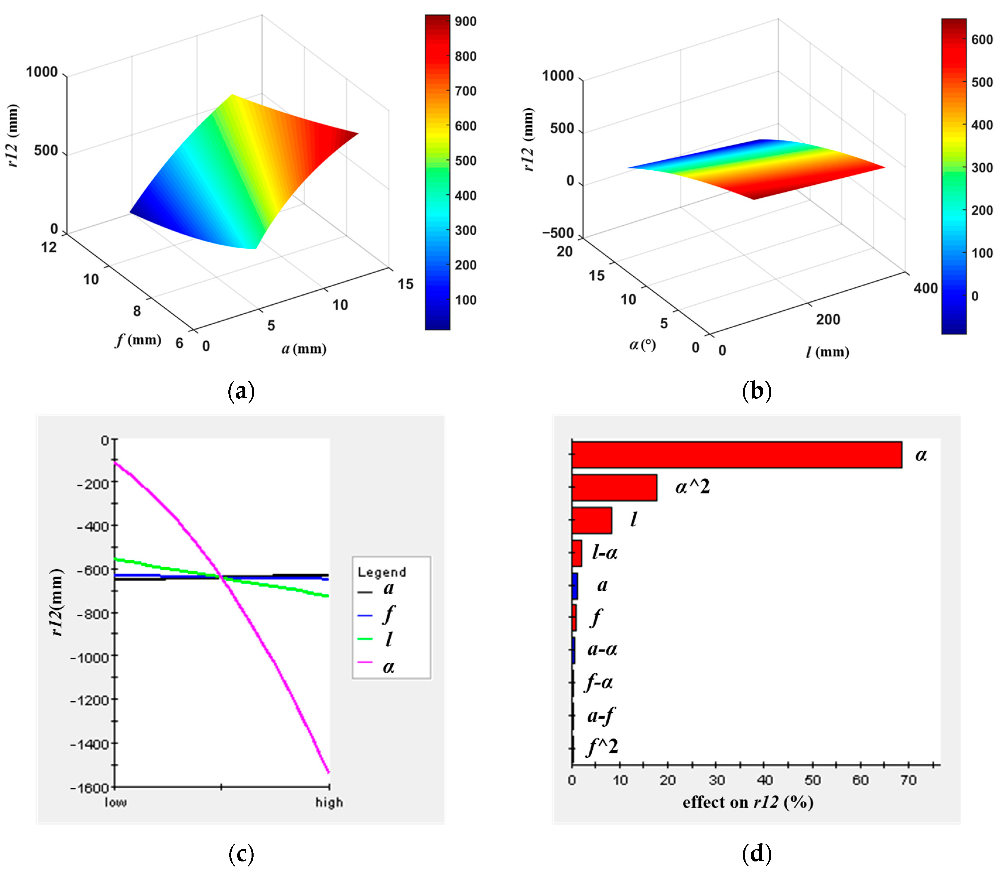
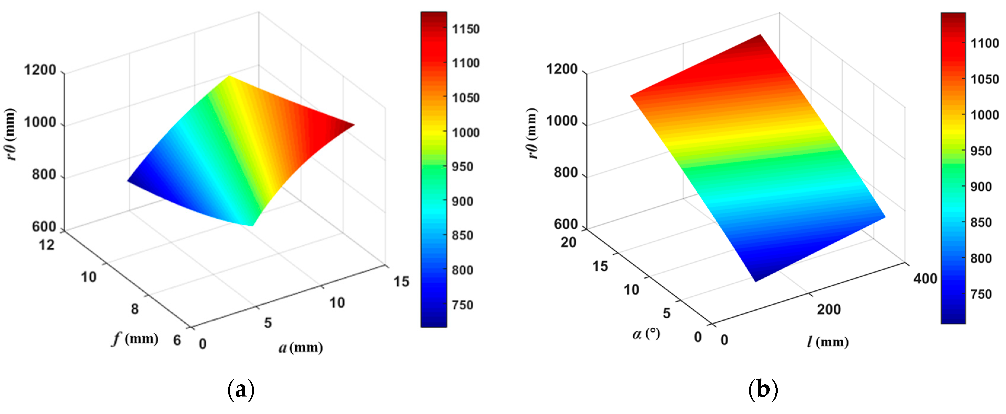
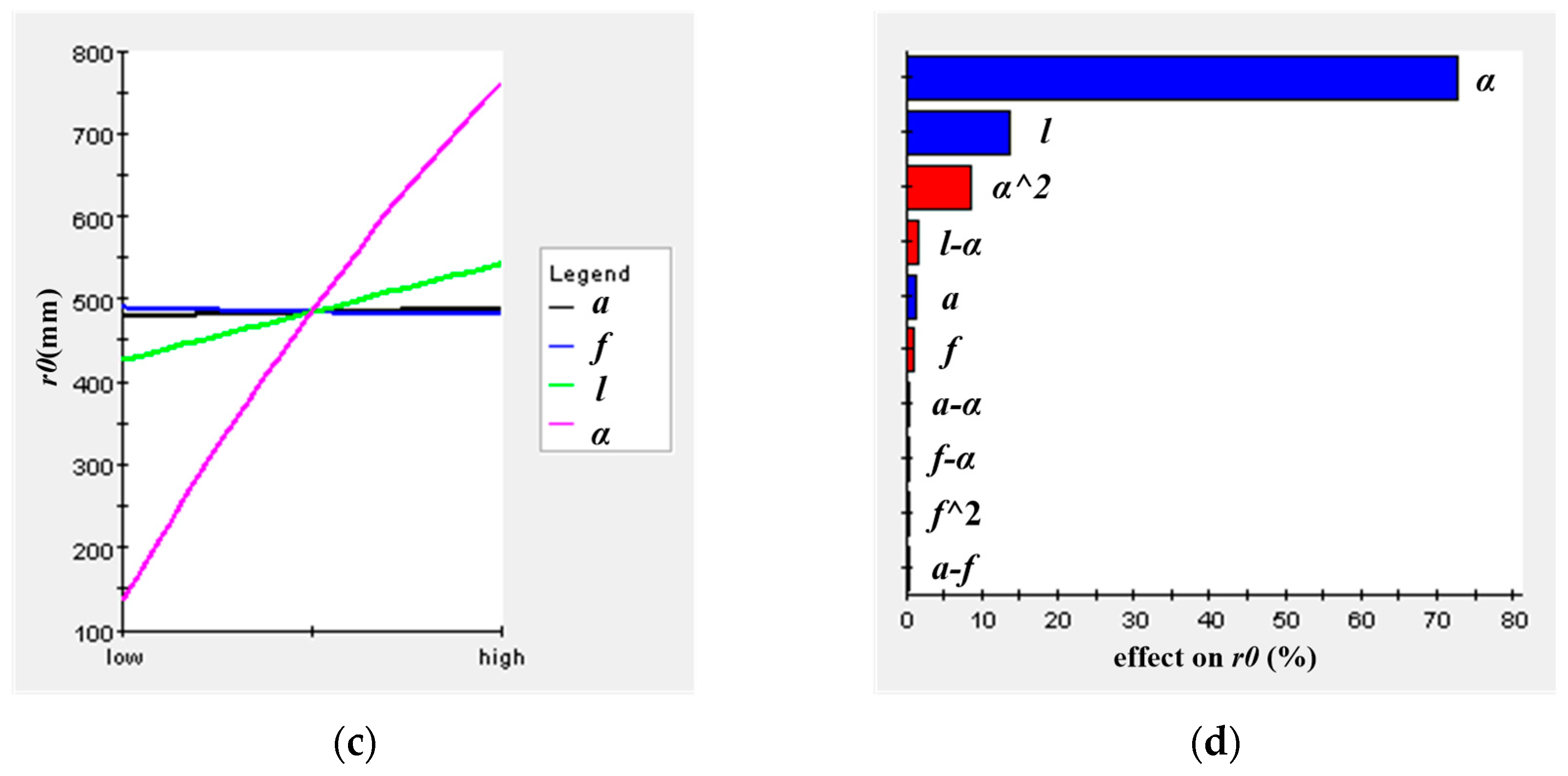
Through the above analysis, it can be found that the FOV model in the binocular negative-correlation-motion target search stage introduces a binocular negative-correlation rotation angle compared to that in the binocular synchronous motion target tracking stage, so the simulation analysis from the measurement range and accuracy for the binocular negative-correlation-motion FOV model is carried out without any loss of generality. According to Equation (9), the relationship surfaces of the binocular horizontal overlapping FOV and binocular horizontal merging FOV with the parameters of the vision system as well as the main effect diagram and Pareto diagram [41,42] obtained by orthogonal experimentation can be obtained, as shown in Figure 6 and Figure 7.
As shown in Figure 6, the rotation angles of the two cameras with negative-correlation motion have a very significant negative effect on the change in the size of the binocular horizontal overlapping FOV, with an effect rate of about 68%. Therefore, if we want to increase the binocular horizontal overlapping FOV, we can reduce the rotation angles of the negative-correlation motion of the two cameras. Therefore, in the target tracking stage, the binocular synchronous-motion mode is used, where the rotation angles of the two cameras with negative-correlation motion is 0 in order to ensure an effective FOV of sufficient size.
As shown in Figure 7, the rotation angles of the two cameras with the negative-correlation motion have a very significant positive effect on the change in the size of the binocular horizontal merging FOV, with an effect rate of about 73%. Therefore, if we want to increase the binocular horizontal merging FOV, we can increase the rotation angles of the two cameras with negative-correlation motion. However, to ensure the continuity of the search area, the rotation angles of the two cameras with negative-correlation motion should not be too large.
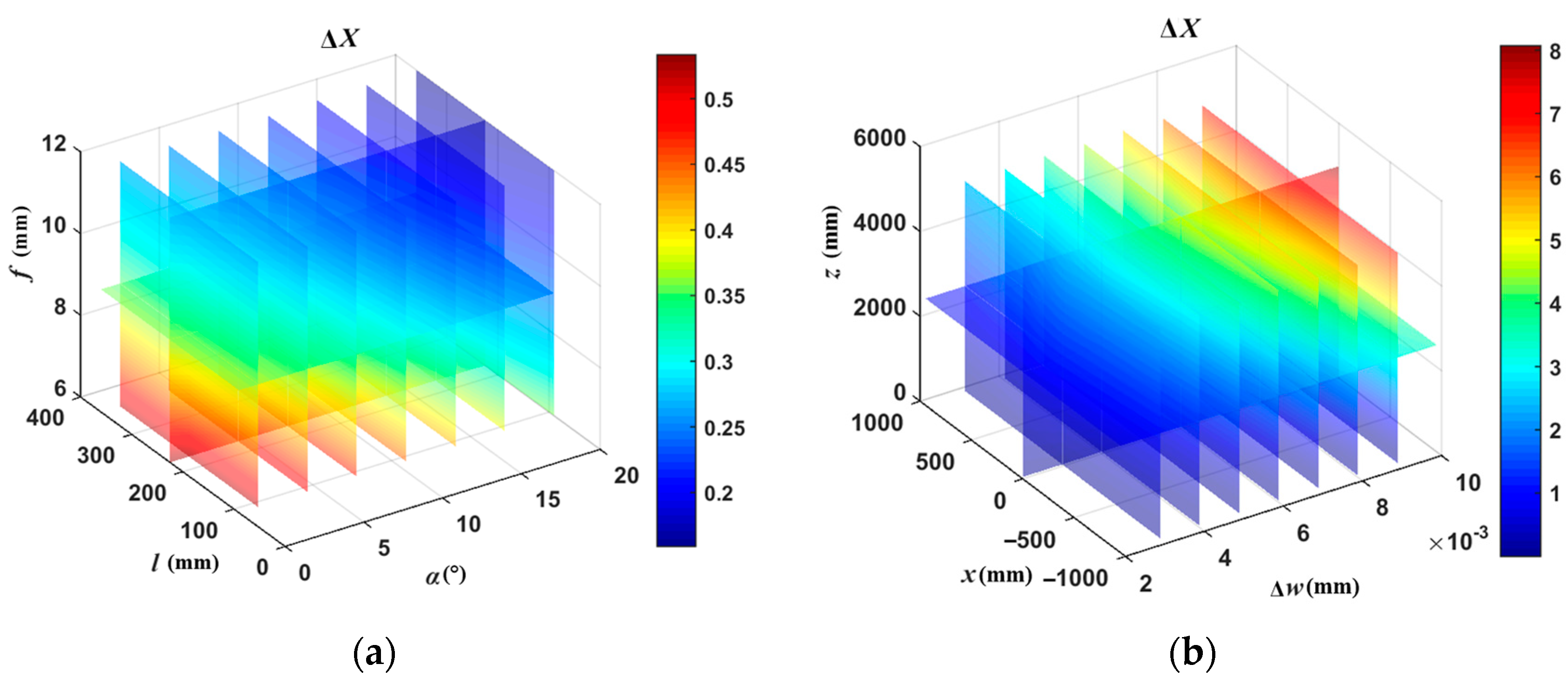
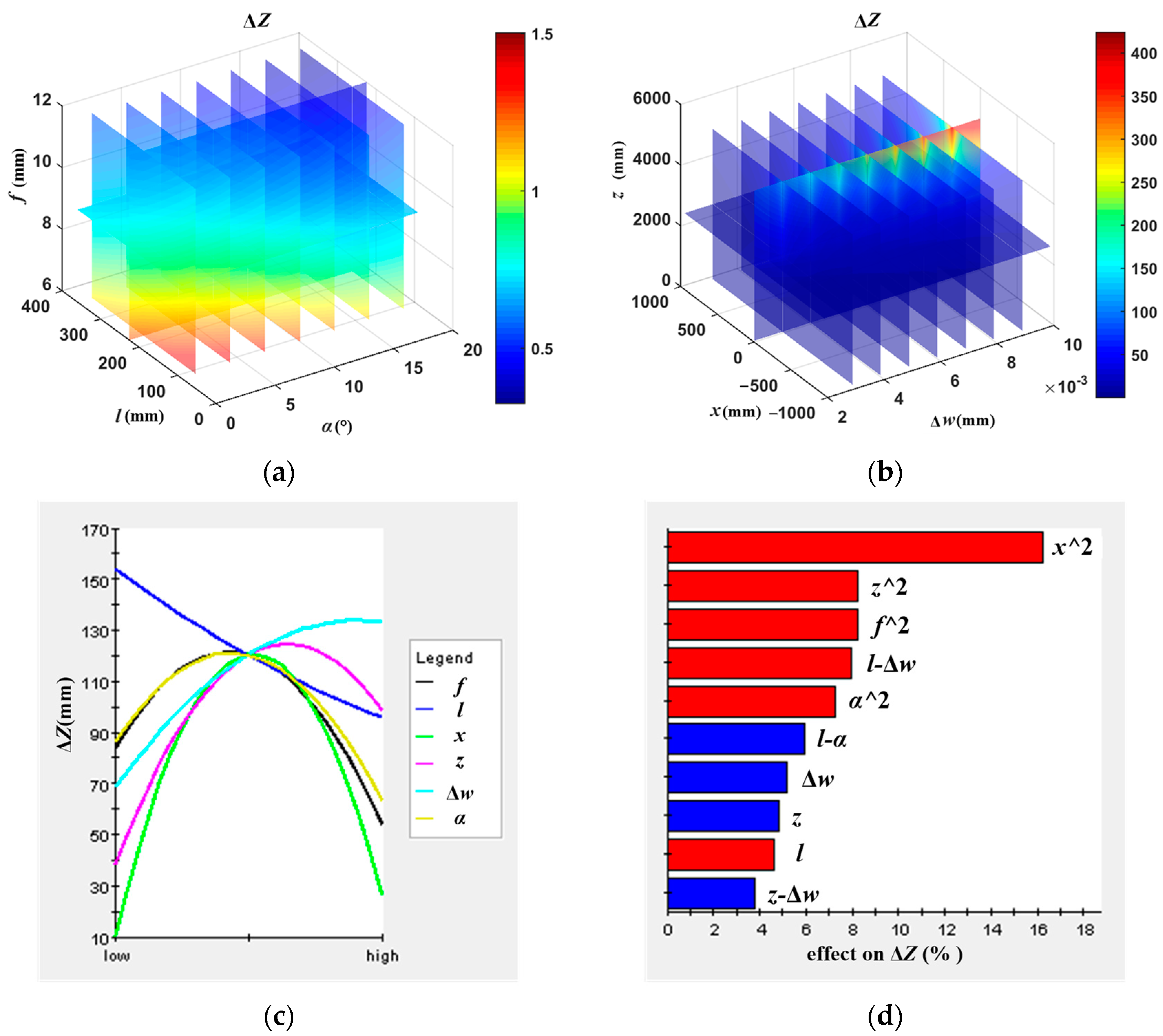
According to Equation (10), the relationship surfaces of the resolution in the X and Z directions with the parameters of the vision system can be obtained, as can the main effect diagram and Pareto diagram obtained by orthogonal experimentation, as shown in Figure 8 and Figure 9.
According to the importance of these factors, the corresponding parameters can be adjusted according to the functional requirements. To increase the X direction resolution, we can reduce the Z coordinate of the target object in the effective FOV, reduce the CMOS pixel size, and increase the camera focal length. Therefore, in the target tracking stage, the camera focal length is appropriately increased to improve the measurement accuracy.
From Figure 9, it can be found that in order to increase the Z resolution, the absolute value of the X coordinate of the target object in the effective FOV can be increased, the Z coordinate of the target object in the effective FOV can be decreased, the camera focal length can be increased, or the CMOS pixel size can be decreased.
Based on the above analysis, in the target search stage, the goal to be achieved by the mobile robot is the rapid perception of a large region of interest, and there is no need to achieve stereo vision for the accurate observation of the target, so the chameleon-inspired binocular negative-correlation-motion mode (with a large binocular merging FOV) and wide-angle camera mode (with a large FOV) are used for environment perception. However, to ensure the continuity of the search area, the rotation angles of the two cameras with the negative-correlation motion should not be too large. In addition, the focal length of the camera should not be too small, otherwise it will affect the initial detection effect of the target. For the functional requirements of the mobile robot in the target tracking stage, on the one hand, to realize stereo vision, the effective binocular FOV (i.e., the binocular overlapping FOV) must be increased; on the other hand, in order to improve the measurement accuracy of the vision system to accurately locate the target, the resolution of the vision system must be improved, so in this stage, the binocular synchronous-motion mode (with a large binocular overlapping FOV) and the long-focus mode of the camera (with a high measurement accuracy) are adopted. However, the focal length of the camera should not be too large, otherwise it will lead to a too-small effective FOV, affecting the detection effect of the target.

5. Environment Perception Strategy in Chameleon-Inspired Active Vision Based on Shifty-Behavior Mode for WMRs

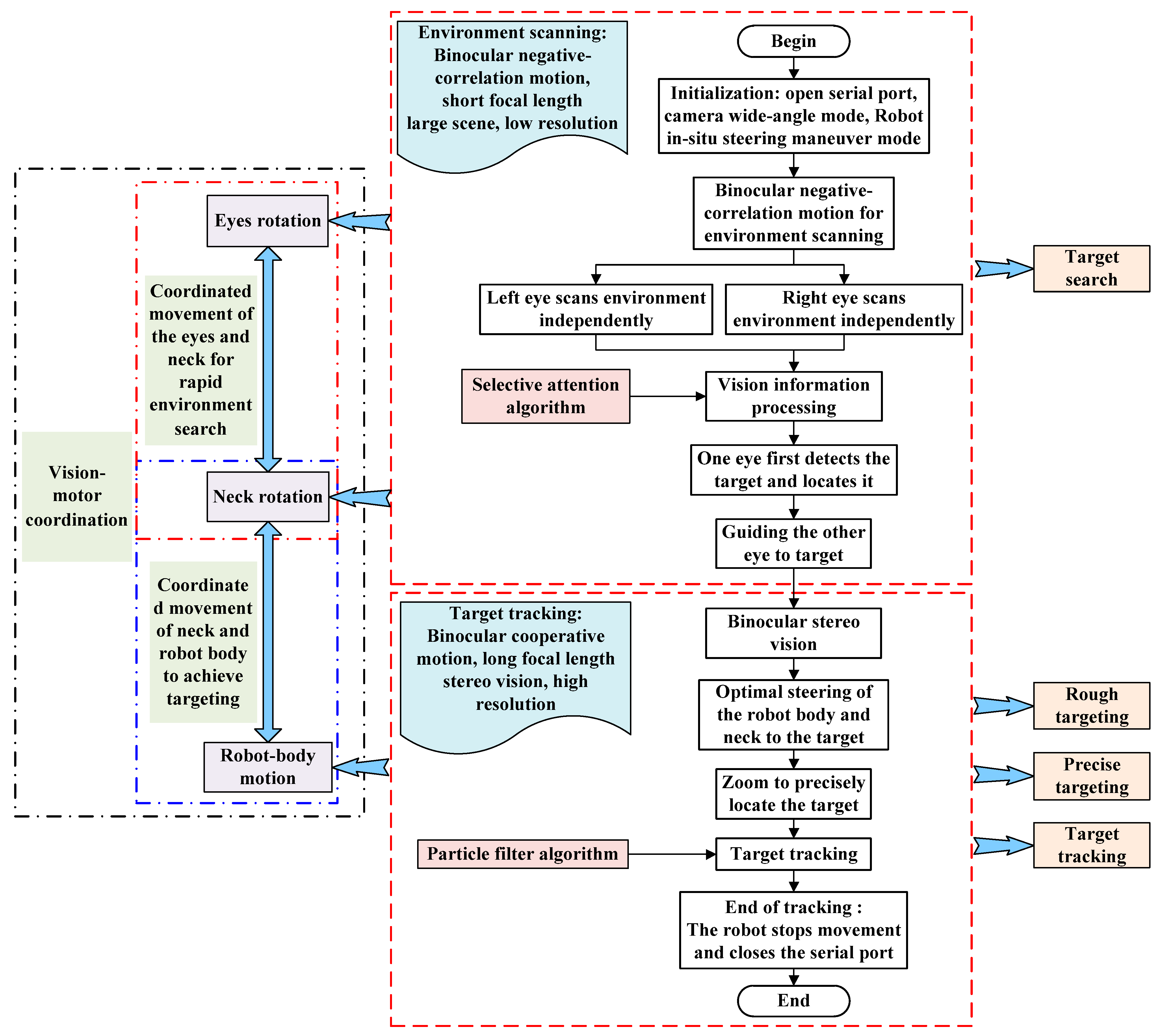
Chameleons are called “lions that crawl on the ground” because their vision systems play an important role in defending and hunting. Chameleons have peculiar eyes, which can move independently without interlocking to achieve panoramic observation, and they can move simultaneously to achieve binocular stereo vision. Inspired by this visual behavior of chameleons, this paper proposes an active-vision environment-perception strategy for WMRs based on a shifty-behavior mode, as shown in Figure 10. This method can reproduce the predation process of chameleons by executing a series of rhythmic movements to achieve the rapid searching, accurate positioning, and tracking of targets, and it can realize the coordinated motion of the robot’s body, neck, and eye in that process, i.e., vision–motor coordination [8].
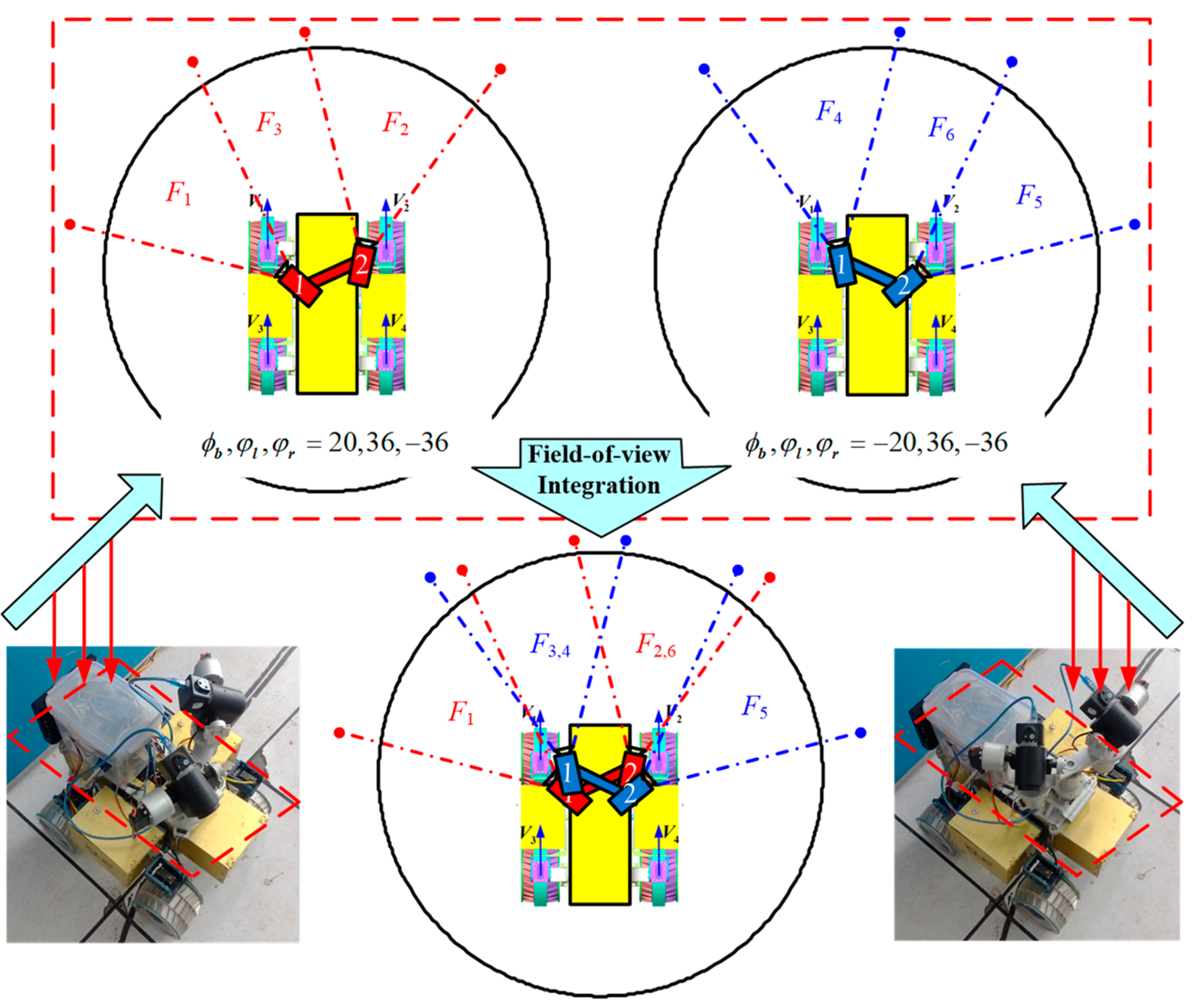
(1) Target search stage with chameleon-inspired binocular negative-correlation motion. The functional goal of this stage is to achieve a panoramic perception of the environment; therefore, to speed up the target search and reduce the burden of panoramic information processing, the search mode of the chameleon-inspired binocular negative-correlation motion is combined with the low-resolution mode of short focus. Given that the WMR proceeds in forward motion and the target behind the robot has been searched and tracked, the search range is set to the area of 160° in front of the robot, and the FOV of the two cameras in the wide-angle mode is 48°. In addition, to ensure the continuity and integrity of the search area, the overlapping FOV of the two cameras is 8°. According to the chameleon-inspired binocular negative-correlation-motion search model established above, the specific implementation process is shown in Figure 11. The FOV relationship of the robot is shown in Equation (11).
(2) Target recognition stage based on selective attention algorithm. In this paper, we used the selective attention algorithm proposed by Itti based on visual physiology and psychology [17], which uses a bottom-up data-driven model to obtain image saliency maps, including the extraction of multi-scale low-level features of images, the generation of multi-scale saliency maps, and attention focus acquisition and transferring.
Z 1 = { Z ( ϕ b , φ l , φ r , θ l , θ r , α , β , δ , r , s , ψ , Φ , i ) | ϕ b , φ l , φ r , θ l , θ r , α , β , δ , r , s , ψ , Φ , i = 20 ° , 36 ° , 36 ° , 30 ° , 30 ° , 48 ° , 36 , 8 , 1 , 160 , 1 } Z 2 = { Z ( ϕ b , φ l , φ r , θ l , θ r , α , β , δ , r , s , ψ , Φ , i ) | ϕ b , φ l , φ r , θ l , θ r , α , β , δ , r , s , ψ , Φ , i = 20 ° , 36 ° , 36 ° , 30 ° , 30 ° , 48 ° , 36 , 8 , 1 , 160 , 2 } Z 4 = { Z ( ϕ b , φ l , φ r , θ l , θ r , α , β , δ , r , s , ψ , Φ , i ) | ϕ b , φ l , φ r , θ l , θ r , α , β , δ , r , s , ψ , Φ , i = 20 ° , 36 ° , 36 ° , 30 ° , 30 ° , 48 ° , 36 , 8 , r , 160 , 1 } Z 5 = { Z ( ϕ b , φ l , φ r , θ l , θ r , α , β , δ , r , s , ψ , Φ , i ) | ϕ b , φ l , φ r , θ l , θ r , α , β , δ , r , s , ψ , Φ , i = 20 ° , 36 ° , 36 ° , 30 ° , 30 ° , 48 ° , 36 , 8 , r , 160 , 2 } Z 3 , 4 = Z 3 Z 4 Z 2 , 6 = Z 2 Z 6 Z 1 Z 3 , 4 Z 2 , 6 Z 5 = 160 °
(3) Target alignment stage. To achieve the accurate alignment of the robot to the target, a combination of the robot body and neck steering-alignment strategy and the zoom-accurate-alignment strategy is used. The rotation angles ω ,   ϕ b of the robot body and neck are γ , ϕ b I , where γ denotes the angle between the target and the longitudinal direction of the main robot body, and ϕ b I denotes the initial deviation angle of the neck (i.e., the angle between the neck and the longitudinal direction of the main robot body in the initial state), where 270 ° ω 270 ° , 180 ° γ 180 ° . Unlike the requirements of the target search stage, the target tracking stage is carried out to achieve precise positioning and tracking of the target, so binocular synchronous motion is used to achieve stereo vision combined with a long-focus high-resolution mode.
(4) Target tracking stage based on particle filtering algorithm. The particle filtering algorithm is used to approximate the posterior [43] probability distribution of random variables by using an importance sampling technique using the Monte Carlo simulation method [44]. Since the selective attention algorithm pays a lot of attention to the edge regions of specific objects and cannot select out the object centers, the target selection process is supervised in this paper by adopting a pre-learning approach for the objects to be tracked [45]. In addition, since the traditional particle filtering algorithm uses a fixed template, it is not very adaptable to changes in the shape, pose, and light of the tracked object. In order to improve the robustness of tracking, this paper improves the tracking accuracy by periodically updating the target model.

6. Experiments

To verify the effectiveness of the proposed chameleon-inspired active-vision environment-perception strategy based on a shifty-behavior mode for mobile robots, experiments were conducted based on a 4WD4WS mobile robot on rigid, flat ground and soft–rough sand, respectively.

6.1. Target Tracking Experiment of WMRs on Rigid, Flat Ground

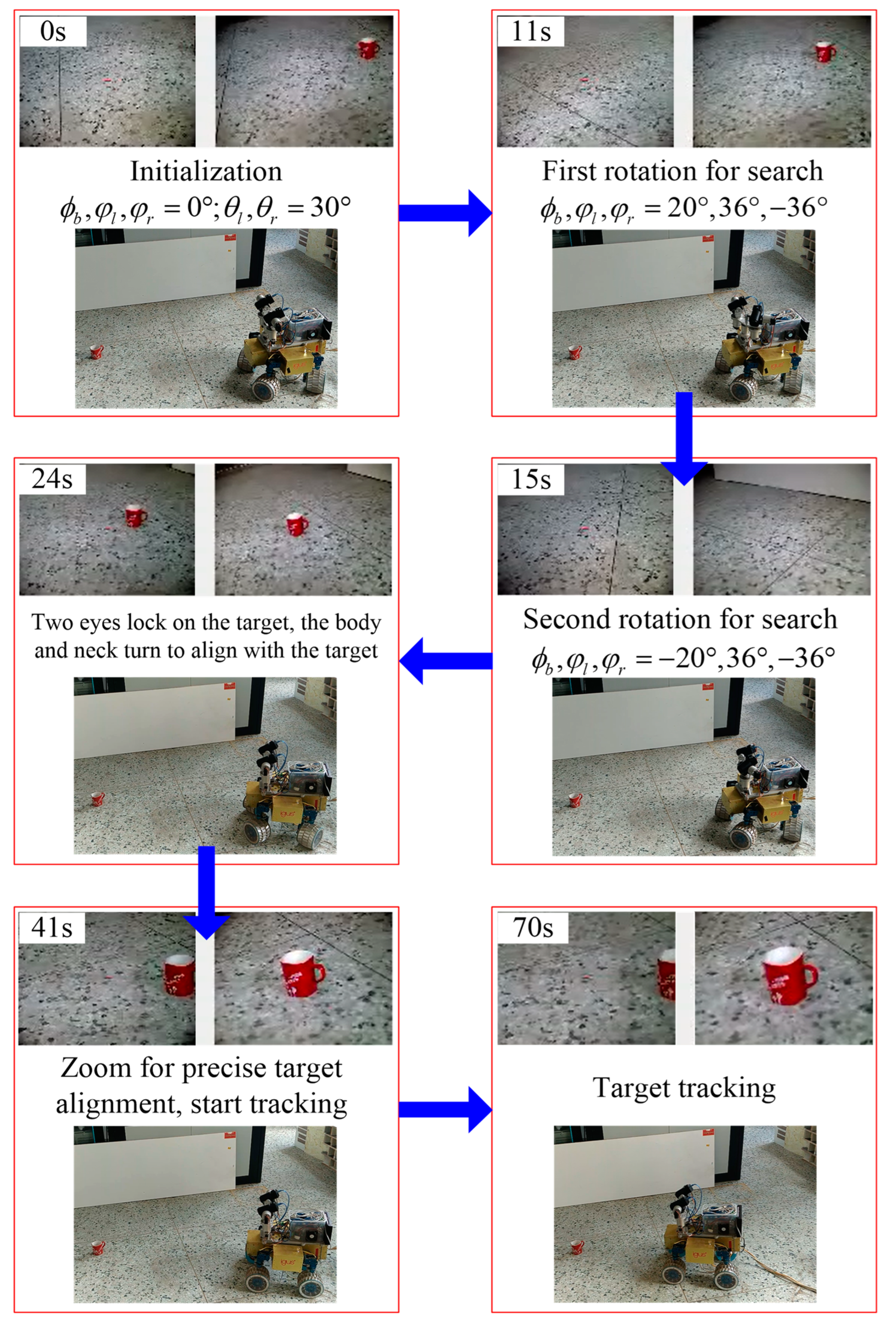
In this experiment, the robot was located indoors on rigid, flat ground to search and track a red target in front of it, as shown in Figure 12.
Target search stage: first, the robot was initialized with ϕ b , φ l , φ r , θ l , θ r = 0 , 0 , 0 , 30 , 30 , and the camera entered the short-focus mode. Then, at the 11th second and 15th second, respectively, the robot performed a rapid scan of the environment using the chameleon-inspired binocular negative-correlation-motion target search model.
ϕ b , φ l , φ r , θ l , θ r = 20 , 36 , 36 , 30 , 30 , q = 1 20 , 36 , 36 , 30 , 30 , q = 2
Subsequently, the four acquired images were compared and analyzed using the selective attention algorithm, and it was determined that when the neck and right camera were rotated ϕ b , φ r , θ r = 20 , 36 , 30 , respectively, the area located at the coordinate 248 , 77 of the image had the highest saliency. The horizontal and vertical orientation of the target was derived by the PTZ rotation equation as 27.1 ° , 28.0 ° . As shown in Figure 13a, we first used a histogram-based selective attention model to identify the targets [46], which uses histograms for image color statistics, first quantizing color images in RGB space and then performing a color-space smoothing operation, which is more suitable for mobile robot environment scenes. As shown in Figure 13b, we used superpixel segmentation [47] to improve the accuracy, which is more desirable in terms of execution speed, the compactness of the generated superpixels, and contour preservation.
Target alignment stage: first, in the 24th second, the robot body and vision system rotated by ϕ b , φ l , φ r , θ l , θ r = 0 , 0 , 0 , 28.0 , 28.0 ,   ω = 27.1 ° , respectively, aligning with the target, and the cameras moved together to realize stereo vision. Then, in the 41st second, the camera zoomed and entered the long-focus mode to obtain high-resolution pictures of the target to achieve precise target alignment.
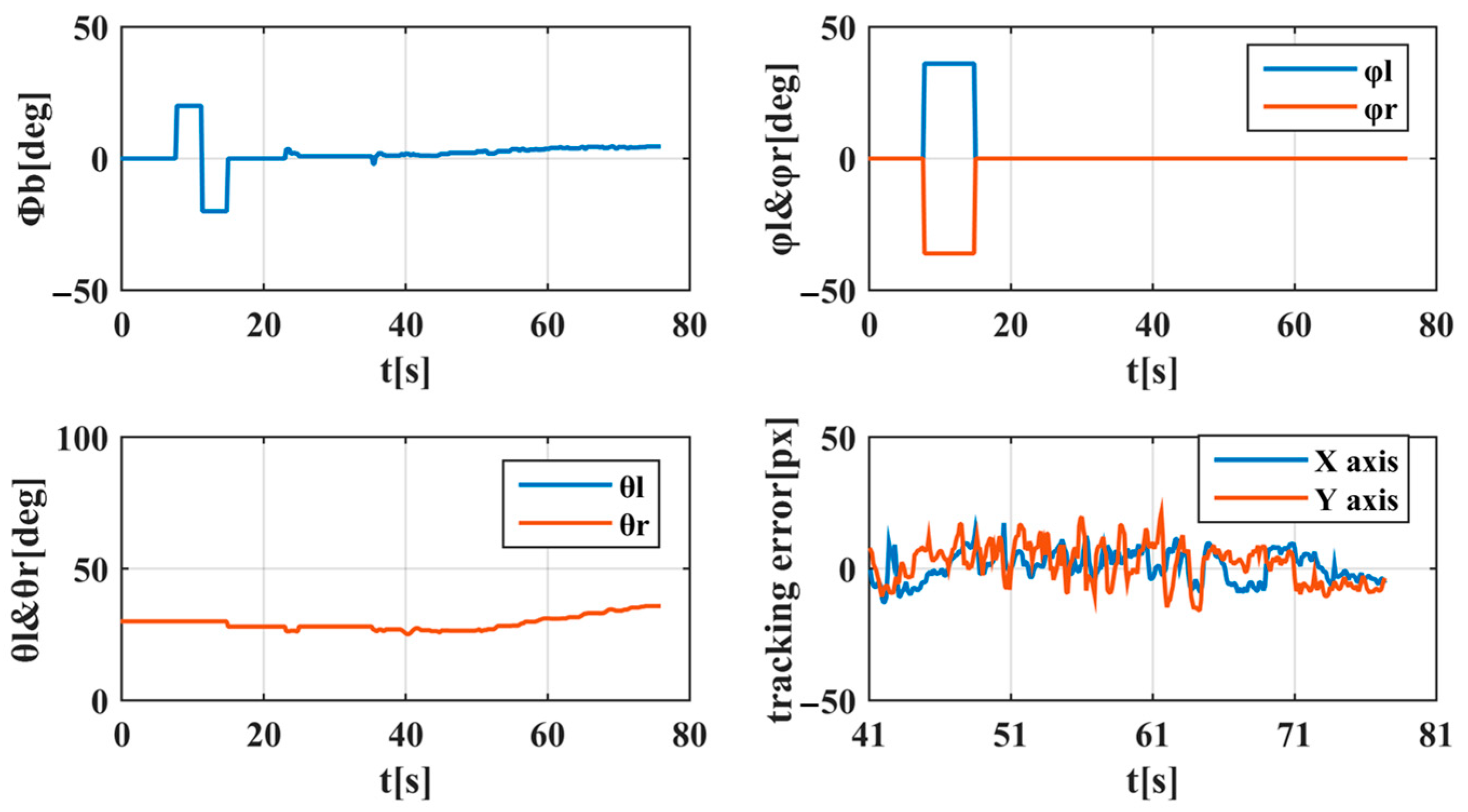
Target tracking stage: starting from the 41st second, the robot started to track the target. The experimentally collected rotation angles of each axis of the vision system and the target tracking error are shown in Figure 14. The tracking error curve showed that although the tracking error fluctuated due to the vibration problem of the robot itself, it always fluctuated around the 0 axis and was basically between plus and minus 15 pixels, indicating that the target tracking was achieved.

6.2. Target Tracking Experiment of WMRs on Soft–Rough Sand

In this experiment, the robot was located on soft–rough sand to search and track a red target in front of it, as shown in Figure 15.
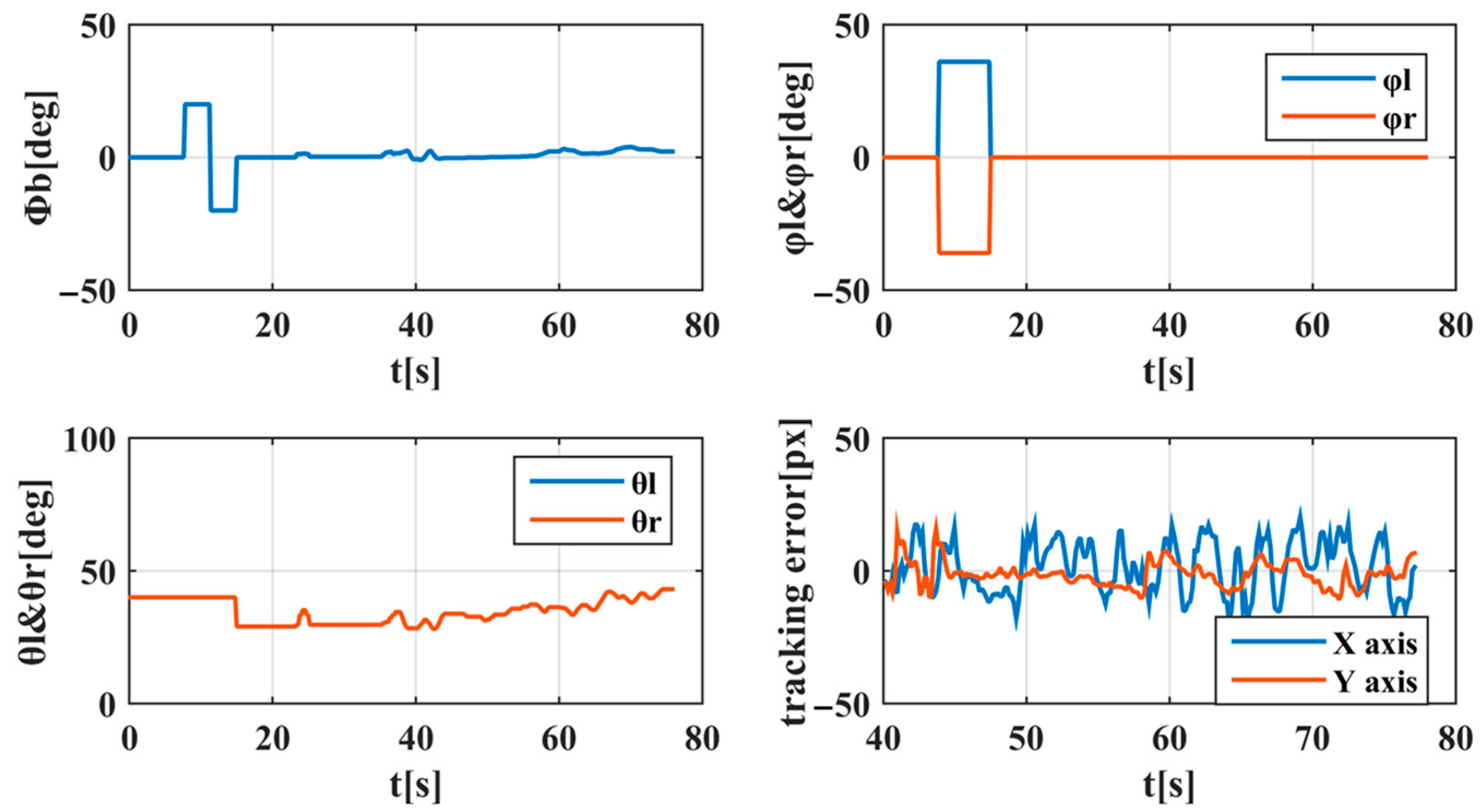
Target search stage: first, the robot was initialized with ϕ b , φ l , φ r , θ l , θ r = 0 , 0 , 0 , 40 , 40 , and the camera entered the short-focus mode. Then, at the 11th second and 15th second, the robot performed a rapid scan of the environment using the chameleon-inspired binocular negative-correlation-motion target search model.
ϕ b , φ l , φ r , θ l , θ r = 20 , 36 , 36 , 40 , 40 , q = 1 20 , 36 , 36 , 40 , 40 , q = 2
Then, the four acquired images were compared and analyzed using the selective attention algorithm, and it was determined that when the neck and right camera were rotated by ϕ b , φ r , θ r = 20 , 36 , 40 , respectively, the area located at the coordinate 248 , 49 of the image had the highest saliency. The horizontal and vertical orientation of the target was derived by the PTZ rotation equation as 28.6 ° , 29.7 . The image processing during the target search phase is shown in Figure 16.
Target alignment stage: first, in the 23rd second, the robot body and vision system rotated by ϕ b , φ l , φ r , θ l , θ r = 0 , 0 , 0 , 29.7 , 29.7 ,   ω = 28.6 ° , respectively, aligning with the target, and the cameras moved together to realize stereo vision. Then, in the 40th second, the camera zoomed into the long-focus mode to obtain high-resolution pictures of the target to achieve precise target alignment.
Target tracking stage: starting from the 40th second, the robot started to track the target. The experimentally collected rotation angles of each axis of the vision system and the target tracking error are shown in Figure 17. The tracking error curve showed that although the tracking error fluctuated due to vibration problems with the robot itself, it always fluctuated around the 0 axis and was basically between plus and minus 15 pixels, indicating that it could achieve the tracking of the target.
The experiments showed that this chameleon-inspired active-vision environment-perception strategy based on a shifty-behavior mode for mobile robots could achieve the rapid search and tracking of the target, and in this process, the coordinated movement of various parts could realize a sequence of actions being executed rhythmically, which achieved the reproduction of the visual behavior of chameleons in the vision system of the mobile robot with satisfactory results.

7. Conclusions

In this paper, the reproduction of the visual behavior of chameleons in the vision system of mobile robots was investigated with the following main results:
(1) The chameleon-inspired binocular negative-correlation-motion search mode significantly improved the search efficiency, range, flexibility, and image processing volume compared with the traditional binocular synchronous-motion search mode.
(2) The shifty-behavior mode binocular vision system had a better extension of the measurement range and a better adaptivity of the measurement accuracy compared with the traditional binocular vision system. In the target search stage, the wide-angle camera mode (with a large FOV) and the binocular negative-correlation-motion mode (with a large binocular merging FOV) were used for the rapid and large-range perception of the environment. In the target tracking stage, the long-focus camera mode (with a high measurement accuracy) and the binocular synchronous-motion mode (with a large binocular overlapping FOV) were used to achieve stereo vision for accurate target measurement and tracking.
(3) The effectiveness of the proposed chameleon-inspired active-vision environment perception model based on a shifty-behavior mode for mobile robots was verified through experiments with satisfactory results, which could realize its vision–motor coordination.

Author Contributions

Conceptualization, Y.X. and L.W.; methodology, Y.X.; software, Y.X.; validation, C.L. and Y.X.; formal analysis, H.C. and X.Y.; investigation, Y.S. and X.Y.; resources, Y.X. and L.W.; data curation, Y.X. and L.F.; writing—original draft preparation, Y.X. and L.F.; writing—review and editing, L.W.; visualization, H.C. and Y.S.; supervision, C.L. and L.W.; project administration, Y.X.; funding acquisition, Y.X and L.W. All authors have read and agreed to the published version of the manuscript.

Funding

This research was funded by the National Natural Science Foundation of China (52275264), the Scientific Research Foundation of Education Department of Liaoning Province (LJKQZ20222446), and the Doctoral Research Initiation Foundation of Shenyang Agricultural University(2017500065).

Institutional Review Board Statement

Not applicable.

Informed Consent Statement

Not applicable.

Data Availability Statement

Data sharing not applicable. No new data were created or analyzed in this study. Data sharing is not applicable to this article.

Acknowledgments

The authors would like to thank Xu He for his helpful comments and suggestions.

Conflicts of Interest

The authors declare no conflict of interest.

References

  1. Zhang, H.; Lee, S. Robot Bionic Vision Technologies: A Review. Appl. Sci. 2022, 12, 7970. [Google Scholar] [CrossRef]
  2. Dominguez-Morales, M.J.; Jimenez-Fernandez, A.; Jimenez-Moreno, G.; Conde, C.; Cabello, E.; Linares-Barranco, A. Bio-Inspired Stereo Vision Calibration for Dynamic Vision Sensors. IEEE Access 2019, 7, 138415–138425. [Google Scholar] [CrossRef]
  3. Corke, P. Robotics, Vision and Control; Springer Tracts in Advanced Robotics; Springer International Publishing: Cham, Switzerland, 2017; Volume 118, ISBN 978-3-319-54412-0. [Google Scholar]
  4. Bajcsy, R. Active Perception vs. Passive Perception. In Proceedings of the IEEE Workshop on Computer Vision, Bellaire, MI, USA, 13–16 October 1985; pp. 55–62. [Google Scholar]
  5. Bajcsy, R.; Aloimonos, Y.; Tsotsos, J.K. Revisiting Active Perception. Auton Robot 2018, 42, 177–196. [Google Scholar] [CrossRef]
  6. Tsotsos, J.K. A Computational Perspective on Visual Attention; MIT Press: Cambridge, MA, USA, 2021. [Google Scholar]
  7. Lev-Ari, T.; Lustig, A.; Ketter-Katz, H.; Baydach, Y.; Katzir, G. Avoidance of a Moving Threat in the Common Chameleon (Chamaeleo chamaeleon): Rapid Tracking by Body Motion and Eye Use. J. Comp. Physiol. A 2016, 202, 567–576. [Google Scholar] [CrossRef]
  8. Ketter-Katz, H.; Lev-Ari, T.; Katzir, G. Vision in Chameleons—A Model for Non-Mammalian Vertebrates. Semin. Cell Dev. Biol. 2020, 106, 94–105. [Google Scholar] [CrossRef] [PubMed]
  9. Billington, J.; Webster, R.J.; Sherratt, T.N.; Wilkie, R.M.; Hassall, C. The (Under)Use of Eye-Tracking in Evolutionary Ecology. Trends Ecol. Evol. 2020, 35, 495–502. [Google Scholar] [CrossRef] [PubMed]
  10. Herrel, A.; Meyers, J.J.; Aerts, P.; Nishikawa, K.C. The Mechanics of Prey Prehension in Chameleons. J. Exp. Biol. 2000, 203, 3255–3263. [Google Scholar] [CrossRef] [PubMed]
  11. Ott, M.; Schaeffel, F. A Negatively Powered Lens in the Chameleon. Nature 1995, 373, 692–694. [Google Scholar] [CrossRef]
  12. Ott, M.; Schaeffel, F.; Kirmse, W. Binocular Vision and Accommodation in Prey-Catching Chameleons. J. Comp. Physiol. A Sens. Neural Behav. Physiol. 1998, 182, 319–330. [Google Scholar] [CrossRef]
  13. Ott, M. Chameleons Have Independent Eye Movements but Synchronise Both Eyes during Saccadic Prey Tracking. Exp. Brain Res. 2001, 139, 173–179. [Google Scholar] [CrossRef] [PubMed]
  14. Avni, O.; Borrelli, F.; Katzir, G.; Rivlin, E.; Rotstein, H. Scanning and Tracking with Independent Cameras—A Biologically Motivated Approach Based on Model Predictive Control. Auton Robot 2008, 24, 285–302. [Google Scholar] [CrossRef]
  15. Avni, O.; Borrelli, F.; Katzir, G.; Rivlin, E.; Rotstein, H. Using Dynamic Optimization for Reproducing the Chameleon Visual System. In Proceedings of the 45th IEEE Conference on Decision and Control, San Diego, CA, USA, 13–15 December 2006; IEEE: Piscataway, NJ, USA, 2006; pp. 1770–1775. [Google Scholar]
  16. Prasad, R.; Vinothini, G.; Kumar, G.L.; Paul, S.; Geetha, S.; Surya Prabha, U.S. Chameleon Eye Motion Thruster for Missile System with Genetic Ontology Controller and Uncommon Transmission Antenna. In Proceedings of the 2015 SAI Intelligent Systems Conference (IntelliSys), London, UK, 10–11 November 2015; IEEE: Piscataway, NJ, USA, 2015; pp. 571–575. [Google Scholar]
  17. Xu, H.; Xu, Y.; Fu, H.; Xu, Y.; Gao, X.Z.; Alipour, K. Coordinated Movement of Biomimetic Dual PTZ Visual System and Wheeled Mobile Robot. Ind. Robot. Int. J. 2014, 41, 557–566. [Google Scholar] [CrossRef]
  18. Zhao, L.; Kong, L.; Qiao, X.; Zhou, Y. System Calibration and Error Rectification of Binocular Active Visual Platform for Parallel Mechanism. In Proceedings of the Intelligent Robotics and Applications: First International Conference, ICIRA 2008, Wuhan, China, 15–17 October 2008; Proceedings, Part I 1. Springer: Berlin/Heidelberg, Germany, 2008; pp. 734–743. [Google Scholar]
  19. Zhao, L.; Kong, L.; Wang, Y. Error Analysis of Binocular Active Hand-Eye Visual System on Parallel Mechanisms. In Proceedings of the 2008 International Conference on Information and Automation, Changsha, China, 20–23 June 2008; IEEE: Piscataway, NJ, USA, 2008; pp. 95–100. [Google Scholar]
  20. Zhou, J.; Wan, D.; Wu, Y. The Chameleon-Like Vision System. IEEE Signal Process. Mag. 2010, 27, 91–101. [Google Scholar] [CrossRef]
  21. Tsai, J.; Wang, C.-W.; Chang, C.-C.; Hu, K.-C.; Wei, T.-H. A Chameleon-like Two-Eyed Visual Surveillance System. In Proceedings of the 2014 International Conference on Machine Learning and Cybernetics, Lanzhou, China, 13–16 July 2014; IEEE: Piscataway, NJ, USA, 2014; pp. 734–740. [Google Scholar]
  22. Chen, R.; Chen, J.-Q.; Sun, Y.; Wu, L.; Guo, J.-L. A Chameleon Tongue Inspired Shooting Manipulator With Vision-Based Localization and Preying. IEEE Robot. Autom. Lett. 2020, 5, 4923–4930. [Google Scholar] [CrossRef]
  23. Liu, Y.; Zhu, D.; Peng, J.; Wang, X.; Wang, L.; Chen, L.; Li, J.; Zhang, X. Robust Active Visual SLAM System Based on Bionic Eyes. In Proceedings of the 2019 IEEE International Conference on Cyborg and Bionic Systems (CBS), Munich, Germany, 18–20 September 2019; IEEE: Piscataway, NJ, USA, 2019; pp. 340–345. [Google Scholar]
  24. Li, J.; Zhang, X. The Performance Evaluation of a Novel Methodology of Fixational Eye Movements Detection. Int. J. Biosci. Biochem. Bioinform. 2013, 3, 262–266. [Google Scholar] [CrossRef]
  25. Gu, Y.; Sato, M.; Zhang, X. A Binocular Camera System for Wide Area Surveillance. Eizo Joho Media Gakkaishi 2009, 63, 1828–1837. [Google Scholar] [CrossRef]
  26. Wang, Q.; Zou, W.; Xu, D.; Zhu, Z. Motion Control in Saccade and Smooth Pursuit for Bionic Eye Based on Three-Dimensional Coordinates. J. Bionic. Eng. 2017, 14, 336–347. [Google Scholar] [CrossRef]
  27. Wang, Q.; Zou, W.; Xu, D. 3D Perception of Biomimetic Eye Based on Motion Vision and Stereo Vision. Robot 2015, 37, 760–768. [Google Scholar] [CrossRef]
  28. Wang, Q.; Yin, Y.; Zou, W.; Xu, D. Measurement Error Analysis of Binocular Stereo Vision: Effective Guidelines for Bionic Eyes. IET Sci. Meas. Technol. 2017, 11, 829–838. [Google Scholar] [CrossRef]
  29. Fan, D.; Liu, Y.; Chen, X.; Meng, F.; Liu, X.; Ullah, Z.; Cheng, W.; Liu, Y.; Huang, Q. Eye Gaze Based 3D Triangulation for Robotic Bionic Eyes. Sensors 2020, 20, 5271. [Google Scholar] [CrossRef]
  30. Chen, X.; Wang, C.; Zhang, W.; Lan, K.; Huang, Q. An Integrated Two-Pose Calibration Method for Estimating Head-Eye Parameters of a Robotic Bionic Eye. IEEE Trans. Instrum. Meas. 2020, 69, 1664–1672. [Google Scholar] [CrossRef]
  31. Chen, J.; Chen, Y.; Zhao, H.; Ma, T. Development of Neural-network-based Stereo Bionic Compound Eyes with Fiber Bundles. Concurr. Comput. 2022, 35, e7464. [Google Scholar] [CrossRef]
  32. Chen, X.; Wang, C.; Zhang, T.; Hua, C.; Fu, S.; Huang, Q. Hybrid Image Stabilization of Robotic Bionic Eyes. In Proceedings of the 2018 IEEE International Conference on Robotics and Biomimetics (ROBIO), Kuala Lumpur, Malaysia, 12–15 December 2018; IEEE: Piscataway, NJ, USA, 2018; pp. 808–813. [Google Scholar]
  33. Zhao, W.; Liu, H.; Lewis, F.L.; Wang, X. Data-Driven Optimal Formation Control for Quadrotor Team With Unknown Dynamics. IEEE Trans. Cybern. 2022, 52, 7889–7898. [Google Scholar] [CrossRef]
  34. Tu Vu, V.; Pham, T.L.; Dao, P.N. Disturbance Observer-Based Adaptive Reinforcement Learning for Perturbed Uncertain Surface Vessels. ISA Trans. 2022, 130, 277–292. [Google Scholar] [CrossRef]
  35. Zhao, W.; Liu, H.; Lewis, F.L. Data-Driven Fault-Tolerant Control for Attitude Synchronization of Nonlinear Quadrotors. IEEE Trans. Automat. Contr. 2021, 66, 5584–5591. [Google Scholar] [CrossRef]
  36. Dao, P.N.; Liu, Y. Adaptive Reinforcement Learning in Control Design for Cooperating Manipulator Systems. Asian J. Control 2022, 24, 1088–1103. [Google Scholar] [CrossRef]
  37. Soechting, J.F.; Flanders, M. Moving in Three-Dimensional Space: Frames of Reference, Vectors, and Coordinate Systems. Annu. Rev. Neurosci. 1992, 15, 167–191. [Google Scholar] [CrossRef]
  38. Li, Y.; Shum, H.-Y.; Tang, C.-K.; Szeliski, R. Stereo Reconstruction from Multiperspective Panoramas. IEEE Trans. Pattern Anal. Mach. Intell. 2004, 26, 45–62. [Google Scholar] [CrossRef]
  39. Hamdia, K.M.; Zhuang, X.; Rabczuk, T. An Efficient Optimization Approach for Designing Machine Learning Models Based on Genetic Algorithm. Neural Comput Applic 2021, 33, 1923–1933. [Google Scholar] [CrossRef]
  40. Dutta, A.; Mondal, A.; Dey, N.; Sen, S.; Moraru, L.; Hassanien, A.E. Vision Tracking: A Survey of the State-of-the-Art. SN Comput. Sci. 2020, 1, 57. [Google Scholar] [CrossRef]
  41. Grosfeld-Nir, A.; Ronen, B.; Kozlovsky, N. The Pareto Managerial Principle: When Does It Apply? Int. J. Prod. Res. 2007, 45, 2317–2325. [Google Scholar] [CrossRef]
  42. Zhang, X. New Developments for Net-Effect Plots. Wiley Interdiscip. Rev. Comput. Stat. 2013, 5, 105–113. [Google Scholar] [CrossRef]
  43. Ding, J.; Chen, J.; Lin, J.; Wan, L. Particle Filtering Based Parameter Estimation for Systems with Output-Error Type Model Structures. J. Frankl. Inst. 2019, 356, 5521–5540. [Google Scholar] [CrossRef]
  44. Arend, M.G.; Schäfer, T. Statistical Power in Two-Level Models: A Tutorial Based on Monte Carlo Simulation. Psychol. Methods 2019, 24, 1. [Google Scholar] [CrossRef] [PubMed]
  45. Wang, L.; Liu, T.; Wang, G.; Chan, K.L.; Yang, Q. Video Tracking Using Learned Hierarchical Features. IEEE Trans. Image Process. 2015, 24, 1424–1435. [Google Scholar] [CrossRef] [PubMed]
  46. Cheng, M.-M.; Mitra, N.J.; Huang, X.; Torr, P.H.S.; Hu, S.-M. Global Contrast Based Salient Region Detection. IEEE Trans. Pattern Anal. Mach. Intell. 2015, 37, 569–582. [Google Scholar] [CrossRef]
  47. Achanta, R.; Shaji, A.; Smith, K.; Lucchi, A.; Fua, P.; Süsstrunk, S. SLIC Superpixels Compared to State-of-the-Art Superpixel Methods. IEEE Trans. Pattern Anal. Mach. Intell. 2012, 34, 2274–2282. [Google Scholar] [CrossRef] [PubMed]
Figure 1. Independent eye movements in a chameleon.
Applsci 13 06069 g001
Figure 2. Construction of the chameleon-inspired binocular vision system for WMRs.
Applsci 13 06069 g002
Figure 3. Coordinate systems of the vision system for WMRs: (a) PTZ coordinate system; (b) image coordinate system.
Applsci 13 06069 g003
Figure 4. FOV model and imaging model in binocular synchronous motion mode: (a) horizontal field-of-view model of binocular vision system; (b) imaging model of binocular vision system.
Applsci 13 06069 g004
Figure 5. FOV model and imaging model in binocular negative-correlation-motion mode: (a) horizontal field-of-view model of binocular vision system; (b) imaging model of binocular vision system.
Applsci 13 06069 g005
Figure 6. Relationship between the binocular horizontal overlapping FOV and parameters in binocular negative-correlation-motion mode: (a) relationship surface of r12 with a, f; (b) relationship surface of r12 with α, l; (c) main effect diagram of a, f, α, l on r12; (d) Pareto diagram of a, f, α, l on r12.
Applsci 13 06069 g006
Figure 7. Relationship between the binocular horizontal merging FOV and parameters in binocular negative-correlation-motion mode: (a) relationship surface of r0 with a, f; (b) relationship surface of r0 with α, l; (c) main effect diagram of a, f, α, l on r0; (d) Pareto diagram of a, f, α, l on r0.
Applsci 13 06069 g007aApplsci 13 06069 g007b
Figure 8. Relationship between the X resolution of the vision system and parameters in binocular negative-correlation-motion mode: (a) relationship surface of ΔX with a, f, l; (b) relationship surface of ΔX with x, z, Δw; (c) main effect diagram of a, f, l, x, z, Δw on ΔX; (d) Pareto diagram of a, f, l, x, z, Δw on ΔX.
Applsci 13 06069 g008aApplsci 13 06069 g008b
Figure 9. Relationship between the Z resolution of the vision system and parameters in binocular negative-correlation-motion mode: (a) relationship surface of ΔZ with a, f, l; (b) relationship surface of ΔZ with x, z, Δw; (c) main effect diagram of a, f, l, x, z, Δw on ΔZ; (d) Pareto diagram of a, f, l, x, z, Δw on ΔZ.
Applsci 13 06069 g009
Figure 10. Environment perception strategy in chameleon-inspired active vision based on shifty-behavior mode for WMRs.
Applsci 13 06069 g010
Figure 11. Search process in chameleon-inspired binocular negative-correlation motion for WMRs.
Applsci 13 06069 g011
Figure 12. Target tracking process of WMRs on rigid, flat ground.
Applsci 13 06069 g012
Figure 13. Image processing during target search stage: (a) saliency map; (b) superpixel segmentation process.
Applsci 13 06069 g013
Figure 14. Tracking data curve of WMRs on rigid, flat ground.
Applsci 13 06069 g014
Figure 15. Target tracking process of WMRs on soft–rough sand.
Applsci 13 06069 g015
Figure 16. Image processing during target search stage: (a) saliency map; (b) superpixel segmentation process.
Applsci 13 06069 g016
Figure 17. Tracking data curve of WMRs on soft–rough sand.
Applsci 13 06069 g017
Table 1. Parameters of lens and CMOS.
SensorsParametersValues
LensModelSSL06036M
Size of target surface 1/3″
Focal length6.0–36.0 mm
Minimum focus distance1.3 m
Back focus distance 12.50 mm
CMOSModelSuntime-200
Pixel size3.2 μm × 3.2 μm
Scanning typeLine-by-line scanning
Resolution320 × 240, 640 × 480, 1280 × 1024
Transmission rate30 fps: 320 × 240, 640 × 480
Table 2. Parameters of the binocular visual system of WMRs.
ParametersDescriptionsRange (mm)ParametersDescriptionsRange (mm)
a Length of CMOS target surface 3.6 , 12.7 θ 1 , θ 2 Monocular horizontal FOV 9.3 ° , 50.9 °
f Focal length 6 , 36 θ 12 Binocular overlapping horizontal FOVN/A
l Distance between two eyes 90 , 360 θ 0 Binocular merging horizontal FOVN/A
d Object distanceN/A r 1 , r 2 Radius of the inner tangent circle of the monocular horizontal FOVN/A
d 12 Distance from the object to the vertex of the binocular horizontal overlapping FOVN/A r 12 Radius of the inner tangent circle of the binocular horizontal overlapping FOVN/A
d 0 Distance from the object to the vertex of the binocular horizontal merging FOVN/A r 0 Radius of the inner tangent circle of the binocular horizontal merging FOVN/A
A Length of target objectN/A Δ w Size of CMOS image element 0.002 , 0.01
P x , z Position of the target object in the effective horizontal FOVN/A
Disclaimer/Publisher’s Note: The statements, opinions and data contained in all publications are solely those of the individual author(s) and contributor(s) and not of MDPI and/or the editor(s). MDPI and/or the editor(s) disclaim responsibility for any injury to people or property resulting from any ideas, methods, instructions or products referred to in the content.