Abstract
A feasibility study is presented exploring the possibility of using thermoelectric devices for the thermal control of CubeSat on-board electronics. A simple thermoelectric architecture is devised and an empirical model for how such a system would perform is constructed, using the performance data of a commercially available thermoelectric module. This is used to calculate the temperature to which the system could cool a computer chip, as a function of thermal resistance and heat rejection. As a baseline scenario, the temperature of the system without the thermoelectric device is compared and the benefit, or otherwise, of using a thermoelectric module is calculated. Analysis shows that in some circumstances introducing a thermoelectric device would actually increase the temperature of the electronics being cooled. This is most common when the quantity of heat being removed, or the thermal resistance of the system, is high. Nevertheless, thermoelectric cooling is beneficial for a range of conditions, such as for cooling the computer chip below ambient temperature, however a good quality radiator is required. This constraint could undermine the thermoelectric device’s potential benefit in many cases, due to the need for an unrealistically large radiator.
1. Introduction
Thermal management is becoming a critical issue for advanced low-Earth orbit (LEO) small satellite (SmallSat) missions. However, it is one whose significance is often overlooked. This is despite the number of launched SmallSats rising considerably to >1000 per year—an order of magnitude increase over the past decade and a trend that is predicted to grow [1].
Future advanced SmallSat services, such as Earth Observation, Space Situational Awareness and Next Generation Satellite Communications (NextGenSatCom), will require increasing onboard computational power, something that will generate more heat, which must be managed [2].
A CubeSat is a class of SmallSat, built in cubic units of approximately 0.1 m × 0.1 m × 0.1 m, with each cube weighing approximately 1 kg. CubeSats are typically in the 1 U to 6 U range and are often assembled using off-the-shelf componentry. CubeSats often rely on the (emissivity/absorptivity) properties of their external surfaces, in combination with orbit attitude, to ensure that on-board electronics and/or other heat-sensitive components remain within the manufacturer’s recommended temperature range—the maximum operating temperature being ordinarily between 85 °C and 120 °C [3,4]. The reliability of space electronics is critical and this is closely related to operating temperature. Studies have shown that reliability decreases by 50% for every 10 °C increase in operating temperature [5]. Mithal [6] found that for every 1 °C decrease in the temperature of electronic chips, the failure rate of the electronic chips would decrease by about 4%. Similarly, even if the electronic chips are not damaged at elevated temperature, their life span is shortened significantly [7].
Deployable radiators can be used to dissipate larger amounts of heat, however, their use can add significant additional complexity and a greater risk of mission failure, should they unsuccessfully deploy. Likewise, their surface area is often limited [2].
It is possible to aid the performance of standard, body-mounted radiators by minimizing the thermal resistance between the heat-generating electronics and the radiators. This can be achieved by a number of methods, usually defined as either passive or active systems.
Passive systems are often the preferred solution since they offer advantages in terms of simplicity, cost, mass, volume, as well as requiring no electrical power. Heat pipes are the most common heat transfer device used on SmallSats [2]. They consist of a metal pipe that holds a liquid under pressure and a wick. When one end of the pipe is heated the liquid at that end vaporizes and moves to the cooler end where it condenses and is transported back to the other end by wicking, for the cycle to repeat. This method is effective, but its use of a liquid can lead to catastrophic failure if a leak occurs. The same issue is applicable to passive systems employing phase change materials for thermal management.
The major drawback for active systems is their added complexity and a reliance on input power for operation. They have however been shown to offer tight temperature control, to cool below ambient temperatures, and offer the potential for higher-performance cooling [2]. Ultimately, the choice of thermal management technology and whether to employ a passive or active system, is often a trade-off between performance benefits and the additional costs (time, risk, financial) associated with development.
Thermoelectric modules are one category of active thermal management device. They exploit the Peltier effect to create a heat flux at the junction of two different types of materials. A thermoelectric cooler is effectively a solid-state heat pump that rejects heat from one side of the module to the other, while consuming electrical energy. Thermoelectric modules have found a variety of applications terrestrially. Their solid-state nature—and lack of moving parts—makes them attractive for space applications, due to increased reliability, lifetime and reduced vibration. Unlike other active systems, they do not require fluid flow, such as in vapor-compression cycle refrigeration [8]. On the other hand, thermoelectric devices have a much lower coefficient of performance (COP) than competing active cooling technologies, which often stifles their uptake in applications [2], although they are used extensively for precise cooling of laser diodes [9].
Thermoelectric devices already have space heritage, having, for example, been used to cool CCD sensors on the Mars Curiosity Rover [10], and for thermal stabilization on the International Space Station and larger satellites [11]. They have not—to our knowledge—been previously used on CubeSats. Therefore this study is the first to assess the viability of using thermoelectric cooling for thermal management of on-board electronics on CubeSats.
2. Methodology
2.1. A CubeSat Thermoelectric Cooling System
For this assessment, a simple thermoelectric cooling architecture, which could be applied to a CubeSat payload, is considered. In the CubeSat, the thermoelectric module would be placed in contact with the electronics to be cooled. This might consist of a printed circuit board (PCB), containing a central processing unit (CPU), in direct contact with the module. During operation, the CPU would generate heat that is removed by the thermoelectric module, which would absorb heat at its cold (bottom) side. The heat rejected from the hot (top) side of the module would then be conducted to a radiator (for example, via copper thermal strap) to be rejected to deep space. In order that a broad assessment of feasibility could be carried out, the dimensions of the system were able to be discounted. Likewise for simplicity, the overall thermal resistance between the thermoelectric module and the radiator (i.e., the thermal strap and radiator) was combined into a single variable. As a baseline scenario, the performance of the system without the thermoelectric module was used for comparison.
2.2. Empircal Model of a Commercial Thermoelectric Module
The analysis is based on the manufacturer’s performance data for a commercial thermoelectric device (APHC-12706-S from European Thermodynamics Ltd., Kibworth, UK [12]) which is a 40 mm × 40 mm × 4 mm module. The module is of single stage geometry and is specifically designed for temperature cycling applications. It can provide a maximum temperature difference of 66 °C and is operational to a maximum hot-side temperature of 180 °C.
In order to calculate the module’s cold-side temperature as a function of the thermal resistance of the system, four empirical models were created. Module performance data was extracted from the data sheet [12]. The four models consist of linear fits for each of the supplied performance data sets for testing at 25 °C and 75 °C, and are shown in Figure 1. The fits calculate the total heat dissipated at the hot side of the module and the temperature difference (∆T) across the thermoelectric device, as a function of the heat pumped at the cold side, which was considered equivalent to the CPU power. The module data sheet provides constant-current performance data up to a maximum supplied voltage of 14.7 V. In this study we have imposed an upper bound on the on-board voltage of 12 V, based on what might be a realistic constraint on a CubeSat [13], meaning that module performance data for V > 12 V was ignored.
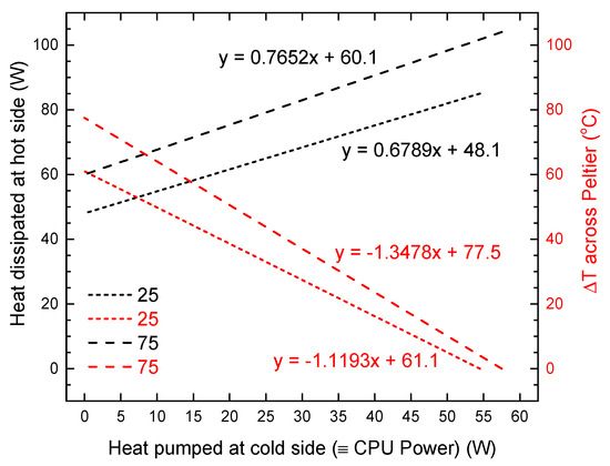
Figure 1.
Empirical models for the total heat dissipated at the hot side of the thermoelectric module (black lines) and the temperature difference (∆T) across the module (red lines), as a function of the heat pumped at the cold-side [12]. The legend shows the average operating temperature of the module when the performance testing was carried out, in °C.
2.3. Calculating CPU Temperature
For the baseline example with no thermoelectric module, the increase in temperature of the CPU under hypothetical operation is calculated by multiplying the emitted CPU power (in W) by the thermal resistance of the system (in °C/W). In the analysis, the CPU power was set and varied between 0 and 60 W, in 0.1 W steps. Likewise, the supposed thermal resistance was varied between 0 and 1.2 °C/W, in 0.01 °C/W steps. The CPU temperature was then calculated by adding this increase to the assumed initial temperature inside the payload, prior to the electronics becoming operational. The internal payload temperature would vary throughout orbit as a function of attitude, but for low-Earth orbit is typically in the range −20 °C to +70 °C [14]. In this study, this initial temperature was considered to be either 25 °C or 75 °C, since thermoelectric performance data was available for these temperatures. It was important that both cases were considered, since the module’s performance varied as a function of its average temperature.
For the thermoelectric-cooled comparison, the cold-side temperature of the thermoelectric module was considered equivalent to the CPU temperature from the baseline example. This cold-side temperature was calculated in two steps: First, a temperature was calculated by multiplying the total heat dissipated at the hot-side of the thermoelectric device according to the set thermal resistance of the system. Note that this total included both the emitted CPU power as before, as well as the additional Joule heat generated in the thermoelectric device. The total heat dissipated was found by reference to the appropriate empirical model (black line) in Figure 1. For example, if the initial temperature was 25 °C and 40 W was to be removed from the CPU, the total heat removed at the hot side was (approximately) 75 W, as indicated by the short-dashed line in Figure 1. Likewise, by referring to the appropriate ∆T empirical model in Figure 1 (red lines), the imposed temperature difference across the thermoelectric device was then identified and subtracted to give the cold-side temperature. Comparison of the cold-side temperature and the baseline case allowed the benefit, or detriment, enacted by the thermoelectric device to be calculated. MATLAB was used to carry out all combinations of calculations and steps used in the calculations are shown in Figure 2.
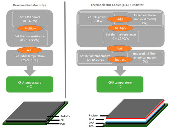
Figure 2.
Steps involved in the calculation of CPU temperature for the baseline case (radiator only) and in the case where a thermoelectric cooler is used. In each calculation the CPU power was set and varied between 0 and 60 W, in 0.1 W steps, the thermal resistance was set and varied between 0 and 1.2 °C/W, in 0.01 °C/W steps, and the initial temperature was set as either 25 °C or 75 °C. For thermoelectric cooling the impact of Joule heating and imposed temperature difference were incorporated using linear fits to the manufacturer’s empirical data from Figure 1. Diagrams at the bottom show the schematic structure of the simple thermoelectric module (TEM) cooling geometry and the baseline set-up.
2.4. Radiator Size
In a final step, an estimate of the radiator size that would enable a given thermal resistance was made. The radiator emissivity was set to 0.95 and the radiator was assumed to radiate to deep space, at a temperature of 3 K. The thermal resistance (R) was also calculated as a function of radiator temperature, according to [15]
where ε is emissivity, σ is the Stefan-Boltzmann constant, A is the area of the radiator, Trad is the radiator’s temperature and Tspace is the temperature of deep space—3 K.
3. Results and Discussion
3.1. Empirical Thermoelectric Performance Model
Figure 1 presents the empirical models for the total heat dissipated at the hot side of the thermoelectric module and the temperature difference (∆T) across the module, as a function of the heat pumped at the cold-side [12]. The legend shows the average operating temperature used when generating the experimental performance data, in °C. Figure 1 demonstrates that the ∆T produced by the thermoelectric module is a linear function of the power transferred through the thermal element, with negative slope. The heat dissipated at the hot side rises linearly with the heat absorbed at the cold side of the module. Comparing the module’s operation at 25 °C and 75 °C shows that a greater temperature difference is achievable at the higher operating temperature, however this requires greater heat removal from the cold side.
3.2. Benefits of the Thermoelectric Module
Figure 3a,b present plots of the system’s thermal resistance versus the heat pumped at the cold-side of the thermoelectric module, that is the heat removed from the warm object, such as a CPU, for example. Figure 3a presents data for the module’s performance extracted at 25 °C and Figure 3b shows the same analysis for 75 °C performance. A deeper discussion of what R corresponds to, in terms of the physical characteristics of the radiator, will be discussed later.
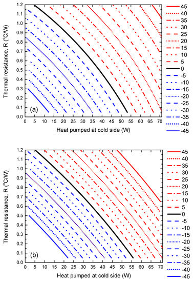
Figure 3.
The thermoelectric system’s thermal resistance versus the heat pumped at the cold-side of the thermoelectric module. The black line represents conditions i.e., required heat to be removed versus radiator thermal resistance, where a thermoelectric module in combination with a radiator would perform equally as well as the radiator alone. Blue lines indicate conditions where the thermoelectric module provides benefit, whereas red lines indicate conditions where the thermoelectric module is detrimental. The legend indicates (in °C) how much the benefit/detriment is. (a) Presents data for the module’s performance extracted at 25 °C and (b) shows the same analysis for 75 °C.
Lines on each of Figure 3a,b represent the benefit or detriment enacted by the addition of a thermoelectric module for cooling. The value assigned to each line (in the legend) represents this numerically (in °C), where positive (red) values show that the temperature at the cold-side of the module would be hotter than the equivalent scenario where no thermoelectric module is used and heat rejection occurs using just a radiator. Likewise, negative (blue) values indicate that the thermoelectric module cools to a temperature below that achieved with a radiator alone. As an example, the bold dashed line indicates that the thermoelectric device would cool a CPU to a temperature 5 °C below that for a radiator alone, when 35 W is removed from the cold side of the device (i.e., when the CPU power is 35 W) and the radiator has a thermal resistance of 0.45 °C/W.
The black line represents conditions i.e., required heat to be removed versus radiator thermal resistance, where a thermoelectric module in combination with a radiator would perform equally as well as the radiator alone. In this case, there is therefore no benefit in implementing a thermoelectric solution.
The red lines indicate conditions where introducing a thermoelectric system would actually increase the temperature of the CPU being cooled. This is most common in the top, right-hand side of Figure 3a,b, where the quantity of heat being removed is high, as is the thermal resistance of the system. This is somewhat counterintuitive initially, since one might expect that thermoelectrics would be of added benefit when the radiator performance is limited or when more heat is generated and requires removal. However, this is not the case, since to pump heat from the cold side, the thermoelectric device consumes electrical energy which generates extra I2R heat, adding to that which must be dissipated by the radiator at the module’s hot-side.
Nevertheless, thermoelectric cooling does make sense for a range of conditions, especially in the bottom, left-hand side of Figure 3a,b, when a good quality radiator is employed. In a limited number of cases, it is possible to cool the CPU to 45 °C below that which can be achieved with just a radiator.
This analysis indicates that careful consideration of the cooling requirements and the thermal resistance of the refrigeration system are crucial in advance of selecting an active thermoelectric-based cooling solution. The slight differences between Figure 3a,b show that it is important to also consider the working temperature(s) of the thermoelectric module and identify its performance accordingly.
3.3. Temperatures Achieved with Thermoelectric Cooling
In Figure 4a,b, the cold-side temperature that is produced by the thermoelectric module is presented, again as a function of the system’s thermal resistance.
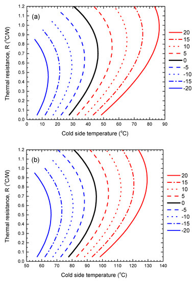
Figure 4.
Thermal resistance versus the cold-side temperature produced by the thermoelectric module. Black line represents the imposed cold-side temperature for the conditions where a thermoelectric module in combination with a radiator would perform equally as well as the radiator alone. Blue lines indicate the temperature when the thermoelectric system is beneficial, whereas red lines indicate the temperature when the thermoelectric module is detrimental. The legend indicates (in °C) how much the benefit/detriment is. (a) Presents data for the initial temperature of 25 °C and (b) shows the same analysis for 75 °C.
The black line represents the imposed cold-side temperature for the conditions where a thermoelectric module in combination with a radiator would perform equally as well as the radiator alone. Blue lines indicate the temperature when the thermoelectric system is beneficial, whereas red lines indicate the temperature when the thermoelectric module is detrimental. In Figure 4a temperatures are presented for the initial CubeSat temperature of 25 °C, whereas in Figure 4b the initial temperature was 75 °C.
For Figure 4a it is clear that for thermal resistance/heat removal conditions where thermoelectrics is of benefit, relatively low temperatures are enforced on the object being cooled. For example, for a thermal resistance of 0.6 °C/W (providing cooling of approximately 25 W and a ∆T of −10 °C, according to Figure 3a), the CPU would be cooled to a temperature of approximately 30 °C. While this is in the middle of the recommended operational temperature range for (CubeSat) electronics, Figure 4a also implies that without the thermoelectric module—and using just a radiator—the CPU temperature would be approximately 40 °C. This is also a comfortable operating temperature for the electronics. Therefore, in this case, while the thermoelectric system would provide additional cooling, it is unlikely to be worthwhile to implement.
The conclusion is however slightly different when the CubeSat has an initial temperature of 75 °C. In this case, since the electronics are already at a temperature at the upper end of the acceptable working range, thermoelectric cooling can be beneficial. For example, for a thermal resistance of 0.6 °C/W (and with cooling of approximately 14 W and a ∆T of −20 °C, according to Figure 3b), the CPU would be cooled to a temperature of approximately 66 °C. Without the thermoelectric system, the CPU would heat up to a temperature of 86 °C, which is unfavorable and therefore might justify the use of a thermoelectric module. It is likely to be in this type of scenario were thermoelectric cooling—capable of cooling below ambient temperature—is likely to be of benefit. However, for the majority of CubeSat orbits, the initial CubeSat temperature is unlikely to reach as high as 75 °C, used in this part of the study. Therefore the use of thermoelectric cooling for CubeSats may only be applicable in a small number of use cases. That said, there are certainly other space-based environments where the ability to cool below ambient would be of benefit, e.g., on the Moon or Mars, during the day time. Indeed, thermoelectric cooling has already been demonstrated for such scenarios in the past, e.g., for the Mars Curiosity Rover.
One scenario where thermoelectric cooling could be used on CubeSats, is for very precise and accurate temperature control of temperature-sensitive components, e.g., sensors and detectors. This is a common requirement on-board satellites, particularly for sensors with cryo-temperature dependencies in order to provide stable measurements. The fact that thermoelectric coolers can refrigerate to sub-ambient temperatures makes them an option for such use cases. It is important to note however that they should be considered in comparison to other active cooling solutions.
3.4. Radiator Size
This assessment was carried out for a single thermoelectric module to manage a heat load of up to approximately 50 W using a module that is 40 mm × 40 mm × 4 mm. However, the findings are expected to be scalable, given the scalability of thermoelectric modules, both to larger and smaller sizes, e.g., two modules could be used to cool a 100 W heat load and so on. The caveat is that the size of the radiator would need to scale too.
To enhance this assessment, an estimate of the radiator size that would enable a given thermal resistance, is presented in Figure 5. Here the radiator emissivity is set to 0.95. The radiator is assumed to radiate to deep space, at a temperature of 3 K. Since the thermal resistance will vary as a function of radiator temperature, Figure 5 presents trend lines for four different radiator temperatures (25 °C, 50 °C, 75 °C and 100 °C).
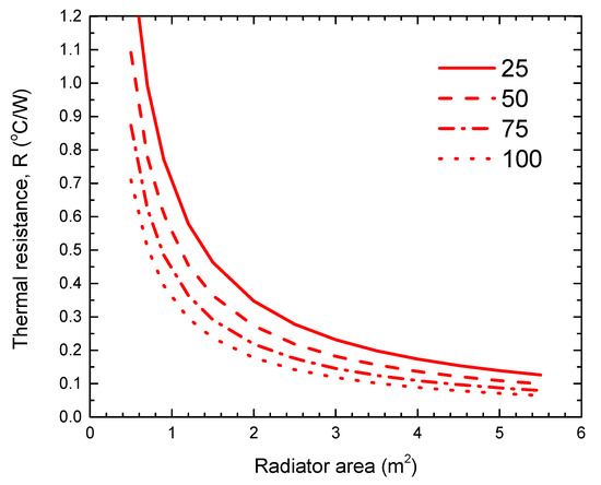
Figure 5.
Required radiator size that would enable a given thermal resistance, as a function of radiator temperature. The legend shows the radiators’ surface temperature in °C.
As expected, Figure 5 shows that the thermal resistance of the radiator reduces for a greater radiator temperature, or for a larger radiator area. What is also clear, is that a relatively large radiator is required to achieve a thermal resistance that would provide enough cooling to make a thermoelectric system viable. For example, for a radiator at 75 °C, a 1.4 m2 radiator would be required to achieve a thermal resistance of 0.3 °C/W. Given that CubeSats consist of units with approximately 0.1 m-long sides, meaning a radiator placed on a single 1 U surface is only 0.01 m2, it seems that many conditions where thermoelectric modules could provide a cooling benefit would be undermined by the requirement for an unrealistically large or complex radiator, e.g., a deployable radiator [2]. This calculation is also a best-case-scenario, since no thermal resistance for the thermal strap is included, i.e., essentially the radiator is in direct contact with the surface to be cooled. In reality the thermal strap would impose an additional thermal resistance.
It is therefore likely that, in the vast majority of cases, a thermoelectric system for CubeSat thermal management would not be feasible due to the large radiator that would be required, as well as the added complexity, mass and cost involved in the deployment of a thermoelectric system in the first place, which only provide benefit within a small range of operating conditions. That said, for this small range it is also possible that thermoelectric cooling could be used to actually reduce the radiator size. This idea is explored in another study by these authors [16].
Research aimed at improving thermoelectric modules is extensive and focuses on improving coefficient of performance. Indeed a significant COP enhancement would increase the range of operating conditions where thermoelectric cooling would be viable. This task in non-trivial however, since it relies on an improvement in thermoelectric material properties. These are inter-related, for example thermoelectric figure-of-merit improves by increasing electrical conductivity and decreasing thermal conductivity. Usually an increase in one, also increases the other, hence large improvements in this field are difficult to achieve.
4. Conclusions
An assessment was presented on the viability of using thermoelectric cooling for the thermal management of on-board electronics on CubeSats. A simple thermoelectric architecture was devised and a set of four empirical models for how such a system would perform were constructed, consisting of linear fits for the total heat dissipated at the hot-side of the thermoelectric module and the temperature difference (∆T) across the module, as a function of the heat pumped at the cold-side. The model used manufacturers’ performance data for a commercially available module. Models were used to calculate the temperature to which the system could cool a CPU, as a function of thermal resistance and heat rejection. As a baseline scenario, the temperature of the system without the thermoelectric module was compared and the benefit, or detriment, of using a thermoelectric module was deduced. Analysis showed that in some circumstances introducing a thermoelectric system would actually increase the temperature of the electronics being cooled. This is most common when the quantity of heat being removed, or the thermal resistance of the system, is high. Nevertheless, thermoelectric cooling is beneficial for a range of conditions, such as when cooling below ambient temperature. However, for the majority of CubeSat orbits, the initial CubeSat temperature is unlikely to be high enough to justify sub-ambient cooling, and the use of thermoelectric cooling for CubeSats may only be applicable in a small number of use cases. Even then, a radiator with low thermal resistance is required. This could undermine the thermoelectric device’s potential benefit in many cases, due to imposing the need for an unrealistically large radiator of several square-meters.
Future work should consider the feasibility of using thermoelectric systems for other space-based environments where the ability to cool below ambient would be of benefit, e.g., on the Moon or Mars, during the day time. Indeed, thermoelectric control has been demonstrated for such scenarios in the past, e.g., for the Mars Curiosity Rover, and further viability assessment of thermoelectric thermal management for rovers of various scales would be worthwhile.
Author Contributions
Conceptualization, N.S.B. and A.C.; methodology, N.S.B.; investigation, N.S.B. and A.H.; writing—original draft preparation, N.S.B.; writing—review and editing, N.S.B., A.H. and A.C. All authors have read and agreed to the published version of the manuscript.
Funding
This research received no external funding.
Institutional Review Board Statement
Not applicable.
Informed Consent Statement
Not applicable.
Data Availability Statement
Data from the study is available from the corresponding author by request.
Acknowledgments
NSB acknowledges the support of UTS’s Faculty of Engineering and Information Technology by way of participation in its Professional Experience Program, which allowed the time to carry out this study.
Conflicts of Interest
The authors declare no conflict of interest.
References
- Satellite Markets & Research. Available online: http://www.satellitemarkets.com/ (accessed on 24 February 2023).
- Donabedian, M.; Gilmore, D.G. Spacecraft Thermal Control Handbook; Aerospace Press: El Segundo, CA, USA, 2003; p. 253. [Google Scholar]
- Kandasamy, R.; Wang, X.-Q.; Mujumdar, A.S. Transient cooling of electronics using phase change material (PCM)-based heat sinks. Appl. Therm. Eng. 2007, 28, 1047–1057. [Google Scholar] [CrossRef]
- Alawadhi, E.; Amon, C. PCM thermal control unit for portable electronic devices: Experimental and numerical studies. IEEE Trans. Compon. Packag. Technol. 2003, 26, 116–125. [Google Scholar] [CrossRef]
- Sharma, C.S.; Zimmermann, S.; Tiwari, M.K.; Michel, B.; Poulikakos, D. Optimal thermal operation of liquid-cooled electronic chips. Int. J. Heat Mass Transf. 2012, 55, 1957–1969. [Google Scholar] [CrossRef]
- Mithal, P. Design of experimental based evaluation of thermal performance of a flipchip electronic assembly. ASME EEP Proc. 1996, 18, 109–115. [Google Scholar]
- Tua, Y.L.; Chu, R.C.; Janna, W.S. Thermal Management of Micro-electronic Equipment: Heat Transfer Theory, Analysis Methods, and Design Practices. Appl. Mech. Rev. 2003, 56, B46–B48. [Google Scholar]
- Brendel, L.P.M.; Hengeveld, D.; Braun, J.E.; Groll, E.A. Vapor Compression Cycles for High Component Heat Loads on Next-Generation Small Satellites. IOP Conf. Ser. Mater. Sci. Eng. 2019, 604, 012036. [Google Scholar] [CrossRef]
- Thermoelectric Cooling for Projection Lasers. Available online: https://lairdthermal.com/thermal-technical-library/application-notes/thermoelectric-cooling-laser-projectors/ (accessed on 2 May 2023).
- Tech Briefs: Engineering Solution for Design and Manufacturing. Available online: http://www.techbriefs.com/ (accessed on 24 February 2023).
- Semena, N.P. The features of application of thermoelectric converters in spacecraft systems of temperature control. Thermophys. Aeromech. 2013, 20, 211–222. [Google Scholar] [CrossRef]
- APHC-12706-S Peltier Cooler Module. Available online: https://www.farnell.com/datasheets/2548138.pdf (accessed on 24 February 2023).
- CubeSat Electrical Power System EPS. Available online: https://nanoavionics.com/cubesat-components/cubesat-electrical-power-system-eps/ (accessed on 24 February 2023).
- Piedra, S.; Torres, M.; Ledesma, S. Thermal Numerical Analysis of the Primary Composite Structure of a CubeSat. Aerospace 2019, 6, 97. [Google Scholar] [CrossRef]
- Howell, J.R.; Mengüç, M.P.; Daun, K.; Siegel, R. Thermal Radiation Heat Transfer, 7th ed.; Taylor & Francis Ltd.: Abingdon, UK, 2020; p. 231. [Google Scholar] [CrossRef]
- Bennett, N.S.; Lim, B. Assessing the Potential of Heat Pumps to Reduce the Radiator Size on Small Satellites. Energies 2023, 16, 4010. [Google Scholar] [CrossRef]
Disclaimer/Publisher’s Note: The statements, opinions and data contained in all publications are solely those of the individual author(s) and contributor(s) and not of MDPI and/or the editor(s). MDPI and/or the editor(s) disclaim responsibility for any injury to people or property resulting from any ideas, methods, instructions or products referred to in the content. |
© 2023 by the authors. Licensee MDPI, Basel, Switzerland. This article is an open access article distributed under the terms and conditions of the Creative Commons Attribution (CC BY) license (https://creativecommons.org/licenses/by/4.0/).