Article

Design of an Anthracite Creep Model Based on Fractional Order Theory: Experiments and Simulations

1
Department of Mining Engineering, College of Mining Engineering, Taiyuan University of Technology, Taiyuan 030024, China
2
College of Mechanical Engineering, Chongqing University of Technology, Chongqing 400054, China
*
Authors to whom correspondence should be addressed.
Appl. Sci. 2023, 13(11), 6522; https://doi.org/10.3390/app13116522
Submission received: 2 May 2023 / Revised: 21 May 2023 / Accepted: 25 May 2023 / Published: 26 May 2023

Abstract

:
Fractional order theory was used to characterize the accelerated creep phase of a nonlinear creep model. To accurately describe each stage of the anthracite creep model, the “gyroscope” unit was introduced by combining the Heaviside function and the creep damage definition. The effect of damage on anthracite creep was determined by designing and completing three-axis graded-separation loading creep tests on anthracite. The test curves were combined to classify anthracite into five stages: transient deformation, pseudo-acceleration, deceleration, isothermal, and acceleration creep. Each stage was combined with suitable components to form a combined fractional-order creep model. The one-dimensional equation of the state of the model was extended to three dimensions. The Levenberg–Marquardt optimization algorithm for fitting origin rheological curves was used to complete the fitting of the basic parameters. Finite differences were performed on the model equation of state, and a secondary development of a combined fractional-order creep model (NEG) was completed based on the built-in Burgers model in FLAC3D. A comparison of the numerical simulation results shows that the combined fractional-order creep model is important for accurately predicting the full creep stage of anthracite.

1. Introduction

Coal resources are the main energy source in China [1,2]. The consumption of coal resources is increasing year by year, and the mining depth of coal resources is gradually shifting from shallow to deep with the consumption of the shallow resources [3,4]. During deep mining in mines, most hard rocks exhibit the characteristics of soft rocks [5,6]. Due to the influence of “three highs and one disturbance”, strong dynamic pressure disturbances and soft fractures keep appearing in surrounding roadways [7,8,9,10,11]. The stability and safety of the roadway are challenged due to extrusion creep deformation [12,13] due to the surrounding rocks of the roadway exhibiting creep behavior [14,15,16,17]. In natural conditions, the creep behavior of the rock is subtle, but its rheological deformation constantly affects the stability of the roadway [18,19,20,21,22].
To study the rheological deformation characteristics of the coal rock mass, a large number of uniaxial and triaxial compression experiments have been used to determine the creep characteristics of the coal rock mass. For example, Z Jia et al. conducted triaxial compression experiments on coal samples at different depths and revealed the rule that the internal fracture size of coal samples decreases with increasing depth [23]. SG Zhang et al. developed a damage model based on the theory of minimum energy consumption [24]. G Peng et al. obtained the relevant data from creep tests based on a hydraulic servo test system and calculated the relevant parameters in the creep process based on fractional order calculus fitting [25]. Y Zhang et al. studied the permeability change of clastic rocks in creep experiments and revealed the effect of surrounding pressure on the permeability of the material [26]. Mansour et al. revealed the effect of rock expansion and fracture on the creep process through creep experiments with cyclic loading and unloading [27]. According to the different creep properties of coal rock bodies, creep models of coal rock bodies under various geological conditions have been studied and classified. At present, creep models are classified as linear and nonlinear creep models. According to existing studies and applications, to describe the various stages of the creep process, the linear model was modified by incorporating rock fracture damage theory. For example, Yan et al. modified the Nishihara model and the intrinsic equation to describe the accelerated creep phase of granite [28]. XB Li et al. developed the creep equation for water content based on the Burgers model [29]. GH Li et al. developed a modified Nishihara model by conducting shear creep experiments on mudstone [30]. Most of the intrinsic relationships of coal rock material show strong temporal properties, i.e., the intrinsic relationships of rock materials will change with time. The creep of the coal rock body, on the other hand, exhibits complex characteristics of nonlinear mechanics, and the linear model cannot express the nonlinear creep of the rock no matter what form the combination takes, i.e., the accelerated creep phase of the rock cannot be simulated, so the linear model has certain application limitations in expressing the creep phase of the coal rock body. Some researchers have recently introduced fractional order theory into the nonlinear model. For example, SQ Yang et al. combined the viscous unit of the Kelvin unit in the Nishihara model with the Abel damper (a linear component improved to a nonlinear component) to establish a constitutive equation [31]. XR Liu et al. proposed a new nonlinear viscous unit in combination with the Nishihara model, which can better respond to the accelerated creep phase of soft rocks [32]. JS Liu et al. established a quadratic creep model that can describe the creep of soft rocks based on fractional-order calculus theory and Abel’s dampers, combined with the special function of H-Fox [33]. At this stage, some researchers have added damage to the study of creep models. Mainly, Hou et al. carried out multi-load creep tests on sandstone at different damage levels and proposed a new rock damage model based on experimental data [34]. Liu et al. introduced damage variables in the differential principal structure equation based on the Kachanov creep damage rate and derived an analytical integral solution of the model creep damage equation [35]. New damage variables were also introduced. Ji et al. developed a damage intrinsic structure model based on damage mechanics theory and the statistical assumption of a normal distribution of rock strength [36]. The influence of internal friction variables on damage was analyzed. Yan et al. analyzed the effect of different L/D ratios on the damage energy evolution of the rock [37]. Meanwhile, a new intrinsic constitutive model was developed based on the friction energy parameters.
Fruitful results have been achieved regarding creep tests and creep models of rock masses. However, there is a lack of research on aspects such as the equation of state of the model suitable for coal. The purpose of this paper was to establish a model equation of state suitable for coal and to verify it by numerical simulation. In this paper, basic mechanical experiments and creep experiments were conducted with anthracite as the research object. The creep stages were specifically divided by creep experimental curves, and a combined creep model conforming to the lossy creep properties of anthracite was established by comparing the experimental curves of graded loading with those of individual loading. The model was extended in three dimensions and extended using Origin’s built-in Levenberg–Marquardt (L-M) optimization algorithm to fit the basic parameters of the model. On the basis that the anthracite creep equation was a finite difference equation, the code of the combined fractional-order creep model (NEG) was written in C++ based on the Visual Studio 2010 platform. The secondary development of the constitutive model was completed based on the domestic Burgers constitutive model in FLAC3D. Simulation validation by recovering the creep experimental conditions proved the correctness of software development and model parameter selection, providing a reference for the study of the anthracite creep model.

2. Materials and Methods

2.1. Preparation of Coal Specimens

The test anthracite was procured from the No. 3 coal seam of the Jushan coal mine in Jincheng, Shanxi Province. The standard specimens were processed and made using a ZS-100 drilling and coring machine (the equipment is from Mining Rock Testing Instrument Co., Jinan, China) and a TMS-1000 polishing instrument (the equipment is from Electromechanical Equipment Factory Co., Taizhou, China). To improve the reliability of the tests, specimens with obvious defects in appearance were excluded. An intelligent acoustic wave tester (the equipment is from Zhiyan Technology Co., Wuhan, China) was used to test the wave velocity of the experimental samples to exclude the influence of fissures and pores existing inside the coal samples themselves on the experimental results, and samples with wave velocity values of 2000–2300 m/s were taken for subsequent tests. After the coal samples were processed, the processed coal samples were wrapped with cling film to complete the maintenance of the coal samples. Table 1 shows the basic data of the coal samples.

2.2. Testing Equipment and Procedure

In this test, the MTS815.02 electro-hydraulic servo rock mechanics test system (the equipment is from MTS Systems, Eden Prairie, MN, USA) was used to conduct a conventional uniaxial, separately loaded creep test and a graded loaded creep test on sandy mudstone. The system has the basic uniaxial, conventional triaxial, and true triaxial test functions, which meet the requirements of this test.
Six wave velocity-treated samples were selected for loading creep tests. The surrounding pressure was set at 12 MPa. The stress initiation level was 50% of the peak strength of the triaxial tests on anthracite, i.e., the stress levels were 4.5 MPa, 5.2 MPa, 5.9 MPa, 6.6 MPa, 7.3 MPa, and 8.0 MPa. The first level of stress on the test samples was loaded at 4.5 MPa at a rate of 0.05 MPa/s. The creep was stabilized until the displacement value was less than 0.002 m/h. Then, the next level of loading was applied until the sample was deformed and damaged. The properties of the separately loaded test samples were due to their intrinsic properties and were not influenced by the historical loading.
In order to avoid the influence of the discrete shape of the specimen and the rock memory during loading on the creep results, the principle of the method in Figure 1 was used to process this test data. Specifically, the creep deformation generated at time Δt increases gradually after the application of load Δ σ . Specifically, after applying the load, the creep deformation generated in time t increased relative to the creep deformation at the end of the previous level of loading, and the creep deformation at this point was subtracted from the incremental creep deformation to obtain the corrected creep deformation. Various stress states with the same time step were applied to the same specimen, and 90% of the peak anthracite stress intensity was used as the total stress to determine the graded load. The stresses at each level were: 4.0 MPa, 5.0 MPa, 6.0 MPa, 7.0 MPa, and 8.0 MPa. The loading time for each level was t = 50 h to ensure that the specimen reached creep equilibrium or suffered creep damage.

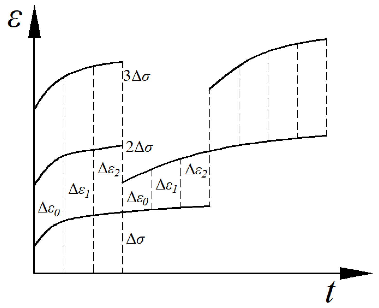
2.3. Definition of Creep Damage

Some of the existing research results suggest that there is no damage evolution in the creep phase prior to the accelerated creep phase of the coal rock mass [38,39,40]. Based on this and the above test results, it was shown that the creep grade of anthracite produced differences at different stress levels [41,42]. This phenomenon indicates that the internal mechanical parameters of the coal samples change during the initial creep stage. Therefore, Equation (1) was used to define the total damage of coal samples in this paper.
D = D σ + D t ,
where D σ denotes the initial damage and D t denotes the long-term damage.

2.3.1. Initial Damage

The creep parameters and variation characteristics of anthracite at the various stress levels are distinct. Therefore, Equation (2) was used to define the initial damage.
D σ = σ σ p λ ,
where σ denotes the current stress level of anthracite, σ p denotes the peak strength of anthracite (which can be obtained from the stress–strain curve), and λ denotes the damage parameter.

2.3.2. Long-Term Damage

After the anthracite enters the accelerated creep stage, keeping the stress level constant, the strain exhibits a significant nonlinear increase. This phenomenon is due to the dramatic evolution of the internal damage of anthracite at this time, which causes the creep parameters to change. Therefore, a change function containing time t was used to characterize the accelerated creep stage of anthracite. The time of the accelerated creep phase is treated with t c as the time origin. Equation (3) was used to define the long-term damage.
D t   =  e   λ t H t t c ,
where H () denotes the Heaviside function.

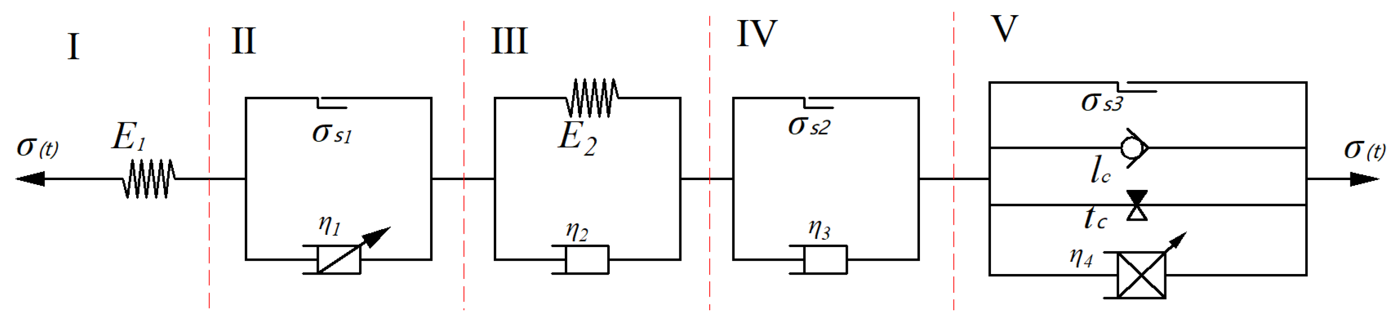
2.4. Combinatorial Model

On the basis of the classical model, a friction unit was used to characterize the stress threshold; an hourglass unit was used to characterize the time threshold. In this paper, a gyroscopic unit was proposed to characterize the displacement threshold. This means the model starts to act after the displacement reaches a certain level under the dual requirements of time and stress. That is, with the increase in loading time ( t ) , the creep curve changes after reaching a certain threshold value t c . In the time range of t~ t c , the internal displacement of a coal sample changes with the increase in loading stress and loading time ( t ) . Reaching a certain critical value, l c , the creep curve shows accelerated changes. According to the driving point of the accelerated creep phase of the creep curve, three conditions need to be satisfied to characterize the accelerated creep phase: σ σ s 3 , t t c ,  and  l l c . Based on the theory of fractional-order calculus, an improved fractional-order viscosity-plastic body based on the viscosity-plastic body model and Abel dampers combined with gyroscopic units was proposed. Figure 2 shows the general structure of the improved fractional-order viscosity-plastic body.
Based on the construction model, Equation (4) was used to represent the constitutive equation of the improved fractional-order viscosity-plastic body.
ε = 0 ,   σ < σ s 3 σ t σ s 3 = η α e λ t D α ε t ,           σ σ s 3 ,   t t c ,   l l c
According to the two-parameter Mittag–Leffler function property, the Laplace transform was calculated for Equation (4) when σ t = σ . Equation (5) was used to represent the improved fractional-order viscosity-plastic body creep equation [43,44].
ε ( t ) = 0 ,           σ < σ s 3 ε ( t ) = σ     σ s 3 η α H t t c H l l c α t α E 1 , 1 + α ( λ t ) ,           σ σ s 3
where η denotes the rock viscosity coefficient, α denotes the order, D () denotes the fractional-order derivative, and E 1,1 + α λ t = k   =   0 λ t k k   +   1   +   α .

2.5. Construction of Fractional Order Model for Anthracite Combinations

According to the classical creep test curve, the test sample exhibits transient mechanical morphology at the moment of loading; a Hook body was used to characterize this phase. The coal sample deformation exhibits a small, accelerated creep after the transient deformation, and then the coal sample creep rate increases; the fractional-order Bingham model was used to characterize this phase. This stage is called the “pseudo-accelerated creep stage”. After creep, the creep rate of the coal sample decreases; a Kelvin–Voigt body was used to characterize this stage (“decay creep stage”). When the stress level reaches a certain threshold, the coal sample enters the isokinetic creep stage; the Bingham model was used to characterize this stage. When the stress level exceeds a certain constant value and the time t and displacement l meet the requirements, the coal sample deformation enters the accelerated creep phase, and the strain rate of the coal sample increases significantly. In a relatively short period of time, the coal sample undergoes significant damage. A modified fractional-order viscoplastic body was used to characterize this phase. Figure 3 shows the general configuration of the NEG. The specific rheological forms are represented as: viscoplastic, viscoelastic, viscoplastic, and viscoplastic.
  • Hook body
The Hook body exhibits transient mechanical morphology when Model I is in effect. The internal damage evolution of anthracite under different stress levels varies, resulting in a partial discounting of mechanical properties compared to intact coal samples. Equation (6) represents the constitutive equation of the Hook body in a one-dimensional state.
σ 1 = E 1 ( 1 D ) ε 1 ,
where E denotes the modulus of elasticity.
2.
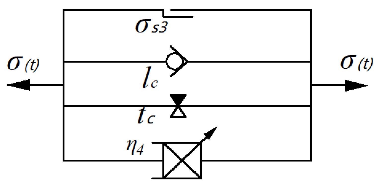
Fractional-order Bingham body
Model II produces an effect when the model enters the pseudo-accelerated creep phase, and the viscosity coefficients in the fractional-order Bingham body are discounted accordingly. Equation (7) is used to represent the fractional-order Bingham body constitutive equation in the one-dimensional state.
ε 2 = 0 ,   σ < σ s 1 σ ( t ) σ s 1 = ( 1 D ) η 1 α D α ε ( t ) ,   σ s 1 σ < σ s 2
When σ t = σ , Equation (8) is used to represent the fractional-order Bingham body creep equation.
ε 2 = 0 ,   σ < σ s 1 ε t = σ     σ s 1 1     D η 1 α t α Γ α   +   1 ,   σ s 1 σ < σ s 2
where Γ ( ) denotes the gamma function.
3.
Kelvin–Voigt body
When model III produces the action, the model enters the deceleration creep phase, and the elastic modulus and viscous coefficient in the Kelvin–Voigt body is discounted accordingly. Equation (9) is used to represent the Kelvin–Voigt body constitutive equation and creep equation in the one-dimensional state.
σ = E 2 ( 1 D ) ε 2 + η 2 ε 3 ˙ ε ( t ) = σ E 2 1 e E 2 η 2 t ,   σ s 1 σ < σ s 2
4.
Bingham body
Model IV produces the effect when the model enters the stable creep phase, and the viscosity coefficient in the Bingham body is discounted accordingly. Equation (10) is used to represent the Bingham body instanton equation in the one-dimensional state. Equation (11) is used to represent the Bingham body creep equation in its one-dimensional state.
ε 4 = 0 ,   σ < σ s 2 σ t σ s 1 = 1 D η 3 ε 4 ˙ ,   σ s 2 σ < σ s 3
ε 4 = 0 ,   σ < σ s 2 ε t = σ     σ s 2 1     D η 3 t ,   σ s 2 σ < σ s 3
In summary, the stress conditions were equal for each state condition, and the strain was equal to the sum of the accumulated strains in each component. Equation (12) is used to represent the creep constitutive equation in the one-dimensional state.
ε t 1 = σ E 1 ( 1 D ) ,   σ < σ s 1 ε t 2 = σ E 1 ( 1 D ) + σ σ s 1 ( 1 D ) η 1 α t α Γ α + 1 + σ E 2 1 e E 2 η 2 t ,   σ s 1 σ < σ s 2 ε t 3 = σ E 1 ( 1 D ) + σ σ s 1 ( 1 D ) η 1 α t α Γ α + 1 + σ E 2 1 e E 2 η 2 t + σ σ s 2 ( 1 D ) η 3 t ,   σ s 2 σ < σ s 3 ε t 4 = σ E 1 ( 1 D ) + σ σ s 1 ( 1 D ) η 1 α t α Γ α + 1 + σ E 2 1 e E 2 η 2 t + σ σ s 2 ( 1 D ) η 3 t + σ σ s 3 η β H t t c H l l c β t β E 1 , 1 + β λ t ,   σ σ s 3

2.6. Three-Dimensional Extension of NEG

In the burial depth conditions of the tunnel, the surrounding rock is in a three-directional stress state, and it is difficult to describe the creep characteristics of the tunnel using the one-dimensional creep equation. Therefore, the one-dimensional creep equation was extended into a three-dimensional creep equation.
The rock is in a three-dimensional stress state, and the stress state of any unit body inside it can be expressed by the stress sphere tensor σ m and the stress deflection tensor S i j . Equations (13) and (14) are used to represent the stress and strain expressions.
σ i j = δ i j σ m + S i j ,
ε i j = δ i j ε m + e i j
where δ i j denotes the unit tensor, δ i j = 1 0 0 0 1 0 0 0 1 ; σ m and ε m denote the stress and strain spherical tensor; and S i j and e i j denote the stress and strain bias tensor. Of which:
σ m = 1 3 σ 1 + σ 2 + σ 3 = 1 3 σ k k ,
ε m = 1 3 ε 1 + ε 2 + ε 3 = 1 3 ε k k ,
where σ k k denotes the volumetric stress and ε k k denotes the volumetric strain.
Equations (13) and (14) can be expressed as Equation (16).
S i j = σ i j 1 3 δ i j σ k k e i j = ε i j 1 3 δ i j ε k k ,
  • Hook body
In the three-dimensional stress state, based on the one-dimensional Hook’s law, Equation (17) can be obtained.
σ m = 3 K ε m S i j = 2 G e i j ,
where K = E 3 1 2 μ and G = E 2 1 + μ denote the bulk modulus and elastic modulus, respectively.
According to the three-dimensional stress rule, the ball stress tensor σ m remains largely independent of the creep state. The spherical stress tensor produces only a transient deformation. The creep of the coal sample is caused by the stress deflection tensor S i j . Equation (18) is used to represent the Hook body creep equation in its three-dimensional state.
S i j = 2 G 0 e i j ,
2.
Kelvin–Voigt body
The three-dimensional Kelvin–Voigt body creep equation is transformed from the one-dimensional creep equation in σ 0 to a constant bias stress S ( i j ) 0 . S ( i j ) 0 denotes the constant bias stress applied in the anthracite creep experiment. Equation (20) is used to represent the Kelvin–Voigt body creep equation in its three-dimensional state.
ε i j t a = 1 2 G a 1 e G a η a t S i j 0 ,
3.
Bingham body
A three-dimensional Bingham body should consider the plastic flow of the material. Equation (21) is used to represent the creep strain rate of the three-dimensional Bingham body.
ε i j t b = 1 η b F ϑ g ϑ σ i j t ,
where g denotes the potential function and F denotes the Heaviside function.
According to the creep equation in the one-dimensional state, the intermediate stress is equal to the minimum principal stress under the same enclosing pressure condition: σ 2 = σ 3 . Equation (22) is used to represent the stress spherical tensor σ m and the stress deflection tensor S i j .
σ m = 1 3 σ 1 + 2 σ 3 S i j = 2 3 σ 1 σ 3 ,
In summary, the creep equation of NEG in the three-dimensional state can be expressed by Equation (23).
ε t 1 = σ 1 + 2 σ 3 9 K 1 D + σ 1 σ 3 3 G 1 1 D ,   σ 1 σ 3 < σ s 1 ε t 2 = σ 1 + 2 σ 3 9 K 1 D + σ 1 σ 3 3 G 1 1 D + σ 1 σ 3 σ s 1 3 ( 1 D ) η 1 α t α Γ α + 1 + σ 1 σ 3 3 G 2 1 e G 2 η 2 t ,   σ s 1 σ 1 σ 3 < σ s 2 ε t 3 = σ 1 + 2 σ 3 9 K 1 D + σ 1 σ 3 3 G 1 1 D + σ 1 σ 3 σ s 1 3 ( 1 D ) η 1 α t α Γ α + 1 + σ 1 σ 3 3 G 2 1 e G 2 η 2 t + σ 1 σ 3 σ s 2 3 ( 1 D ) η 3 ,   σ s 2 σ 1 σ 3 < σ s 3 ε t 4 = σ 1 + 2 σ 3 9 K 1 D + σ 1 σ 3 3 G 1 1 D + σ 1 σ 3 σ s 1 3 ( 1 D ) η 1 α t α Γ α + 1 + σ 1 σ 3 3 G 2 1 e G 2 η 2 t + σ 1 σ 3 σ s 2 3 ( 1 D ) η 3 + σ 1 σ 3 σ s 3 3 η 4 β H t t c H l l c β t β E 1 , 1 + β λ t ,   σ σ s 3

2.7. Finite Difference of Equations

The creep components Hook body, fractional-order Bingham body, Kelvin–Voigt body, Bingham body, and modified fractional-order combination body are connected in series. The total stress is the same as the stress of each component, and the strain is the sum of the strains of the combined units. Equation (24) is used to represent the bias strain tensor and bias stress tensor of the model.
S i j = S i j H + S i j B 1 + S i j K + S i j B 2 + S i j B 3 e i j = e i j H + e i j B 1 + e i j K + e i j B 2 + e i j B 3 ,
where H , B 1 , K , B 2 , and B 3 denote model parts I, II, III, IV, and V, respectively.
According to the superposition principle, the rate of change of model bias strain can be expressed by Equation (25).
e i j ˙ = e i j ˙ H + e i j ˙ B 1 + e i j ˙ K + e i j ˙ B 2 + e i j ˙ B 3 ,
Equation (26) is an incremental expression of Equation (25).
Δ e i j = Δ e i j H + Δ e i j B 1 + Δ e i j K + Δ e i j B 2 + Δ e i j B 3 ,
The divergence form of the Hook body constitutive equation is expressed by Equation (27).
Δ e i j H = Δ S i j H 2 G 0 ,
The stress–strain relationship for a fractional-order Bingham body is represented by Equation (28).
ε i j B = H S i j σ s 1 2 G 1 t α Γ α + 1 ,
The total strain rate of a fractional-order Bingham body is expressed by Equation (29).
ε i j B = H S i j σ s 1 2 G 1 α t α 1 Γ α + 1 g σ i j ,
The deviator strain rate of a fractional-order Bingham body is expressed by Equation (30).
e i j ˙ B 1 = H S i j σ s 1 2 G 1 α t α 1 Γ α + 1 g σ i j 1 3 e v o l ˙ B 1 δ i j ,
In Equation (30):
e v o l ˙ B 1 = H S i j σ s 1 2 G 1 α t α 1 Γ α + 1 G 1 η 1 t α g σ 11 + g σ 22 + g σ 33 ,
The differential form of the fractional-order Bingham body is represented by Equation (32).
Δ e i j B 1 = H S i j σ s 1 2 G 1 α t α 1 Γ α + 1 g σ i j Δ t ,
Based on the assumption that only elastodynamics in plasticity causes volume changes, only the spherical stress update generated by the Kelvin–Voigt body causes creep strain. The ball stress–strain is expressed by Equation (33).
σ ˙ m = K B e ˙ k k B + K H e ˙ k k H ,
where K B   and   K H denote the rock bulk modulus.
The stress–strain relationship for the Kelvin–Voigt body is expressed by Equation (34).
S i j K = 2 G 2 e i j K + 2 η 2 e i j ˙ K ,
Based on the central difference principle, Equation (36) is converted to Equation (35).
S ¯ i j k = 2 G 2 e i j K + 2 η 2 e ¯ i j K ,
where S ¯ i j K = S i j K N + S i j K O 2 , e ¯ i j K = e i j K N + e i j K O 2 , and N and O denote the old and new quantity values within this Δ t .
Equation (35) is simplified to obtain Equation (36).
e i j K N = 2 η 2 2 η 2 + G 2 Δ t e i j K O 2 η 2 2 η 2 G 2 Δ t + Δ t 4 η 2 S i j K N + S i j K O ,
The incremental spherical strain of the Kelvin–Voigt body can be expressed in demonized Equation (37).
e m K N = 4 η 2 4 η 2 + 3 K 2 Δ t e m K O 4 η 2 4 η 2 3 K 2 Δ t + Δ t 8 η 2 σ m K N + σ m K O ,
Equation (38) is used to represent the strain rate in the one-dimensional state of the Bingham body.
e i j ˙ B 2 = H σ 0 σ s 2 η 3 ,
Equation (39) is used to represent the strain rate in the three-dimensional state of the Bingham body.
e i j ˙ B 2 = H σ 0 σ s 2 η 3 F σ i j ,
Equations (39) and (40) are used to express the bias strain rate of the Bingham body.
e i j ˙ B 2 = H σ 0 σ s 2 η 3 F σ i j 1 3 e i j ˙ B 2 δ i j ,
Equation (41) is used to represent the differential form of the Bingham body.
Δ e i j B 2 = H σ 0 σ s 2 η 3 F σ i j Δ t ,
Equation (42) is used to represent the deviator stress–strain relationship for the improved fractional-order combination.
e i j ˙ B 3 = H S i j σ s 3 2 η 4 β H t t c H l l c β β t β 1 ( k = 0 λ k k t k 1 ( k + 1 + β ) ) g σ i j 1 3 e v o l ˙ B 3 δ i j
Equation (43) is used to represent the differential form of the improved fractional-order combinator.
Δ e i j B 3 = H S i j σ s 3 2 η 4 β H t t c H l l c β β t β 1 ( k = 0 λ k k t k 1 ( k + 1 + β ) ) g σ i j Δ t
Bringing Equations (27), (32), (37), (41) and (42) into Equation (26), we can obtain Equation (44).
Δ e i j = A S i j N + Δ e i j B 1 + B S i j O + C e i j K O + Δ e i j B 2 + Δ e i j B 3 ,
Equation (45) is used to represent the total stress sphere tensor of the NEG model.
σ m N = σ m O + K B e k k B + K H e k k H ,
Equation (46) is used to represent the total stress increment at any point of the NEG model.
σ i j = σ m δ i j + S i j ,

2.8. Programming Outline

Based on the above finite difference form for constructing creep models, the required models were programmed in C++ (v.14.24.28127.4) through the Visual Studio 2010 platform. The combined fractional-order creep model (NEG) was developed based on the built-in Burgers intrinsic structure model of the FLAC3D (v.6.00.69) software. The main process includes:
  • Modifying the .h file by naming the model header file NEG.h, defining the file name as NEG, and modifying the model ID as 520.
  • Modifying the .cpp file, mainly by modifying the Strata function, Initialize function, and Run function, including the assignment of each material parameter.
  • Producing the .dll file by modifying the UDM folder to NEG, while copying it to the program installation location, opening the udm.veproj file, executing the udm command, modifying the debug/NEG.dll command, and finally running the solution. Figure 4 shows the numerical simulation model.

3. Results and Discussion
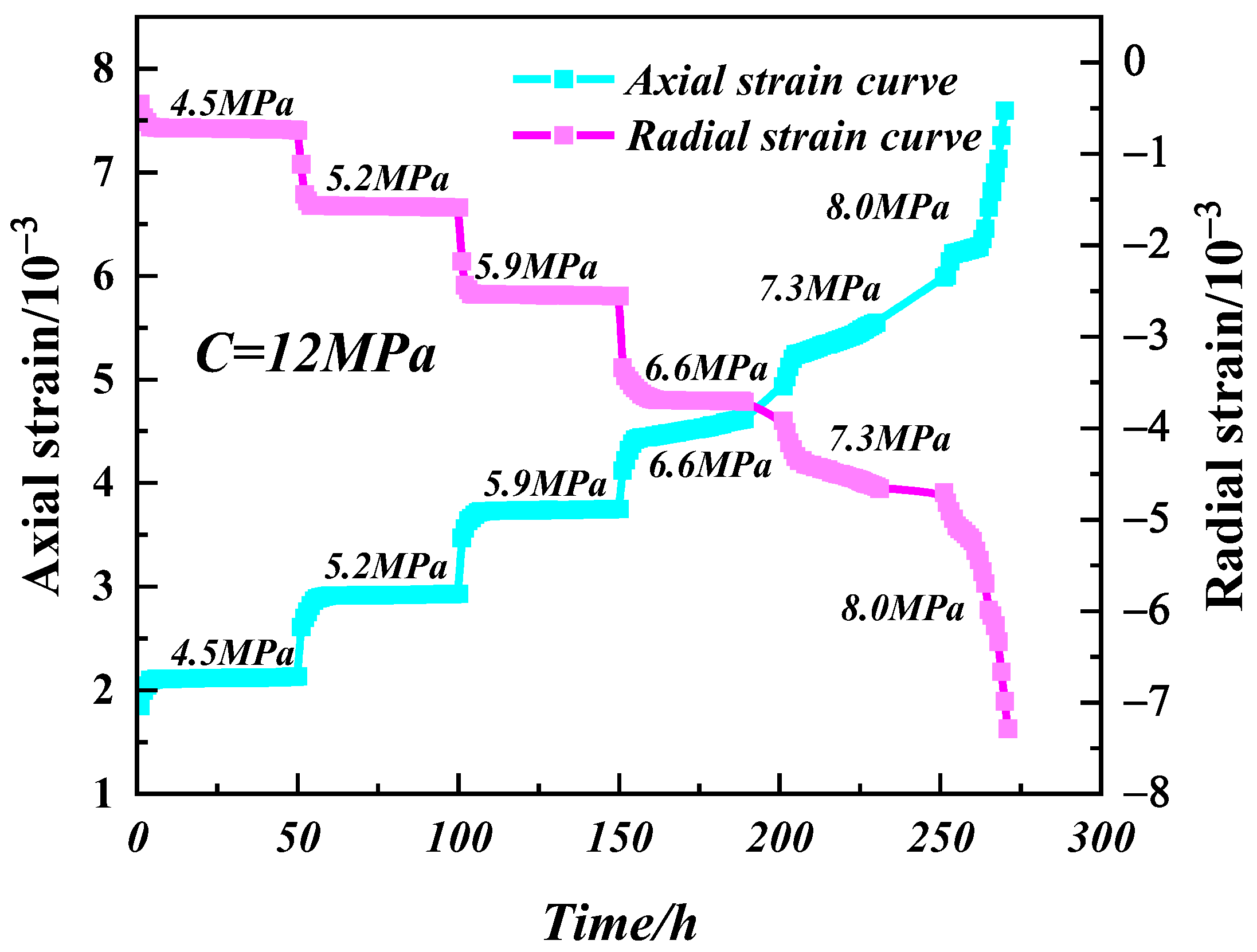
3.1. Test Results

According to the creep test, the creep test curves for separate loading and graded loading are shown in Figure 5 and Figure 6. The properties of the separately loaded experimental samples were related to their intrinsic properties and were not influenced by the historical loading [45,46,47,48]. The variation in the internal structure of the rock affects the results of the graded loading experiments [40,49,50,51].
From Figure 5 and Figure 6 it can be concluded that the creep change law of the specimen is basically the same, and the anthracite showed obvious instantaneous deformations at each level of loading, while the creep deformation increased continuously with time.
Transient deformation: Under different stress levels, the transient deformation of the axial strain and radial strain of the anthracite specimens showed a linear trend at the beginning, and with the increase in stress the strain gradually appeared to increase first and then decrease. The reason for this phenomenon is the existence of certain pores inside the anthracite. As the stress loading time increased, the pores inside the anthracite were compressed, and cracks gradually started to appear.
Creep deformation: Sample deformation increased with time at low creep stress levels. The specimen deformation curve was divided into a pseudo-accelerated creep phase and a decay creep phase. As the stress level increased and the time increased, the deformation curve appeared in the creep phase with equal speed, and the creep deformation became more obvious as the stress level and time increased. This phenomenon indicates that the increase in stress levels promotes the internal damage and fracture development of anthracite. Thus, the anthracite is more likely to suffer damage.
According to the graded loading creep curves, the anthracite did not show a significant accelerated creep phase in the first four stages, and there was one less creep stage compared to the separately loaded creep curves. The creep deformation damage occurred relative to the separately loaded creep. This indicates that the anthracite is gradually accumulating internal damage under the influence of historical loading in the case of graded loading, which changes the anthracite’s load-bearing capacity and promotes the deformation of the anthracite.
Under the conditions of the last level of stress, the experimental samples first exhibited transient deformation, pseudo-acceleration, deceleration, and isometric creep stages. With the increase in creep time, the curvature of the creep curve increased continuously. After the transition of the experimental sample’s deformation to the accelerated creep stage, the experimental sample suffered increasing damage as the creep time continued to increase.

3.2. Determination of Creep Model Parameters

According to Equation (22), to calculate any strain ε t it is necessary to determine the parameters K , G 1 , G 2 , α , η 1 , σ s 1 , σ s 2 , σ s 3 , η 2 , η 3 , η 4 , and β . Among them, K can be obtained from the creep experiment transient deformation data ( K = 1.012 GPa). σ s 1 denotes the beginning value of the creep of anthracite; σ s 2 denotes the beginning value of the creep of anthracite into isokinetic creep; and σ s 3 denotes the beginning value of the creep of anthracite into accelerated creep. σ s 1 , σ s 2 , and σ s 3 can be obtained according to the stress level at each stage in the graded loading creep experiment. σ s 1 takes the value of 10% of the deviator stresses, σ s 2 takes the value of 60–70% of the deviator stresses, and σ s 3 takes the value of 85–95% of the deviator stresses. The remaining parameters were fitted using the origin rheological curve fitting method. Equation (21) was written into the software, and regression inversion was performed on the basic parameters of the model based on the Levenberg–Marquardt (L-M) optimization algorithm. The known parameters such as K , G 1 , and σ s 1 were used in the fixed equation.
Table 2 shows the results of fitting the parameters of the anthracite creep model for the different partial stress states.

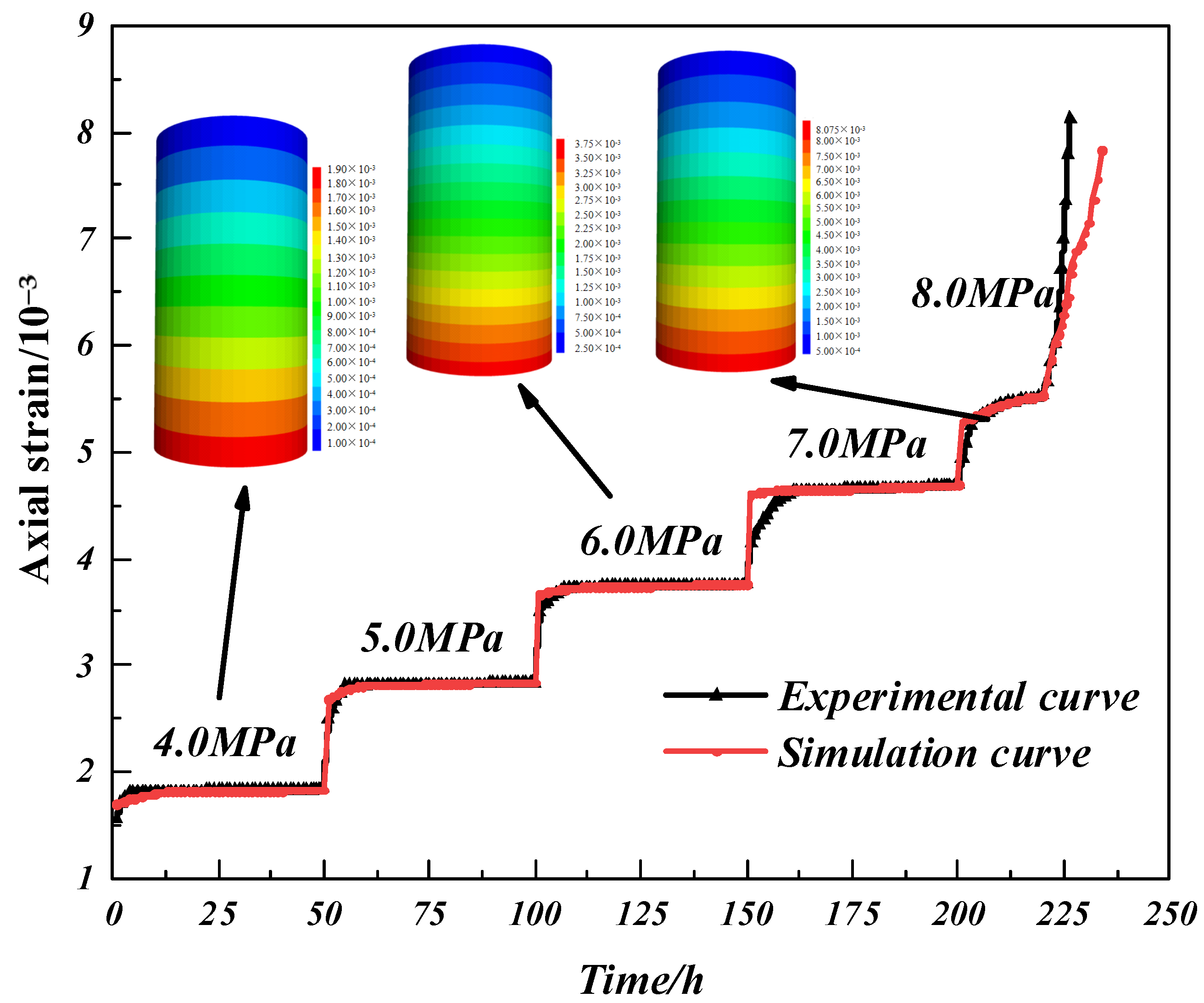
3.3. Simulation Verification

To verify the correctness and rationality of the NEG model, a secondary development of the FLAC3D software was carried out based on the Visual Studio 2010 platform. Based on the experimental samples of anthracite, the relevant numerical model was established. The model was divided into 8556 nodes and 8640 cells, and the vertical uniform load was applied at the top of the model, the Z-directional constraint force was applied at the bottom, and the fixed annular stress was applied laterally to simulate the surrounding pressure. The parameters related to Table 2 are written into the command program. The vertical displacement at the top of the model was recorded and converted to axial strain. Figure 7 shows the results of the numerical simulation compared with the creep experiments.
According to the experimental and simulation comparison curves, the creep test curves were in closer agreement with the numerical simulation curves at low loading stress levels as well as short creep time conditions. This is due to the fact that, in the first four stages before the accelerated creep curve is reached, the model selected a phase-applicable plastic–viscoplastic–viscoelastic structure, which is more reasonably described by the model for transient deformation and isokinetic deformation.
In the pseudo-acceleration–deceleration creep phase of the model, the inflection point of the combined fractional-order creep model curve was more obvious compared with the experimental creep curves at loading strengths up to 6 MPa and 7 MPa because the nodular development in the test samples has a certain influence on the strain of the experimental samples under loading conditions and the nodular fractured rock cannot be considered as a whole. In the combined fractional-order creep model, by considering the degradation effect of the nodal development on the sample, i.e., introducing the modifying variables of the nodal development in the pseudo-acceleration phase of the model, i.e., the parameters applicable to the parameter η 1 and the Gramma function, the nonlinear variation characteristics of more decay phases can be characterized by changing the different orders.
The test was conducted at 8 MPa, and the late creep stage of the experimental sample, i.e., the model creep, reached the accelerated creep stage, at which the creep test curve at the early accelerated creep stage was in better agreement with the numerical simulation experimental curve. In the late accelerated creep stage, the slope of the experimental creep curve basically remained unchanged, and the strain deformation increased, while the inflection point of the numerical simulation curve appeared due to the gradual accumulation of macroscopic damage in the experimental model under the condition that the stress remains constant while the loading time increases. The change in the accelerated creep stage parameters in the model equation can characterize the macroscopic changes of different experimental samples in the accelerated creep stage in a small range. According to the comparison of creep experimental curves and numerical simulation curves, the combined fractional-order creep model can be used to characterize the creep variation of anthracite.

4. Conclusions

  • Creep experiments using graded loading and separate loading of anthracite were designed, and the results show that the creep of anthracite under various levels of stress conditions exhibits the creep characteristics of transient deformation, pseudo-acceleration, deceleration, and isotropic acceleration, and the creep acceleration phase exhibits hysteresis characteristics.
  • Based on the Heaviside function, an improved fractional-order combinator was proposed by introducing the ‘gyroscope’ unit. Based on creep damage and the improved fractional-order combiner, a combined fractional-order creep model (NEG) that can describe the creep process of anthracite was proposed. The relevant parameters in this model were determined.
  • Based on the Burgers model built into FLAC3D, the secondary development of the NEG model was completed, and numerical simulations were performed with the fitted experimental parameters. The results demonstrated the success of the secondary development of the NEG model and the correctness of the parameter selection.
In conclusion, the NEG creep model can better characterize the creep properties of anthracite under different stress levels. However, it has some limitations for characterizing the creep properties of coal under special conditions (e.g., pore water pressure). In this paper, by studying the anthracite creep model and the large creep deformation problem in mines under deep mining conditions, an applicable model was established. By simulating the coal for a long time with strong dynamic pressure and other conditions, a reasonable support for the roadway deformation was further proposed, which better ensures the safety of mine workers and reduces the roadway maintenance cost at the same time. More importantly, this study provides some directions for the rational design of anthracite creep models.

Author Contributions

G.L.: Conceptualization, Data curation, Project management, Roles/Writing—original draft. G.Y.: Funding acquisition, Supervision, Writing—review & editing. S.K.: Funding acquisition, Supervision, Writing—review & editing. X.B.: Writing—review & editing, Data curation. C.D.: Data curation, Formal analysis, Software. J.L.: Investigation. J.Z.: Investigation. All authors have read and agreed to the published version of the manuscript.

Funding

This research was funded by the National Natural Science Foundation of China (Grant No. 51974195) and supported by Shanxi Provincial Department of Education’s 2022 Scientific and Technological Innovation Plan for Colleges and Universities in Shanxi Province-Project No.: 2022L055 and project support from Shanxi Science and Technology Department’s 2022 Basic Research Plan (Free Exploration)-Project No.: 20220302122099.

Institutional Review Board Statement

Not applicable.

Informed Consent Statement

Not applicable.

Data Availability Statement

The authors do not have permission to share data.

Conflicts of Interest

The authors declare that they have no known competing financial interests or personal relationships that could have appeared to influence the work reported in this paper.

References

  1. Li, S.C.; Wang, Q.; Wang, H.T.; Jiang, B.; Wang, D.C.; Zhang, B.; Li, Y.; Ruan, G.Q. Model test study on surrounding rock deformation and failure mechanisms of deep roadways with thick top coal. Tunn. Undergr. Space Technol. 2015, 47, 52–63. [Google Scholar] [CrossRef]
  2. Hao, J.; Li, X.L.; Song, Y.C.; Zhang, P.Z.; Liu, H.J. Analysis of mining roadway with large deformation of broken soft coal and research on supporting technology: A case study in Xin’an coal mine, China. Eng. Fail. Anal. 2021, 130, 105761. [Google Scholar] [CrossRef]
  3. Yang, S.Q.; Chen, M.; Jing, H.W.; Chen, K.F.; Meng, B. A case study on large deformation failure mechanism of deep soft rock roadway in Xin’An coal mine, China. Eng. Geol. 2017, 217, 89–101. [Google Scholar] [CrossRef]
  4. Zhang, Y.; Feng, G.; Zhang, M.; Ren, H.; Bai, J.; Guo, Y.; Jiang, H.; Kang, L. Residual coal exploitation and its impact on sustainable development of the coal industry in China. Energy Policy 2016, 96, 534–541. [Google Scholar] [CrossRef]
  5. Wang, Q.; Pan, R.; Jiang, B.; Li, S.C.; He, M.C.; Sun, H.B.; Wang, L.; Qin, Q.; Yu, H.C.; Luan, Y.C. Study on failure mechanism of roadway with soft rock in deep coal mine and confined concrete support system. Eng. Fail. Anal. 2017, 81, 155–177. [Google Scholar] [CrossRef]
  6. Zhu, S.Y.; Jiang, Z.Q.; Zhou, K.J.; Peng, G.Q.; Yang, C.W. The characteristics of deformation and failure of coal seam floor due to mining in Xinmi coal field in China. Bull. Eng. Geol. Environ. 2014, 73, 1151–1163. [Google Scholar] [CrossRef]
  7. Xu, J.K.; Wang, E.Y.; Zhou, R. Real-time measuring and warning of surrounding rock dynamic deformation and failure in deep roadway based on machine vision method. Measurement 2020, 149, 107028. [Google Scholar] [CrossRef]
  8. Wang, H.; Jiang, C.; Zheng, P.Q.; Zhao, W.J.; Li, N. A combined supporting system based on filled-wall method for semi coal-rock roadways with large deformations. Tunn. Undergr. Space Technol. 2020, 99, 103382. [Google Scholar] [CrossRef]
  9. Wang, H.; Jiang, C.; Zheng, P.Q.; Li, N.; Zhan, Y.B. Deformation and failure mechanism of surrounding rocks in crossed-roadway and its support strategy. Eng. Fail. Anal. 2020, 116, 104743. [Google Scholar] [CrossRef]
  10. Wang, H.W.; Xue, S.; Jiang, Y.D.; Deng, D.X.; Shi, S.Z.; Zhang, D.Q. Field Investigation of a Roof Fall Accident and Large Roadway Deformation Under Geologically Complex Conditions in an Underground Coal Mine. Rock Mech. Rock Eng. 2018, 51, 1863–1883. [Google Scholar] [CrossRef]
  11. Abul Khair, H.; Cooke, D.; Hand, M. Seismic mapping and geomechanical analyses of faults within deep hot granites, a workflow for enhanced geothermal system projects. Geothermics 2015, 53, 46–56. [Google Scholar] [CrossRef]
  12. Xu, X.H.; He, F.L.; Li, X.B.; He, W.R. Research on mechanism and control of asymmetric deformation of gob side coal roadway with fully mechanized caving mining. Eng. Fail. Anal. 2021, 120, 105097. [Google Scholar] [CrossRef]
  13. Sun, Y.T.; Li, G.C.; Zhang, J.F.; Qian, D.Y. Experimental and numerical investigation on a novel support system for controlling roadway deformation in underground coal mines. Energy Sci. Eng. 2020, 8, 490–500. [Google Scholar] [CrossRef]
  14. Wang, L.G.; Li, H.L.; Zhang, J. Numerical simulation of creep characteristics of soft roadway with bolt-grouting support. J. Cent. South Univ. Technol. 2008, 15, 391–396. [Google Scholar] [CrossRef]
  15. Yang, Y.R.; Lai, X.P.; Luo, T.; Yuan, K.K.; Li, G. Study on creep constitutive model of stratified siltstone and its application to instability analysis in mining. Environ. Earth Sci. 2022, 81, 270. [Google Scholar] [CrossRef]
  16. Zhu, Q.W.; Li, T.C.; Ran, J.L.; Du, Y.T.; Zhang, H.; Jiang, H. Model test on creep deformation and failure characteristics of soft rock roadways. Eng. Fail. Anal. 2022, 141, 106670. [Google Scholar] [CrossRef]
  17. Danesh, N.N.; Chen, Z.; Connell, L.D.; Kizil, M.S.; Pan, Z.; Aminossadati, S.M. Characterisation of creep in coal and its impact on permeability: An experimental study. Int. J. Coal Geol. 2017, 173, 200–211. [Google Scholar] [CrossRef]
  18. Shen, B.T. Coal Mine Roadway Stability in Soft Rock: A Case Study. Rock Mech. Rock Eng. 2014, 47, 2225–2238. [Google Scholar] [CrossRef]
  19. Chen, X.Y.; Wang, X.F.; Zhang, D.S.; Qin, D.D.; Wang, Y.; Wang, J.Y.; Chang, Z.C. Creep and Control of the Deep Soft Rock Roadway (DSRR): Insights from Laboratory Testing and Practice in Pingdingshan Mining Area. Rock Mech. Rock Eng. 2022, 55, 363–378. [Google Scholar]
  20. Huang, P.; Zhang, J.X.; Spearing, A.J.S.; Chai, J.; Dong, C.W. Experimental study of the creep properties of coal considering initial damage. Int. J. Rock Mech. Min. Sci. 2021, 139, 104629. [Google Scholar] [CrossRef]
  21. Jing, W.; Liu, S.X.; Yang, R.S.; Jing, L.W.; Xue, W.P. Mechanism of aging deformation zoning of surrounding rock in deep high stress soft rock roadway based on rock creep characteristics. J. Appl. Geophys. 2022, 202, 104632. [Google Scholar] [CrossRef]
  22. Wen, J.; Tang, Z.; Dyson, A.P.; Tolooiyan, A. The mechanical behaviour of pre-existing transverse cracks in lignite under uniaxial compression. Geomech. Geophys. Geo-Energy Geo-Resour. 2021, 7, 1–17. [Google Scholar] [CrossRef]
  23. Jia, Z.; Xie, H.; Zhang, R.; Li, C.; Wang, M.; Gao, M.; Zhang, Z.; Zhang, Z. Acoustic Emission Characteristics and Damage Evolution of Coal at Different Depths Under Triaxial Compression. Rock Mech. Rock Eng. 2020, 53, 2063–2076. [Google Scholar] [CrossRef]
  24. Zhang, S.G.; Liu, W.B.; Lv, H.M. Creep energy damage model of rock graded loading. Results Phys. 2019, 12, 1119–1125. [Google Scholar] [CrossRef]
  25. Peng, G.; Chen, Z.Q.; Chen, J.R. Research on Rock Creep Characteristics Based on the Fractional Calculus Meshless Method. Adv. Civ. Eng. 2018, 2018, 1472840. [Google Scholar] [CrossRef]
  26. Zhang, Y.; Liu, Z.B.; Xu, W.Y.; Shao, J.F. Change in the permeability of clastic rock during multi-loading triaxial compressive creep tests. Geotech. Lett. 2015, 5, 167–172. [Google Scholar] [CrossRef]
  27. Mansour, M.M.; Saad, G.; Wahab, L.A.; Fawzy, A. Indentation creep behavior of thermally aged Sn-5wt%Sb-1.5wt%Ag solder integrated with ZnO nanoparticles. J. Mater. Sci. Mater. Electron. 2019, 30, 8348–8357. [Google Scholar] [CrossRef]
  28. Yan, B.Q.; Guo, Q.F.; Ren, F.H.; Cai, M.F. Modified Nishihara model and experimental verification of deep rock mass under the water-rock interaction. Int. J. Rock Mech. Min. Sci. 2020, 128, 104250. [Google Scholar] [CrossRef]
  29. Li, X.B.; Liu, X.S.; Tan, Y.L.; Ma, Q.; Wu, B.Y.; Wang, H.L. Creep Constitutive Model and Numerical Realization of Coal-Rock Combination Deteriorated by Immersion. Minerals 2022, 12, 292. [Google Scholar] [CrossRef]
  30. Li, G.H.; Wang, Y.T.; Hu, Y.M.; Wang, D.; Yang, X.X.; Li, Y.F.; Zhou, Z.W.; Zhang, S.P. Shear creep mechanical properties and damage model of mudstone in open-pit coal mine. Sci. Rep. 2022, 12, 5148. [Google Scholar] [CrossRef]
  31. Yang, S.Q.; Jing, H.W.; Cheng, L. Influences of pore pressure on short-term and creep mechanical behavior of red sandstone. Eng. Geol. 2014, 179, 10–23. [Google Scholar] [CrossRef]
  32. Liu, X.R.; Yang, X.; Wang, J.B. A Nonlinear Creep Model of Rock Salt and Its Numerical Implement in FLAC(3D). Adv. Mater. Sci. Eng. 2015, 2015, 285158. [Google Scholar] [CrossRef]
  33. Liu, J.S.; Jing, H.W.; Meng, B.; Wang, L.G.; Yang, J.J.; Zhang, X.F. A four-element fractional creep model of weakly cemented soft rock. Bull. Eng. Geol. Environ. 2020, 79, 5569–5584. [Google Scholar] [CrossRef]
  34. Hou, R.; Zhang, K.; Tao, J.; Xue, X.; Chen, Y. A Nonlinear Creep Damage Coupled Model for Rock Considering the Effect of Initial Damage. Rock Mech. Rock Eng. 2019, 52, 1275–1285. [Google Scholar] [CrossRef]
  35. Liu, H.Z.; Xie, H.Q.; He, J.D.; Xiao, M.L.; Zhuo, L. Nonlinear creep damage constitutive model for soft rocks. Mech. Time-Depend. Mater. 2017, 21, 73–96. [Google Scholar] [CrossRef]
  36. Ji, M.; Chen, K.; Guo, H.J. Constitutive Model of Rock Uniaxial Damage Based on Rock Strength Statistics. Adv. Civ. Eng. 2018, 2018, 5047834. [Google Scholar] [CrossRef]
  37. Yan, X.; Jun, L.; Yijin, Z.; Shidong, D.; Tingxue, J. Research on Lateral Scale Effect and Constitutive Model of Rock Damage Energy Evolution. Geotech. Geol. Eng. 2018, 36, 2415–2424. [Google Scholar] [CrossRef]
  38. Lv, S.R.; Wang, W.Q.; Liu, H.Y. A Creep Damage Constitutive Model for a Rock Mass with Nonpersistent Joints under Uniaxial Compression. Math. Probl. Eng. 2019, 2019, 4361458. [Google Scholar] [CrossRef]
  39. Sha, Z.H.; Pu, H.; Li, M.; Cao, L.L.; Liu, D.; Ni, H.Y.; Lu, J.F. Experimental Study on the Creep Characteristics of Coal Measures Sandstone under Seepage Action. Processes 2018, 6, 110. [Google Scholar] [CrossRef]
  40. Zhou, J.X.; Zhang, J.W.; Wang, J.A.; Li, F.; Zhou, Y. Research on nonlinear damage hardening creep model of soft surrounding rock under the stress of deep coal resources mining. Energy Rep. 2022, 8, 1493–1507. [Google Scholar] [CrossRef]
  41. Feng, W.L.; Qiao, C.S.; Niu, S.J. Study on sandstone creep properties of Jushan Mine affected by degree of damage and confining pressure. Bull. Eng. Geol. Environ. 2020, 79, 869–888. [Google Scholar] [CrossRef]
  42. Huang, P.; Zhang, J.X.; Damascene, N.J.; Wang, Z.J.; Li, M. Effect of loading rate on mechanical behavior of coal samples with initial damage accumulation. Mech. Time-Depend. Mater. 2022, 26, 309–322. [Google Scholar] [CrossRef]
  43. Haubold, H.J.; Mathai, A.M.; Saxena, R.K. Mittag-Leffler Functions and Their Applications. J. Appl. Math. 2011, 2011, 298628. [Google Scholar] [CrossRef]
  44. Kilbas, A.A.; Koroleva, A.A.; Rogosin, S.V. Multi-parametric mittag-leffler functions and their extension. Fract. Calc. Appl. Anal. 2013, 16, 378–404. [Google Scholar] [CrossRef]
  45. Hamza, O.; Stace, R. Creep properties of intact and fractured muddy siltstone. Int. J. Rock Mech. Min. Sci. 2018, 106, 109–116. [Google Scholar] [CrossRef]
  46. Shan, R.L.; Bai, Y.; Ju, Y.; Han, T.Y.; Dou, H.Y.; Li, Z.L. Study on the Triaxial Unloading Creep Mechanical Properties and Damage Constitutive Model of Red Sandstone Containing a Single Ice-Filled Flaw. Rock Mech. Rock Eng. 2021, 54, 833–855. [Google Scholar] [CrossRef]
  47. Yang, S.Q.; Xu, P.; Ranjith, P.G. Damage model of coal under creep and triaxial compression. Int. J. Rock Mech. Min. Sci. 2015, 80, 337–345. [Google Scholar] [CrossRef]
  48. Zhang, Y.; Xu, W.Y.; Gu, J.J.; Wang, W. Triaxial creep tests of weak sandstone from fracture zone of high dam foundation. J. Cent. South Univ. 2013, 20, 2528–2536. [Google Scholar] [CrossRef]
  49. Zhang, J.X.; Li, B.; Zhang, C.H.; Li, P. Nonlinear Viscoelastic-Plastic Creep Model Based on Coal Multistage Creep Tests and Experimental Validation. Energies 2019, 12, 3468. [Google Scholar] [CrossRef]
  50. Zhang, Z.L.; Xu, W.Y.; Wang, W.; Wang, R.B. Triaxial creep tests of rock from the compressive zone of dam foundation in Xiangjiaba Hydropower Station. Int. J. Rock Mech. Min. Sci. 2012, 50, 133–139. [Google Scholar] [CrossRef]
  51. Sattar, M.; Othman, A.R.; Kamaruddin, S.; Akhtar, M.; Khan, R. Limitations on the computational analysis of creep failure models: A review. Eng. Fail. Anal. 2022, 134, 105968. [Google Scholar] [CrossRef]
Figure 1. Loading experimental data processing method.
Applsci 13 06522 g001
Figure 2. Improved fractional-order viscosity-plastic body model.
Applsci 13 06522 g002
Figure 3. Combined creep mode (I represents Hook body, II represents fractional order Bingham body, III represents Kelvin-Voigt body, IV represents Bingham body, and V represents Improved fractional order visco-plastic body).
Applsci 13 06522 g003
Figure 4. Numerical simulation model.
Applsci 13 06522 g004
Figure 5. Separate loading creep experimental curves.
Applsci 13 06522 g005
Figure 6. Creep experimental curve of graded loading.
Applsci 13 06522 g006
Figure 7. Variation law of axial strain with time under different stress conditions.
Applsci 13 06522 g007
Table 1. Tested anthracite specimens in this study.
SpecimenDiameter (mm)Height (mm)Mass (g)Density (g/cm3)Mt (%)
#149.2699.57301.251.58754.5216
#249.5699.85303.571.57604.3845
#349.8199.91304.821.56604.4257
Table 2. Parameter fitting results of the creep model.
Load (MPa) σ s 1
(MPa)
σ s 2
(MPa)
σ s 3
(MPa)
G 1
(GPa)
λ 1 η 1
(GPa/h)
G 2
(GPa)
λ 2
4.00.42.63.62.18318.41474.921.56727.312
5.00.53.254.51.035111.987434.4811.339410.7845
6.00.63.95.40.784117.5865151.02811.924415.8056
7.00.74.556.30.753928.90056.90491.090226.0005
8.00.85.27.20.922843.6168.0231.558358.86
η 2 (GPa/h) η 3 (GPa/h) λ 3 η 4 λ 4 α β R2
4.0406.39203.415.6094 0.6889 0.9375
5.0530.6958.7427.9916 0.3183 0.9620
6.0477.5623.364811.7123 0.3785 0.9904
7.040.0616.2919.267 0.7699 0.9911
8.0129.33610.772465.4320.9887.230.26590.42160.9930
Disclaimer/Publisher’s Note: The statements, opinions and data contained in all publications are solely those of the individual author(s) and contributor(s) and not of MDPI and/or the editor(s). MDPI and/or the editor(s) disclaim responsibility for any injury to people or property resulting from any ideas, methods, instructions or products referred to in the content.

