Article

Low Carbon Optimization of Deep Foundation Pit Support in Undulating Strata

1
Xi’an Research Institute of High-Tech, Xi’an 710025, China
2
School of Highway, Chang’an University, Xi’an 710064, China
*
Authors to whom correspondence should be addressed.
Appl. Sci. 2023, 13(11), 6562; https://doi.org/10.3390/app13116562
Submission received: 13 April 2023 / Revised: 23 May 2023 / Accepted: 24 May 2023 / Published: 28 May 2023

Abstract

:
To mitigate carbon emissions during the construction of deep foundation pit support in undulating strata, a theoretical calculation approach was utilized to design and compute the foundation pit support for Qingdao’s Metro Line 4. On this basis, the numerical simulation method is used to optimize the design scheme of foundation pit support with the surface deformation and the stress of the support structure. The results of numerical simulation show that the final ground settlement is 5.26 mm, the maximum horizontal displacement is 0.2836 mm, and the corresponding maximum shear force of the retaining pile is 250 kN, which is obviously superior to the ground settlement of 55 mm, 33 mm, and 1341.03 kN in the theoretical design. The use of simulation software before the construction and support of deep foundation pit excavation can reduce resource waste and achieve low-carbon design while ensuring construction safety.

1. Introduction

The advancement of urban development offers a favorable prospect for the investigation of deep foundation excavation support engineering. There are many problems in deep foundation pit support engineering in China, such as complex geological conditions and fluctuating strata. The existing foundation excavation support design approach is excessively cautious and fails to guarantee construction safety, leading to significant resource and material waste. Therefore, it is the only way for low-carbon geotechnical engineering to adopt reasonable methods to make the design of foundation pit support more refined.
At present, there are three design methods for foundation pit support. Zheng Gang et al. [1] used the limit balance method to analyze the failure mode of the single-row supported foundation pit and the influence of engineering piles in the pit on the stability of the foundation pit. Zhang Fei et al. [2] used the limit analysis method to study the stability of the foundation pit. Lv N [3] analyzed the design with the equivalent beam method of single fulcrum row piles in a deep foundation pit retaining structure. Zhang Jingxian et al. [4] proposed a vertical elastic foundation beam model to solve the problem of nonlinear correlation between earth pressure and support structure deformation in the design of deep foundation pit support structures. Xu jianqiang et al. [5] used an elastic foundation beam model to study the force of the support structure. With conventional design methods, the internal force can generally only be calculated, and it is difficult to calculate the deformation of the supporting structure. The third method is the finite element method, which is considered to be the most promising calculation method. Based on the foundation pit support design scheme, Li Lin [6] used the three-dimensional finite element dynamic process numerical simulation to study the impact of foundation pit excavation on the surrounding existing structures. Niu Jiandong et al. [7] established finite element analysis models to study the deformation of foundation pits. Hu Shengbin et al. [8] used the numerical simulation method to study the influence of the distance between the foundation pit and tunnel and the width and depth of foundation pit excavation on the stress of the tunnel bolt. Sun Yongshuai et al. [9] used FLAC3D 6.0, a three-dimensional finite-difference software simulation, to study the variation law of formation stress. Ample researchers have carried out research around the optimization of foundation pit engineering and proposed many optimization design methods, such as modern engineering mathematical methods [10], inverse analysis methods [11], and computer-aided design methods [12], Monte-Carlo stochastic simulation methods [13], numerical calculation methods [14], hybrid neural network methods [15], support vector machine approaches [16], projection pursuit methods [17], and system engineering optimization design methods [18]. In order to determine the relationship between influencing factors and the best bid plan, Shi, HW [19] developed an evaluation model for deep foundation pit support schemes based on UM. Most studies use only a single approach, and the optimization effect is not obvious. Furthermore, Lei Gang et al. [20] used an optimized MSD method to predict foundation pit deformation under specific formation conditions. Guangdong Han et al. [21] studied the internal process control of deep foundation pit engineering and the coordination of internal and environmental systems. According to the rule of the genetic algorithm, Wang Hui [22] designed the optimization design system of the pile anchor supporting structure in a deep foundation pit. These studies provide important guidance for the practical engineering application of foundation pit support.
Some scholars have used theoretical calculation and numerical simulation optimization design methods to study the deep foundation pit support, but most of the numerical simulation methods have given up the calculation accuracy in order to pursue the calculation efficiency, that is, simplifying the undulating strata to horizontal strata to establish a numerical model and carry out simulation. In order to improve the simulation accuracy, this paper establishes a numerical model of the volatile formation on the basis of theoretical calculations and uses the numerical simulation method to optimize the support scheme. In this way, the refined design of foundation pit support can be realized, the consumption of engineering resources can be reduced, and the low-carbon design can be realized.

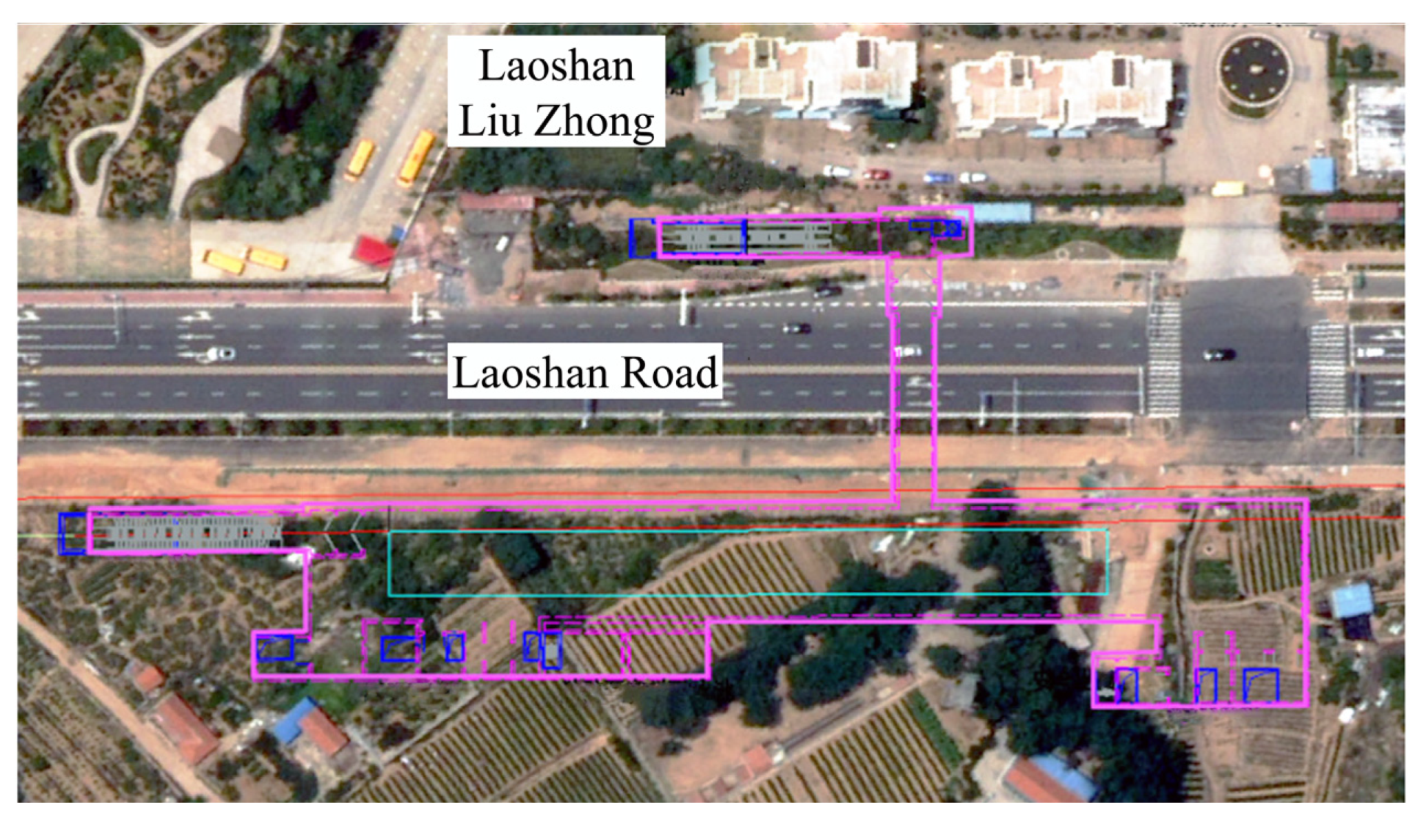
2. The Engineering Situation

2.1. Site Condition

The north side of the relying project is a school and residential area, and the south side is woodland and village collective land. The northern side of the foundation pit is adjacent to a 40-m-wide highway designed for a speed of 60 km/h. The rest of the pipelines have been rerouted, and there are no other buildings around. The excavation pit has a length of 168 m and a width of 27.3 m, with an average depth of approximately 28 m, resulting in an excavated area of 129,360 m2. The safety level of the foundation pit, taking into account both its surroundings and its own environment, is classified as level I, and the construction safety level is also level I. Therefore, a safety factor of 1.1, which is considered important, is applied. Figure 1 shows the surrounding environment of the foundation pit.
The construction site is situated within the Laoshan District of Qingdao. The landform along the line belongs to the denudation slope ~ intermountain flood alluvial landform. The formation parameters are shown in Table 1.

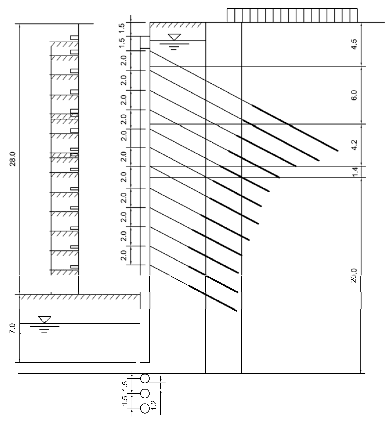
2.2. Support Design Scheme

The foundation pit support scheme employs the support form of anchor pulling in combination with internal support. The supporting structure comprises reinforced concrete bored piles and high-pressure rotary piles, with diameters of 1200 mm and 700 mm, respectively, and spacings of 1500 mm and 850 mm, respectively. The length of the bored pile is 35 m, and the concrete grade is C45. The steel mesh is φ8@200 mm × 200 mm and is hung between the piles, on which 100 mm thick C20 concrete is sprayed, and the reinforcement mesh is connected to form an integral water stop curtain.
The foundation pit is a relatively regular long strip foundation pit with three internal supports. The first one is a reinforced concrete beam, and the lower two are steel pipe beams. The grade of the concrete is C30, and prestress is applied. The 2.5-m-high soil layer is supported by a temporary enclosure. The first internal support is supported at 2.5 m underground, and the vertical spacing between the latter two is 7 m and 4 m, respectively. HRB400 steel bar is used as an anchor bolt, which is anchored by a nut and steel plate. Grouting material: cement mortar. Anchorage strength is not less than 25 MPa. The prestress locking value of the foot locking bolt is 500 kN. Information on foundation pit design is shown in Table 2.

3. Foundation Pit Support Scheme Design

3.1. Theoretical Calculation Design

3.1.1. Calculation Model

From Figure 2, it is apparent that the foundation pit has a depth of 28 m and utilizes a composite support system consisting of anchor piles and internal bracing. The pile length is 33.5 m, and three internal supports and twelve bolts are arranged. The parameters of the anchor bolt and internal support are shown in Table 3 and Table 4, respectively.

3.1.2. Calculation Working Conditions

Excavation of the foundation pit is carried out by the open excavation method, with simultaneous excavation and support. The design calculation is based on the parameters of the soil layer on site, including calculating the magnitude of the active soil pressure and determining the maximum depth at which the soil layer can remain stable after excavation. This is used to determine the depth of excavation for each layer. According to the engineering situation of reasonable engineering excavation layered calculation, finally achieve support completion. The working conditions are divided as shown in Figure 3.
The computer-aided design method is employed to calculate the supporting structure of the deep foundation pit, which involves the calculation of earth pressure, the design of equal section reinforcement of piles, the calculation of internal force and deformation, the calculation of anchor pile and bolt, the checking calculation of uplift resistance of the supporting pile, the checking calculation of overall stability, and the checking calculation of anti-overturning.

3.2. Numerical Simulation Optimization

3.2.1. Numerical Simulation Optimization Scheme

The theoretical calculation and design of the foundation pit revolve around the anchor pile and internal support structure. Due to the length of the pile (i.e., 35 m), the construction is inconvenient and costly. Therefore, it is recommended to use the numerical simulation method to optimize the structure based on local engineering experience. The southeast side of the foundation pit is high, and the corresponding load is large, so the steel pipe piles and anchor support are adopted. The anchor is pulled at the top of the steel pipe pile and 1.5 m underground. The rest of the upper part of the support is supported by reinforced concrete bored piles with a diameter of 1000 mm and a spacing of 1500 mm and jet grouting piles with a diameter of 900 mm and a spacing of 600 mm. The length of the pile is 13 m, and the grade of the concrete is C45.
The lower part of the foundation pit is supported by a φ168 @ 1500 steel pipe pile with a minimum insertion depth of 1.5 m and a pile length of 16.5 m. Additionally, prestressed anchors using HRB400 steel bars are installed to anchor 14 m below the top of the steel pipe pile.
The foundation pit is a regularly shaped, elongated pit with a concrete support as the initial support, measuring 1200 × 900 in size and made of C30 reinforced concrete. The second and third supports are constructed with φ800 mm and t = 20 mm steel tubes, with a vertical spacing of 7 m and 4 m, respectively, and a horizontal spacing consistent with the theoretical design. The bolts have a horizontal spacing of 1.5 m and an inclination angle of 15°. The specific parameters are presented in Table 5.

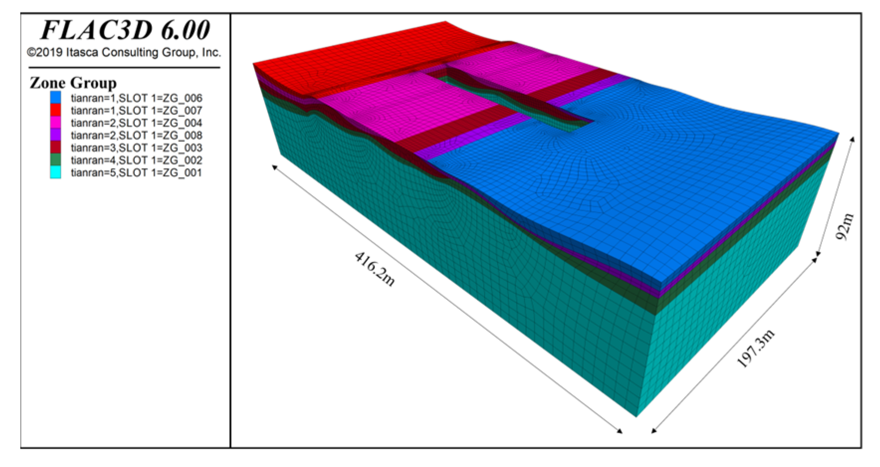
3.2.2. Foundation Pit Numerical Model

The excavation pit has a length of 168 m and a width of 27.3 m, with an average depth of approximately 28 m. The general length of the horizontal direction around the foundation pit in the model is about 3~4 times the side length of the foundation pit. The length of the depth direction of the model is 2~4 times of the depth of the downward extension foundation pit. Since the jet grouting pile is mainly used as a waterproof curtain, this study mainly focuses on the calculation of deformation and stress.
The foundation pit model is 416.5 m × 197.3 m × 92 m. The coordinate origin is located in the upper left corner of the proximal soil layer. The length of the grid element near the foundation pit is 1 m and 3 m in other positions. The numerical model has 162,039 grids in total, as shown in Figure 4.
(1)
Soil layer model and parameters
The Mohr–Coulomb constitutive relation model is used for the soil and rock mass model, so the Mohr–Coulomb theory is suitable for the stability of deep foundation pit excavation. Information on the soil layer is shown in Table 6.
(2)
Structural unit parameters
The structure includes an anchor rod and supporting pile. The parameters are as follows (Table 7, Table 8 and Table 9).

4. Calculation Results Comparison Analysis

4.1. Theoretical Design Calculation Results Analysis

The computer-aided design software is used to calculate the supporting structure of a deep foundation pit, including the deformation analysis of the foundation pit, the internal force analysis of the structure, and the overall stability analysis. According to the needs of design and construction conditions, the excavation calculation is carried out according to the division of labor.

4.1.1. Foundation Pit Deformation Analysis

The theoretical calculation of foundation pit settlement is mainly calculated by the parabolic method, the triangular method, and the exponential method. The results calculated by different methods are different. In the actual design, in order to ensure the safety of construction, the maximum value is taken as the design calculation. The results of the deep foundation pit are shown in Figure 5.
As shown in Figure 5, the maximum result calculated using the exponential method is 55 mm, while the result calculated using the triangular method is 37 mm, and the result calculated using the parabolic method is 29 mm. The settlement values of the deep foundation pit ground calculated by the three methods are within the range of 0.2% H (56 mm) allowed by the specification, but the settlement of the elastic method is too close to the standard. During the construction process, the reinforcement of the ground settlement of the long side wall should be strengthened as well.
In the analysis of the horizontal displacement of the foundation pit’s sidewall, the elastic method was employed to design the support structure. Based on the foundation pit’s ultimate working condition, it was determined that the maximum horizontal displacement of the support structure anchored with piles is 33.94 mm. This displacement value satisfies the requirement of the first-level deep foundation pit, which is set at 0.3% H.

4.1.2. Internal Force Analysis of Deep Foundation Pit Support

The internal force analysis of the deep foundation pit support structure primarily involves the application of classical and elastic methods. The internal forces of the supporting structure for the foundation pit are determined using the elastic fulcrum method, where the calculated values are multiplied by a safety importance coefficient of 1.25. Table 10 presents the maximum bending moments and shear forces on both the inner and outer sides of the foundation pit, while Table 11 displays the internal forces acting on the anchor rods.

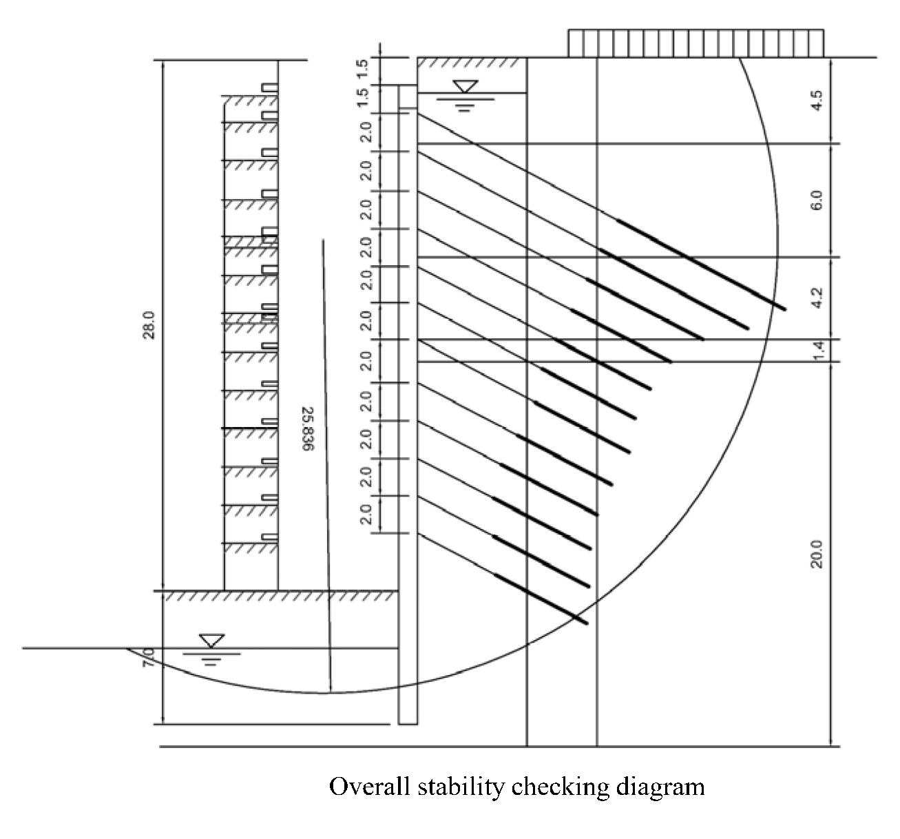
4.1.3. Overall Stability Analysis of Deep Foundation Pit

The comprehensive stability analysis of a deep foundation pit is determined using the Swedish slice method, and the calculation model is depicted in Figure 6. The calculation theory used is the total stress method of earth pressure, and the width of each soil band is 1.00 m. The radius of the sliding arc is 25.826 m, and the coordinates of the arc center are X = −5.592 m and Y = 17.927 m. The software computes the safety factor for the overall stability of the deep foundation pit to ensure that the foundation pit remains stable. According to the calculation of the minimum value analysis, it can be concluded that the overall stability safety factor of the foundation pit is Ks = 2.292 > 1.350, which meets the safety requirements of the specification.

4.2. Analysis of Numerical Simulation Optimization

The simulation analysis of deep foundation pit support construction is to simulate the unloading process of rock and soil mass under actual conditions, but the unloading stress paths of different heights and different parts of the foundation pit are completely different. Based on the principle of finite difference, FLAC3D 6.0 has the capability to model excavation processes and display changes in displacement and stress.

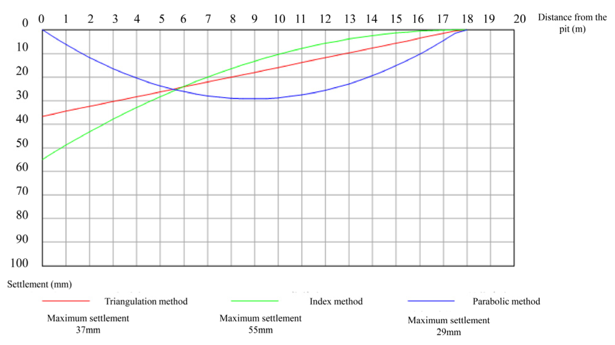
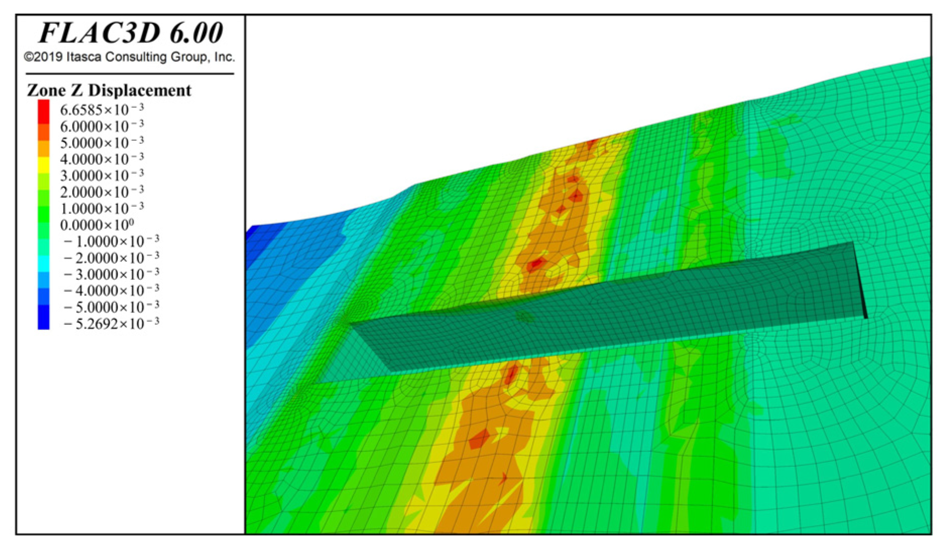
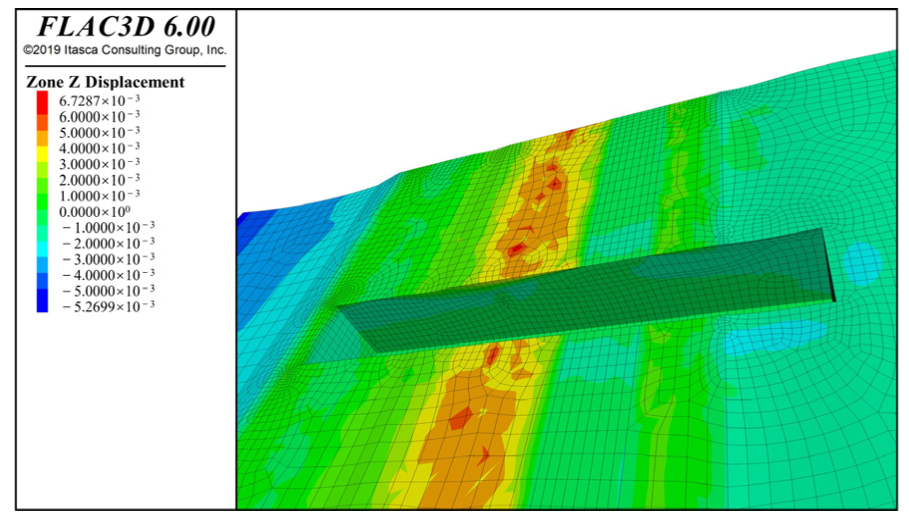
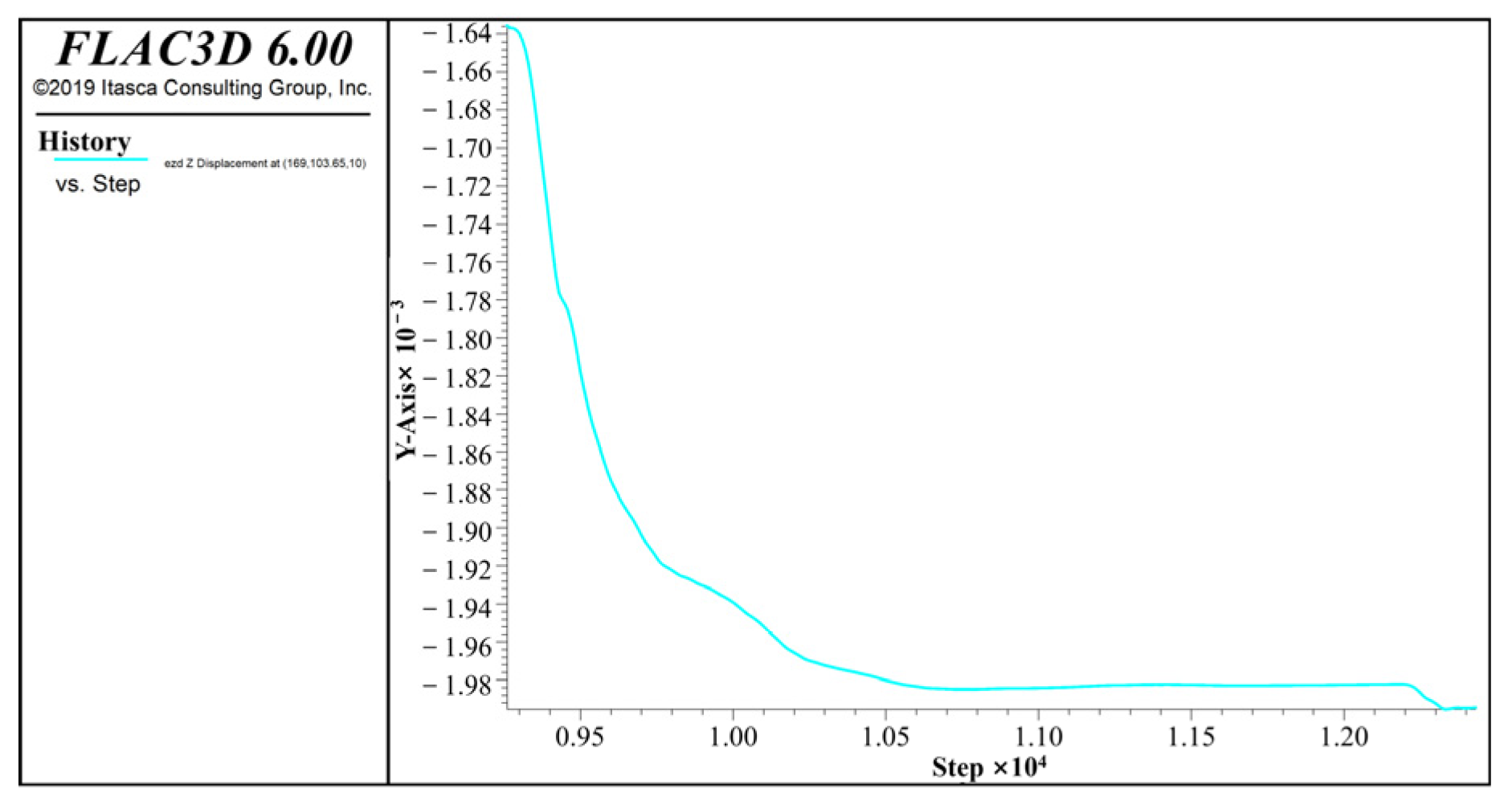
4.2.1. Results of Foundation Pit Settlement

The construction process for the deep foundation pit supported by bored piles involves first leveling the site and subsequently executing the pile support construction. After the supporting pile is added to the model, the displacement of the foundation pit unit soil is shown in Figure 7. The strata are uneven; the overlying soil layer is plain fill, and the lower soil layer is granite. As a result of the high elevation in the center of the foundation pit, after site leveling measures are taken, the gravitational stress of the soil is relieved, resulting in an upward displacement of the ground surface with a maximum settlement of 6.58 mm. After driving into the retaining pile, the soil settlement under the foundation pit changes slightly, and the maximum downward settlement displacement of the model is 5.26 mm.
The excavation of the foundation pit adopts the NULL model, and the settlement of the first inner support is shown in Figure 8. From the side wall of the foundation pit, it can be seen that the settlement inside the foundation pit is almost unchanged due to the action of the supporting pile, which indicates that the supporting pile bears almost all the earth pressure. With the increase in excavation depth, it is obvious that the supporting pile alone cannot maintain the stability of the foundation pit. Therefore, it is necessary to apply internal support and an anchor rod to share the shear force of the supporting pile.
The addition of internal bracings significantly reduces the internal force of retaining piles and limits the horizontal displacement of excavation. When FLAC3D 6.0 simulation is carried out, the beam element is used to represent the internal support simulation. The displacement when the internal support is added is shown in Figure 9. Taking into consideration the analysis of the obtained results, it can be concluded that, in addition to the uplift caused by the previous site leveling, the maximum land subsidence is 5.26 mm.
Finally, the supporting effect of the bolt is simulated. The bolt element is used to reduce the stress on the pile foundation and the inner support, and the durability of the supporting structure is increased. A prestress of 500 kN is applied to the bolt. The displacement settlement after adding the bolt is shown in Figure 10. The observation of Figure 10 reveals that the ground settlement does not change, and the bolt shares part of the shear force of the supporting pile.
Monitoring points in numerical models are established in the center of the long side of the foundation pit, and Figure 11 illustrates the settlement changes observed throughout the entire construction process. The midpoint settlement of the foundation pit is gradually increasing with the excavation. As the settlement of the support structure is gradually improved by the side wall, the displacement curve becomes gentle. After the support is completed, the curve is stable, and the maximum surface settlement of the midpoint at the long side of the foundation pit is 2.12 mm.

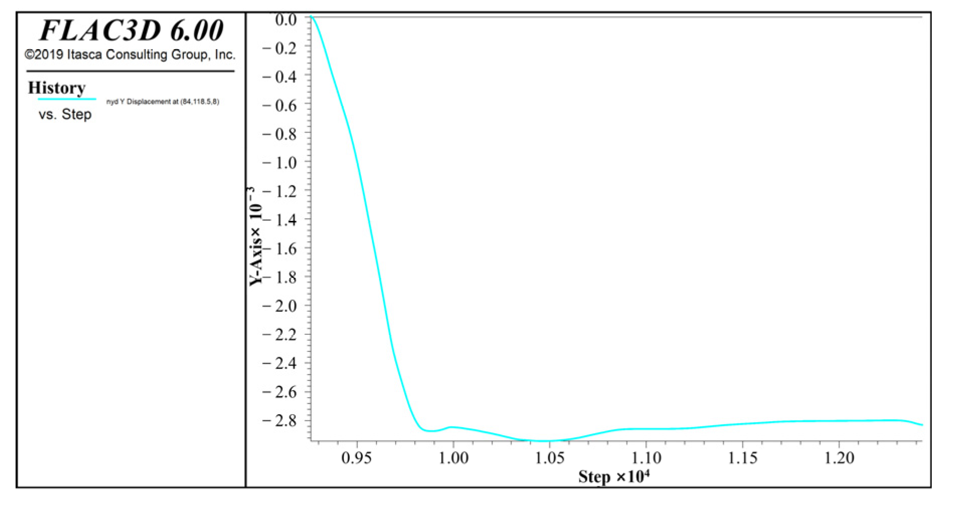
4.2.2. Horizontal Displacement of Foundation Pit Sidewalls by Numerical Calculation

Prior to the excavation of the deep foundation pit, supporting piles are driven into the ground first, resulting in minimal horizontal displacement of the foundation pit’s sidewalls following excavation. The horizontal displacement of the side wall of the foundation pit gradually increases with the excavation of the foundation pit. The horizontal displacement of the surface in the middle of the long side of the foundation pit is shown in Figure 12. As a consequence of stress redistribution resulting from the excavation of the foundation pit, horizontal soil displacement begins to increase. Upon excavation to the bottom, maximum horizontal displacement deformation is attained. The change in maximum horizontal displacement decreases with the improvement of supporting structures. The horizontal displacement of the middle section of the foundation pit’s long side gradually decreases and approaches a state of stability. The final stable displacement of the supporting structure measures 0.2836 mm, complying with the deformation requirements specified for the foundation pit.

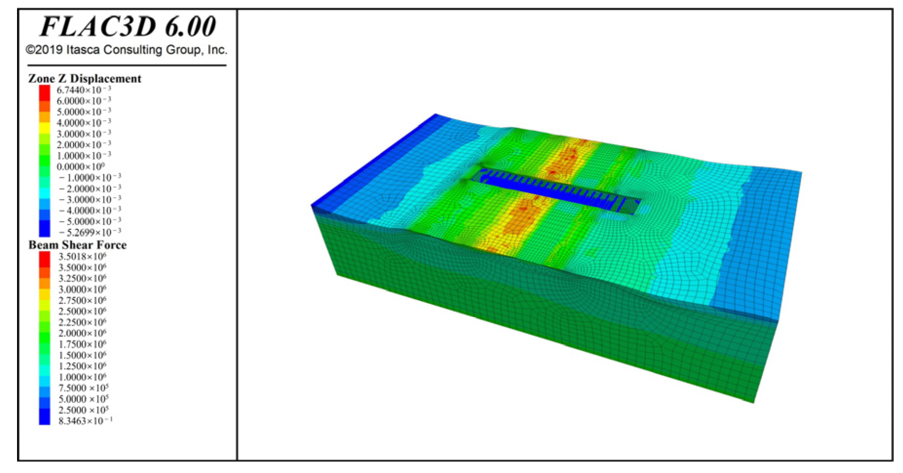
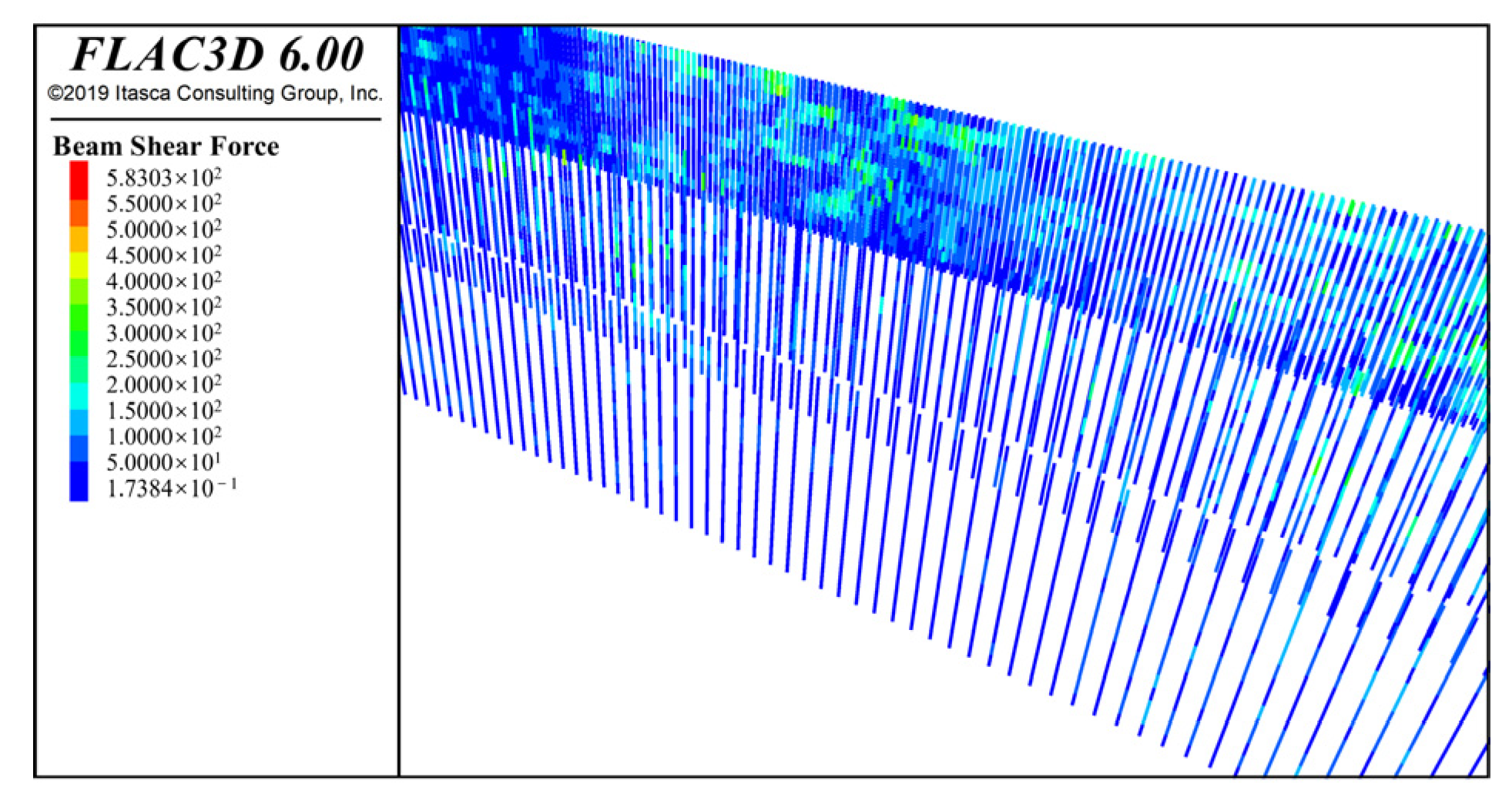
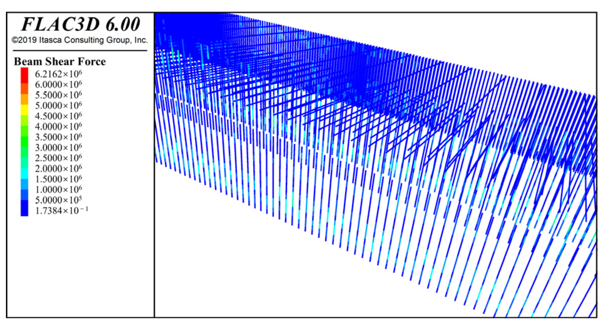
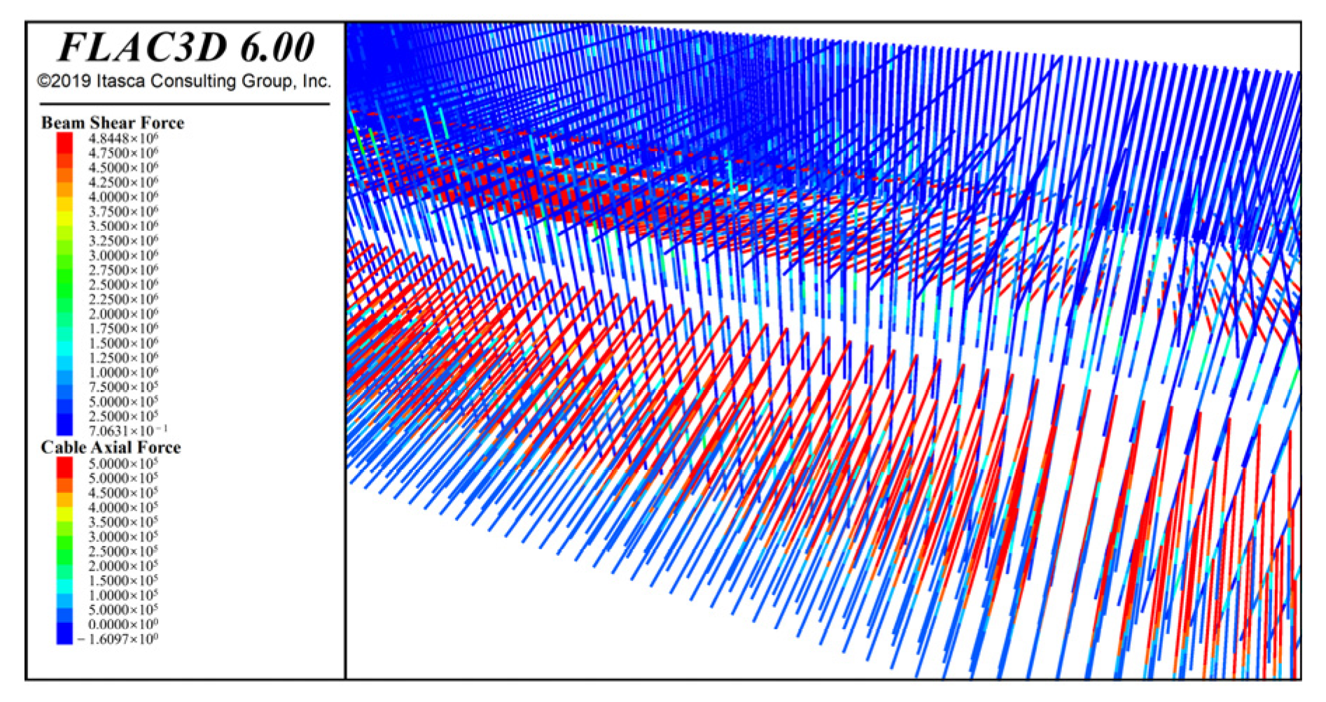
4.2.3. Results of the Internal Force of Structural Element Simulation

When the foundation pit is not excavated, the force exerted on the supporting pile can be disregarded. Subsequent to the excavation of the foundation pit, the supporting pile constrains the deformation of the foundation pit’s sidewall and is subject to lateral soil pressure. The force of the supporting pile is shown in Figure 13. At this time, no internal support is added, and the soil pressure borne by the supporting pile is very uneven. The shear force of the supporting pile is 1.75 × 10⁶ N, and the maximum shear force of the single pile is 1.341 × 10⁶ N in design calculation. The simulated shear force obviously exceeds the calculated value, which is unfavorable to the structure.
When the inner support is added, it can be seen that the pile force is not only reduced but also becomes very uniform, and the inner support balances the earth pressure on both sides. The internal support and supporting pile force are shown in Figure 14. It can be seen from the figure that the shear force in the supporting pile is 1 × 10⁶ N, and the maximum shear force in the design value of the supporting pile is 1.341 × 10⁶ N. The shear force is significantly reduced.
Upon the inclusion of the anchor rod, Figure 15 illustrates the force acting on the supporting structure. Due to the addition of the anchor rod, the maximum shear force of the pile unit is reduced, and the shear force of most piles is 0.25106 N. As a result of implementing the anchor rod, the internal force exerted on the supporting pile decreases and the supporting capacity of the anchor-pile structure increases. Compared with the design value of 1.341106 N, the diameter of the pile can be reduced. According to material quantity estimation, the material can be saved by about 20%. The maximum force of the anchor rod is prestress and appears in the anchor pull section.
The simulation results of the optimization scheme show that the optimized supporting structure has a good constraint effect on the deformation of the foundation pit. There are 6 anchor rods, and the longest supporting pile is 16.5 m, which is far less than the length of a single pile in the design calculation. The maximum shear force of the supporting pile is 1.25 × 10⁶ N, which is less than the shear force of 1.341 × 10⁶ N calculated by design. The maximum force of the inner support is 2 × 10⁶ N, which is less than the maximum internal force value of 2.69 × 10⁶ N in the design calculation. The maximum force of the bolt is 0.5 × 10⁶ N, which is less than the maximum force of 0.8 × 10⁶ N in the design calculation. All of them meet the requirements for foundation pit support and foundation pit deformation. The optimized design scheme is reasonable and effective.

5. Conclusions

The deep foundation pit support is theoretically designed through software utilization, and numerical simulations are performed to optimize the support scheme. The following conclusions are drawn:
(1)
Computer-aided software is used to design the supporting structure of the deep foundation pit. The maximum settlement of the foundation pit is 55 mm, which is less than 0.2% of the depth of the foundation pit (56 mm). The maximum horizontal displacement of the foundation pit is 33.94 mm, which is less than 0.3% of the depth of the foundation pit (84 mm). The maximum shear force of the supporting pile is 1341.8 kN, and the maximum internal force of the anchor rod is 1295.88 kN;
(2)
The numerical simulation method is used to establish a three-dimensional deep foundation pit model, and the support scheme is optimized. The final settlement of the surface, the maximum horizontal displacement, and the force of the support structure are less than the design value of the theoretical calculation;
(3)
This paper combines computer-aided design software and numerical simulation software and plays to their respective advantages. Computer-aided design software has great advantages in the selection of supporting forms, and numerical simulation can intuitively reveal the stress and displacement changes of the foundation pit structure. The combination of the two can not only improve efficiency but also reduce the waste of resources. While improving the design economy, it greatly saves resources and achieves low-carbon design.

Author Contributions

Methodology, Y.L. and J.X.; Software, J.L.; Writing—original draft, X.W. and H.X.; Writing—review & editing, W.W. and Z.Z. All authors have read and agreed to the published version of the manuscript.

Funding

This research was funded by the National Natural Science Foundation of China (Grant number 41807245), the Science and Technology Plan Project of Housing and Urban-Rural Construction in Shaanxi Province (Grant No.2022-K53) and Foundation of Hubei Key Laboratory of Blasting Engineering (No. BL2021-08).

Informed Consent Statement

Not applicable.

Data Availability Statement

Our data can be made available upon request. Please feel free to contact us for more information on data availability and how to access it. If you have any questions or require further assistance, please do not hesitate to reach out to us.

Conflicts of Interest

The authors declare no conflict of interest.

References

  1. Zheng, G.; Zhang, T.; Cheng, X.S. Effect of foundation piles on excavation stability and its calculation. Chin. J. Geotech. Eng. 2017, 39, 5–8. (In Chinese) [Google Scholar]
  2. Zhang, F.; Li, J.; Tang, Y. Basal-heave stability of excavations considering groundwater level and pore water pressure fluctuations by upper bound method. Rock Soil Mech. 2011, 32, 3653. [Google Scholar]
  3. Lv, N.; Hui, M.L. The research of the single row piles designing in deep foundation pit. In Proceedings of the 2015 International Conference on Advanced Engineering Materials and Technology, Guangzhou, China, 22–23 August 2015. [Google Scholar]
  4. Zhang, J.X.; Yang, Q.; Feng, Z.J. Deep foundation pit supporting structure considering pile-soil interaction Elastic foundation beam method. Highw. Traffic Technol. (Appl. Technol. Ed.) 2020, 16, 140–142. [Google Scholar]
  5. Xu, J.Q.; Xu, J.B.; Yang, X.H.; Yan, Z.; Li, H.; Wang, H.; Tan, L.; Fei, D.; Li, J.; Luo, Y. Elastic Foundation Beam Solution of Tensile Flexible Retaining Wall. Int. J. Steel Struct. 2022, 22, 622–631. [Google Scholar]
  6. Li, L.; Li, B.; Liu, D.; Han, X. Study on the Influence of Large Irregular Deep Foundation Pit Excavation on Adjacent Buildings in the Soft Soil. Area J. Yangtze River Sci. Res. Inst. 2023, 1, 140–145. (In Chinese) [Google Scholar]
  7. Niu, J.; Li, Z.; Feng, C.; Wang, B.; Chen, K. Combined support system and calculation model for deep foundation pits in fill soil areas. Arab. J. Geosci. 2020, 13, 347. [Google Scholar] [CrossRef]
  8. Hu, S.; Zhou, T.; Zhong, Y.; Ji, X.; Sun, S.; Lin, J.; Zhang, R.; Wang, Z.; Guo, C.; Lin, H. Influence Law of Foundation Pit Excavation on Stress of Surrounding Tunnel Bolt. Appl. Sci. 2022, 12, 11479. [Google Scholar] [CrossRef]
  9. Sun, Y.S.; Li, Z.M. Analysis of Deep Foundation Pit Pile-Anchor Supporting System Based on FLAC3D. Geofluids 2022, 2022, 1699292. [Google Scholar] [CrossRef]
  10. Guo, F.S.; Liu, Z.D. Optimization Design of Bracing Project of Deep Foundation Pit at the First Yangtza River’s. Build. Struct. 2000, 11, 51–54. (In Chinese) [Google Scholar]
  11. Feng, S.; Xin, Y.H. Optimum Design for The Bracing Structure with Double-row Piles of Deep Foundation Pit. Optim. Cap. Constr. 2001, 6, 32–34. (In Chinese) [Google Scholar]
  12. Liu, C.Q. Spoke Method of Soil-Nail Bracing Structure and Its Optimization. Master’s Thesis, Xi’an University of Architecture and Technology, Xi’an, China, 2006. [Google Scholar]
  13. He, Z.M.; Wang, P.P.; Wang, L.J.; Zhang, Y.; Chen, Y.C. Deformation evolution law and optimization design of huge deep foundation pit excavation. J. Chang. Univ. Sci. Technol. (Nat. Sci.) 2022, 19, 69–77. [Google Scholar]
  14. Chang, H.; Chen, L. Optimum selection of supporting scheme for deep foundation pit based on fuzzy mathematics theory. J. Jilin Jianzhu Univ. 2019, 36, 23–31. (In Chinese) [Google Scholar]
  15. Deng, R.; Zhou, L. Optimising the supporting structure of a bridge’s foundation pit based on hybrid neural network. Int. J. Crit. Infrastruct. 2022, 18, 159–171. [Google Scholar] [CrossRef]
  16. Zhou, Y.; Su, W.J.; Ding, L.Y.; Luo, H.; Love, P.E.D. Predicting Safety Risks in Deep Foundation Pits in Subway Infrastructure Projects: Support Vector Machine Approach. J. Comput. Civ. Eng. 2017, 31, 04017052. [Google Scholar] [CrossRef]
  17. Zhang, L.; Li, H.B. Construction Risk Assessment of Deep Foundation Pit Projects Based on the Projection Pursuit Method and Improved Set Pair Analysis. Appl. Sci. 2022, 12, 1922. [Google Scholar] [CrossRef]
  18. Sun, J.C.; Bai, T.H. Construction Control System of Mechanical State of Metro Deep Foundation Pit in Soft Soil. Tunn. Constr. 2019, 39, 44–52. (In Chinese) [Google Scholar]
  19. Shi, H.; Du, J.; Yang, J. Multi-Objective Optimization of Supporting Plan for Deep Foundation Using Entropy-Based Um-Dea; Czech Technical University in Prague-Central Library: Prague, Czech Republic, 2019. [Google Scholar]
  20. Lei, G.; Gong, X.N. Analysis of Lateral Displacement Law of Deep Foundation Pit Support in Soft Soil Based on Improved MSD Method. Adv. Civ. Eng. 2021, 2021, 5550214. [Google Scholar] [CrossRef]
  21. Han, G.D.; Guan, C.S.; Zhou, J. Environmental Impact and Hazard Control Method on Deep Foundation Pit Supporting Engineering. Adv. Mater. Res. 2013, 2195, 978–982. [Google Scholar] [CrossRef]
  22. Wang, H. Effect of genetic algorithm in optimizing deep foundation pit supporting structure. Arabian J. Geosci. 2021, 14, 266. [Google Scholar] [CrossRef]
Figure 1. The surrounding environment of the foundation pit.
Applsci 13 06562 g001
Figure 2. Calculation model of foundation pit support.
Applsci 13 06562 g002
Figure 3. Excavation information for working conditions.
Applsci 13 06562 g003
Figure 4. Numerical model of the foundation pit.
Applsci 13 06562 g004
Figure 5. Ground subsidence results of the deep foundation pit.
Applsci 13 06562 g005
Figure 6. The overall stability checking diagram of the deep foundation pit.
Applsci 13 06562 g006
Figure 7. Settlement diagram after pile driving.
Applsci 13 06562 g007
Figure 8. Settlement of the pit without internal support after excavation.
Applsci 13 06562 g008
Figure 9. Settlement diagram of foundation pit with internal support after excavation.
Applsci 13 06562 g009
Figure 10. Ground subsidence after adding an anchor rod.
Applsci 13 06562 g010
Figure 11. Midsettlement of the foundation pit.
Applsci 13 06562 g011
Figure 12. Horizontal displacement of the monitoring points by numerical calculation.
Applsci 13 06562 g012
Figure 13. Stress of the supporting pile without internal support.
Applsci 13 06562 g013
Figure 14. Internal support and support pile joint force.
Applsci 13 06562 g014
Figure 15. Structural unit force.
Applsci 13 06562 g015
Table 1. Mechanical parameters of soil.
No.HydrogeologyDepth/mγ/(kN·m−3)c/kPaφ/°qsik/kPa
1Plain fill4.518162020
2Coarse-grained sand with clayey soil4.220.5938120
3Strongly weathered granite1.4237.543180
4Moderately weathered granite2.75261655400
5Slightly weathered granite1526.52265800
Table 2. Information on foundation pit design.
Foundation Pit Depth H/mEmbedment Depth/mConcrete StrengthPile Diameter/mPile Spacing/mCrown Beam Width/mCrown Beam Height/mOverload/kPa
287C451.21.511.220
Table 3. Parameters of anchor support.
NumberSupport Anchor TypeHorizontal Spacing (m)Vertical Spacing (m)Angle of Incidence (°)Overall Length (m)Length of Anchorage Section (m)
1internal bracing9.0001.500---------
2Anchor Rod1.5001.50025.0024.009.50
3Anchor Rod1.5002.00025.0023.5010.00
4Anchor Rod1.5002.00025.0020.007.50
5Anchor Rod1.5002.00025.0019.007.50
6internal bracing3.0000.500---------
7Anchor Rod1.5001.50025.0016.506.00
8Anchor Rod1.5002.00025.0015.506.00
9internal bracing3.0000.500---------
10Anchor Rod1.5001.50025.0015.006.00
11Anchor Rod1.5002.00025.0014.006.00
12Anchor Rod1.5002.00025.0013.006.00
13Anchor Rod1.5002.00025.0012.506.00
14Anchor Rod1.5002.00025.0012.506.00
15Anchor Rod1.5002.00025.0012.506.00
Table 4. Information on internal support.
NumberSupport TypeHorizontal Spacing (m)Vertical Spacing (m)
1Reinforced concrete internal support91.5
2Steel pipe supports37
3Steel pipe supports34
Table 5. Numerical simulation of anchor support information.
NumberAnchor TypeHorizontal Spacing/mVertical Spacing/mAngle of Incidence/°Overall Length/mLength of Anchorage Section/m
1Anchor Rod1.5002.00015.0013.007.00
2Anchor Rod1.5002.00015.0013.007.00
3Anchor Rod1.5002.00015.0013.006.00
4Anchor Rod1.5002.00015.0012.006.00
5Anchor Rod1.5002.00015.0012.006.00
6Anchor Rod15.0002.00015.0012.006.00
Table 6. Information on the soil layer.
NumberNameγ/(kN·m−3)c/kPaφ/°Young’s Modulus/MpaPoisson’s Ratio
1Plain fill18001610230.3
2Coarse-grained sand with clayey soil2050927320.25
3Strongly weathered granite23007.53090000.23
4Moderately weathered granite2600164015,0000.17
5Strongly weathered granite2650224822,0000.14
Table 7. Support pile parameter information.
NumberNameDistance from the Ground/mYoung’s Modulus/(×105 Mpa)Poisson’s RatioCross-Sectional Area/m2
1Bored Pile1.53.20.2823
2Steel pipe piles143.50.37
Table 8. Anchor rod parameter information.
Young’s Modulus/(×105 Mpa)Compressive Strength/kNTensile Strength/kNCross-Sectional Area/(×10−4 m2)
2.130030003.14
Table 9. Support parameter information.
NumberNameDistance from the Ground/mYoung’s Modulus/(×105 Mpa)Poisson’s RatioCross-Sectional Area/m2
1Reinforced concrete beams1.50.30.31.08
2Steel pipe beam8.53.550.270.502
3Steel pipe beam11.53.550.270.502
Table 10. Maximum shear and bending moment values for the inside and outside of deep foundation pit.
Internal Force TypeCalculated Value by Elastic MethodClassical Method of Calculating ValuesInternal Force Design ValuePractical Value of Internal Force
Maximum bending moment inside foundation pit (kN·m)2504.242146.622926.832926.83
Maximum bending moment outside foundation pit (kN·m)2358.812207.472756.862756.86
Maximum shear force (kN)1325.291040.691822.271822.27
Table 11. Maximum internal force values of anchor rod.
Anchor Road NumberMaximum Internal Force Elasticity Method (kN)Maximum Internal Force Classical Method (kN)
10.00385.71
2300.008.00
3450.0010.00
4400.0012.00
5550.00128.33
6300.00128.33
7450.0010.00
8450.0012.00
9550.00128.33
10800.0010.00
11800.0010.00
12800.0010.00
13800.0015.00
14750.0015.00
15550.0015.00
Disclaimer/Publisher’s Note: The statements, opinions and data contained in all publications are solely those of the individual author(s) and contributor(s) and not of MDPI and/or the editor(s). MDPI and/or the editor(s) disclaim responsibility for any injury to people or property resulting from any ideas, methods, instructions or products referred to in the content.

