Abstract
Recently, to resolve a growing need for durable and resilient railway bridge construction/reconstruction systems, a great amount of research has been carried out in many countries. As a part of such studies, prefabricated composite girders with an innovative girder-to-deck connection have been proposed that facilitate construction by eliminating interference during on-site processes. In this study, a railway bridge prototype of prefabricated composite girders with girder-to-deck connections was designed to facilitate future application enhancement of off-site construction. Then, prefabricated composite girders were developed by deploying different girder-to-deck connections through geometric detailing of reinforcement, headed stud connectors, and precast decks. Based on the calculation theory of interface shear transfer, the detailed design of different girder-to-deck connections was carried out, in particular the reinforcement spacing. Furthermore, finite element analysis of prefabricated composite girders was conducted to determine the flexural moment strength of prefabricated composite girders. Parametric studies were carried out to consider the factors affecting the detailed design of the connection, ensuring that the connection is correctly designed, thereby ensuring the structural performance of prefabricated composite girders. From the results, conclusions were drawn. The developed cases satisfied the interface shear criteria according to both conventional and plastic approaches. There was no significant difference in flexural moment strength between the developed cases since all cases were designed with the full shear connection. In all cases, the flexural performance was ensured and can be used for railway bridges. The most optimum case of prefabricated composite girders is selected in specific design situations.
1. Introduction
Innovative off-site constructions utilizing prefabricated bridge elements (PBEs) are continuously being developed. Although prefabricated systems have been utilized for many different types of bridge members, prefabricated bridge deck elements have emerged as one of the more popular applications. To accelerate construction, prefabricated bridge deck elements have been utilized since the 1970s [1]. The initial deployment was primarily utilized in deck replacement projects when rapid project delivery was required, to reduce interference with local traffic in densely populated areas. Prefabricated bridge deck elements have since been studied extensively in both field inspection studies, and laboratory investigations [2,3]. The connection material is the first feature influencing the performance of prefabricated bridge deck elements. To be used in field-cast connections, many commercially available grouts have been tested. Previous studies on grout materials have mainly focused on dimensional stability, bond strength to precast concrete, durability, constructability aspects, and new properties [4,5]. The next feature is the surface preparation of prefabricated bridge deck elements at the connection location. Digital images were utilized by Santos et al. [6] to evaluate the surface roughness level in precast concrete with as-cast, sandblasted, and wire-brushed surface preparations. It was found that as the surface roughness level of precast concrete increased, the bond between cast-in-place and precast concrete improved remarkably. Graybeal [7] reported a similar result. Finally, the performance of prefabricated bridge deck elements is greatly affected by the connection details between elements. With the increasingly efficient development of the above influencing factors, full-depth deck panel systems became the best choice. The full-depth deck panel system with stud connector clusters embedded in shear pockets is a typical system. However, there are many matters to resolve when utilizing stud connector clusters such as the shear connection [8,9], consisting of deck uplift, nonuniform shear stress distribution, and local bearing failure of grout in the shear pockets. The use of continuous void connections is an expected resolution, instead of point connections. Graybeal [10] suggested composite girders with prefabricated deck panels connected to precast concrete girders through the injection channels. Experiments were also conducted to investigate the bending behavior of this prefabricated girder and the connection performance. The good results from these experiments indicate that this is a potential connection type for prefabricated bridge elements. Therefore, prefabricated composite girders, with the steel girders and deck panels connected by injecting mechanical grout into a continuous channel above the steel girders to achieve composite action between the steel girders and deck panels, were proposed by Diep et al. [11], as shown in Figure 1. Such connection of prefabricated composite girders is typically made by means of shear connectors placed within a partial depth block-out in the deck panels. This type of block-out solved concerns about durability compared to a full depth block-out, since the full depth block-out has exposed joints around the perimeter of the block-out after the grout is placed. The top deck reinforcement can be placed over the block-out, which simplifies the layout of reinforcement in the deck panel. In addition, the continuous connection will allow more closely-spaced shear connectors, and uniform shear stress distribution. Greater haunch height can be advantageous for the flow of grout under the deck panels and adjustment during precast deck module installation and connection. Because of such outstanding advantages, this type of connection needs more research attention to accelerate its applicability. In this study, a design of the railway bridge prototype using prefabricated composite girders was conducted. Additionally, prefabricated composite girders were developed by deploying different new innovative girder-to-deck connections through geometric detailing of reinforcement, stud connectors, and precast decks, and their detailed design was carried out based on the calculation theory of interface shear transfer, especially the design of spacing between bars of reinforcement connecting the precast deck and the grout which controls the connection design. Furthermore, finite element analysis of prefabricated composite girders was conducted to determine the flexural moment strength of prefabricated composite girders. Parametric studies were carried out to consider the factors affecting the detailed design of the connection, ensuring that the connection is properly designed, and thereby ensuring the structural performance of the prefabricated composite girder.
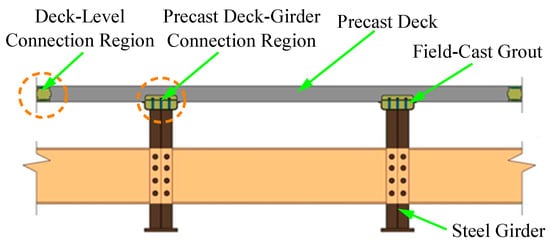
Figure 1.
Prefabricated composite girder with girder-to-deck connections.
2. Design of Railway Bridge Prototype Using Prefabricated Composite Girders with Different Girder-to-Deck Connections
The railway bridge prototype of prefabricated composite girders with girder-to-deck connections was designed to facilitate future application enhancement of off-site construction. As indicated in Figure 2 and Figure 3, the prototype bridge was designed with a bridge width of 13.46 m and a 49.8 m span. The bridge carries 2 traffic lanes and 2 pedestrian lanes. The superstructure includes 2 prefabricated composite girders. The deck is 325–400 mm thick. The steel girders have a height of 3.8 m and a distance between girders of 6.2 m. Figure 4 presents the detail of the members of the railway bridge prototype.
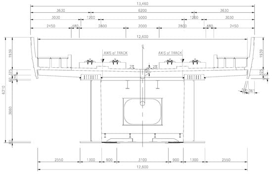
Figure 2.
Cross-sectional view of the railway bridge prototype.
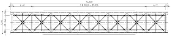
Figure 3.
Plan sectional view of the railway bridge prototype.
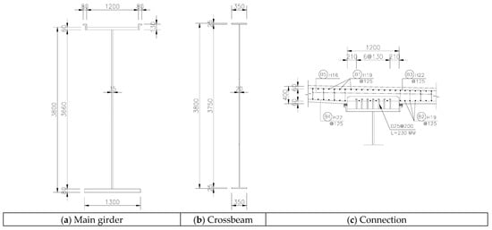
Figure 4.
The detail of the members.
The structural steel used for the steel girders, stiffeners, and crossbeams conforms to HSB380. The reinforcement has a yield stress of 400 MPa. The ultimate tensile strength and yield strength of the stud connector are 420 MPa and 380 MPa, respectively. The compressive strength of the grout and precast concrete is 60 MPa and 35 MPa, respectively.
This prototype was used to develop the cases of prefabricated composite girders with different girder-to-deck connections in this study. Four cases were generated by adding loop reinforcement, changing the stud connector height and precast deck configuration from the prototype bridge, as indicated in Figure 5. The reinforcement spacing of each case is investigated in Section 3. It should be noted that the reinforcement spacing mentioned in this study is the spacing between reinforcement connectors connecting the precast deck and the grout.
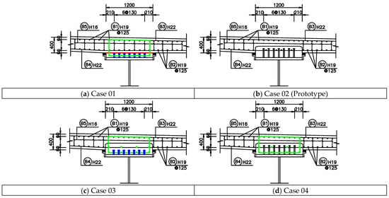
Figure 5.
Connection detail of cases (the green, blue, and red details in the developed cases are the details that are added or changed from the prototype case).
3. Design of Different Girder-to-Deck Interface Connections
3.1. Calculation Theory of Interface Shear Transfer
In this study, the shear interfaces of the girder-to-deck interface connection are mainly calculated according to AASHTO LRFD bridge design specifications, 9th Edition (2020) [12].
According to Article 5.7.4.3 in the AASHTO LRFD, the design of shear interfaces shall satisfy the criteria:
where Vui is the factored interface shear force, vui is the factored interface shear stress, Vni (vni) is the nominal interface shear resistance, Vri (vri) is the factored interface shear resistance, ϕ is the resistance factor for shear.
Vui ≤ Vri = ϕVni
vui ≤ vri = ϕvni
vui ≤ vri = ϕvni
According to Article C5.7.4.5 in the AASHTO LRFD, the factored interface shear force per unit length (Vui):
where Vu is the factored vertical shear force on the beam element, dv is the distance between the centroid of the bottom flange and the mid-thickness of the slab.
By dividing the Vui by the width of the interface (bvi), the factored interface shear stress (vui) is determined utilizing the equation:
According to the plastic approach adopted by the AASHTO LRFD, the interface shear force between the point of maximum positive moment and the point of zero moment shall be taken as:
where As is the area of the steel girder, Fy is the yield strength of the steel, Ac is the effective area of the concrete deck, fc′ is the compressive strength of concrete.
By dividing the Vui by the area of the interface, the interface shear stress (vui) is determined utilizing the equation:
where Vui is the interface shear force, Ls is the length of the shear span, bvi the width of the interface.
The AASHTO LRFD (Article 5.7.4.3) suggests equations to compute the nominal interface shear resistance across any given plane at: a potential or existing crack; an interface between different materials; an interface between two concrete segments cast at different times; or the interface between different elements of the cross section. The nominal interface shear resistance (Vni) shall be taken as:
where μ is the friction factor (see Table 1), c is the cohesion factor (see Table 1), Acv is the area of concrete section resisting shear transfer, Avf is the area of shear reinforcement crossing the interface, fy is the reinforcement yield stress, Pc is the permanent net compressive force normal to the shear plane, fc′ is the compressive strength of concrete, K1 is the fraction of concrete strength available to resist interface shear (see Table 1), K2 is the limiting interface shear strength (see Table 1).

Table 1.
Coefficients for different interface types.
By dividing the values in Equation (6) by the interface area (Acv), the nominal interface shear resistance (vni) can be calculated from the equation:
where N is the permanent net compressive stress (=Pc/Acv). Ρ is the interface shear reinforcement ratio (=Avf/Acv).
In addition, according to Article 5.7.4.2 in the AASHTO LRFD, the cross-sectional area of the interface shear reinforcement (Avf) crossing the interface area (Acv) shall satisfy:
3.2. The Different Girder-to-Deck Interface Connections
Figure 6 illustrates the cross section of prefabricated composite girders with different girder-to-deck connections proposed in this study. There are four cases proposed. These cases differ in details of reinforcement, stud connector, and precast deck structure. Since the connection with multi-step casting concrete, the design of the girder-to-deck interface connection is different from that of a conventional composite connection. The design of the girder-to-deck interface connection strongly influences the structural performance of the prefabricated composite girder. It includes three critical interface types: (1) interface of monolithic grout, (2) interface between the field-cast haunch and the precast deck, and (3) interface between the field-cast haunch and the steel girder. This study focused on interface types (1) and (2) because of the diversity of these interface types with different girder-to-deck interface connections. It is necessary for in-depth analysis to ensure accurate calculation of connection details. Consequently, the structural performance of the prefabricated composite girder is ensured. The shear planes (interfaces) of different girder-to-deck interface connections are shown in Figure 7. In Figure 7, the mechanical connector is the reinforcement or stud connector. It should be noted that these are only potential shear planes. Based on the evaluation of the number of reinforcements crossing the shear plane at a cross section and shear plane type (monolithic shear plane or cold-joint shear plane), the shear planes governing the reinforcement detail of cases 01, 02, and 04 are usually shear planes 1.1, 2.1, and 4.1, respectively. Particularly for Case 03, it is necessary to have a comparison between shear planes 3.1, 3.2, and 3.3. Therefore, not all shear planes are calculated in Section 3.3. The design of the interface type (3) is similar to the design for a conventional composite girder, with reference to Article 6.10.10 of the AASHTO LRFD.
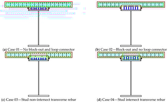
Figure 6.
Prefabricated composite girders with different girder-to-deck connections.
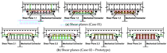
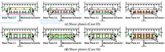
Figure 7.
Potential shear planes of different girder-to-deck interface connections.
3.3. The Reinforcement Spacing of Cases
The details of the girder-to-deck interface connections are different so the reinforcement spacing of the cases varies and it is investigated in this section. From the calculation theory of interface shear transfer presented in Section 3.1, the reinforcement-spacing demand is calculated in the following order:
- (1)
- Computing the interface shear-resistance demand (Vni-dem):
The interface shear-resistance demand is calculated from the force so that the flexural moment strength of the girder reaches the plastic moment. The plastic moment of 266,935 kNm is determined from the equation proposed by Diep et al. [11]. Since the 4-point bending analysis is applied, the vertical shear force (Vu) is 16,477.5 kN. Then, the interface shear-resistance demand can be determined according to Equation (2) with additional consideration of the resistance factor (ϕ = 0.9).
- (2)
- Computing the reinforcement area demand (Avf-dem):
The reinforcement-area demand is determined as the larger value of: area of reinforcement based on the interface shear-resistance demand (using Equation (6)) and minimum area of reinforcement (using Equation (8)).
- (3)
- Computing the reinforcement-spacing demand (Svf):
From the reinforcement-area demand and the details of the girder-to-deck interface connections, the reinforcement-spacing demand is determined.
The calculation results of the reinforcement-spacing demand are summarized in Table 2. From the results of the reinforcement-spacing demand, the reinforcement spacing selected for cases 01 to 04 is 100 mm, 125 mm, 225 mm, and 275 mm, respectively. These reinforcement spacings are used for finite-element analysis models presented in Section 4. It can be seen that the reinforcement-spacing demand increased gradually from Case 01 to Case 04. However, the reinforcement-spacing demand can be adjusted for specific design purposes based on influential parameters. The parameters affecting the reinforcement-spacing demand are investigated in Section 5.
Table 2.
Summary of calculation of reinforcement-spacing demand.
For more convenience in determining the reinforcement spacing, a design aid chart was generated utilizing the equation for estimating the interface shear resistance, which controls the connection design. To demonstrate the use of the design aid chart, the interface shear-resistance demand of 4500 N/mm of the prototype bridge is used to determine the different alternatives in terms of reinforcement spacing for cases, as shown in Figure 8. From Figure 8, it can be seen that the reinforcement spacing for cases 01 to 04 is 100 mm, 125 mm, 225 mm, and 275 mm, respectively, to satisfy interface shear criteria. With the same reinforcement spacing, the interface shear resistance increases gradually from Case 01 to Case 04.
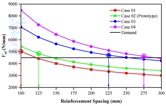
Figure 8.
Design chart for nominal interface shear resistance.
Note that with the design of the reinforcement spacing as above, the interface shear criteria were satisfied for all cases. In addition, the interface shear-resistance demand of 4554.32 N/mm determined from Equation (4) is only slightly greater than that of 4487.33 N/mm determined from Equation (2) so the interface shear criteria were also satisfied when calculated according to the plastic approach, as illustrated in Table 3.
Table 3.
Check of interface shear criteria according to the plastic approach.
4. Numerical Investigation
4.1. General
In this study, numerical investigation using ABAQUS (2020) [13] was conducted to determine the flexural moment strength of prefabricated composite girders with different girder-to-deck connections. Only half of the prefabricated composite girder was modeled because of its symmetry.
4.2. Finite-Element Type and Mesh
Figure 9 shows the model of the prefabricated composite girder. The prefabricated composite girder includes five members: concrete deck, steel girder, connection grout, rebar, and shear connector. The reinforcement arrangement of the cases is shown in Figure 10. To model the concrete deck, connection grout, and shear connector parts, the solid element C3D8R was utilized. To model the rebar part, the truss element T3D2 was used. The shell element S4R was utilized to model the steel girder part. To reduce the analysis time, the appropriate mesh size was applied. The optimum mesh size was determined by a convergence study. The results show that the mesh size was 200 mm. In particular, because the shear connector is small in dimension, it has a mesh size of (10 to 15) mm. Therefore, the number of finite elements in the generated mesh was 297,243 for a typical case (Case 02). Figure 11 shows the finite-element type and mesh of the prefabricated composite girder.
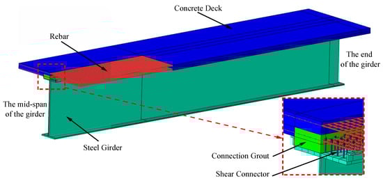
Figure 9.
Model of the prefabricated composite girder.
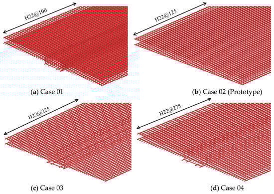
Figure 10.
The reinforcement arrangement of cases.
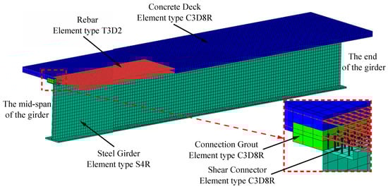
Figure 11.
Finite-element type and mesh.
4.3. Constraint Conditions and Interaction
The interaction between members was considered using proper constraints and interactions, as shown in Figure 12. The shear connector was divided into two parts: the lower part was connected to the upper flange of the steel girder by a tie constraint, and an embedded constraint was used to connect the upper part to the connection grout. The grout–steel interaction was defined utilizing surface-to-surface contact, hard contact was adopted in the normal direction of the interface, a penalty function was adopted in the tangential direction of the interface, and the friction factor was 0.3 [14]. Reinforcements were placed inside the connection grout and concrete deck, and were connected to them by the embedded constraint.
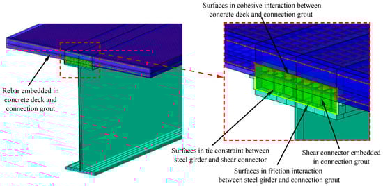
Figure 12.
Constraint and interaction surfaces.
For these analytical models, the contact surfaces between the connection grout and the precast concrete deck play a key role. In the present approach, a surface-based cohesive behavior initially defines a traction-separation model, followed by the initiation and evolution of damage, which is used to model the cohesive effect at the interface. Therefore, the contact surface is assumed to indicate linear elastic behavior in terms of a constitutive matrix that relates tractions to separations by:
For the uncoupled traction-separation type, tn, ts, and tt represent normal, shear, and tangential tractions (along the global Z-axis, X-axis, and Y-axis, respectively), while δn, δs, and δt denote the corresponding separations. Subsequently, damage modeling describes degradation and failure of the bond at the interface, where the damage initiation describes the beginning of degradation of the cohesive response at each contact point, while the damage evolution refers to the rate at which the cohesive stiffness is degraded once the corresponding initiation criterion is reached.
For the damage initiation at the interface, the quadratic traction criterion is considered among some criteria available in the ABAQUS:
An effective separation (δm) is considered to describe the damage evolution under a combination of normal and other separations across the interface:
In general, uncoupled stiffness coefficients (Knn, Kss, Ktt), peak values of traction (t0n, t0s, t0t), and an effective separation at complete failure (δfm) are utilized to simulate cohesive failure in the contact surfaces. In this study, these parameters are selected so that the flexural moment strength of the girder reaches the nominal flexural resistance (Mn). The nominal flexural resistance is determined from the equation proposed by Diep et al. [11]. The ability of the flexural moment strength of the girder to reach the nominal flexural resistance was verified in studies of Diep et al. [11] and Choi et al. [15]. As a result, the values of these parameters are as follows: Knn = Kss = Ktt = 15, t0n = t0s = t0t = 5, and δfm = 4.
4.4. Loading and Boundary Conditions
A typical 4-point bending test analysis was conducted to determine the flexural moment strength at the loading point of prefabricated composite girders with different girder-to-deck connections. Only half of the prefabricated composite girder was modeled because of its symmetry. The distance between the loading point and the end of the girder is 17,000 mm. The supporting point of the prefabricated composite girder was restrained against the translational displacements in the X and Y directions. The surface at the mid-span of the prefabricated composite girder applied the symmetric boundary condition due to its symmetry so that the rotational displacements Rx and Ry and the translational displacement UZ of all nodes on the surface were restrained. Figure 13 shows the loading and boundary conditions.
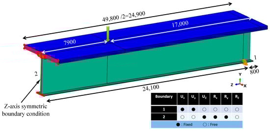
Figure 13.
Loading and boundary conditions.
4.5. Analysis Method
The Riks method available in ABAQUS was utilized to estimate the flexural moment strength of the prefabricated composite girder. This is an implicit load-control method that is normally used in nonlinear static analysis.
4.6. Material Model
Figure 14a indicates the stress–strain relationship for precast concrete material. For the compressive properties of precast concrete, the stress–strain curve including three segments proposed by Hognestad [16] was adopted. The first segment of the stress–strain curve is assumed to be in the linear elastic region to 0.3(fc′) [17]. The initial Young’s modulus (Ec) is computed using Equation (12). The second segment of the stress–strain curve is the nonlinear parabolic part. The variation of this segment can be determined by Equation (13). The third segment of the stress–strain curve is the linear decreasing segment, and varies according to Equation (14).
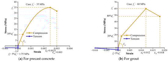
Figure 14.
Stress–strain relationship for materials.
For the precast concrete in tension, before the concrete cracks, the tensile stress is assumed to increase linearly, but then decreases linearly. The maximum tensile strength of concrete (ft) is assumed to be 5 % of the compressive strength of concrete (fc′) [18].
To model the precast concrete material, the Concrete Damage Plasticity model available in the ABAQUS material library was used. This model assumes a non-associated potential plastic flow, where recommendation values (default) of the ordinary concrete material in the ABAQUS are taken: ψ = 30°, K = 0.667, ε = 0.1, fb0/fc0 = 1.16.
For the compressive properties of grout, the stress–strain relationship proposed by Kaushik et al. [19] was adopted. Kaushik et al. [19] found that the strain of grout at the maximum compressive strength (ε0) is taken as (0.010 to 0.013), and its ultimate strain (εcu) is taken as (0.017 to 0.019). The elastic modulus of grout (Eg) is calculated using Equation (15). Thus, in this analysis, ultimate strain (εcu) and the strain at the maximum compressive strength (ε0) of grout are assumed to be (0.018 and 0.012), respectively. The ultimate stress and limit stress of the linear elastic range are assumed to be (80 and 30) % of the compressive strength of grout, respectively. A tri-linear model was used. For the tensile properties of grout, the variation rule of tensile stress of grout is assumed to be similar to that of precast concrete. Figure 14b indicates the stress–strain relationship of the grout material. To model the grout material, the Concrete Damage Plasticity model was also used.
The elastic-perfectly plastic curve was applied to the reinforcement and shear connector steel. The real stress–strain curve was applied to structural steel HSB380.
4.7. Results
Figure 15a provides a comparison of the flexural moment strength from the FEA of cases 01, 03, and 04 with Case 02 (Prototype). The difference was 0.35%, 0.04%, and 0.24%, respectively. Therefore, these cases had a negligible difference in flexural moment strength; the largest difference was in Case 01 due to a change of precast deck detail. In all cases, the flexural moment strength is greater than the nominal flexural resistance, so the flexural performance was ensured. The flexural failure-mode shape for a typical case is illustrated in Figure 16. As can be seen, almost the whole section of the prefabricated steel girder yielded, except for the locations around the plastic neutral axis, and the flexural performance was ensured as mentioned.
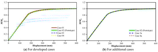
Figure 15.
The moment ratio-displacement curve for cases.
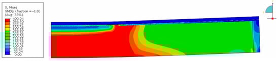
Figure 16.
The flexural failure-mode shape for a typical case.
Additional finite-element analysis models were performed to evaluate the influence of the degree of interaction between the connection grout and precast concrete deck on the behavior of the prefabricated composite girder. These models were created by reducing the reinforcement spacing for cases 03 and 04 to 150 mm, named cases 3a and 4a, to increase the degree of interaction for the prefabricated composite girder. Figure 15b compares the FEA results based on the degree of interaction. The difference of flexural moment strength for cases 3a and 4a compared to Case 02 was 0.14% and 0.35%, respectively. Therefore, the increase of flexural moment strength was not significant. As a result, the influence of the degree of interaction between the connection grout and precast concrete deck was negligible, since the condition of the full shear connection was satisfied for the prefabricated composite girder and reinforcement spacing should be optimally designed through the theory of interface shear transfer.
5. Parametric Study
In addition to the two comparison criteria of reinforcement spacing and flexural moment strength above, the following criteria should also be considered: (1) the fabrication of the precast deck: the fabrication of the precast deck in Case 01 is the easiest and most convenient. (2) grout volume: the grout volume in Case 01 is the smallest. In contrast, the other cases have greater grout volume. (3) the dependence of the reinforcement connector on the reinforcement of the slab: the reinforcement connector is independent of the slab reinforcement in Case 01 so the arrangement of the reinforcement connector is the easiest in this case. In other cases, the slab reinforcement is also the reinforcement connector (Case 02), or is a part that contributes to the connection (Case 03, Case 04).
From the above comparison of the cases, Case 01 has the most advantages, the only disadvantage being that it has the smallest reinforcement-spacing demand. If this drawback is overcome, this is the most optimum case. Therefore, parameters influencing the reinforcement-spacing demand should be considered and investigated in this section. Influential parameters include: area of section resisting shear transfer (Acv) (related to interface width (bv)), vertical shear force (Vu), distance between the centroid of the bottom flange and the mid-thickness of the slab (dv) (related to height of composite girder (h)), and diameter of reinforcement (Dreinf).
Case 01 was used for investigation. From Case 01, the initial values of the influential parameters mentioned above are adjusted so that the reinforcement-spacing demand increases and is approximately equal (≈150 mm). These cases are named cases 1.1 to 1.4 (because there are four influential parameters), as shown in Table 4. Therefore, in specific cases, design parameters can be selected to arrange more reasonable reinforcement spacing.
Table 4.
Parameters affecting the reinforcement-spacing demand.
The influential parameter is also verified through numerical investigation. Table 5 indicates the content of the parametric studies. To be able to compare the cases with each other, only the parameters that do not affect the calculated flexural moment strength are investigated through numerical simulation. Based on the calculation results in Table 4, the FEA of two additional cases was conducted to evaluate the influence of the parameters (diameter and spacing of reinforcement) and compare with Case 01. From Case 01 (the reinforcement spacing was 100 mm), the reinforcement spacing was changed to 150 mm in Case 1a. The reinforcement spacing was also changed to 150 mm in Case 1b but in addition, the reinforcement diameter of 25 mm was used to replace that of 22 mm in Case 01 (ensure the full shear connection). Figure 17 shows the reinforcement arrangement for the cases of the parametric study.
Table 5.
Content of the parametric studies.
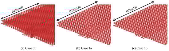
Figure 17.
The reinforcement arrangement for cases of the parametric study.
The moment ratio-displacement curve for cases of parametric study is indicated in Figure 18. The FEA results agree well with the calculation theory. In Case 1a, the flexural moment strength did not reach the nominal flexural resistance because the full shear connection was not satisfied in this case. The flexural moment strength in Case 1b was approximate to that in Case 01. These two cases had different spacing and diameter of reinforcement but both satisfied full shear connection. Therefore, it proves that the reinforcement spacing can be adjusted based on the influential parameters while still ensuring the connection performance.
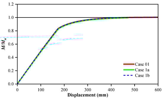
Figure 18.
The moment ratio-displacement curve for cases of the parametric study.
Figure 19 shows the Mises stress of reinforcement connectors at failure-mode shape for Case 1a. From Figure 19, reinforcement connectors were observed to obtain the yield stress at the shear plane 1.1 so the flexural moment strength did not reach the nominal flexural resistance in this case. The FEA result agrees well with the calculation theory.
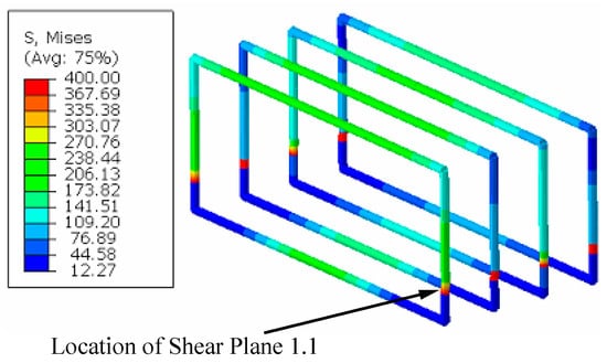
Figure 19.
Mises stress of reinforcement connectors at failure-mode shape (Case 1a).
6. Conclusions
In this study, prefabricated composite girders with different girder-to-deck connections were proposed, and the structural performance of prefabricated composite girders was investigated. From the results, the conclusions below were drawn:
- (1)
- Several different types of girder-to-deck interface connections for the prefabricated composite girder, which have a sufficient structural performance compared to the AASHTO LRFD requirements, can be proposed by rationally arranging shear reinforcement at the connection detail based on the application of interface shear transfer theory. Along with that is the change of stud connector height and precast deck structure.
- (2)
- The details of the girder-to-deck interface connections are different so the reinforcement spacing of the cases varies. The spacing between bars of reinforcement connecting the precast deck and the grout which controls the connection design increased gradually from Case 01 to Case 04. However, the reinforcement spacing can be adjusted for specific design purposes based on influential parameters. With such design of reinforcement spacing, all developed cases satisfied the interface shear criteria according to both conventional and plastic approaches.
- (3)
- There was no significant difference in flexural moment strength between the investigated cases. In all cases, the flexural performance was ensured. The influence of the degree of interaction between the connection grout and precast concrete deck was negligible, since the condition of the full shear connection was satisfied in all cases for the prefabricated composite girder and reinforcement spacing should be optimally designed through the theory of interface shear transfer.
- (4)
- The AASHTO LRFD provision of interface shear transfer is applied to concrete-to-concrete interfaces. However, the FEA results are in good agreement with the calculation results according to the AASHTO LRFD. It demonstrates that the AASHTO LRFD provision of interface shear transfer is applicable to grout-connection interfaces, in particular, girder-to-deck interface connections of prefabricated composite girders. A Push-off test needs to be carried out for verification.
- (5)
- All developed cases can be used for railway bridges. If the influential parameters can be adjusted to arrange the reasonable reinforcement spacing, Case 01 is the most optimum case that should be considered. In contrast, other cases should be considered.
Author Contributions
Conceptualization, B.H.C.; methodology, B.H.C., H.T.D. and J.M.; software, H.T.D.; validation, B.H.C.; formal analysis, H.T.D. and B.H.C.; investigation, H.T.D., B.H.C. and J.M.; resources, B.H.C.; data curation, B.H.C. and J.M.; writing—original draft preparation, H.T.D.; writing—review and editing, B.H.C. and J.M.; visualization, J.M.; supervision, B.H.C.; project administration, B.H.C.; funding acquisition, B.H.C. All authors have read and agreed to the published version of the manuscript.
Funding
This research was conducted with the support of the “National R&D Project for Smart Construction Technology (Grant No.22 SMIP-A158708-03)”, funded by the Korea Agency for Infrastructure Technology Advancement under the Ministry of Land, Infrastructure and Transport, and managed by the Korea Expressway Corporation.
Institutional Review Board Statement
Not applicable.
Informed Consent Statement
Not applicable.
Data Availability Statement
Not applicable.
Conflicts of Interest
The authors declare no conflict of interest.
References
- Haber, Z.; Graybeal, B. Performance of Grouted Connections for Prefabricated Bridge Deck Elements; Report no. FHWA-HIF-19-003; FHWA—Federal Highway Administration: Washington, DC, USA, 2018.
- Biswas, M. Precast Bridge Deck Design Systems. PCI J. 1986, 31, 40–94. [Google Scholar] [CrossRef]
- Tawadrous, R.; Morcous, G. Interface shear resistance of clustered shear connectors for precast concrete bridge deck systems. Eng. Struct. 2018, 160, 195–211. [Google Scholar] [CrossRef]
- Zhu, P.; Ma, Z.J. Selection of Durable Closure Pour Materials for Accelerated Bridge Construction. J. Bridge Eng. 2010, 15, 695–704. [Google Scholar] [CrossRef]
- Yi, G.S.; Kim, J.K.; Choi, B.H. Inelastic Moment-Rotation Response of 690 MPa Grade Steel I-Section Girders. Int. J. Steel Struct. 2017, 17, 1669–1680. [Google Scholar] [CrossRef]
- Santos, P.M.D.; Júlio, E.N.B.S.; Silva, V.D. Correlation between Concrete-to-Concrete Bond Strength and the Roughness of the Substrate Surface. Constr. Build. Mater. 2007, 21, 1688–1695. [Google Scholar] [CrossRef]
- Graybeal, B. Bond of Field-Cast Grouts to Precast Concrete Elements; Report no. FHWA-HRT-16-081; FHWA—Federal Highway Administration: Washington, DC, USA, 2017.
- Ovuoba, B.; Prinz, G.S. Headed shear stud fatigue demands in composite bridge girders having varied stud pitch, girder depth, and span length. J. Bridge Eng. 2018, 23, 04018085. [Google Scholar] [CrossRef]
- Badie, S.S.; Girgis, A.; Tadros, M.K.; Nguyen, N.T. Relaxing the stud spacing limit for full-depth precast concrete deck panels supported on steel girders (phase I). J. Bridge Eng. 2010, 15, 482–492. [Google Scholar] [CrossRef]
- Graybeal, B. Ultra-High Performance Concrete Composite Connections for Precast Concrete Bridge Decks; Report no. FHWA-HRT-12-041; FHWA—Federal Highway Administration: Washington, DC, USA, 2012.
- Diep, H.T.; Jang, M.; Moon, J.; Choi, B.H. Numerical Analysis on Plastic Moment Capacity of Prefabricated Steel Girders with Injection Channel Connections. Int. J. Steel Struct. 2022, 22, 1722–1733. [Google Scholar] [CrossRef]
- AASHTO. LRFD Bridge Design Specifications, 9th ed.; AASHTO: Washington, DC, USA, 2020. [Google Scholar]
- SIMULIA. ABAQUS Analysis User’s Guide; SIMULIA: Providence, RI, USA, 2020. [Google Scholar]
- Baltay, P.; Gjelsvik, A. Coefficient of friction for steel on concrete at high normal stress. J. Mater. Civ. Eng. 1990, 2, 46–49. [Google Scholar] [CrossRef]
- Choi, B.H.; Diep, H.T.; Moon, J. Flexural Performance of Prefabricated Composite Girders along with Precast Deck-to-Girder Continuous Connections. Int. J. Steel Struct. 2023. submitted. [Google Scholar]
- Hognestad, E. A Study of Combined Bending and Axial Load in Reinforced Concrete Members, Bulletin 399; University of Illinois Engineering Experiment Station: Urbana, IL, USA, 1951. [Google Scholar]
- Bangash, M.Y.H. Concrete and Concrete Structures: Numerical Modeling and Application. Appl. Sci. 1989, 22, 22054809. [Google Scholar]
- Chen, W.F. Plasticity in Reinforced Concrete; McGraw-Hill: New York, NY, USA, 1982. [Google Scholar]
- Kaushik, H.B.; Rai, D.C.; Jain, S.K. Stress-Strain Characteristic of Clay Brick Masonry under Uniaxial Compression. J. Mater. Civ. Eng. 2007, 19, 728–739. [Google Scholar] [CrossRef]


Disclaimer/Publisher’s Note: The statements, opinions and data contained in all publications are solely those of the individual author(s) and contributor(s) and not of MDPI and/or the editor(s). MDPI and/or the editor(s) disclaim responsibility for any injury to people or property resulting from any ideas, methods, instructions or products referred to in the content. |
© 2023 by the authors. Licensee MDPI, Basel, Switzerland. This article is an open access article distributed under the terms and conditions of the Creative Commons Attribution (CC BY) license (https://creativecommons.org/licenses/by/4.0/).