
Durable Nanofiber-Based Membrane with Efficient and Consistent Performance for Oil/Saltwater Separation
Abstract
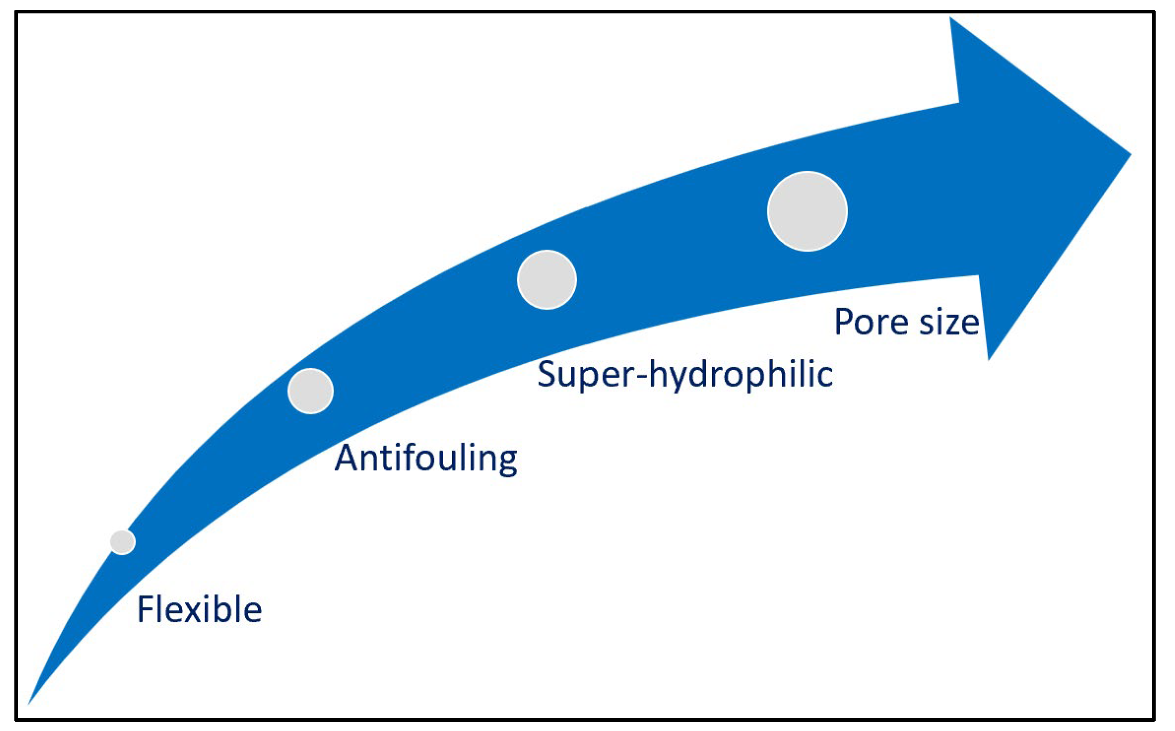
:1. Introduction
- The produced water refers to the water that is returned to the surface through a well borehole. The quantity of produced water is increasing with increased volumes of global oil/gas production. This project will examine the feasibility of the synthesized membrane to treat produced water.
- Oil spills can occur in the sea and cause a negative impact on the ocean and marine life. The major human activities that cause oil spills are land drainage and waste disposal, offshore drilling, and spills from ships or tankers. These practices form a saline oily wastewater that requires a treatment process. This work will examine the feasibility of the synthesized membrane to treat saline oily water.
2. Materials and Methods
2.1. Materials
2.2. Emulsion Preparation
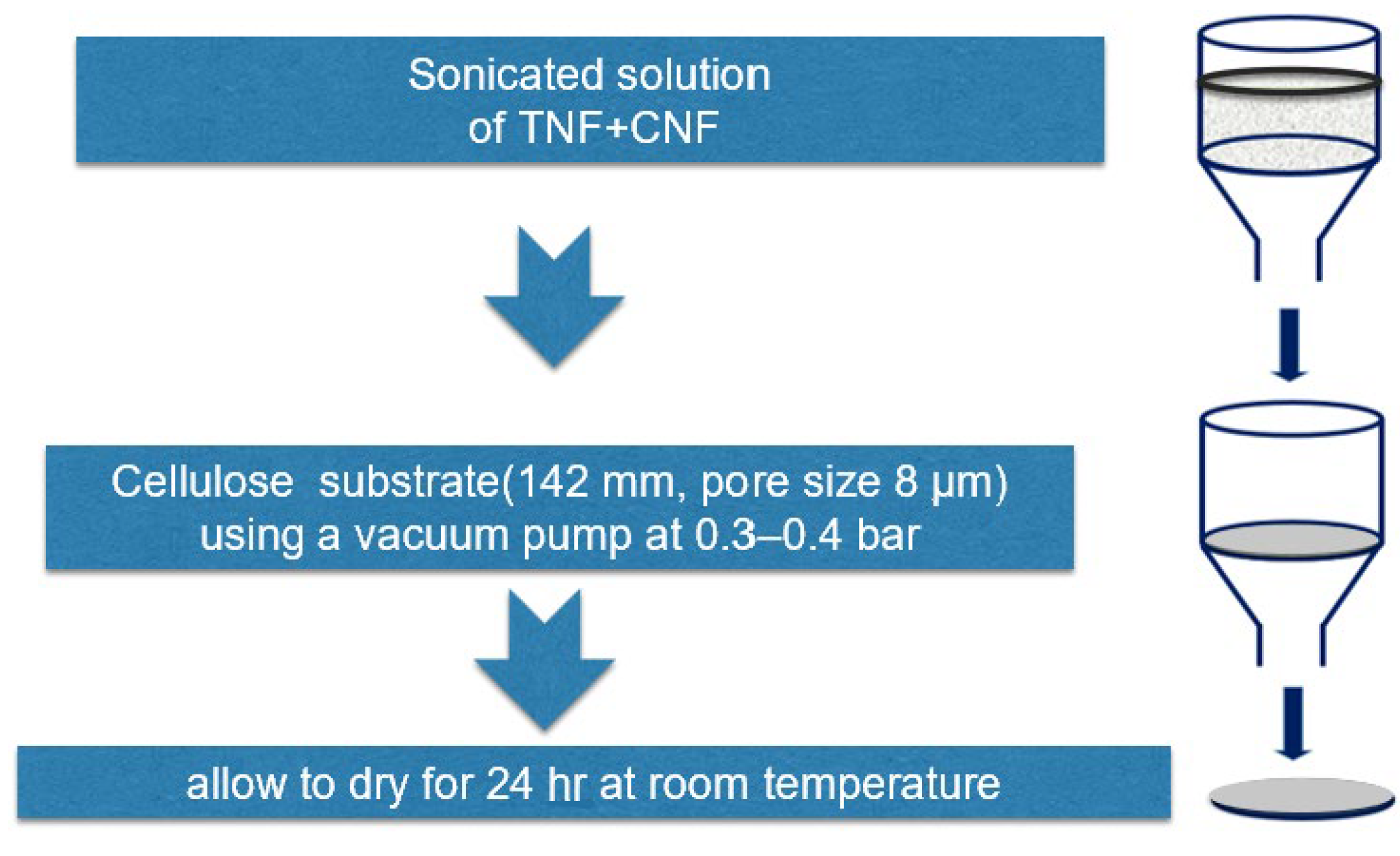
2.3. Membrane Fabrication
2.3.1. Titanium Nanofiber Synthesis
2.3.2. Carbon Nanofiber Solution
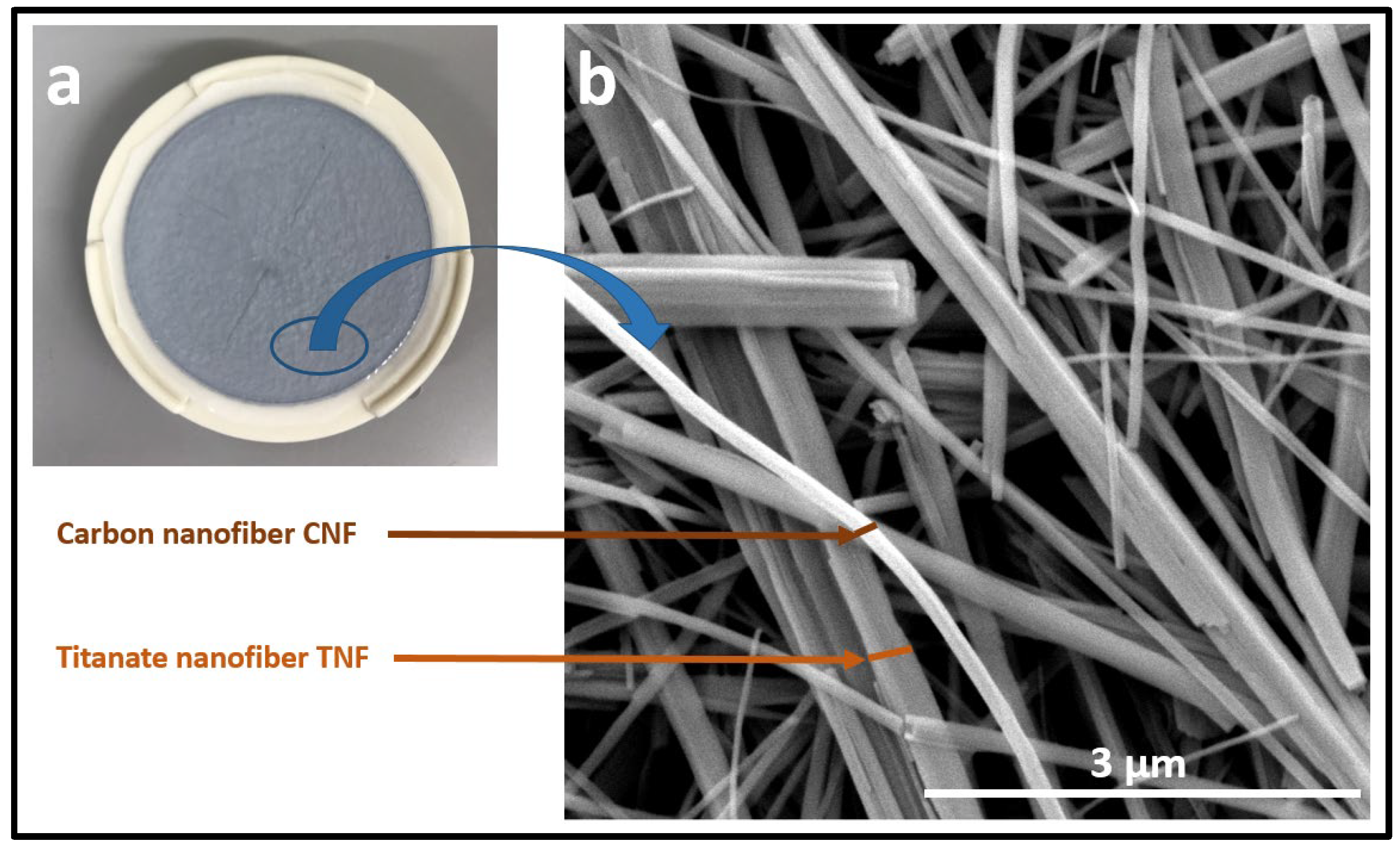
2.3.3. Membrane Preparation
2.4. Instruments and Characterization
2.5. Performance Test
2.6. Calculation Procedure
2.6.1. Flux Calculation
2.6.2. Oil Rejection
2.6.3. Oil Rejection
3. Results and Discussion
3.1. SEM
3.2. XRD and EDS
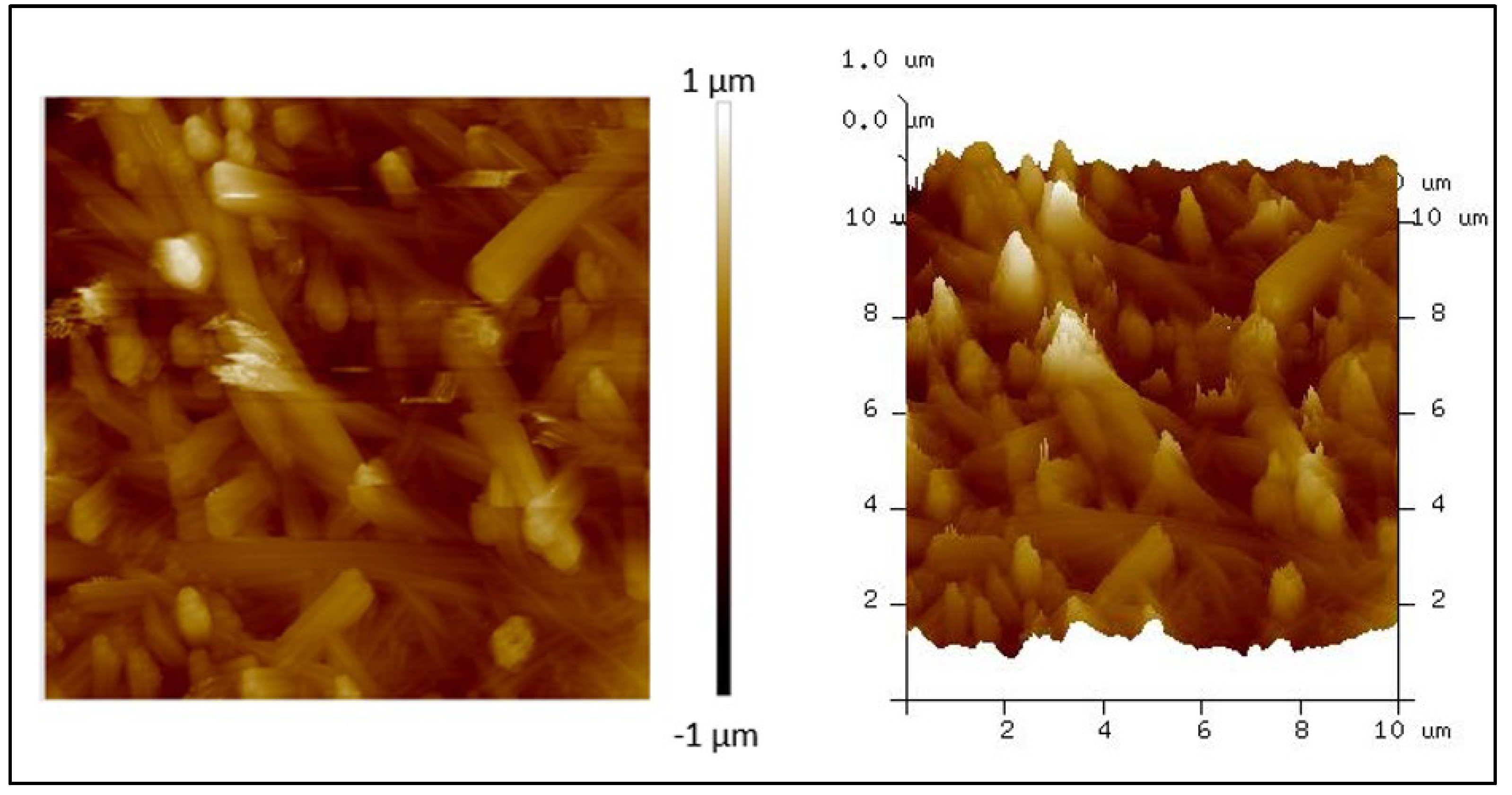
3.3. AFM
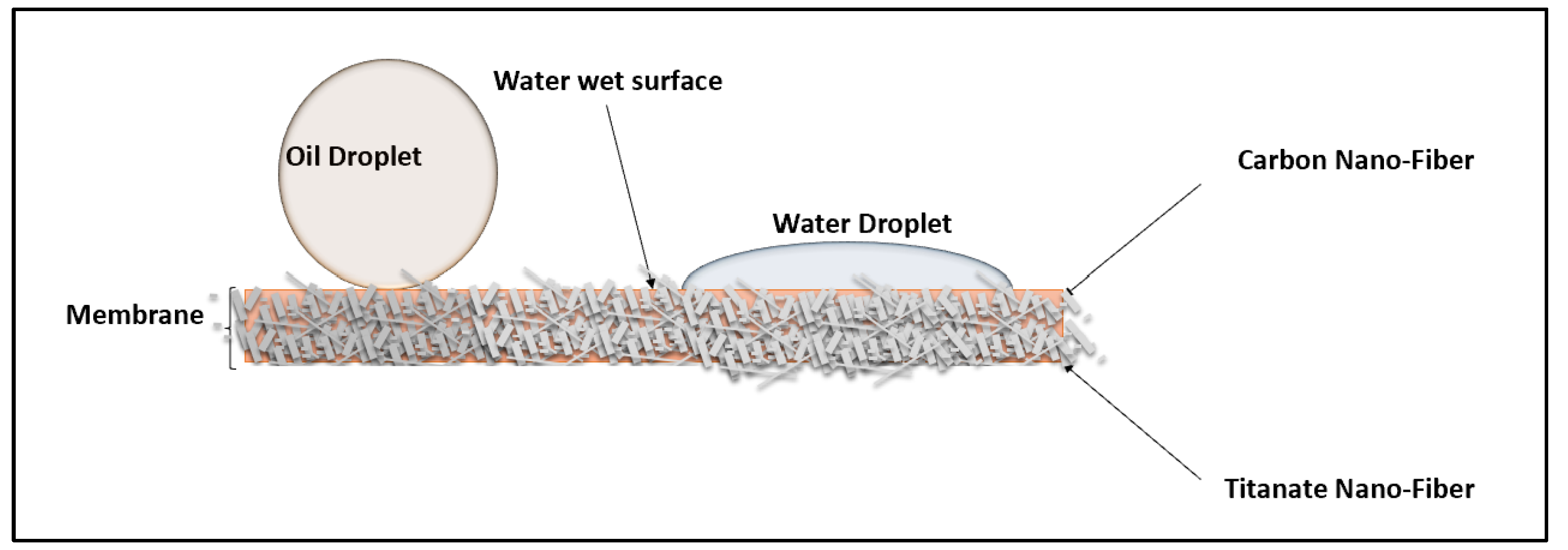
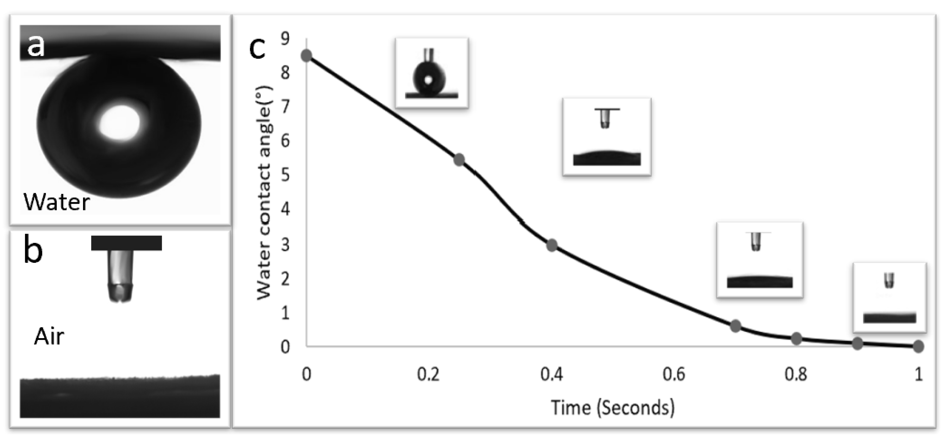
3.4. Contact Angles for Membrane Wettability
3.5. Performance Tests of the Membranes for the Removal of Emulsified Oil
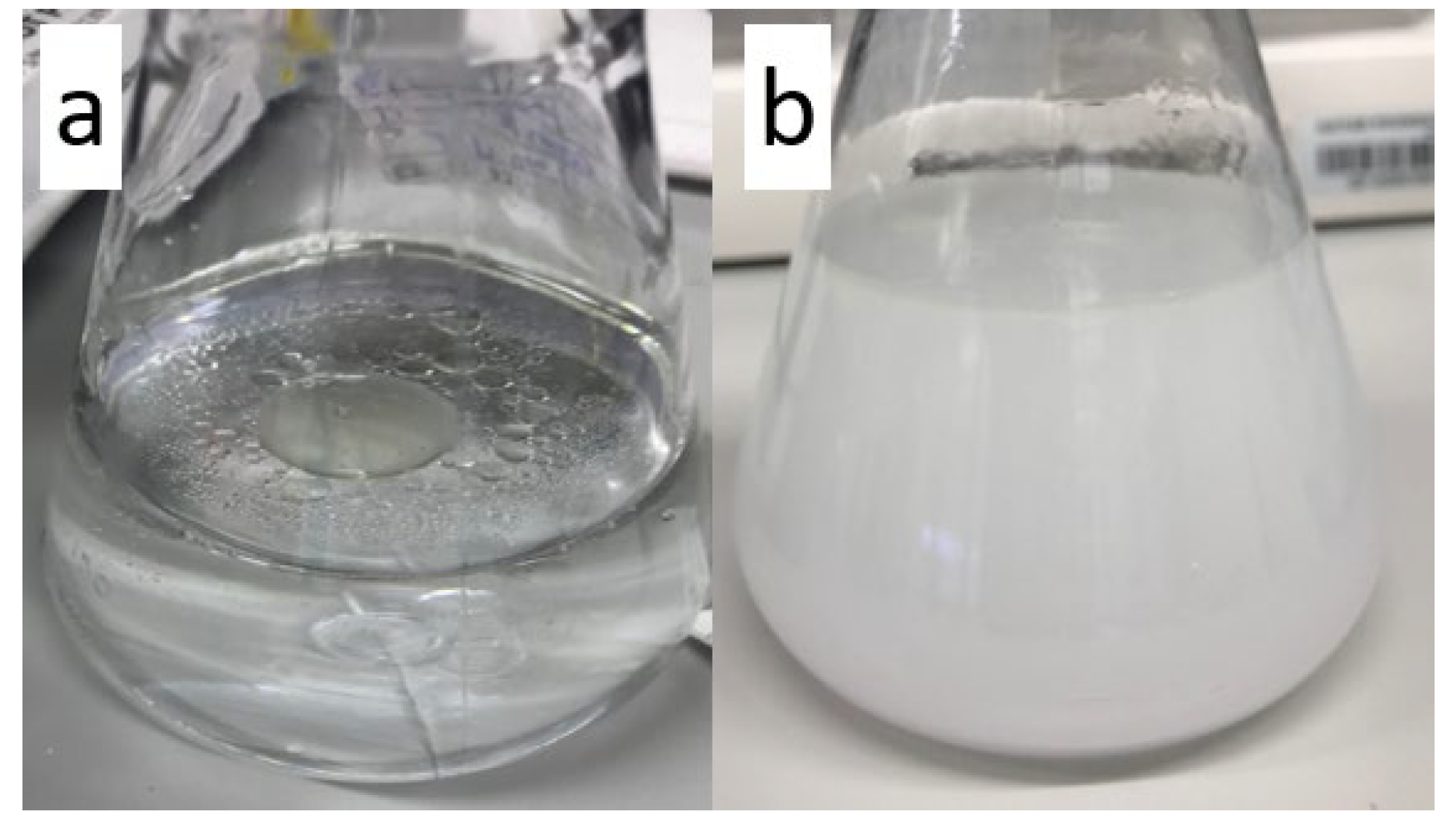
3.5.1. Oil on Water Emulsion
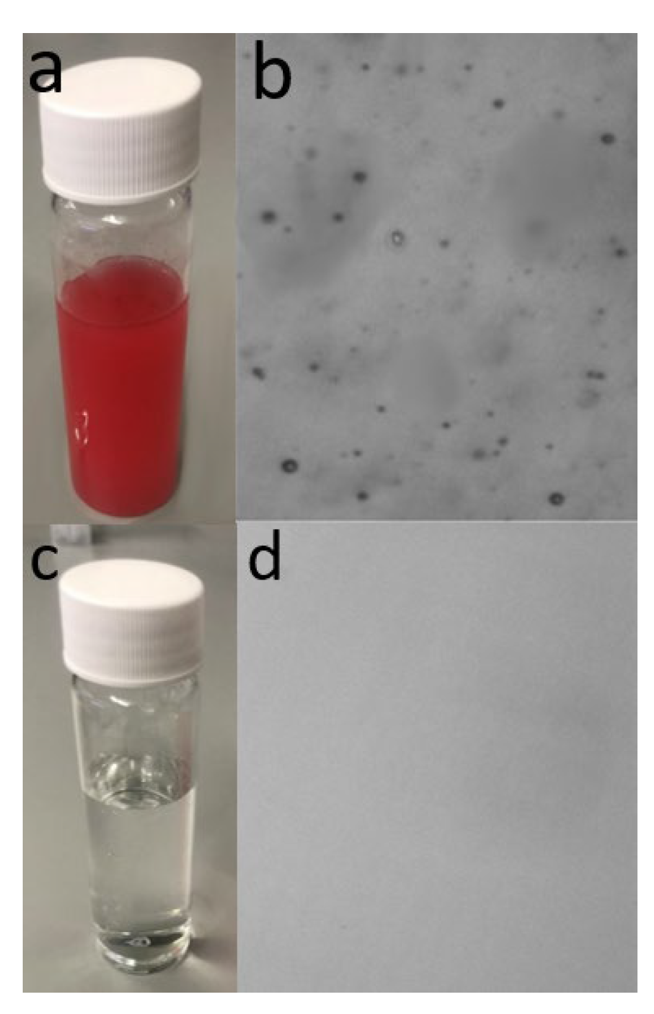
3.5.2. Image Characterization of the Water/Oil Solutions before and after Treatment
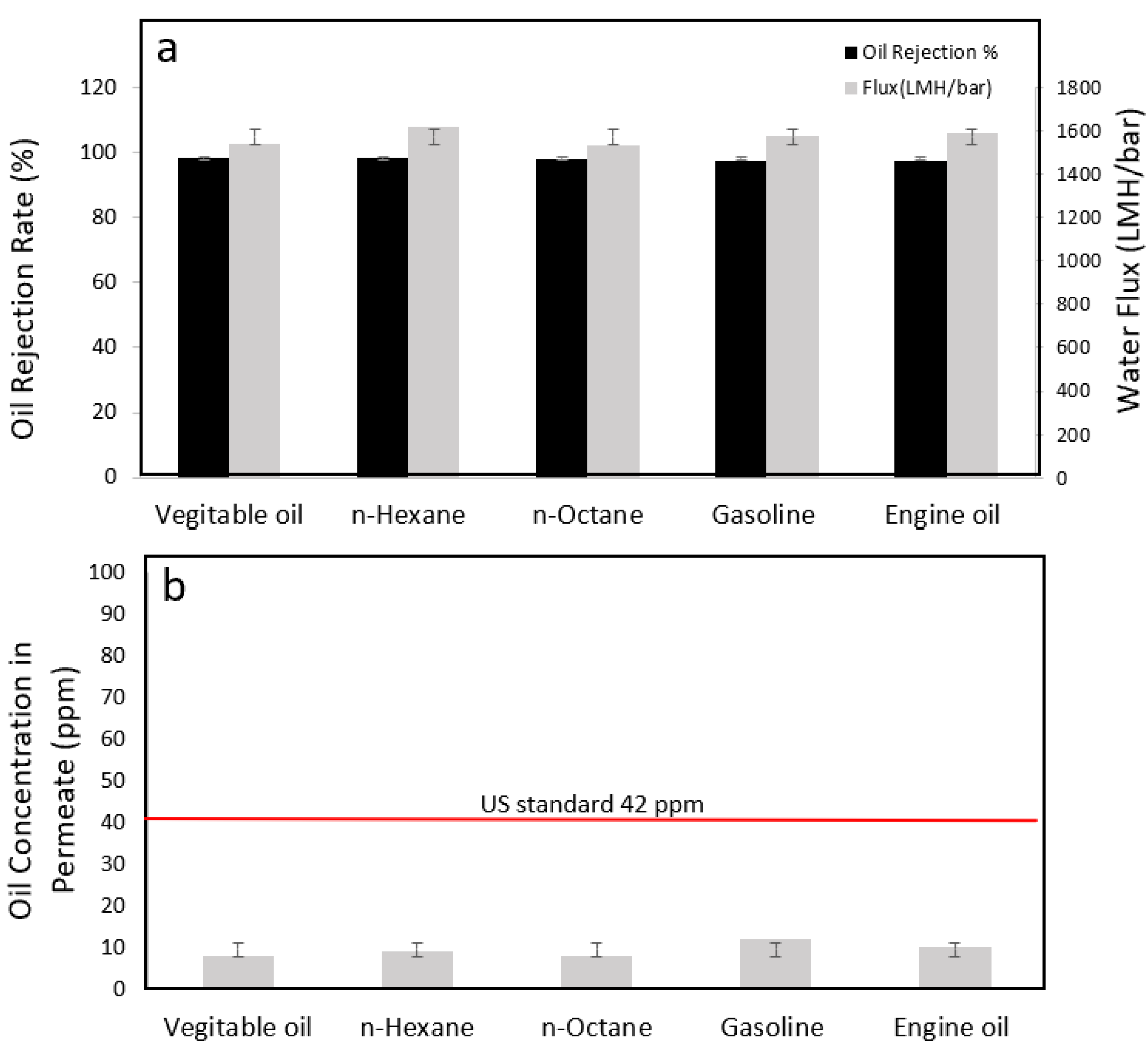
3.5.3. Performance Tests with Different Oils
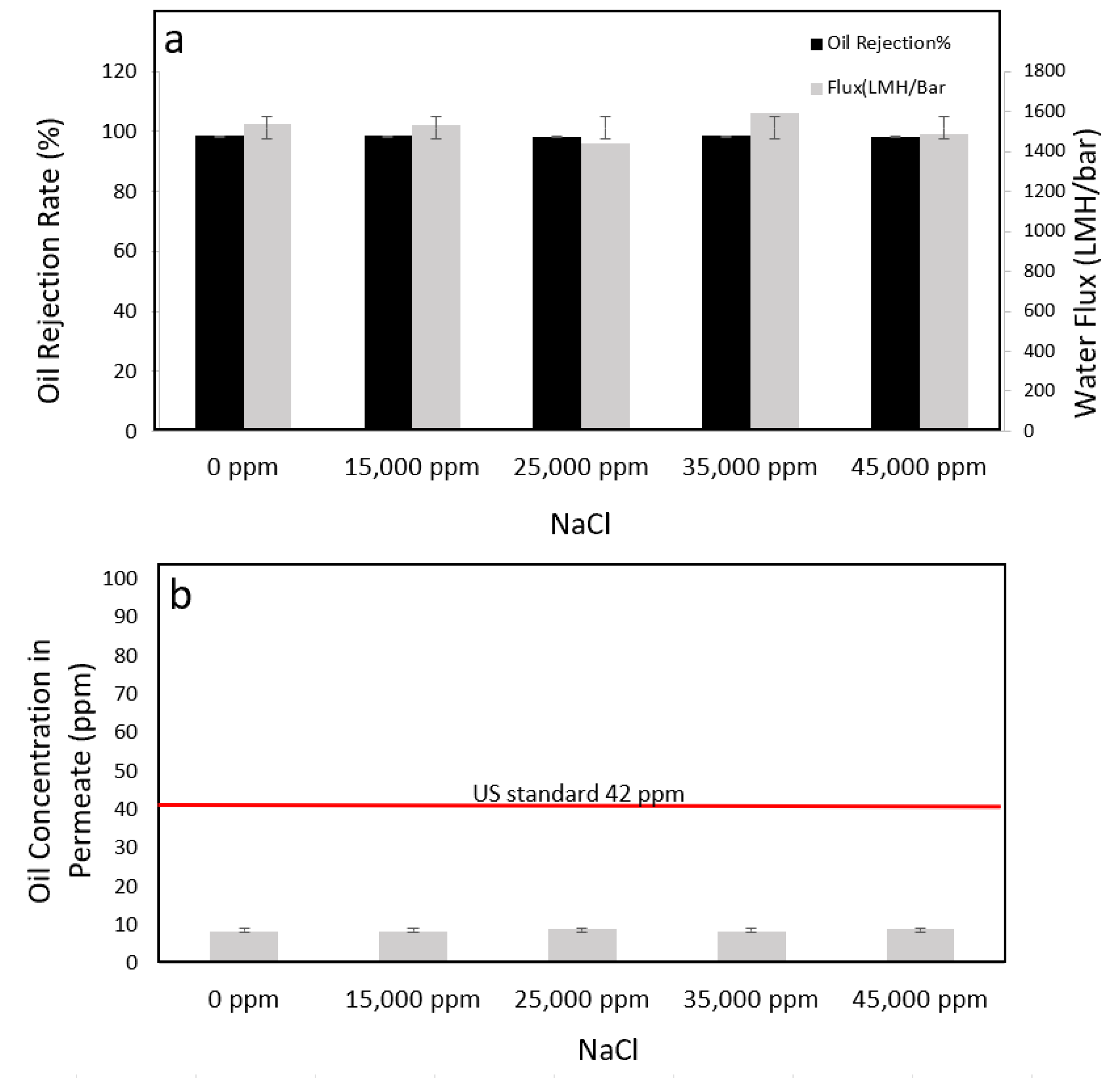
3.5.4. Performance Tests with Different Salty Environments
3.5.5. Reusability Test for the Membranes
4. Conclusions
Supplementary Materials
Author Contributions
Funding
Informed Consent Statement
Acknowledgments
Conflicts of Interest
References
- Bolto, B.; Zhang, J.; Wu, X.; Xie, Z. A review on current development of membranes for oil removal from wastewaters. Membranes 2020, 10, 65. [Google Scholar] [CrossRef] [PubMed] [Green Version]
- 40 CFR, Chapter 1, Environmental Protection Agency 435.1, USA, 2019. Available online: https://www.ecfr.gov/current/title-40/chapter-I/subchapter-N/part-435/subpart-A (accessed on 1 February 2023).
- Baig, U.; Waheed, A. An efficient and simple strategy for fabricating a polypyrrole decorated ceramic-polymeric porous membrane for purification of a variety of oily wastewater streams. Environ. Res. 2023, 219, 114959. [Google Scholar] [CrossRef]
- Gul, A.; Hruza, J.; Yalcinkaya, F. Fouling and chemical cleaning of microfiltration membranes: A mini-review. Polymers 2021, 13, 846. [Google Scholar] [CrossRef]
- Obaid, M.; Kang, Y.; Wang, S.; Yoon, M.-H.; Kim, C.-M.; Song, J.-H.; Kim, I.S. Fabrication of highly permeable thin-film nanocomposite forward osmosis membranes via the design of novel freestanding robust nanofiber substrates. J. Mater. Chem. A 2018, 6, 11700–11713. [Google Scholar] [CrossRef]
- Tummons, E.; Han, Q.; Tanudjaja, H.J.; Hejase, C.A.; Chew, J.W.; Tarabara, V.V. Membrane fouling by emulsified oil: A review. Sep. Purif. Technol. 2020, 248, 116919. [Google Scholar] [CrossRef]
- Dmitrieva, E.S.; Anokhina, T.S.; Novitsky, E.G.; Volkov, V.V.; Borisov, I.L.; Volkov, A.V. Polymeric Membranes for Oil-Water Separation: A Review. Polymers 2022, 14, 980. [Google Scholar] [CrossRef] [PubMed]
- Yong, J.; Yang, Q.; Hou, X.; Chen, F. Emerging Separation Applications of Surface Superwettability. Nanomaterials 2022, 12, 688. [Google Scholar] [CrossRef]
- Matindi, C.N.; Kadanyo, S.; Liu, G.; Hu, M.; Hu, Y.; Cui, Z.; Ma, X.; Yan, F.; He, B.; Li, J. Hydrophilic polyethyleneimine-TiO2 hybrid layer on polyethersulfone/sulfonated polysulfone blend membrane with antifouling characteristics for the effective separation of oil-in-water emulsions. J. Water Process Eng. 2022, 49, 102982. [Google Scholar] [CrossRef]
- Fen, L.; Zhang, Z.; Mai, Z.; Ma, Y.; Liu, B.; Jiang, L.; Zhu, D. A super-hydrophobic and super-oleophilic coating mesh film for the separation of oil and water. Angew. Chem. Int. Ed. 2004, 43, 2012–2014. [Google Scholar] [CrossRef]
- Kusworo, T.D.; Qudratun; Utomo, D.P. Performance evaluation of double stage process using nano hybrid PES/SiO2-PES membrane and PES/ZnO-PES membranes for oily waste water treatment to clean water. J. Environ. Chem. Eng. 2017, 5, 6077–6086. [Google Scholar] [CrossRef]
- Omalanga, L.; Iyuke, S.; Nkazi, B.; Biyela, P. Impact of Carbon Nanotubes on the Polymeric Membrane for Oil—Water Separation. Int. J. Nanosci. Nanotechnol. 2019, 15, 99–115. Available online: https://www.ijnnonline.net/article_35420.html (accessed on 1 April 2023).
- Xue, Z.; Wang, S.; Lin, L.; Chen, L.; Liu, M.; Feng, L.; Jiang, L. A novel superhydrophilic and underwater superoleophobic hydrogel-coated mesh for oil/water separation. Adv. Mater. 2011, 23, 4270–4273. [Google Scholar] [CrossRef] [PubMed]
- Zhang, Q.; Liu, N.; Wei, Y.; Feng, L. Facile fabrication of hydrogel coated membrane for controllable and selective oil-in-water emulsion separation. Soft Matter 2018, 14, 2649–2654. [Google Scholar] [CrossRef] [PubMed]
- Sun, H.; Zhang, Y.; Sadam, H.; Ma, J.; Bai, Y.; Shen, X.; Kim, J.-K.; Shao, L. Novel mussel-inspired zwitterionic hydrophilic polymer to boost membrane water-treatment performance. J. Membr. Sci. 2019, 582, 1–8. [Google Scholar] [CrossRef]
- Sakai, T. Surfactant-free emulsions. Curr. Opin. Colloid Interface Sci. 2008, 13, 228–235. [Google Scholar] [CrossRef]
- Fard, A.K.; Bukenhoudt, A.; Jacobs, M.; McKay, G.; Atieh, M.A. Novel hybrid ceramic/carbon membrane for oil removal. J. Membr. Sci. 2018, 559, 42–53. [Google Scholar] [CrossRef]
- Jung, S.M.; Jung, H.Y.; Fang, W.; Dresselhaus, M.S.; Kong, J. A Facile Methodology for the Production of In Situ Inorganic Nanowire Hydrogels/Aerogels. Nano Lett. 2014, 14, 1810–1817. [Google Scholar] [CrossRef]
- Sun, W.; Chen, T.; Chen, C.; Li, J. A study on membrane morphology by digital image processing. J. Membr. Sci. 2007, 305, 93–102. [Google Scholar] [CrossRef]
- Kim, J.-H.; Lee, J.-H.; Kim, J.-Y.; Kim, S.S. Synthesis of aligned TiO2 nanofibers using electrospinning. Appl. Sci. 2018, 8, 309. [Google Scholar] [CrossRef] [Green Version]
- Sikhwivhilu, L.M.; Mpelane, S.; Moloto, N.; Ray, S.S. Hydrothermal Synthesis of TiO2 Nanotubes: Microwave Heating Versus Conventional Heating. Nanostruct. Mater. Nanotechnol. IV Ceram. Eng. Sci. Proc. 2010, 31, 45–49. [Google Scholar]
- Yoon, S.H.; ElShorafa, R.; Katbeh, M.; Han, D.S.; Jeong, H.W.; Park, H.; Abdel-Wahab, A. Effect of shape-driven intrinsic surface defects on photocatalytic activities of titanium dioxide in environmental application. Appl. Surf. Sci. 2017, 423, 71–77. [Google Scholar] [CrossRef]
- Rajasekhar, T.; Trinadh, M.; Babu, P.V.; Sainath, A.V.S.; Reddy, A.V.R. Oil-water emulsion separation using ultrafiltration membranes based on novel blends of poly(vinylidene fluoride) and amphiphilic tri-block copolymer containing carboxylic acid functional group. J. Membr. Sci. 2015, 481, 82–93. [Google Scholar] [CrossRef]
- Barambu, N.U.; Bilad, M.R.; Wibisono, Y.; Jaafar, J.; Mahlia, T.M.I.; Khan, A.L. Membrane surface patterning as a fouling mitigation strategy in liquid filtration: A review. Polymers 2019, 11, 1687. [Google Scholar] [CrossRef] [Green Version]
- Vrijenhoek, E.M.; Hong, S.; Elimelech, M. Influence of membrane surface properties on initial rate of colloidal fouling of reverse osmosis and nanofiltration membranes. J. Memb. Sci. 2001, 188, 115–128. [Google Scholar] [CrossRef]
- Elimelech, M.; Zhu, X.; Childress, A.E.; Hong, S. Role of membrane surface morphology in colloidal fouling of cellulose acetate and composite aromatic polyamide reverse osmosis membranes. J. Memb. Sci. 1997, 127, 101–109. [Google Scholar] [CrossRef]
- Liu, Y.; Coppens, M.O. Cell Membrane-Inspired Graphene Nanomesh Membrane for Fast Separation of Oil-in-Water Emulsions. Adv. Funct. Mater. 2022, 32, 2200199. [Google Scholar] [CrossRef]
- Elshorafa, R.; Saththasivam, J.; Liu, Z.; Ahzi, S. Efficient oil/saltwater separation using a highly permeable and fouling-resistant all-inorganic nanocomposite membrane. Environ. Sci. Pollut. Res. 2020, 27, 15488–15497. [Google Scholar] [CrossRef] [Green Version]
- Hashim, I.A.; Aisueni, F.; Ogunlude, P.; Ramalan, M.; Ogoun, E.; Gobina, E. Using contact angle measurements for determination of the surface free energy of ceramic membranes. TechConnect Briefs 2022, 44, 5–8. [Google Scholar]
- Mansourizadeh, A.; Azad, A.J. Preparation of blend polyethersulfone/cellulose acetate/polyethylene glycolasymmetric membranes for oil–water separation. J. Polym. Res. 2014, 21, 375. [Google Scholar] [CrossRef]
- Chakrabarty, B.; Ghoshal, A.K.; Purkait, M.K. Purkait, Ultrafiltration of stable oil-in-water emulsion by polysulfone membrane. J. Membr. Sci. 2008, 325, 427–437. [Google Scholar] [CrossRef]
- Vatai, G.N.; Krstić, D.M.; Koris, A.K.; Gáspár, I.L.; Tekic, M.N. Ultrafiltration of oil-in-water emulsion: Comparison of ceramic and polymeric membranes. Desalination Water Treat. 2009, 3, 162–168. [Google Scholar] [CrossRef]


| Total Area of Sample µm2 | Total Area of Pores µm2 | % of Pores Area |
|---|---|---|
| 46.455 | 9.956 | 21.4 |
| Mean Size (µm) | d10 (µm) | d50 (µm) | d90 (µm) |
|---|---|---|---|
| 3.35 | 2.04 | 2.83 | 5.72 |
| Membrane | Rejection Rate (%) | Flux (LMH/Bar) | Operation Pressure (KPa) | Reference |
|---|---|---|---|---|
| PES/CA 1 | 88 | 6.73 | 400 | [30] |
| Polysulfone | >90 | 1605 | 103.4 | [31] |
| Ceramic ZrO2 | >90 | <100 | >100 | [32] |
| TNF/CNF on cellulose paper | >99 | 1520 | 30 | Current paper |
Disclaimer/Publisher’s Note: The statements, opinions and data contained in all publications are solely those of the individual author(s) and contributor(s) and not of MDPI and/or the editor(s). MDPI and/or the editor(s) disclaim responsibility for any injury to people or property resulting from any ideas, methods, instructions or products referred to in the content. |
© 2023 by the authors. Licensee MDPI, Basel, Switzerland. This article is an open access article distributed under the terms and conditions of the Creative Commons Attribution (CC BY) license (https://creativecommons.org/licenses/by/4.0/).
Share and Cite
ElShorafa, R.; Liu, Z.; Ahzi, S. Durable Nanofiber-Based Membrane with Efficient and Consistent Performance for Oil/Saltwater Separation. Appl. Sci. 2023, 13, 6792. https://doi.org/10.3390/app13116792
ElShorafa R, Liu Z, Ahzi S. Durable Nanofiber-Based Membrane with Efficient and Consistent Performance for Oil/Saltwater Separation. Applied Sciences. 2023; 13(11):6792. https://doi.org/10.3390/app13116792
Chicago/Turabian StyleElShorafa, Rand, Zhaoyang Liu, and Said Ahzi. 2023. "Durable Nanofiber-Based Membrane with Efficient and Consistent Performance for Oil/Saltwater Separation" Applied Sciences 13, no. 11: 6792. https://doi.org/10.3390/app13116792