Article

Factors Associated with the Proximity of the Incisive Canal to the Maxillary Central Incisor

Department of Orthodontics, School of Dentistry, Kanagawa Dental University, Yokosuka 238-8580, Japan
*
Author to whom correspondence should be addressed.
Appl. Sci. 2023, 13(12), 6899; https://doi.org/10.3390/app13126899
Submission received: 6 May 2023 / Revised: 2 June 2023 / Accepted: 6 June 2023 / Published: 7 June 2023
(This article belongs to the Section Applied Dentistry and Oral Sciences)

Abstract

:
The position of the maxillary central incisors (MCIs) is an important factor in treatment planning since it is related to esthetics and physiological function. This study aimed to evaluate maxillofacial morphology related to the proximity of the MCI to the incisive canal (IC) using cone-beam computed tomography (CBCT). In 157 patients, the distance between the MCI and IC was measured using CBCT images, and the maxillofacial morphology was measured using cephalograms. The relationship between age, sex, and cephalometric analysis was subsequently investigated using stepwise multiple regression analysis, with the distance between the MCI root apex and IC as the objective variable, and age, sex, and cephalometric variables as explanatory variables. The results demonstrated significant associations between the distance separating point A and the pterygomaxillary fissure projected on the palatal plane (B = 0.092, p < 0.01), the maxillary central incisal edge to the Frankfort horizontal plane (B = −0.058, p < 0.01), and the mandibular plane (B = −0.036, p = 0.031). Age and sex showed no association with the distance between the IC and MCI. Particular attention should be paid to the proximity of the tooth root to the IC in patients with short anteroposterior diameters of the maxilla and an anterior labial tilt of the dolichofacial type.

1. Introduction

Maxillary incisors contribute to esthetics and physiological functions such as speech and mastication [1,2,3]. Thus, the position of the maxillary incisors is crucial in orthodontic diagnosis and treatment planning. The anterior portion of the maxilla, also known as the incisor alveolar bone, may present abnormal growth with various malformations, such as prognathism and deep bite [4]; proclined maxillary incisors are considered the most frequent type of malocclusion [5].
The ideal position of the maxillary incisors is determined based on various soft and hard tissue criteria, and patients with maxillary prognathism typically undergo maximum anterior retraction for improving their facial and esthetic profile [6,7,8,9]. Meanwhile, the clinical guideline based on the “enlargement of discrepancy” recommends that the maximum amount of maxillary incisor retraction by orthodontic intervention alone should be 7 mm [10,11]. Orthodontic tooth movement within the biological limits is desirable for successful treatment results with long-term stability as excessive movement can cause fenestration and root resorption from the alveolar bone [12,13].
One of the anatomically limiting factors in maxillary incisor retraction is the palatal cortical plate [14,15,16,17,18,19,20]. Moreover, the incisive canal (IC) should be considered for interventions that involve retraction of the maxillary central incisor (MCI). The IC is an anatomical structure located in the median plane of the maxillary processus palatinus, posterior to the root of the MCI, surrounded by thick cortical bone [21]. It is an elongated structure connecting the oral and nasal cavities through the incisive and nasopalatine foramina, encompassing the nasopalatine vessels and maxillary branch of the trigeminal nerve and maxillary artery [22,23,24,25,26,27,28]. Because the IC is located between the palatine cortical plate and MCI, the presence and morphometric properties of the IC should also be included as essential components of the treatment planning procedure [29,30].
Maxillary incisor retraction is presumed to influence MCI invasion into the IC, and the thrust into the IC or contact between the peri-cortical bone of the IC and tooth root induces root resorption [7,9,20,30,31,32,33]. According to radiographic examination, the IC is surrounded by a radiopaque cortex, shown as a well-defined radiopaque area [28]. Cone-beam computed tomography (CBCT) provides more detailed information about the IC, including morphology and morphometric properties [9,34]. Computed tomography (CT) scans [22], micro-CT images [23], or high-resolution magnetic resonance imaging [35] have been used to analyze the macro- and microanatomy of the maxillary anterior region. In this study, the anterior maxillary region was evaluated using CBCT for tomographic imaging. CBCT administers a lower radiation dose to the patient compared to conventional CT scans and has many other advantages [36].
Because avoiding contact between the MCI and IC, and even intrusion into the IC, is vital for maxillary anterior tooth movement planning, the distance assessment between the IC and MCI has received clinical attention in the planning of orthodontic treatment involving MCI retraction [6,7,8,9,20,29,30,34]. Cephalometric radiographs, which are two-dimensional X-ray examinations, cannot accurately assess the relationship between the IC and MCI owing to the overlapping of the facial structures [37]. However, they can assess craniofacial morphology and anterior tooth positioning, which are most frequently requested as part of orthodontic planning and orthognathic surgery. Furthermore, as maxillofacial morphology is closely related to jaw growth and the development of malocclusion [38], assessment of the relationship to craniofacial morphology is important for orthodontic treatment planning, in addition to structural evaluation of the IC and MCI.
The relationship between vertical and horizontal intermaxillary relationships, maxillary bone morphology, and proximity between the IC and MCI is yet to be fully elucidated. Costa et al. [39] examined the relationship between vertical and anteroposterior skeletal patterns and sex, and the proximity of the IC and MCI, and reported a minor effect of the factors. However, they used the relative anterior–posterior relationship of the maxilla and mandible as an indicator when assessing the anteroposterior skeletal patterns. Since the IC is encapsulated in the maxilla, absolute evaluation of the maxillary morphology and size may provide useful insights into the anatomic relationship between the IC and MCI.
Therefore, this study aimed to explore the relationship between the maxillofacial morphology, including vertical and anteroposterior skeletal patterns, maxillary bone size and anteroposterior position, anteroposterior position and angle of the MCI, and the proximity of the IC and MCI.

2. Materials and Methods

2.1. Participants

This study included 157 Japanese patients (54 males, 104 females; mean age: 27.1 ± 9.5 years) aged 18–58 years at the Department of Orthodontics, Kanagawa Dental University Hospital. The sample sizes were calculated using G*Power software (ver. 3.1.9.6; Heinrich-Heine-Universität Düsseldorf, Düsseldorf, Germany). The study was exploratory, with an effect size of 0.15 and an explanatory variable of 9. The sample size required for the study was 114 participants. Patients aged ≥18 years were included, and the exclusion criteria were as follows: (1) nasopalatal lesions, (2) a history of orthodontic treatment, (3) missing or filled maxillary anterior teeth, (4) periodontal disease, and (5) congenital abnormalities (cleft lip and palate).

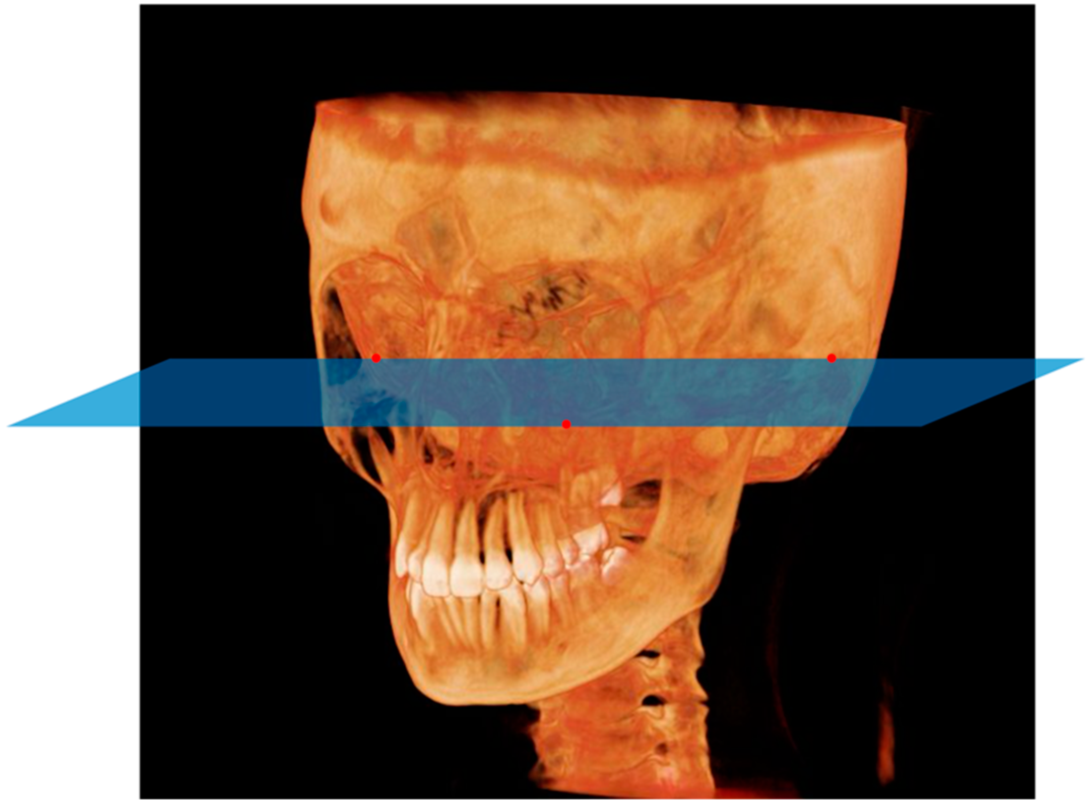
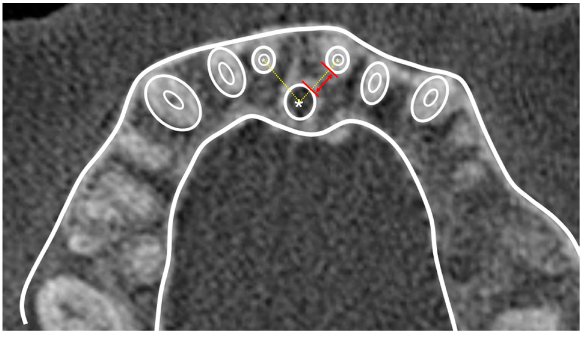
2.2. Data Acquisition and Measurements

CBCT images were acquired using a cone-beam X-ray CT system (KaVo 3D eXam, KaVo, Biberach, Germany). The scan protocols were set at 120 kVp, 5 A, and 0.3-mm voxel size (0.3 × 0.3 × 0.3 mm), and the rotation (scan) time was 17.8 s. The field of view (FOV) was set to 230 × 170 mm. The data were stored in the Digital Imaging and Communications format, subsequently imported into the imaging software, Invivo 6 (Anatomage, San Jose, CA, USA), and reconstructed into three-dimensional (3D) images for further processing and analysis.
The following procedure was used to measure the linear distance between the left and right MCI root apexes and the IC using 3D images. All the dimensional measurements of MCI root apexes and the IC were measured in axial slices parallel to the Frankfort horizontal (FH) plane based on a previous study [20]. The FH plane was defined according to previous studies as the plane passing through the bilateral polion (Po) and left orbita (Or) (Figure 1). The height of the measurement was taken at the level of the MCI root apex (Figure 2). The linear distance between the maxillary central incisor (MCI) root apex and the incisive canal (IC) on each side, defined specifically as the shortest linear distance between the lateral boundary of the MCI root and the lateral boundary of the IC cortical bone, was measured by tracing the center of the MCI root and IC cross-sections, based on the methodologies of previous studies [30] (Figure 3). When the lateral cortical bone boundary of the IC was in contact with the root, the distance between the MCI and the IC was recorded as zero. Left and right averages were used to compare the explanatory variables.
Lateral cephalometric radiographs were used for the anatomical morphology of the maxillofacial region. A Collimator Type R20J (SHIMADZU, Kyoto, Japan) was used for lateral cephalometric imaging and Cephalometrics A to Z ver. 22.0 (YASUNAGA Computer Systems Company, Fukui, Japan) was used for lateral cephalometric analysis. Lateral cephalograms of the patients were acquired when their teeth were in centric occlusion. The lateral cephalometric reference points and lines are listed in Table 1 and illustrated in Figure 4.
This study used two distance and five angle measurements of the cephalometric variables to evaluate the relationship between the MCI and distance to the IC. The seven cephalometric variables are listed in Table 2.
Thirty CBCT images and lateral cephalograms were randomly selected and measured to assess measurer error at 2-week intervals under the same conditions using Dahlberg’s formula [40].
This study was approved by the Ethics Committee of the Kanagawa Dental University (approval numbers 642 and 663). All the CBCT data used in this study were obtained for orthodontic treatment and were not obtained for research purposes. This study was conducted according to the current standards recommended for reporting observational studies in epidemiology, following the Declaration of Helsinki. Consent was obtained from all the patients before the start of treatment.

2.3. Statistical Analysis

The Student’s t-test was used to compare the left–right and sex differences in the distance between the MCI apex and the IC in the two groups. The relationship between the distance separating the MCI root tip and the IC, and age and lateral cephalometric variables, was evaluated using Pearson’s product–moment correlation coefficient. A stepwise multiple regression analysis used the distance between the MCI root apex and the IC as the objective variable, and age, sex, and each lateral cephalometric value as explanatory variables. All the variables’ variance inflation factors (VIF) were confirmed to be <10 for the multicollinearity problem. SPSS Statistics 26 (IBM Corporation, Armonk, NY, USA) was used for statistical analysis, and statistical significance was set at a p-values < 0.05.

3. Results

The measured distance between the MCI apex and IC is shown in Table 3; the average distance between the MCI apex and IC was approximately 3.3 mm. The distance between the MCI apex and IC was significantly smaller on the left side than on the right side (right: 3.43 ± 1.38, left: 3.28 ± 1.37, p < 0.05), and there was no statistically significant difference in the distance between the MCI apex and IC based on sex (male: 3.37 ± 1.30, female: 3.35 ± 1). The results of Pearson’s product–moment correlation coefficient analysis of the relationship between the distance from the MCI apex to the IC and age and lateral cephalometric variables are shown in Table 4. A positive correlation was observed for SNA (r = 0.16, p = 0.04) and A’-Ptm’ (r = 0.23, p < 0.01) and a negative correlation for U1 to FH (r = −0.24, p < 0.01). Table 5 shows the results of the multiple regression analysis, using the distance between the MCI apex and IC as the objective variable, and age, sex, and lateral cephalometric variables as explanatory variables. A positive correlation was observed for A’-Ptm’ (B = 0.092, p < 0.01), U1 to FH (B = −0.058, p < 0.01), and mandibular plane (B = −0.036, p = 0.031). VIF values were <10 for all the explanatory variables, and no evidence of multicollinearity was observed.

4. Discussion

It is important to evaluate and consider the distance between the apex of the MCI and IC to prevent root resorption that may occur when the MCI is in contact with the IC [29,39]. As root contact between the MCI and IC is related to the anatomical morphology around the IC [7,41], the morphological aspects of the MCI and its proximity to the IC have been evaluated using CBCT in many studies [27,42]. The present study investigated the associations between the sagittal and vertical skeletal patterns for the IC, dental axis inclination for the MCI, and patient age and sex.
The FOV and voxel size affect the accuracy of 3D images obtained from a CBCT system [43]; a larger FOV corresponds to a larger voxel size and lower image resolution. The CBCT images used in this study had a FOV of 230 × 170 mm and a voxel size of 0.3 mm. Since the CBCT used in this study was implemented for orthodontic treatment, the maximum FOV was set to cover the entire maxillofacial region. Sang et al. [44] concluded that, when using CBCT to reconstruct and evaluate 3D tooth models for linear, volumetric, and geometric measurements, increasing the voxel resolution from 0.30 to 0.15 mm did not improve accuracy. Furthermore, Gabriela et al. [45] concluded that a voxel size of 0.3 mm was the best protocol with the highest probability ratio values when evaluating external root resorption with the CBCT system for voxel sizes of 0.2, 0.3, and 0.4 mm. Therefore, CBCT images taken with sufficiently accurate voxel size settings were obtained for this study.
Based on the study results, the distance between the apex of the MCI and the IC was approximately 3.3 mm. The distance between the MCI apex and the IC is reportedly more proximal on the right side than on the left side [46]. In contrast, the present study found a significant proximity to the IC on the left side of the MCI compared with the right side.
The limit of upper anterior retraction in orthodontic treatment has long been set at 7 mm [10,11], while measurements of the distance between the MCI and IC using CBCT suggest that it may be less than the conventional guideline [20,41], which is consistent with the findings of the present study. When the position of the IC exceeds 4 mm before and after treatment, the risk of root invasion into the IC and root resorption increases [31]; our study’s results were consistent with this finding. Multivariate analysis demonstrated a negative correlation between the mandibular plane and MCI apex and the distance to the CI.
Considering the vertical skeletal pattern, a shorter face, smaller mandibular angle, and greater muscle strength characterize brachyfacial individuals compared with dolichofacial individuals with longer faces [39]. Several studies have demonstrated that brachyfacial individuals have a greater alveolar bone thickness in the anterior maxillary region [18,47,48,49,50,51,52]. This result is consistent with the distance between the upper central incisor root, and the IC tends to be shorter in dolichofacial than in brachyfacial individuals.
The proximity of the MCI and IC is not affected by the sagittal skeletal pattern [39]; in the present study, the position of the maxilla relative to the mandible, as indicated by the ANB angle, did not affect the proximity of the MCI apex and the IC. Meanwhile, the position of the maxilla relative to the cranium, such as at the SNA landmark, or the anteroposterior size of the maxilla demonstrated an association with the distance to the CI. Thus, the greater the maxillary deficiency an individual exhibits, the more likely it is to cause proximity between the MCI and IC.
Statistically significant sex-related differences have been reported in the anatomical characteristics of the IC, such as length and diameter [53,54], and males have a greater MCI–IC distance than females [42,55]. However, other studies showed that the MCI–IC distance is not significantly affected by sex [39]; the results of the current study were also consistent with this observation. Age has also been shown to significantly influence the IC length. The IC and MCI are proximate to each other in younger individuals [42]. However, one study revealed that the MCI–IC distance has no association with age [56]. In the present study, age did not substantially affect the MCI–IC distance. The influence of age and sex was limited; however, it is important to consider that differences in occlusion and skeletal class can affect anterior tooth recession in orthodontic treatment [39].
Caution should be exercised in cases where maximum anterior retraction is needed to improve soft tissue [57]. In this study, the more labially inclined the maxillary anterior teeth were, the greater the negative correlation with the distance between the root and IC. Because the anatomical morphology of the IC is related to the dental axis inclination of the maxillary anterior teeth and the MCI apex region is more proximal to the IC than other regions [27], we suggest that more attention should be paid to cases warranting lingual inclination of the anterior teeth. Orthodontic treatment in the maxillary central incisor region should always be preceded by careful radiographic analysis owing to the anatomic approximation between the IC and the roots of these teeth. In particular, a thorough and careful analysis of the IC and MCI and positional relationship using CBCT imaging should precede the treatment goals to obtain the best prognosis for orthodontic treatment of the maxillary anterior region. Based on the CBCT-based findings of the present study, the vertical skeletal pattern, especially in the dolichofacial type and the inclination of the MCI, has been associated with the relationship between the MCI–IC distance. Therefore, it provides some insight into clinical practice; especially in the case of camouflage treatment of occlusion in Class II patients of dolichofacial type, special care and precautions should be taken to avoid intrusion into the IC. A 3D evaluation during orthodontic diagnosis and observation of the incisal roots during treatment are useful in preventing possible complications, especially in patients requiring maximum retraction.
Concurrently, changes in the position and inclination of the maxillary incisors result in morphological changes in the maxillary alveolar region [58,59]. Furthermore, the possibility of IC wall remodeling following orthodontic tooth movement has also been reported, with a clear change in the direction and shape of the IC after maxillary anterior tooth movement [20,30,31,41]. Large individual variations in the anatomical morphology of the IC exist [54]. Arnaut et al. [60] reported that different shapes of the sagittal cross-section of the IC, such as funnel, cylindrical, and hourglass shapes, are associated with the distance to the MCI, and they concluded that different shapes could be a regression limiting factor for the MCI.
This study included patients aged ≥18 years; however, it would be worthwhile to quantify these measurements at different time points in growing patients, as orthodontic treatment is routinely performed at younger ages. Further research is required to shed light on host-induced risks such as assessing MCI infiltration into the IC and remodeling of the IC wall following orthodontic tooth movement and considering various parameters, such as broad age, sex, ethnicity, and IC measurements, in addition to the maxillofacial morphology. Further clarification of individual variation could decrease the incidence of orthodontic root resorption and other contingencies associated with orthodontic treatment.

5. Conclusions

The average distance between the MCI apex and the IC was approximately 3.3 mm. Age and sex were not related to the IC–MCI distance. The greater the labial inclination, the more proximally the distance between the MCI apex and the IC became. The shorter the anteroposterior diameter of the maxilla was, the closer the distance between the MCI apex and the IC. Thus, the distance between the MCI apex and the IC was closer in dolichofacial individuals.

Author Contributions

Conceptualization, S.K. and T.Y.; methodology, T.Y.; software, S.K.; validation, S.K. and T.Y.; formal analysis, S.K.; investigation, T.I. and S.K.; resources, T.Y.; data curation, T.I.; writing—original draft preparation, T.I.; writing—review and editing, S.K.; visualization, T.I.; supervision, T.Y.; project administration, T.Y. All authors have read and agreed to the published version of the manuscript.

Funding

This research received no external funding.

Institutional Review Board Statement

The study was approved by the Ethics Committee of the Kanagawa Dental University (approval numbers: 642 [26 February 2020] and 663 [27 April 2020]). This study was conducted according to the current standards recommended for reporting observational studies in epidemiology (STROBE) following the Declaration of Helsinki.

Informed Consent Statement

Informed consent was obtained from all the participants involved in the study.

Data Availability Statement

The data presented in this study are available from the corresponding author upon request.

Conflicts of Interest

The authors declare no conflict of interest.

References

  1. Sarver, D.M. The importance of incisor positioning in the esthetic smile: The smile arc. Am. J. Orthod. Dentofac. Orthop. 2001, 120, 98–111. [Google Scholar] [CrossRef] [PubMed] [Green Version]
  2. Zachrisson, B.U. Esthetic factors involved in anterior tooth display and the smile: Vertical dimension. J. Clin. Orthod. 1998, 32, 432–445. [Google Scholar]
  3. Riedel, R.A. Esthetics and its relation to orthodontic therapy. Angle Orthod. 1950, 20, 168–178. [Google Scholar] [CrossRef] [PubMed]
  4. Barteczko, K.; Jacob, M. A re-evaluation of the premaxillary bone in humans. Anat. Embryol. 2004, 207, 417–437. [Google Scholar] [CrossRef]
  5. Hong, S.Y.; Shin, J.W.; Hong, C.; Chan, V.; Baik, U.B.; Kim, Y.H.; Chae, H.S. Alveolar bone remodeling during maxillary incisor intrusion and retraction. Prog. Orthod. 2019, 20, 47. [Google Scholar] [CrossRef] [PubMed] [Green Version]
  6. Gull, M.A.B.; Maqbool, S.; Mushtaq, M.; Ahmad, A. Evaluation of morphologic features and proximity of incisive canal to the maxillary central incisors using cone beam computed tomography. Angle Orthod. 2018, 17, 46–50. [Google Scholar]
  7. Chung, C.J.; Choi, Y.J.; Kim, K.H. Approximation and contact of the maxillary central incisor roots with the incisive canal after maximum retraction with temporary anchorage devices: Report of 2 patients. Am. J. Orthod. Dentofac. Orthop. 2015, 148, 493–502. [Google Scholar] [CrossRef] [Green Version]
  8. Uesugi, S.; Imamura, T.; Kokai, S.; Ono, T. Cone-beam computed tomography-based diagnosis and treatment simulation for a patient with a protrusive profile and a gummy smile. Korean J. Orthod. 2018, 48, 189–199. [Google Scholar] [CrossRef]
  9. Pan, Y.; Chen, S. Contact of the incisive canal and upper central incisors causing root resorption after retraction with orthodontic mini-implants: A CBCT study. Angle Orthod. 2019, 89, 200–205. [Google Scholar] [CrossRef] [Green Version]
  10. William, R.P.; Henry, W.F., Jr.; Brent, E.L.; David, M.S. Contemporary Orthodontics, 6th ed.; Elsevier: St. Louis, MI, USA, 2018; pp. 657–809. [Google Scholar]
  11. Proffit, W.R.; Ackerman, J.L. Diagnosis and treatment planning. In Current Orthodontic Concepts and Techniques; Graber, T.M., Swain, B.F., Eds.; Mosby: St. Louis, MI, USA, 1982; pp. 3–100. [Google Scholar]
  12. Sheng, Y.; Guo, H.M.; Bai, Y.X.; Li, S. Dehiscence and fenestration in anterior teeth: Comparison before and after orthodontic treatment. J. Orofac. Orthop. 2020, 81, 1–9. [Google Scholar] [CrossRef]
  13. Hoang, N.; Nelson, G.; Hatcher, D.; Oberoi, S. Evaluation of mandibular anterior alveolus in different skeletal patterns. Prog. Orthod. 2016, 17, 22. [Google Scholar] [CrossRef] [PubMed] [Green Version]
  14. Wainwright, W.M. Faciolingual tooth movement: Its influence on the root and cortical plate. Am. J. Orthod. 1973, 64, 278–302. [Google Scholar] [CrossRef] [PubMed]
  15. Ten Hoeve, A.; Mulie, R.M. The effect of antero-postero incisor repositioning on the palatal cortex as studied with laminagraphy. J. Clin. Orthod. 1976, 10, 804–822. [Google Scholar]
  16. Kaley, J.; Phillips, C. Factors related to root resorption in edgewise practice. Angle Orthod. 1991, 61, 125–132. [Google Scholar] [CrossRef] [PubMed]
  17. Horiuchi, A.; Hotokezaka, H.; Kobayashi, K. Correlation between cortical plate proximity and apical root resorption. Am. J. Orthod. Dentofac. Orthop. 1998, 114, 311–318. [Google Scholar] [CrossRef] [PubMed]
  18. Sadek, M.M.; Sabet, N.E.; Hassan, I.T. Alveolar bone mapping in subjects with different vertical facial dimensions. Eur. J. Orthod. 2015, 37, 194–201. [Google Scholar] [CrossRef]
  19. Alhadlaq, A.M. Association between anterior alveolar dimensions and vertical facial pattern among Saudi adults. Saudi Dent. J. 2016, 28, 70–75. [Google Scholar] [CrossRef] [Green Version]
  20. Cho, E.A.; Kim, S.J.; Choi, Y.J.; Kim, K.H.; Chung, C.J. Morphologic evaluation of the incisive canal and its proximity to the maxillary central incisors using computed tomography images. Angle Orthod. 2016, 86, 571–576. [Google Scholar] [CrossRef] [Green Version]
  21. Mraiwa, N.; Jacobs, R.; Van Cleynenbreugel, J.; Sanderink, G.; Schutyser, F.; Suetens, P.; van Steenberghe, D.; Quirynen, M. The nasopalatine canal revisited using 2D and 3D CT imaging. Dentomaxillofacial Radiol. 2004, 33, 396–402. [Google Scholar] [CrossRef]
  22. Liang, X.; Jacobs, R.; Martens, W.; Hu, Y.; Adriaensens, P.; Quirynen, M.; Lambrichts, I. Macro- and micro-anatomical, histological and computed tomography scan characterization of the nasopalatine canal. J. Clin. Periodontol. 2009, 36, 598–603. [Google Scholar] [CrossRef] [Green Version]
  23. Song, W.C.; Jo, D.I.; Lee, J.Y.; Kim, J.N.; Hur, M.S.; Hu, K.S.; Kim, H.J.; Shin, C.; Koh, K.S. Microanatomy of the incisive canal using three-dimensional reconstruction of microCT images: An ex vivo study. Oral Surg. Oral Med. Oral Pathol. Oral Radiol. Endod. 2009, 108, 583–590. [Google Scholar] [CrossRef] [PubMed]
  24. Thakur, A.R.; Burde, K.; Guttal, K.; Naikmasur, V.G. Anatomy and morphology of the nasopalatine canal using cone-beam computed tomography. Imaging Sci. Dent. 2013, 43, 273–281. [Google Scholar] [CrossRef] [PubMed] [Green Version]
  25. Antúnez, V.; Vicente, J. Hipótesis para un derecho alternativo desde la perspectiva latinoamericana. Opción 2016, 32, 7–10. [Google Scholar]
  26. Da Costa, E.D.D.; Nejaim, Y.; Martins, L.A.C.; Peyneau, P.D.; Ambrosano, G.M.B.; Oliveira, M.L. Morphological evaluation of the nasopalatine canal in patients with different facial profiles and ages. J. Oral Maxillofac. Surg. 2019, 77, 721–729. [Google Scholar] [CrossRef] [PubMed]
  27. Matsumura, T.; Ishida, Y.; Kawabe, A.; Ono, T. Quantitative analysis of the relationship between maxillary incisors and the incisive canal by cone-beam computed tomography in an adult Japanese population. Prog. Orthod. 2017, 18, 24. [Google Scholar] [CrossRef] [PubMed]
  28. Lake, S.; Iwanaga, J.; Kikuta, S.; Oskouian, R.J.; Loukas, M.; Tubbs, R.S. The incisive canal: A comprehensive review. Cureus 2018, 10, e3069. [Google Scholar] [CrossRef] [Green Version]
  29. Khurana, S.; Parasher, P.; Mukherjee, P.; Mupparapu, M.; Lotlikar, P.P.; Creanga, A.G. Cone beam computed tomographic–based retrospective study on Newark population for the assessment of distance between incisive canal and maxillary central incisors: Clinical implications. Indian J. Dent. Res. 2020, 31, 175–179. [Google Scholar] [CrossRef]
  30. Yu, J.H.; Nguyen, T.; Kim, Y.I.; Hwang, S.; Kim, K.H.; Chung, C.J. Morphologic changes of the incisive canal and its proximity to maxillary incisor roots after anterior tooth movement. Am. J. Orthod. Dentofac. Orthop. 2022, 161, 396–403.e1. [Google Scholar] [CrossRef]
  31. Chung, C.J.; Nguyen, T.; Lee, J.H.; Kim, K.H. Incisive canal remodelling following maximum anterior retraction reduces apical root resorption. Orthod. Craniofac. Res. 2021, 24 (Suppl. S1), 59–65. [Google Scholar] [CrossRef]
  32. Nakada, T.; Motoyoshi, M.; Horinuki, E.; Shimizu, N. Cone-beam computed tomography evaluation of the association of cortical plate proximity and apical root resorption after orthodontic treatment. J. Oral Sci. 2016, 58, 231–236. [Google Scholar] [CrossRef] [Green Version]
  33. Imamura, T.; Uesugi, S.; Ono, T. Unilateral maxillary central incisor root resorption after orthodontic treatment for Angle Class II, division 1 malocclusion with significant maxillary midline deviation: A possible correlation with root proximity to the incisive canal. Korean J. Orthod. 2020, 50, 216–226. [Google Scholar] [CrossRef] [PubMed]
  34. Ono, T. Should the “envelope of discrepancy” be revised in the era of three-dimensional imaging? J. World Fed. Orthod. 2020, 9, S59–S66. [Google Scholar] [CrossRef] [PubMed]
  35. Jacobs, R.; Lambrichts, I.; Liang, X.; Martens, W.; Mraiwa, N.; Adriaensens, P.; Gelan, J. Neurovascularization of the anterior jaw bones revisited using high-resolution magnetic resonance imaging. Oral Surg. Oral Med. Oral Pathol. Oral Radiol. 2007, 103, 683–693. [Google Scholar] [CrossRef] [PubMed]
  36. Langrodi, S.S.R.; Goudarzi, F.; Stanbouly, D. Etiology of Tinnitus on CT and CBCT: A Narrative Review. Int. Tinnitus J. 2022, 26, 95–100. [Google Scholar] [CrossRef] [PubMed]
  37. Raber, A.; Kula, K.; Ghoneima, A. Three-dimensional evaluation of labial alveolar bone overlying the maxillary and mandibular incisors in different skeletal classifications of malocclusion. Int. Orthod. 2019, 17, 287–295. [Google Scholar] [CrossRef]
  38. Pepicelli, A.; Woods, M.; Briggs, C. The mandibular muscles and their importance in orthodontics: A contemporary review. Am. J. Orthod. Dentofac. Orthop. 2005, 128, 774–780. [Google Scholar] [CrossRef]
  39. Costa, E.D.; de Oliveira Reis, L.; Gaêta-Araujo, H.; Martins, L.A.C.; Oliveira-Santos, C.; Freitas, D.Q. Comparison of distance of upper central incisor root and incisive canal in different sagittal and vertical skeletal patterns and sex: A retrospective CBCT study. Int. Orthod. 2021, 19, 462–470. [Google Scholar] [CrossRef]
  40. Springate, S.D. The effect of sample size and bias on the reliability of estimates of error: A comparative study of Dahlberg’s formula. Eur. J. Orthod. 2012, 34, 158–163. [Google Scholar] [CrossRef] [Green Version]
  41. Ongprakobkul, N.; Ishida, Y.; Petdachai, S.; Ishizaki, A.; Shimizu, C.; Techalertpaisarn, P.; Ono, T. Morphometric and volumetric analysis of the proximity between the incisive canal and maxillary central incisors during anterior retraction: A retrospective cone-beam computed tomography study. Angle Orthod. 2022, 93, 159–167. [Google Scholar] [CrossRef]
  42. Chatriyanuyoke, P.; Lu, C.I.; Suzuki, Y.; Lozada, J.L.; Rungcharassaeng, K.; Kan, J.Y.; Goodacre, C.J. Nasopalatine canal position relative to the maxillary central incisors: A cone beam computed tomography assessment. J. Oral Implantol. 2012, 38, 713–717. [Google Scholar] [CrossRef]
  43. Kamburoglu, K.; Murat, S.; Kolsuz, E.; Kurt, H.; Yüksel, S.; Paksoy, C. Comparative assessment of subjective image quality of cross-sectional cone-beam computed tomography scans. J. Oral Sci. 2011, 53, 501–508. [Google Scholar] [CrossRef] [Green Version]
  44. Sang, Y.H.; Hu, H.C.; Lu, S.H.; Wu, Y.W.; Li, W.R.; Tang, Z.H. Accuracy Assessment of Three-dimensional Surface Reconstructions of In vivo Teeth from Cone-beam Computed Tomography. Chin. Med. J. 2016, 29, 1464–1470. [Google Scholar] [CrossRef] [PubMed]
  45. Liedke, G.S.; da Silveira, H.E.D.; da Silveira, H.E.D.; Dutra, V.; de Figueiredo, J.A.P. Influence of voxel size in the diagnostic ability of cone beam tomography to evaluate simulated external root resorption. J. Endod. 2009, 35, 233–235. [Google Scholar] [CrossRef] [PubMed]
  46. Kan, J.Y.; Rungcharassaeng, K.; Roe, P.; Mesquida, J.; Chatriyamuyoke, P.; Caruso, J.M. Maxillary central incisor-incisive canal relationship: A cone beam computed tomography study. Am. J. Esthet. Dent. 2012, 2, 180–187. [Google Scholar]
  47. Ponraj, R.R.; Korath, V.A.; Nagachandran, V.D.; Vijayalakshmi, D.; Parameswaran, R.; Raman, P.; Sunitha, C.; Khan, N. Relationship of anterior alveolar dimensions with mandibular divergence in class I malocclusion—A cephalometric study. J. Clin. Diagn. Res. 2016, 10, ZC29–ZC33. [Google Scholar] [CrossRef]
  48. Gracco, A.; Lombardo, L.; Mancuso, G.; Gravina, V.; Siciliani, G. Upper incisor position and bony support in untreated patients as seen on CBCT. Angle Orthod. 2009, 79, 692–702. [Google Scholar] [CrossRef] [PubMed] [Green Version]
  49. Hwang, S.; Jeong, S.; Choi, Y.J.; Chung, C.J.; Lee, H.S.; Kim, K.H. Three-dimensional evaluation of dentofacial transverse widths of adults with various vertical facial patterns. Am. J. Orthod. Dentofac. Orthop. 2018, 153, 692–700. [Google Scholar] [CrossRef]
  50. Masumoto, T.; Hayashi, I.; Kawamura, A.; Tanaka, K.; Kasai, K. Relationships among facial type, buccolingual molar inclination, and cortical bone thickness of the mandible. Eur. J. Orthod. 2001, 23, 15–23. [Google Scholar] [CrossRef] [PubMed] [Green Version]
  51. Horner, K.A.; Behrents, R.G.; Kim, K.B.; Buschang, P.H. Cortical bone and ridge thickness of hyperdivergent and hypodivergent adults. Am. J. Orthod. Dentofac. Orthop. 2012, 142, 170–178. [Google Scholar] [CrossRef] [PubMed]
  52. Ozdemir, F.; Tozlu, M.; Germec-Cakan, D. Cortical bone thickness of the alveolar process measured with cone-beam computed tomography in patients with different facial types. Am. J. Orthod. Dentofac. Orthop. 2013, 143, 190–196. [Google Scholar] [CrossRef]
  53. Güncü, G.N.; Yıldırım, Y.D.; Yılmaz, H.G.; Galindo-Moreno, P.; Velasco-Torres, M.; Al-Hezaimi, K.; Al-Shawaf, R.; Karabulut, E.; Wang, H.L.; Tözüm, T.F. Is there a gender difference in anatomic features of incisive canal and maxillary environmental bone? Clin. Oral Implant. Res. 2013, 24, 1023–1026. [Google Scholar] [CrossRef] [PubMed] [Green Version]
  54. Jain, N.V.; Gharatkar, A.A.; Parekh, B.A.; Musani, S.I.; Shah, U.D. Three-dimensional analysis of the anatomical characteristics and dimensions of the nasopalatine canal using cone beam computed tomography. J. Maxillofac. Oral Surg. 2017, 16, 197–204. [Google Scholar] [CrossRef] [PubMed]
  55. Al-Rokhami, R.K.; Sakran, K.A.; Alhammadi, M.S.; Al-Tayar, B.; Al-Gumaei, W.S.; Al-Yafrusee, E.S.; Al-Shoaibi, L.H.; Cao, B. Tridimensional analysis of incisive canal and upper central incisor approximation. Int. Dent. J. 2022, 73, 410–416. [Google Scholar] [CrossRef] [PubMed]
  56. Linjawi, A.I.; Marghalani, H.Y.A. Relationship between maxillary central incisors and incisive canal: A cone-beam computed tomography study. Folia Morphol. 2022, 81, 458–463. [Google Scholar] [CrossRef]
  57. Ackerman, J.L.; Proffit, W.R. Soft tissue limitations in orthodontics: Treatment planning guidelines. Angle Orthod. 1997, 67, 327–336. [Google Scholar] [CrossRef]
  58. Thongudomporn, U.; Charoemratrote, C.; Jearapongpakorn, S. Changes of anterior maxillary alveolar bone thickness following incisor proclination and extrusion. Angle Orthod. 2015, 85, 549–554. [Google Scholar] [CrossRef] [PubMed]
  59. Ahn, H.W.; Moon, S.C.; Baek, S.H. Morphometric evaluation of changes in the alveolar bone and roots of the maxillary anterior teeth before and after en masse retraction using cone-beam computed tomography. Angle Orthod. 2013, 83, 212–221. [Google Scholar] [CrossRef] [Green Version]
  60. Arnaut, A.; Milanovic, P.; Vasiljevic, M.; Jovicic, N.; Vojinovic, R.; Selakovic, D.; Rosic, G. The Shape of Nasopalatine Canal as a Determining Factor in Therapeutic Approach for Orthodontic Teeth Movement-A CBCT Study. Diagnostics 2021, 11, 2345. [Google Scholar] [CrossRef]
Figure 1. Maxillary central incisor root apexes and incisive canal are measured in axial slices parallel to the Frankfort horizontal plane.
Applsci 13 06899 g001
Figure 2. The linear distance between the maxillary central incisor root apexes and the incisive canal is measured at the height of the maxillary central incisor root apex.
Applsci 13 06899 g002
Figure 3. The measurement of the linear distance between the maxillary central incisor root apex and incisive canal of the left and right is measured on each side by tracing the center of the maxillary central incisor root and incisive canal cross-sections. This distance is specifically defined as the shortest linear distance between the lateral boundary of the maxillary incisor root and the lateral boundary of the incisive canal cortical bone.
Applsci 13 06899 g003
Figure 4. Lateral cephalometric reference points and lines. S = sella; N = nasion; A = point A; B = point B; ANS = anterior nasal spine; PNS = posterior nasal spine; Ptm = pterygomaxillary fissure; U1 = maxillary central incisal edge; Po = porion; Or = orbitale; Me = Menton; Pog = pogonion; Frankfort horizontal plane = a plane intersecting the porion and orbitale; mandibular plane = a line drawn through the menton and tangential to the lower border of the mandible posterior to the antegonial notch; palatal plane = a plane intersecting the anterior nasal spine and posterior nasal spine; U1 line = line through the maxillary central incisal edge and root apex; NP plane = a plane intersecting the nasion and pogonion.
Applsci 13 06899 g004
Table 1. Lateral cephalometric reference points.
Landmark Definition
N NasionMost anterior point of the nasofrontal suture
S SellaCenter of the sella turcica
Or OrbitaleMost inferior point of the lower margin of the orbit
Po PorionMost superior point of the external auditory meatus
Me MentonMost inferior point on the symphysis
Pog pogonionMost anterior point on the symphysis
Apoint APoint of the deepest concavity anteriorly on the maxillary alveolus
B point BPoint of the deepest concavity anteriorly on the mandibular symphysis
ANS anterior nasal spineMost anterior point of the anterior nasal spine
PNSposterior nasal spineMost posterior point of anterior nasal spine
Ptmpterygomaxillary fissureLowest point of the pterygopalatine fossa
U1upper incisorMaxillary central incisal edge
Table 2. Cephalometric variables.
SNA (°)Angle between lines SN and NA planes
ANB (°)Angle between NA and NB planes
U1 to FH plane (°)Angle between Frankfort horizontal (FH) plane and line through the maxillary central incisal edge and root apex (U1 line)
U1 to NP plane (mm)Vertical distance from the maxillary central incisal edge to the facial plane
Mandibular plane (°)Angle between the mandibular and FH planes
Palatal plane (°)Angle between the palatal and FH planes
A’-Ptm’ (mm)Distance between point A and the pterygomaxillary fissure projected on the palatal plane
Table 3. Distance measurement between the central incisor and incisal canal.
ParametersMeanSexSite
MCI-IC (mm)3.36 ± 1.33Male3.37 ± 1.30right3.43 ± 1.38
Female3.35 ± 1.34left3.28 ± 1.37
p p = 0.92 <0.05
MCI: maxillary central incisor.
Table 4. Pearson correlation analysis of the relationship between the MCI–CI distance and age and cephalometric variables.
MCI-IC DistanceAge (y)SNAANBU1 to FHU1 to NPMandibular PlaneA’-Ptm’
correlation coefficient10.03 0.16 −0.04 −0.24 −0.04 −0.19 0.23
p 0.70 0.04 0.66 0.00 0.63 0.02 0.00
MCI: maxillary central incisors.
Table 5. Results of the multiple regression analysis using the MCI–CI distance as the objective variable.
ModelBSth. ErrorBetatSig.
(constant)6.8572.182 3.1430.002
A’-Ptm’0.0660.0260.2082.5080.013
U1 to FH−0.0490.014−0.298−3.550<0.001
mandibular plane−0.0340.016−0.188−2.1710.032
MCI: maxillary central incisors.
Disclaimer/Publisher’s Note: The statements, opinions and data contained in all publications are solely those of the individual author(s) and contributor(s) and not of MDPI and/or the editor(s). MDPI and/or the editor(s) disclaim responsibility for any injury to people or property resulting from any ideas, methods, instructions or products referred to in the content.

