1. Introduction
To facilitate large-scale construction machinery operations, the closure distance of the inverted arch is often extended in tunnel construction. The closed section of the inverted arch, along with the initial support, forms a bearing ring that absorbs the loosening pressure generated during excavation. However, excavating the inverted arch section can disrupt the original equilibrium, potentially leading to instability in the initial support and, in severe cases, causing tunnel instability and damage. Therefore, studying the impact of closure distance and exposure distance of the inverted arch on tunnel stability is highly valuable in understanding the rheological effect of the surrounding rock after excavation at various levels [
1,
2,
3].
Both domestic and foreign scholars have investigated the influence of tunnel deformation during excavation of the tunnel’s inverted arch. For instance, Wang et al. [
4] effectively prevented the development of extreme deformation in loess tunnels by using a temporary steel arch and a temporary inverted arch combination. Shreedharan and Kulatilake [
5] found that the inverted arch tunnel may be more efficient in reducing roof sag and floor heave for the existing geo-mining conditions. Jm et al. [
6] revealed the mechanical behavior characteristics of tunnel construction of weak rock by using finite difference software, and constructed a tunnel support system. Momeni et al. [
7] and others carried out research on the mechanical construction behavior of soft rock tunnels using finite difference software and made relevant suggestions on optimum supporting time and mode. While the above research has proposed regularity suggestions for inverted arch closure distance, specific values for a reasonable distance under conditions of construction safety and quality have not been provided.
Ye et al. [
8] studied the surrounding rock pressure and supporting internal force variation characteristics of the tunnel excavated by the method with three benches and seven steps to reserve core soil and used a numerical calculation method to reveal the influence of the distance between the excavation and monitoring sections on the surrounding rock release rate. Chen et al. [
9] found that in tunnels excavated by the “three benches” method, the early closure time of the inverted arch can significantly improve the stability of the surrounding rock and reduce construction risks. Peng et al. [
10] established a modified formula for the Terzaghi ultimate bearing capacity of a foundation and analyzed the mechanism of the U-shaped steel invert and bolts on controlling floor heave. Sun et al. [
11] discussed the characteristics of the influence of the closure time of the support system on the stress state of the surrounding rock. Aksoy et al. [
12] used numerical analysis to simulate the mechanical behavior of the tunnel rock mass more precisely so as to determine more reasonable and convenient tunnel support forms and parameters. Cantieni et al. [
13] evaluated the mechanical behavior of the face core through extrusion measurement, predicted the surrounding rock deformation, and adjusted the excavation diameter and lining parameters accordingly. Zhong et al. [
14] performed a series of numerical analyses on the impact of the disposable excavation length of the loess tunnel on additional horizontal displacement around the tunnel, yielding the best disposable excavation length of the loess arch. Hong et al. [
15] proposed the maximum back arch closed distance under large-section loess tunnel deformation and support force by field test measurement. Tan et al. [
16] combined the numerical simulation of the loess tunnel to analyze the clearance convergence of the pre-built arch above the tunnel, putting forward the maximum inverted arch closure distance that can ensure the efficient mechanization of the site. Rehman et al. [
17] combined rock mass behavior for safe, stable, efficient, and economical design of support systems for underground structures, especially tunnels, in diverse rock mass conditions.
The back arch is an important part of the tunnel structure. The timely closure of the arch into a ring is an important part of the new Austrian method of construction and plays a vital role in ensuring the safety and quality of tunnel construction. It plays a vital role in ensuring the safety and quality of tunnel construction. However, by using the current specification for the distance between the closure of the elevation arch, the surrounding rock is exposed for a short period of time, and the support system bears the transitional loads generated by the deformation of the surrounding rock. This is contrary to the new Austrian method concept of giving full play to the self-supporting capacity of the surrounding rock and may lead to undesirable hazards such as cracking of the tunnel lining, thus affecting the structural and operational safety of the tunnel. The invert closure distance can vary significantly in different construction methods, depending on the surrounding rock conditions. Therefore, it is necessary to adapt the invert closure distance during tunnel excavation to local conditions [
18].
Moreover, the surrounding rocks exhibit deformation over time. Considering their rheological characteristics, this adds complexity to the stability analysis of the tunnel. This complexity introduces new requirements for the distance between the excavation face and the closure of the inverted arch. Unfortunately, limited research has been conducted on the spatial effects of excavation steps and closure distances in rheological tunnels. Hence, there is an urgent need to study the influence of closure distance and exposure distance of the inverted arch on the stability of the initial support lining.
2. General Situation of the Project
Spatial Deformation of the Retaining Structure
The GSSG-2 bid for the Front Station Project of the Ganzhou-Shenzhen Railway, from the Jiangsu-Guangdong Provincial Boundary to the Tangxia Section, starts at DK133 + 893 and ends at DK172 + 670.44, with a mainline length of 38.777 km. The project primarily involves 25.911 km of tunnels, totaling 20 tunnels. Among them, the Songgangshan Tunnel and Shimengang Tunnel are the most challenging and critical sections along the entire line.
The Songgangshan Tunnel, spanning from DK145 + 747 to DK155 + 628, has a maximum buried depth of approximately 353 m. The tunnel consists of different grades of surrounding rock: 14.9% Grade V rock over a length of 1809 m, 18.3% Grade IV rock over a length of 3008 m, 30.4% Grade III rock over a length of 3008 m, and 36.4% Grade II rock over a length of 3595 m.
On the other hand, the Shimengang Tunnel extends from DK139 + 920 to DK145 + 679, with a maximum buried depth of approximately 340 m. The surrounding rock in this tunnel comprises 17.0% Grade V rock, 16.67% Grade IV rock over a length of 960 m, 52.27% Grade III rock over a length of 3010 m, and 14.06% Grade II rock over a length of 810 m.
Both tunnels employ large-scale mechanized operations, such as Code 120, which pose challenges in fully utilizing the mechanical effects during construction. Consequently, this paper conducts a numerical analysis of the tunnel construction process, considering different closure distances and exposed distances of the inverted arch. The study incorporates the creep constitutive model of the surrounding rocks. The research is based on the ongoing construction of the Songgangshan Tunnel and Shimengang Tunnel as part of the 2-target high-speed railway project from Jiangxi to Shenzhen. The findings of this study aim to provide a technical foundation for enhancing relevant specifications and optimizing large-scale mechanized operations.
3. Numerical Modeling Calculation
3.1. Numerical Model Establishment
We utilized FLAC3D6.0 software and Rhinoceros 5 3D external modeling software to create a numerical excavation model. The purpose was to investigate the impact of tunnel excavation on the surrounding rocks, considering various excavation modes and support characteristics. The model followed the tunnel construction steps depicted in
Figure 1, with dimensions of 80 m along the longitudinal
Y-axis (tunnel strike) and 70 m horizontally orthogonal to the tunnel. The tunnel had a burial depth of 20 m and a lower burial depth of 30 m.
In the calculation model, the upper boundary was set as a free boundary condition, while the remaining sides and underside were subjected to normal restraint boundary conditions. The stress boundary condition was determined based on the self-weighted stress field.
In order to simulate different scenarios, we considered various levels of surrounding rock conditions using a two-step method for Class III surrounding rocks. We incorporated advance support and initial support in accordance with the specific construction conditions. To investigate the impact of different excavation steps and the length of the first excavation of the inverted arch on tunnel deformation, we varied the excavation steps at intervals of 30 m, 40 m, 45 m, 50 m, 55 m, and 60 m. Additionally, we examined the length of the first excavation of the inverted arch, exploring values of 3 m, 4 m, 5 m, and 6 m. These variations allowed us to assess the influence of these factors on tunnel deformation. Current studies on tunnel excavation simulations often do not take into account the rheological properties of the surrounding rock or the temporal effects of tunnel construction. The results obtained are not consistent with the actual field conditions. Therefore, in this study, the rheological properties of the surrounding rock and the construction effects of tunnel construction are considered on the basis of experiments, and a modified Burgers body instanton model was used to simulate the tunnel excavation, which can provide a reference for the numerical simulation of the tunnel considering the spatial and temporal effects of excavation. The study can be used as a reference for the numerical simulation of tunneling, considering the spatial and temporal effects of excavation.
3.2. Numerical Simulation Steps
The three-dimensional simulation considers a three-step excavation method under various levels of surrounding rock conditions, and the excavation diagram is shown in
Figure 2.
To conduct the calculation, the model followed the following steps [
19,
20]:
Advanced support: The mechanical strength parameters of the rock and soil within the advanced support range were increased.
Excavation of upper steps: The upper steps were excavated.
First support of the upper steps: Initial support was provided for the excavated upper steps.
Excavation of 10 steps (24.0 m) on the upper bench: The upper bench was excavated, followed by excavation of the middle bench.
Primary support for the middle step: The middle step received primary support.
Construction of two excavation steps (7.2 m) for the middle step: Two excavation steps were performed for the middle step, followed by excavation of the lower step.
Initial support for the lower steps: Initial support was provided for the lower steps.
Excavation of the inverted arch: The inverted arch was excavated after three excavation steps (10.8 m) of the lower step without initial support.
The elastic-plastic body had an excavation cycle of 1000 steps for each step. After completing the cycle, initial support was applied, followed by another cycle of 1000 steps. For the creep model calculation, each step had an excavation cycle time of 36,000 s (10 h). After completing the cycle, initial support was applied, and 1000 steps were cycled. The excavation durations were as follows: 17 days for a 30 m closure distance, 22 days for a 40 m closure distance, 25 days for a 45 m closure distance, 29 days for a 50 m closure distance, 35 days for a 55 m closure distance, and 38 days for a 60 m closure distance.
3.3. Material Parameter Determination
In the modeling of the tunnel excavation process, the basic physical parameters of surrounding rock, initial support and secondary support materials, soil, and support materials are mainly involved. Based on the experiment, the determined physical and mechanical parameters are shown in
Table 1.
3.4. Creep Constitutive Law and Its Parameters
The widely used classic Burgers creep model primarily accounts for the creep behavior of rocks before the third phase. However, it only considers rock viscoelasticity and does not adequately capture the creep characteristics of soft rocks, which typically exhibit instantaneous plasticity, elasticity, viscoplasticity, and viscoelasticity. To address this limitation, we propose an improved Burgers creep model that combines the Mohr–Coulomb criterion with the classical Burgers creep correction model. By incorporating the Mohr–Coulomb criterion, we can better simulate the complex viscoelastic-plastic properties exhibited by various rock samples. This improved model allows us to accurately determine the creep characteristics of each sample. To establish this new creep model, we conducted creep tests on different rock samples, enabling us to simulate their viscoelastic-plastic behavior. This approach provides a more precise representation of the creep properties exhibited by soft rocks and enhances our understanding of their deformation mechanisms [
21,
22,
23].
The classic Burgers creep model is composed of the Kelvin model and the Maxwell model in series, as shown in
Figure 3.
Under constant axial stress
, the axial strain
is:
In Equation (1), K represents the bulk modulus of the rock sample, G1 represents the elastic shear modulus of the model, and G2 represents the modulus of control delay elasticity. η1 and η2 determine the rate of viscous flow and delayed elasticity in the model, respectively.
You are correct that weak rocks often exhibit simultaneous properties of instantaneous plasticity, instantaneous elasticity, viscoplasticity, and viscoelasticity. The classical Burgers creep model has limitations in describing the entire process of rock and soil creep as it only focuses on the viscoelastic behavior of materials before the third stage of creep.
To overcome these limitations, a new plastic element called the M–C (Mohr–Coulomb) element is introduced into the Burgers creep model as the basic model. The M–C element is based on the Mohr–Coulomb criterion and provides a representation of the material’s behavior. When the stress is below the yield stress determined by the Mohr–Coulomb criterion, the strain of the element remains at 0. However, when the stress exceeds or equals the yield stress, it follows the Mohr–Coulomb plastic flow law. By connecting this M–C element and the viscoelastic Burgers model in series, the modified Burgers creep model can be constructed. This combination allows for the simulation of elastic-plastic volume behavior and captures viscoelastic deviant characteristics. It assumes that the deformation of the viscoelastic and viscoplastic strain rate components is coordinated. To further enhance the model, a Kelvin model and a Maxwell model are connected in series to form a viscoelastic body model. The plastic properties are determined by the Mohr–Coulomb criterion, as illustrated in
Figure 4. This modified Burgers creep model provides a more comprehensive representation of the behavior exhibited by weak rocks, incorporating both viscoelastic and viscoplastic components.
Table 2 presents the rheological parameters of the Kelvin and Maxwell bodies in the modified Burgers model for different levels of the surrounding rock, which were determined based on on-site sampling and indoor experiments.
3.5. Numerical Simulation-Based Analysis of the Arch Settlement of a V-Class Surrounding Rock Tunnel
Numerical simulations were performed on a V-shaped three-step tunnel excavation model for surrounding rock using the ideal elastic-plastic model based on the Mohr–Coulomb criterion. The inverted arch had a closed distance of 30 m, and a one-time excavation of 6 m was conducted for the inverted arch. The three-dimensional simulation results can be observed in
Figure 5.
The simulation was conducted for tunnel excavations with closed distances of the inverted arch at 30 m, 40 m, 45 m, 50 m, 55 m, and 60 m. The maximum settlement curve of the arch crown is presented in
Figure 6 with a maximum settlement deformation of only 2.5 mm. However, there is no correlation between settlement and time and space, which differs somewhat from the actual situation.
The modified Burgers creep model was employed to numerically calculate the excavation model of a V-level surrounding rock three-step tunnel, with a 30 m closed distance for the inverted arch and a one-time excavation of 6 m for the inverted arch. The simulation results in three dimensions are presented in
Figure 7.
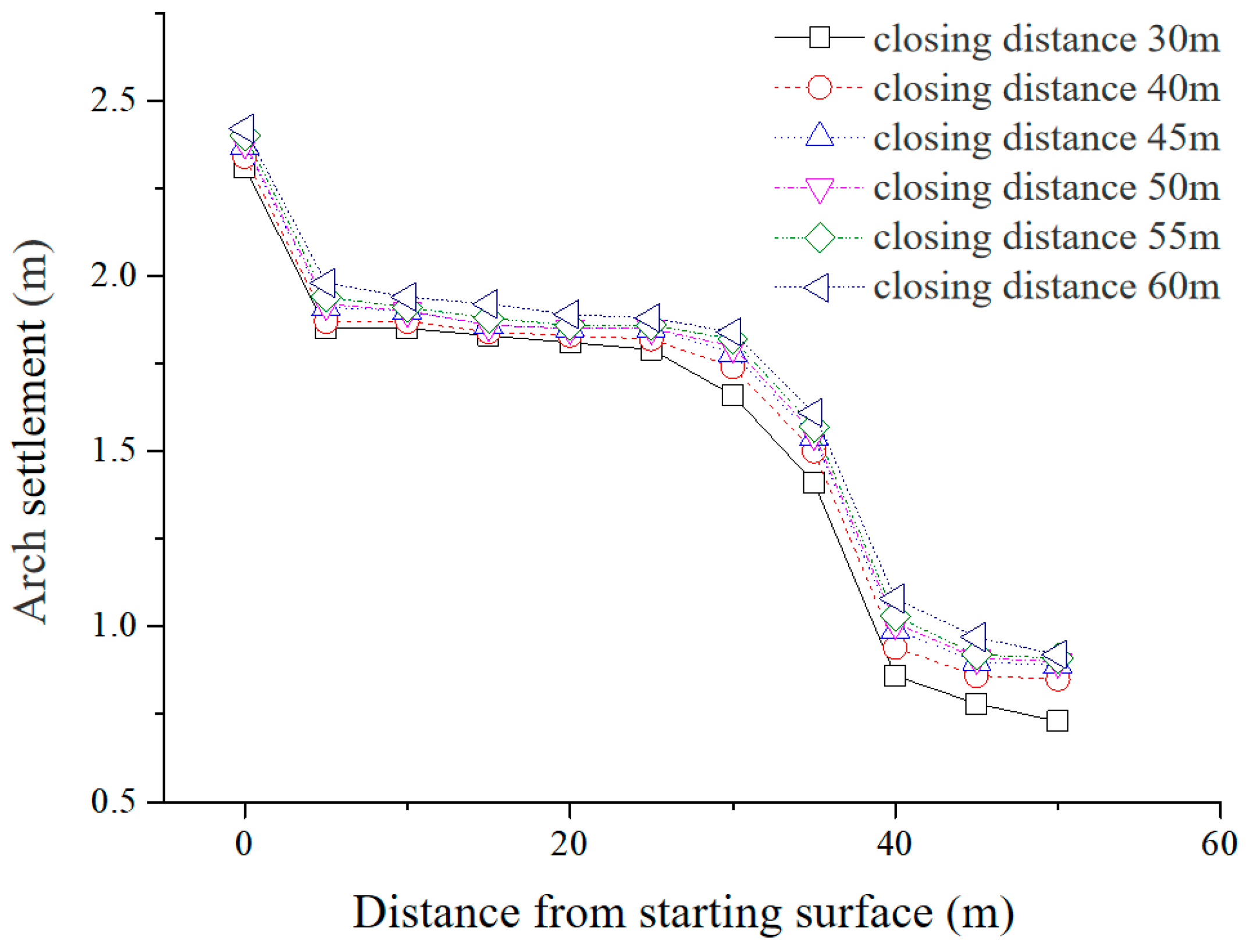
Figure 8 presents the maximum settlement curve of the arch crown for various inverted arch closure distances. It shows that the maximum settlement of the arch crown reaches 24 mm when the inverted arch closure distance is 60 m. The settlement distribution in this case is more realistic and better reflects the actual deformation of the surrounding rock during on-site construction compared to the Mohr–Coulomb criterion-based three-step excavation model.
The numerical analysis results emphasize the importance of considering the effects of stress release and timeliness on the mechanical and deformation properties of surrounding rocks. Failure to account for these factors in the Mohr–Coulomb constitutive model leads to underestimation of settlement and deformation of the arch crown during excavation. In contrast, the modified Burgers constitutive model addresses the strength reduction resulting from stress release and the time-dependent nature of construction steps. As a result, it provides a more accurate representation of the excavation process.
Simulation results using the modified Burgers model show that the deformation at the arch waist of the unclosed section progressively increases with each excavation step. This behavior aligns with the actual monitoring data. However, when using the Mohr–Coulomb model, the deformation at the arch waist of the unclosed section remains stable, which significantly differs from the observed monitoring results. These findings underscore the importance of considering the decrease in rock strength due to stress release after excavation and the time-dependent nature of excavation steps in tunnel excavation simulations.
4. Analysis of the Influence of Tunnel Arch Subsidence
4.1. Impact of Invert Step Distance on Arch Crown Subsidence in a V-Class Surrounding Rock Tunnel
Based on the above method, we calculated the settlement of the arch crown caused by different closure distances using the Burgers creep model for a V-grade surrounding rock, and the results are presented in
Table 3. The analysis shows that as the closure distance increases from 30 m to 60 m, the maximum displacement of the arch crown increases from 13.33 mm to 25.1 mm.
4.2. Influence of Excavation Length of the Inverted Arch of the Class V Surrounding Rock Tunnel on Vault Settlement
The settlement of the arch crown caused by different lengths of the exposed inverted arch (5 m, 4 m, and 3 m) in a V-grade surrounding rock was calculated using the Burgers creep model. The results are presented in
Figure 9 and
Table 4.
The above calculation results show that as the exposed distance of the inverted arch decreases, the maximum settlement of the arch decreases, indicating that a smaller exposed distance of the inverted arch leads to stronger initial support stability and a more pronounced initial support force ring effect. However, the settlement curve shows that the maximum settlement of the arch is not very sensitive to the exposed distance of the inverted arch, indicating that the effect of the exposed distance of the inverted arch on stability is not significant.
4.3. Influence of the Surrounding Rock Class on Arch Settlement
The stability of a tunnel is primarily influenced by the nature of the surrounding rocks. Therefore, in order to investigate the relationship between the closure distance of the inverted arch and the maximum settlement of the initial support arch under different surrounding rock classes, the strength of the surrounding rocks was varied based on the aforementioned model. The Burgers creep model parameters for different levels of surrounding rocks are presented in
Table 2.
The results obtained using the Burgers creep model are shown in
Figure 10 and
Table 5. It is observed that the maximum settlement value of a V-grade surrounding rock vault is larger than that of III and IV surrounding rocks, and the maximum settlement of a IV surrounding rock vault is slightly higher than that of a III surrounding rock vault at each closure distance. Furthermore, with an increase in the closure distance, the maximum settlement value of the vault also increases.
According to the data presented in
Table 5, an increase in the grade of surrounding rocks results in a significant reduction in the displacement value of the tunnel vault, indicating a strong sensitivity of the vault settlement to changes in the grade of surrounding rocks. These observations suggest that the stability of initial support is closely linked to the grade of surrounding rocks. Specifically, when the surrounding rock conditions are good, the inverted arch closure distance can be appropriately increased, and the exposed distance of the inverted arch can also be increased to facilitate the operation of large machinery. Conversely, when the surrounding rock conditions are poor, the inverted arch closure distance should be shortened, and the exposed distance of the inverted arch reduced, while initial support should be promptly applied to ensure the stability of the surrounding rock. Additionally, increasing the length of circular footage and reducing the time of circular footage under good surrounding rock conditions can significantly enhance the stability of the surrounding rock and the tunnel.
5. Conclusions
This study combines indoor experiments and numerical simulations to analyze the tunnel excavation process, considering the time-dependent behavior of the surrounding rock using the Burgers creep model. The research focuses on investigating the influence of the back-arch excavation progress and the back-arch closure length on the settlement of the initial support arch. The key findings of this research are as follows:
- (1)
Decreasing the closure distance of the inverted arch leads to a reduction in the maximum settlement of the vault. This indicates that a smaller closure distance results in stronger stability of the initial support, with a more prominent effect of the initial support force ring. However, the maximum settlement of the vault is found to be insensitive to the exposed distance of the inverted arch. This suggests that the distance of the inverted arch has a less significant impact on the stability of the initial support. For a V-grade surrounding rock inverted arch, the sealing distance can be controlled within a range of 55 m, while for an IV-grade surrounding rock inverted arch, it can be controlled within a range of 70 m. The sealing distance for an III-grade surrounding rock inverted arch depends on specific site conditions.
- (2)
Following mechanized operation, the excavation length of the V-grade surrounding rock inverted arch can be controlled within a range of 5 m at a time.
- (3)
In the case of the same surrounding rock conditions, the stability of the initial support of the tunnel is mainly influenced by the distance between the closure of the elevated arch; the stability of the initial support is less influenced by the elevated arch excavation step; the surrounding rock grade is different; the initial support of the tunnel is influenced by the distance between the closure of the elevated arch; the surrounding rock conditions are better; the stability of the initial support is less influenced by the change in the distance between the elevated arch.
- (4)
The step method is suitable for excavation in Grade III, IV, and V surrounding rocks, and the length of excavation steps can be determined based on the settlement of the vault caused by the excavation.
The numerical model developed in this study is based on the Songgangshan Tunnel and Shimengang Tunnel. The proposed method can be applied to study other sections of the project following the same approach.
Author Contributions
H.F.: Conceptualization, Methodology, Supervision, Project administration. W.X.: Methodology, Software, Data processing, Writing, original draft. Y.W.: Validation, Formal analysis, Writing, review, and editing. All authors have read and agreed to the published version of the manuscript.
Funding
Subject of National Railway Group Co., Ltd. (J2018Z503) and National Natural Science Foundation of China (51978668).
Institutional Review Board Statement
Not applicable.
Informed Consent Statement
Not applicable.
Data Availability Statement
Not applicable.
Acknowledgments
The authors thank the Advanced Research Center, Central South University, for providing the experiment conditions. The authors also express special thanks to the editors and anonymous reviewers for their constructive comments.
Conflicts of Interest
The authors declare that they have no known competing financial interests or personal relationships that could have appeared to influence the work reported in this paper.
References
- Deng, H.-S.; Fu, H.-L.; Shi, Y.; Zhao, Y.-Y.; Hou, W.-Z. Countermeasures against large deformation of deep-buried soft rock tunnels in areas with high geostress: A case study. Tunn. Undergr. Space Technol. 2022, 119, 104238. [Google Scholar] [CrossRef]
- Deng, H.-S.; Fu, H.-L.; Chen, W.; Zhao, Y.-B.; Yi, H.-D. Study on deterioration, cracking mechanism and treatment measures of plain concrete lining with cold joints in high-speed railroad tunnel. Case Stud. Constr. Mater. 2023, 18, e01895. [Google Scholar] [CrossRef]
- Wang, Y.; Guo, J.; Zhao, J.; Yang, X.; Li, W.; Liu, J. Influence of Arch Foot Defect of Primary Support on Mechanical Behaviors of an Arch Frame in Underground Tunnels. Geofluids 2022, 2022, 9593566. [Google Scholar] [CrossRef]
- Wang, K.; Xu, S.; Zhong, Y.; Han, Z.; Ma, E. Deformation failure characteristics of weathered sandstone strata tunnel: A case study. Eng. Fail. Anal. 2021, 127, 105565. [Google Scholar] [CrossRef]
- Shreedharan, S.; Kulatilake, P.H.S.W. Discontinuum–Equivalent Continuum Analysis of the Stability of Tunnels in a Deep Coal Mine Using the Distinct Element Method. Rock Mech. Rock Eng. 2016, 49, 1903–1922. [Google Scholar] [CrossRef]
- Maleki, J.; Pak, A.; Yousefi, M.; Aghakhani, N. A comprehensive FE study for design of anchored wall systems for deep excavations. Tunn. Undergr. Space Technol. 2022, 122, 104340. [Google Scholar] [CrossRef]
- Momeni, E.; Poormoosavian, M.; Tehrani, H.S.; Fakher, A. Reliability analysis and Risk Assessment of Deep Excavations using Random-Set Finite Element Method and Event Tree Technique. Transp. Geotech. 2021, 29, 100560. [Google Scholar] [CrossRef]
- Ye, W.; Wu, Y.; Chen, M.; Gao, C. Temporal and Spatial Effect of Surrounding Rock and Supporting Construction of a Large Soil Tunnel. Adv. Civ. Eng. 2021, 2021, 9962660. [Google Scholar] [CrossRef]
- Chen, J.; Luo, Y.; Li, Y.; Zhao, P.; Xu, D.; Wang, Q. The change of rock mass pressure of Lianchengshan tunnel. Environ. Earth Sci. 2020, 79, 192. [Google Scholar] [CrossRef]
- Peng, W.-Q.; Wang, W.-J.; Yuan, C. Supporting Technology Research in Deep Well Based on Modified Terzaghi Formula. Adv. Civ. Eng. 2018, 2018, 9483538. [Google Scholar] [CrossRef] [Green Version]
- Sun, M.; Zhu, Y.; Li, X.; Zhu, Z.; He, B. Experimental Study of Mechanical Characteristics of Tunnel Support System in Hard Cataclastic Rock with High Geostress. Shock. Vib. 2020, 2020, 8824881. [Google Scholar] [CrossRef]
- Aksoy, C.O.; Oğul, K.; Topal, I.; Poşluk, E.; Gicir, A.; Kucuk, K.; Aldas, G.U. Reducing deformation effect of tunnel with Non-Deformable Support System by Jointed Rock Mass Model. Tunn. Undergr. Space Technol. Inc. Trenchless Technol. Res. 2014, 40, 218–227. [Google Scholar] [CrossRef]
- Cantieni, L.; Anagnostou, G.; Hug, R. Interpretation of Core Extrusion Measurements When Tunnelling through Squeezing Ground. Rock Mech. Rock Eng. 2011, 44, 641–670. [Google Scholar] [CrossRef] [Green Version]
- Zhong, Z.L.; Liu, X.R.; Yuan, F.; Qu, W. Effect of excavation length of inverted arch in one step on stability of multi-arch tunnels in loess. Chin. J. Geotech. Eng. 2008, 30, 462. [Google Scholar]
- Hong, Q.; Lai, H.; Liu, Y.; Ma, X.; Xie, J. Deformation control method of a large cross-section tunnel overlaid by a soft-plastic loess layer: A case study. Bull. Eng. Geol. Environ. 2021, 80, 4717–4730. [Google Scholar] [CrossRef]
- Tan, Z.; Zhao, J.; Guo, X. Analysis of deformation and spatio–temporal effects during construction of a shallow-buried large cross-sectional loess tunnel. Arab. J. Geosci. 2021, 14, 2389. [Google Scholar] [CrossRef]
- Rehman, Z.U.; Hussain, S.; Tahir, M.; Sherin, S.; Mohammad, N.; Dasti, N.; Raza, S.; Salman, M. Numerical modelling for geotechnical assessment of rock mass behaviour and performance of support system for diversion tunnels using optimized Hoek-Brown parameters. Min. Miner. Depos. 2022, 16, 1–8. [Google Scholar] [CrossRef]
- Du, M.; Wang, X.; Zhang, Y.; Li, L.; Zhang, P. In-situ monitoring and analysis of tunnel floor heave process. Eng. Fail. Anal. 2019, 109, 104323. [Google Scholar] [CrossRef]
- Ning, Z.X.; Xue, Y.G.; Su, M.X.; Qiu, D.H.; Zhang, K.; Li, Z.Q.; Liu, Y.M. Deformation characteristics observed during multi-step excavation of underground oil storage caverns based on field monitoring and numerical simulation. Environ. Earth Sci. 2021, 80, 222. [Google Scholar] [CrossRef]
- Deng, H.-S.; Fu, H.-L.; Yue, S.; Huang, Z.; Zhao, Y.-Y. Ground loss model for analyzing shield tunneling-induced surface settlement along curve sections. Tunn. Undergr. Space Technol. 2022, 119, 104250. [Google Scholar] [CrossRef]
- Aso, A.; Duan, Z. Fractional Burgers models in creep and stress relaxation tests. Appl. Math. Model. 2020, 77, 1894–1935. [Google Scholar] [CrossRef] [Green Version]
- Lin, H.; Zhang, X.; Cao, R.; Wen, Z. Improved nonlinear Burgers shear creep model based on the time-dependent shear strength for rock. Environ. Earth Sci. 2020, 79, 149. [Google Scholar] [CrossRef]
- Ma, Y.; Yao, Q.; Wang, J.; Sun, S.; Qiu, Z. Time-Dependent Creep Constitutive Model of Roadway Surrounding Rock Based on Creep Parameters. Geofluids 2022, 2022, 7981192. [Google Scholar] [CrossRef]
| Disclaimer/Publisher’s Note: The statements, opinions and data contained in all publications are solely those of the individual author(s) and contributor(s) and not of MDPI and/or the editor(s). MDPI and/or the editor(s) disclaim responsibility for any injury to people or property resulting from any ideas, methods, instructions or products referred to in the content. |
© 2023 by the authors. Licensee MDPI, Basel, Switzerland. This article is an open access article distributed under the terms and conditions of the Creative Commons Attribution (CC BY) license (https://creativecommons.org/licenses/by/4.0/).


