Article

Influence of Concrete Shrinkage on the Behavior of Carbon Short-Fiber-Reinforced Concrete (CSFRC) under Tension

1
Chair of Concrete and Masonry Structures, Technical University of Munich, 80333 Munich, Germany
2
Faculty of Civil Engineering, Architecture, and Geodesy, University of Mostar, 88000 Mostar, Bosnia and Herzegovina
*
Author to whom correspondence should be addressed.
Appl. Sci. 2023, 13(12), 7081; https://doi.org/10.3390/app13127081
Submission received: 22 May 2023 / Revised: 1 June 2023 / Accepted: 5 June 2023 / Published: 13 June 2023
(This article belongs to the Section Civil Engineering)

Abstract

:
Carbon short-fiber-reinforced concrete (CSFRC) is a novel material obtained by adding and mixing carbon fibers into fresh concrete. In this way, the concrete behavior is changed, and concrete no longer undergoes brittle failure under tension. Specifically, when concrete is reinforced with short carbon fibers, its tensile characteristics become similar to those of steel. For example, CSFRC exhibits a distinct ductility, enabling the concrete to withstand substantial damage before failure. This results in a higher energy dissipation capacity, which consequently also increases the tensile strength of the concrete. Accordingly, the tensile strength of CSFRC is about 400% higher than that of plain concrete and almost double that of UHPC. Because of the differences in mechanical performance compared to conventional concrete, extensive experimental and theoretical research is needed to characterize the behavior of CFRSC. Our main aim in this research is to investigate and describe the load bearing and deformation behavior of CSFRC, as well as the related damage processes.

1. Introduction

Concrete is the most commonly used building material, having been used for hundreds of years; needless to say, it has been the subject of many research studies. From the very beginning of its use, it was clear that concrete has high compressive strength and low tensile strength. In order to address the weakness of concrete under tension, concrete started being reinforced with steel bars (reinforcement) in the tensile zone. In this way, the concrete tensile properties are improved, and this also enables the concrete to be used at high tensile stresses. However, high tensile stresses cause cracking in concrete, which, in an aggressive environment, can cause steel corrosion, thus endangering the durability of reinforced concrete. Adding steel bars to concrete also increases the structure weight, especially for structures requiring a significant amount of reinforcement, such as bridges. In this way, a self-weight load, which decreases the bearing capacity of structures, is significant. To avoid these shortcomings caused by adding steel bars to concrete, reinforcing concrete with other materials (e.g., natural fibers [1]), instead of steel bars, has been considered. One such material is carbon fibers.
There are many ways of using carbon fibers as a building material, and this is the subject of numerous research studies. If the steel reinforcements were replaced with carbon-fiber-reinforced polymer (CFRP) bars, then the weight of the reinforced concrete structure would be significantly reduced, and the corrosion risk would be eliminated [2]. By reinforcing concrete in this way, a high strength-to-weight ratio would be achieved [3], while the displacement would increase up to 1.86 times compared to that of the concrete reinforced with steel bars, and the ductile performance would be 50% higher [4]. The bond between the CFRP bars and the concrete has a huge influence on the behavior of the structure, which was researched in [2,5].
Carbon fiber laminate sheets present another way of implementing carbon fiber into building materials [6,7,8,9,10]. The longitudinal carbon fiber sheets (CFSs) wrapped around the bottom surface of the reinforced concrete beams act together with the bottom longitudinal reinforcement to resist bending moments, consequently reducing the development of strain on the bottom longitudinal reinforcement [6]. They also improve the torsional capacity of beams [7] and increase the structural stiffness, strength, and energy dissipation capacity of a beam–column joint [8,9]. Wrapping concrete cylinders with CFS also increases their compressive axial strength [10]. The use of CFS is especially suitable for structure rehabilitation and renovation.
The third application of carbon fibers in civil engineering is reinforcing concrete with short carbon fibers, hereinafter called carbon short-fiber-reinforced concrete (CSFRC). The efficiency of this type of concrete reinforcement depends on the angle between the carbon fiber direction and the stress direction and percentage of carbon fibers in the concrete mixture [11,12,13]. Fiber orientation can be directed as desired using a special technique. Thus, for 1 vol% of carbon fibers in the cement paste aligned in the stress direction, there is a 5.6-foldincrease in the strength of flexural cement paste compared with plain cement paste, while for 3 vol% of carbon fibers aligned in the stress direction, the increase in flexural cement paste strength is around 14.40-fold. In contrast to the flexural strength, the compressive strength decreases around 1.17 times for 1 vol% of carbon fibers and 1.22 times for 3 vol% of carbon fibers [11,14]. For 1 vol% of randomly dispersed carbon fibers, there is around a 2.45-fold increase in strength for the flexural cement paste compared with the plain cement paste [11]. In hardened concrete, the flexural concrete strength increase is around 2.70- and 4.65-fold for the specimen with 1 vol% and 3 vol% of carbon fibers, respectively, compared with unreinforced concrete. These two values correspond to the 0° alignment angle between the direction of fibers and stress. At an alignment angle of 30°, the flexural concrete strength increase is around 1.13-fold for 1 vol% and around 1.57-fold for 3 vol% of carbon fibers compared with unreinforced concrete [13]. These results show that the influence of carbon fibers on concrete strength decreases with increasing angular deviation between the directions of fiber and stress. This influence can be considered effective for angular deviations up to 20°, while there are hardly any effects at 30°, and no effects can be seen at 40° [13]. In order to achieve a suitable alignment angle between the directions of carbon fiber and stress, 3D concrete printing is the most efficient tool [15], while an even distribution of carbon fibers in cement paste can be achieved using silica fume (SF) [16]. However, it is necessary to be careful when applying SF because, besides the positive influence on the concrete mechanical parameters (strength, elasticity modulus, etc.), it can also have a negative influence, e.g., increasing concrete shrinkage [16,17,18,19,20].
Reinforcing cement paste or concrete with short carbon fibers causes changes in its behavior, of which only some changes will be mentioned here. For example, shrinkage can cause cracking of cement paste at an early age. However, adding carbon fibers to cement paste reduces the shrinkage and prevents cracking at an early age [17,19,20,21]. The concrete behavior changes as well. It is known that unreinforced concrete subjected to tensile load or bending suddenly undergoes brittle failure without any prior notice. Unlike unreinforced concrete, CSFRC shows pseudo-ductile behavior, so the concrete no longer experiences brittle failure [13]. Between the time of appearance of the first crack and concrete failure, a dense network of cracks will develop, which causes large energy dissipation. These changes in concrete (appearance and connection of micro-cracks) during the loading process also cause changes in its thermo-electrical features. Thus, there is high concrete electrical conductivity before loading and appearance of the first crack that decreases during the process of loading and damage. The electrical resistivity is inversely proportional to the electrical conductivity, so it is lower at the beginning of the loading process and increases during loading and damage of the structure. Based on this fact, it is possible to detect damage in the CSFRC over time in a nondestructive way. Because of its ability to be used as a self-sensor, the CSFRC is also considered a smart concrete [22,23,24,25,26,27,28,29,30].
It is obvious from the previous brief description that CSFRC has very complex behavior; hence, the main aim of this paper is to contribute to understanding its behavior. For that purpose, 24 CSFRC specimens were tested under tension, whereby strain gauges and digital image correlation (DIC) were used. The obtained results enabled the determination of the constitutive stress–strain law and damage processes in the specimens. Specimens of different ages were tested with short-term static tensile load. Unlike the articles from the literature, where the tensile strength and other mechanical parameters were mostly tested for specimens of only a single age (mostly 28 days), the ages of specimens in this work were 9, 14, 21, 28, 35, 49, 70, and 91 days. In this way, it is possible to estimate the influence of the specimens’ age on their behavior. Based on those results, the influence of concrete shrinkage was investigated with the aim of highlighting its importance.

2. Materials and Methods

2.1. Raw Materials and Mixing Procedure

Carbon fibers were uniformly cut to a length of 3 mm, and their other properties were as follows: diameter 7 µm, tensile strength 4137 MPa, modulus of elasticity 242 GPa, and ultimate tensile strain of 1.5%. Before incorporation into the cement paste, they were oxidatively heated for 2 h in an open furnace at 425 °C. Cement CEM 52.5 R type was used as a binder achieve high early strength. Apart from cement, the concrete mixture also contained quartz powder and quartz sand. A superplasticizer was added to decrease the amount of water in the mixture, while a good dispersion of carbon in the mixture was achieved by adding silica fume and the heat pretreatment of fibers. The proportion of each component in the mixture, as a percentage of the concrete weight, is shown in Table 1.
Once all raw materials were available, it was necessary to mix them. The first step was to place the cement, silica fume, quartz powder, and quartz sand into the mixer and then mix them while in a dry state. After the dry components were well mixed, water and superplasticizer were slowly added. The mixing process was continued until the bulbs in the mixture were dissolved. Finally, carbon fibers were added, and two mixing cycles lasting for around 1 min each were performed.

2.2. Printing Process and Curing Procedure

Once the mixing process was completed, the mixture was transported in plastic bags to the 3D printer developed at Technical University of Munich (TUM) [31] for printing of the specimens. More details about the 3D printing process can be found in [32,33]. The specimens had the shape of a “dog bone”, the height of which was about 445 mm, the thickness about 50 mm, the width and height at midspan about 50 mm, and the width on both ends about 100 mm (Figure 1a). During the printing, the desired fiber alignment was achieved by pushing concrete mixture through a nozzle of 4 mm diameter (Figure 1b). This printing process ensured that the deviation in the angle between the directions of the fibers and stress was mainly in the range of ±10° [13].
Once the printing process was completed, the specimens were placed in a formwork and left in an area with 100% RH for 1 day in order to harden. The formwork was used only to smooth the specimen sides for the installation of measuring equipment. Afterwards, the specimens were cured under water for 6 days and finally in an area with controlled conditions (RH 65 ± 5% and temperature 20 ± 2 °C) until testing.

2.3. Testing Procedure

Once the curing process was completed and the specimens reached the desired age for testing, four strain gauges were glued onto them (Figure 1c) in the direction of tensile load: two on the upper edge of the testing area and two on the bottom edge of the testing area (Figure 1a,c). The surface opposite to the specimen was prepared for DIC (Figure 1d). After the preparation of strain gauges and the DIC surface was complete, the specimen was installed in the testing device. Finally, the specimen was ready for testing and subjected to a short-term static tensile load. Tests were performed using the direct tensile strength testing method with displacement-controlled tensile-loading. The velocity of the load increase was 0.003 mm/s, and the load was increased until the specimen broke.
A total of 24 specimens were tested at different ages (at the age of 9, 14, 21, 28, 35, 49, 70, and 91 days) such that three different specimens are tested for each age. The results for each specimen were analyzed such that, e.g., the final stress–strain diagram actually showed the average value of all four gauges on the observed specimen. These tests lasted from 160 up to 260 s, and two pictures were taken in one second for DIC. The pictures were analyzed using GOM Correlate 2018 software.

3. Results

3.1. Tensile Strength, Stress Causing First Crack Appearance, and Ultimate Tensile Strain

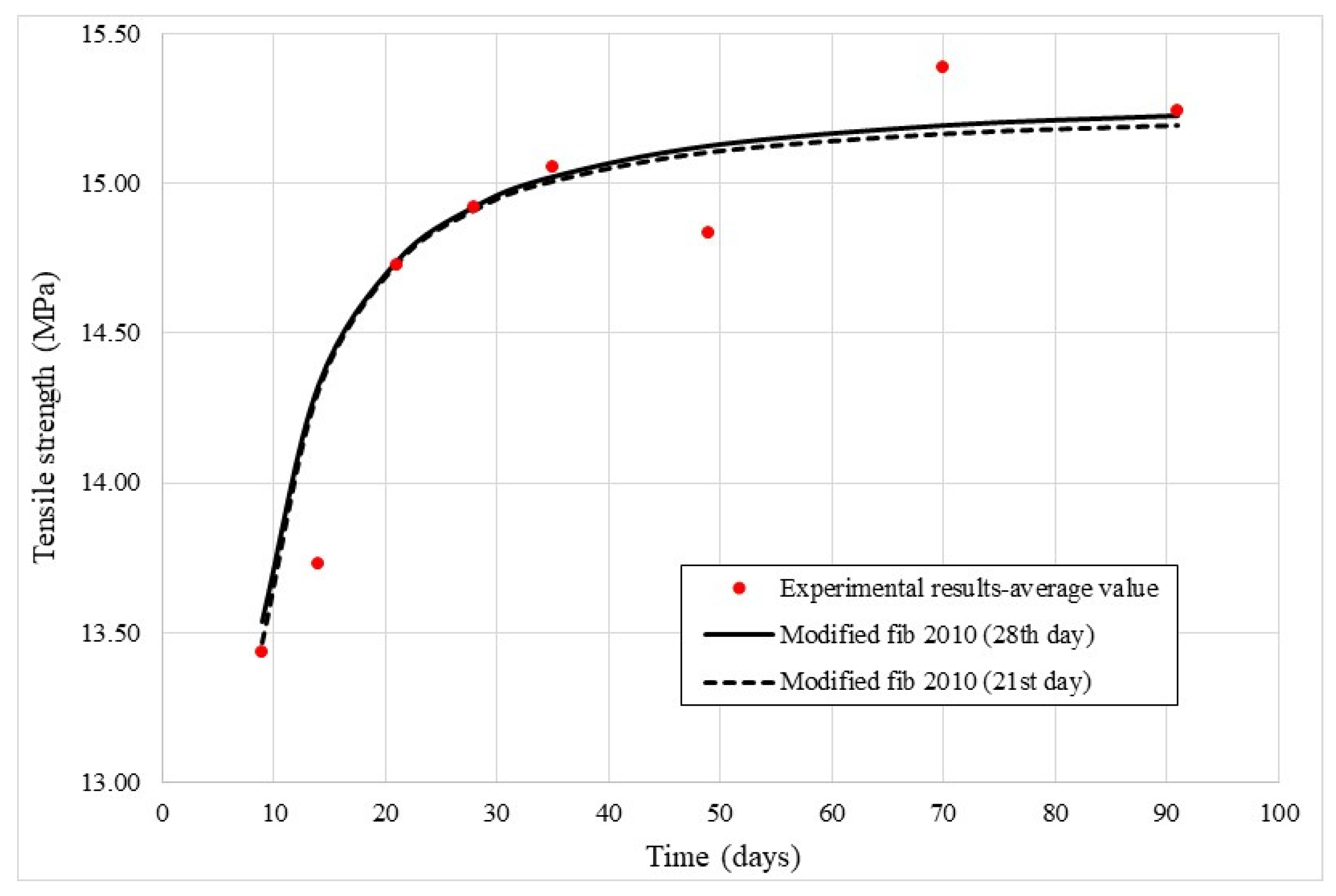
The maximal tensile load caused specimen failure, and the ratio of this load to the specimen area at the midspan is the CSFRC tensile strength. Table 2 provides the results for all specimens.
Figure 2 is a graphical view of the results from Table 2.
Analyzing the results shown in Table 2 and Figure 2, it is clear that the tensile strength at the age of 9 days is 90% of the tensile strength at the age of 28 days. In [34], the tensile strength at the age of 9 days is 70–80% of the tensile strength at the age of 28 days, depending on the concrete mixture content. This shows that carbon fibers accelerate the development of tensile strength, and autogenous shrinkage in the young concrete does not cause the formation of micro-cracks. As the tensile strength at the age of 21 days is approximately 99% of the tensile strength at the age of 28 days, it can be concluded that the CSFRC has already hardened at the age of 21 days, which enables it to be exploited at an earlier timepoint than conventional concrete.
The results provided in [35] for predicting the development of mechanical features (elasticity modulus, compressive strength, etc.) in conventional concrete over a specific time span show that fib Model Code 2010 [36] has lower derivation from the experimental results than other standards. Hence, expressions from [36] are modified for the temporal prediction of CSFRC tensile strength development.
The following equation is proposed for prediction of tensile strength development of CSFRC over time based on the tensile strength at the age of 28 days:
f c t t = e 0.025 · 1 28 t 1.40 · f c t 28 .
The following equation is proposed for the same prediction but at the age of 21 days:
f c t t = e 0.035 · 1 21 t 1.50 · f c t 21 .
The parameters for Equations (1) and (2) are as follows:
  • f c t ( t ) —tensile strength of CSFRC at the age ( t );
  • f c t ( 28 ) —tensile strength of CSFRC at the age of 28 days;
  • f c t ( 21 ) —tensile strength of CSFRC at the age of 21 days.
The prediction results calculated using Equations (1) and (2) are shown in Figure 2 and clearly show good agreement with the experimental results. The disagreement in the results for the ages of 14, 49, and 70 days is 4%, 1.8%, and 1.45% and can be ignored.
As the tensile strength is around 3 MPa [36] for specimens manufactured from normal concrete and around 8 MPa [37] for those manufactured from ultra-high-performance concrete (UHPC), it is evident that the tensile strength of CSFRC is about 400% higher than that of normal concrete and about 88% higher than that of UHPC.
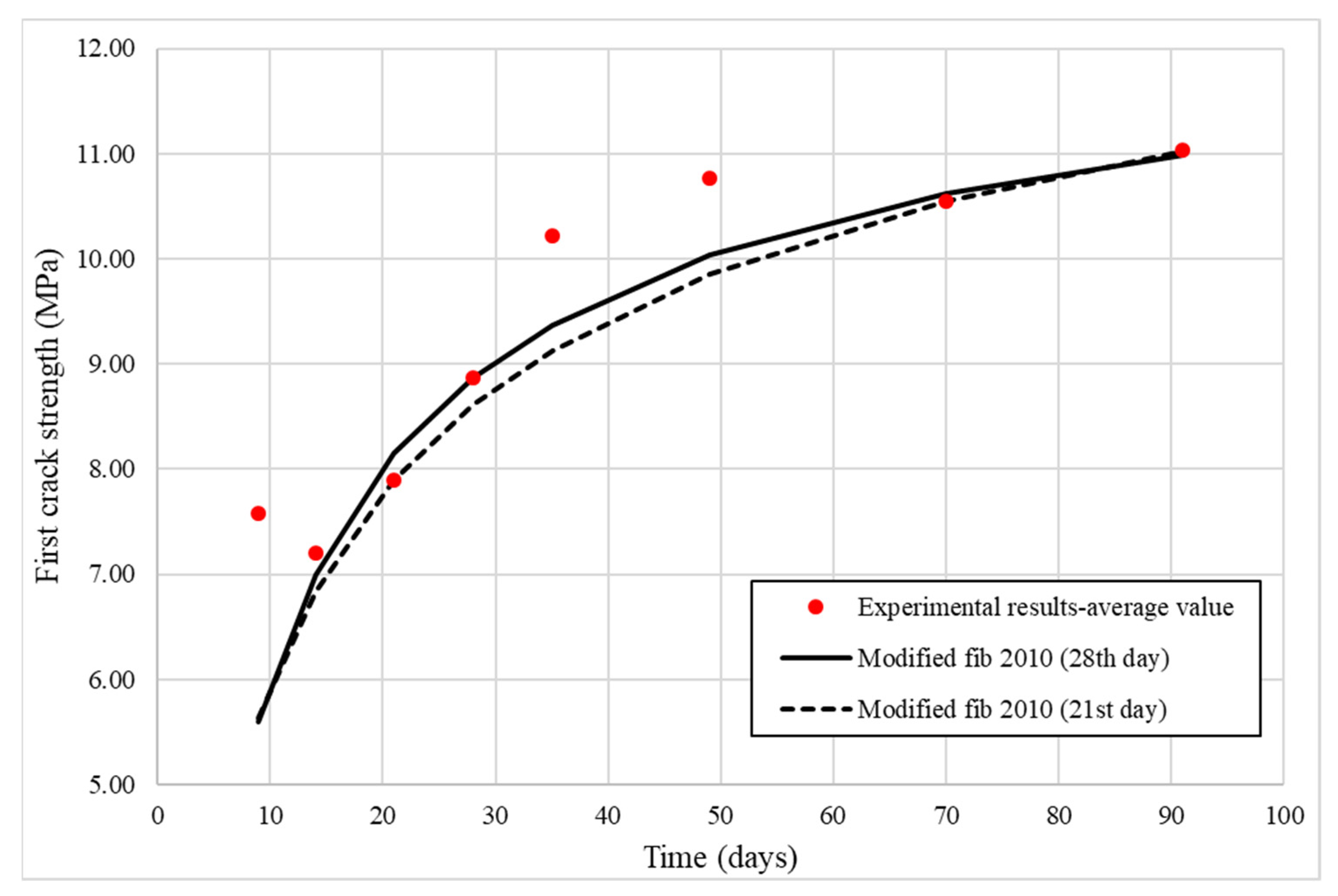
An important parameter in the analysis of CSFRC behavior is the stress at the time of appearance of the first crack (nonlinearity), also referred to as the first crack strength. Table 3 and Figure 3 show that this value increases with aging.
Based on fib Model Code 2010 [36], modified equations are proposed for the prediction of this stress.
In doing so, Equation (3) aims to predict the stress development of CSFRC over time based on the tensile strength at the age of 28 days:
σ c r t = e 0.38 · 1 28 t 0.70 · σ c r 28 ,
whereas Equation (4) intends to predict the stress development based on the tensile strength at the age of 21 days:
σ c r t = e 0.64 · 1 28 t 0.50 · σ c r 21 ,
where
σ c r t is stress causing crack formation at age ( t ).
In Figure 3, good agreement is observed between the experimental results and those obtained through Equations (3) and (4). The highest disagreement (not considering the age of 9 days) is about 10% at the age of 35 days. At the age of 9 days, the disagreement is about 26%, but the material at this age is not yet ready for exploitation, so these equations can be reliably used for prediction in the exploitation period.
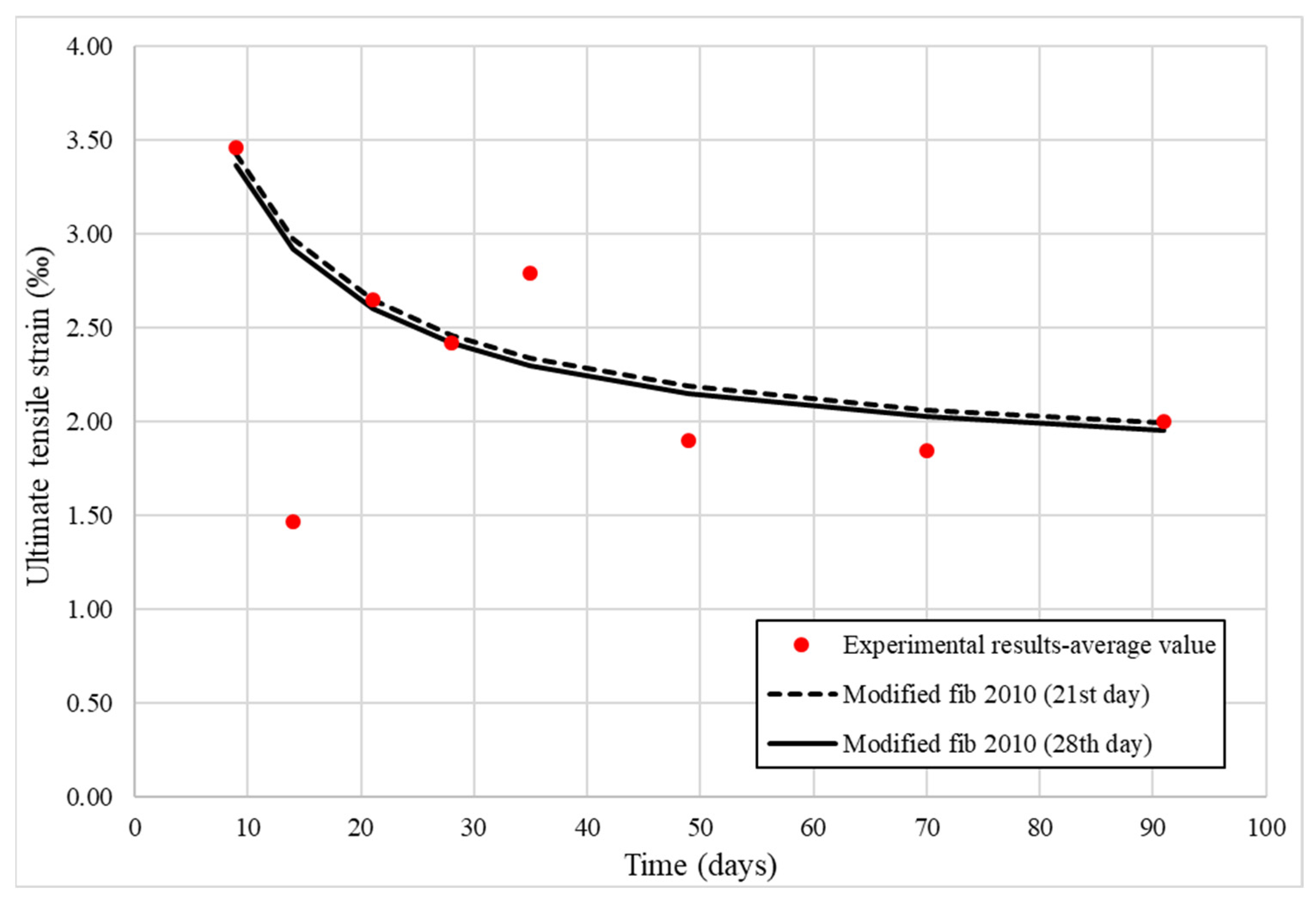
To ensure the possibility of comprehensively defining the constitutive law of material behavior, ultimate tensile strain is also an important parameter to consider. This strain is present in CSFRC immediately prior to failure. Table 3 and Figure 4 show that the value of this parameter decreases with aging. Reasons for this decrease will be explained later in this paper.
Based on the fib Model Code 2010 [36], modified equations are proposed for prediction of this ultimate tensile strain.
In doing so, Equation (5) aims to predict the ultimate strain development of CSFRC over time based on the ultimate tensile strain at the age of 28 days:
ε u l t = β ( t = 28 ) β ( t ) · ε u l 28 ,
whereas the intention of Equation (6) is to predict the ultimate strain development of CSFRC over time based on the ultimate tensile strain at the age of 21 days:
ε u l t = β ( t = 21 ) β ( t ) · ε u l 21 ,
where
β ( t ) is temporal coefficient calculated according to Equation (7):
β t = 1 e 0.25 · t 0.5 ,
and
ε u l t is ultimate tensile strain at the age ( t ).
Good agreement is observed when comparing the experimental results with those obtained through Equations (5) and (6) (Figure 4). The disagreement in the results is lower than 2% at the ages of 9, 21, 28, and 91 days but about 16%, 15%, and 12% at the ages of 35, 49, and 70 days, respectively. The highest disagreement is at the age of 14 days, but at this age the material is still too young for exploitation, so it can be concluded that the proposed equations provide good agreement with the experimental results in the potential exploitation period (after 21 days of age).

3.2. Elasticity Modulus

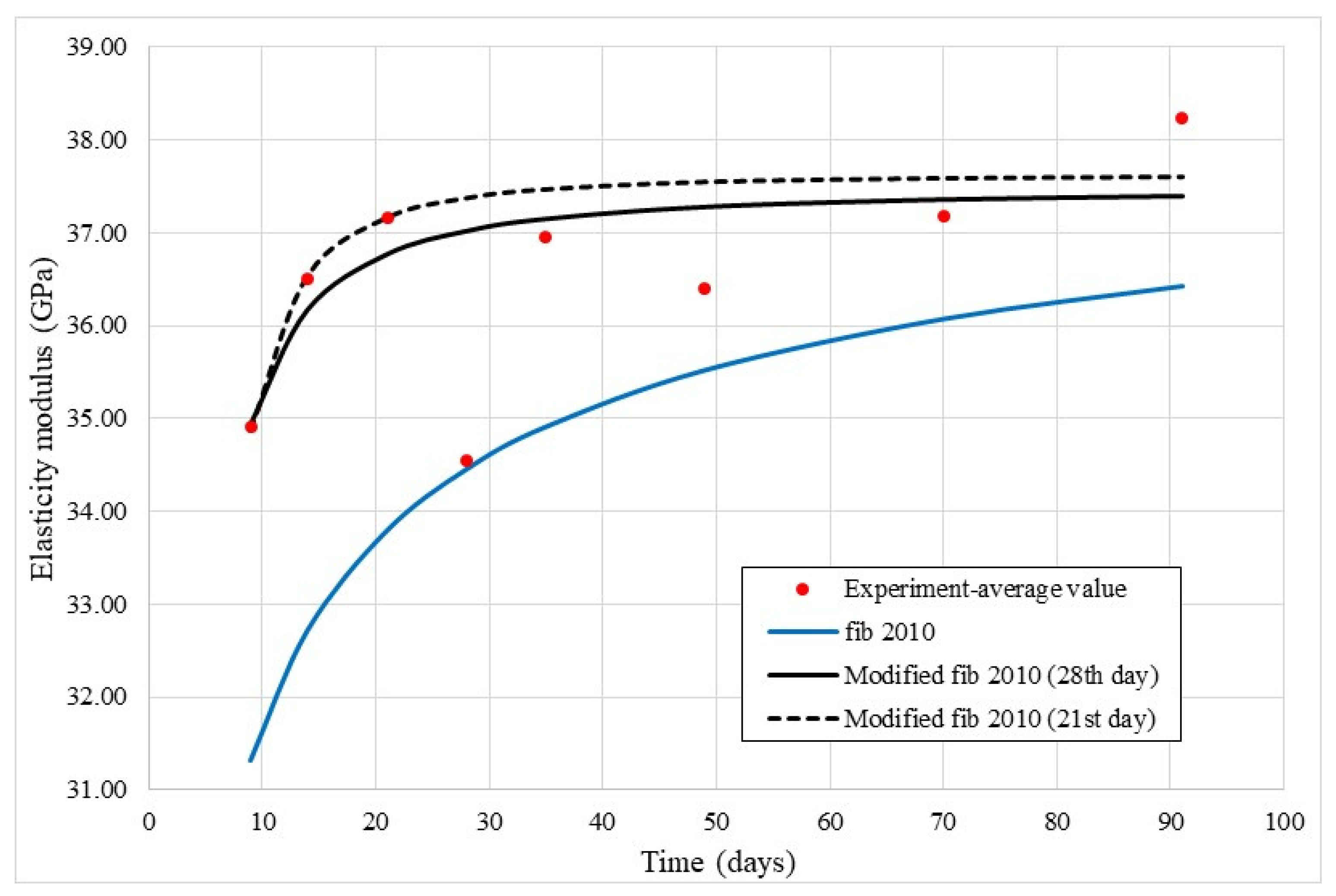
For each specimen, a stress–strain relation can be established for each of the four strain gauges. Consequently, the elasticity modulus and the stress–strain ratio can be calculated. The elasticity modulus is calculated in a linear region when the stress is between 10 and 45% of tensile strength. After the elasticity modulus has been calculated for each strain gauge, the average value is calculated. This value represents the elasticity modulus of the specimen, and the determined values are shown in Table 2 and presented in Figure 5.
The results obtained in this work disagree with those in [38], which show that the elasticity modulus of unreinforced concrete shows significant development in the first 5–10 days and thereafter remains near-constant over time. Unlike the work in [38], the elasticity modulus is observed here to increase by 6.5% between the 9th and 21st day. Hence, it can be said that the carbon fibers contribute to increasing the elasticity modulus up to the 21st day of age.
However, the carbon fibers also influence elasticity modulus development after 21 (or 28) days of age. The results presented in [39] show that for unreinforced concrete, not having been cured for the whole time of its aging, the elasticity modulus will significantly decrease after the 21st (or 28th) day. The results in this work show elasticity modulus either insignificantly decreases after the 21st day (7%, 0.6%, and 2% for 28, 35, and 49 days of age) or slightly increases (2.85% for 90 days of age). The elasticity modulus at the age of 70 days is equal to that at the age of 21 days. Thus, it can be said that carbon fibers prevent degradation of the elasticity modulus caused by concrete drying (shrinkage) [39] after 21 days of age and allow it to remain almost constant over time.
The results for prediction of elasticity modulus development over time using fib Model Code 2010 [36] are shown in Figure 5 and indicate that this code cannot be successfully used to predict the development of CSFRC elasticity modulus over time. Thus, in this work, two equations for such a prediction are proposed. One equation is for prediction of the elasticity modulus of CSFRC at the age of 28 days, and the other at the age of 21 days. Both equations are a modification of fib Model Code 2010 equation [36].
In doing so, Equation (8) aims to predict the elasticity modulus development of CSFRC over time based on the elasticity modulus at the age of 28 days:
E c t = e 0.0841 · 1 28 t 1.55 · E c 28 ,
whereas Equation (9) intends to predict the elasticity modulus development of CSFRC over time based on the elasticity modulus at the age of 21 days:
E c t = e 0.0123 · 1 21 t 2.15 · E c 21 ,
where
E c ( t ) is elasticity modulus of CSFRC at the age of (t).
The prediction results calculated using Equations (8) and (9) are shown in Figure 5. It is clear that there is good agreement between the experimental results and those obtained through (8) and (9). The disagreement in results for Equation (9) at the ages of 28, 35, 49, 70, and 91 days is 7.6%, 1.4%, 3.1%, 1.1%, and 1.6%, respectively, and can be ignored. Equation (8) underestimates elasticity modulus at the ages of 14 and 21 days (0.9% and 1.1%) while the differences are lower after other numbers of days, except 91, than for Equation (9). At the age of 91 days, Equation (8) underestimates the elasticity modulus up to 2.2%. According to the obtained results, both equations can be successfully used for the prediction of CSFRC elasticity modulus development.
Temporal CSFRC elasticity modulus development can be expressed regarding its tensile strength at the age of 21 days according to Equation (10):
E c t = e 0.0123 · 1 21 t 2.15 · f c t 21 1.344 .

3.3. Stress–Strain Curve

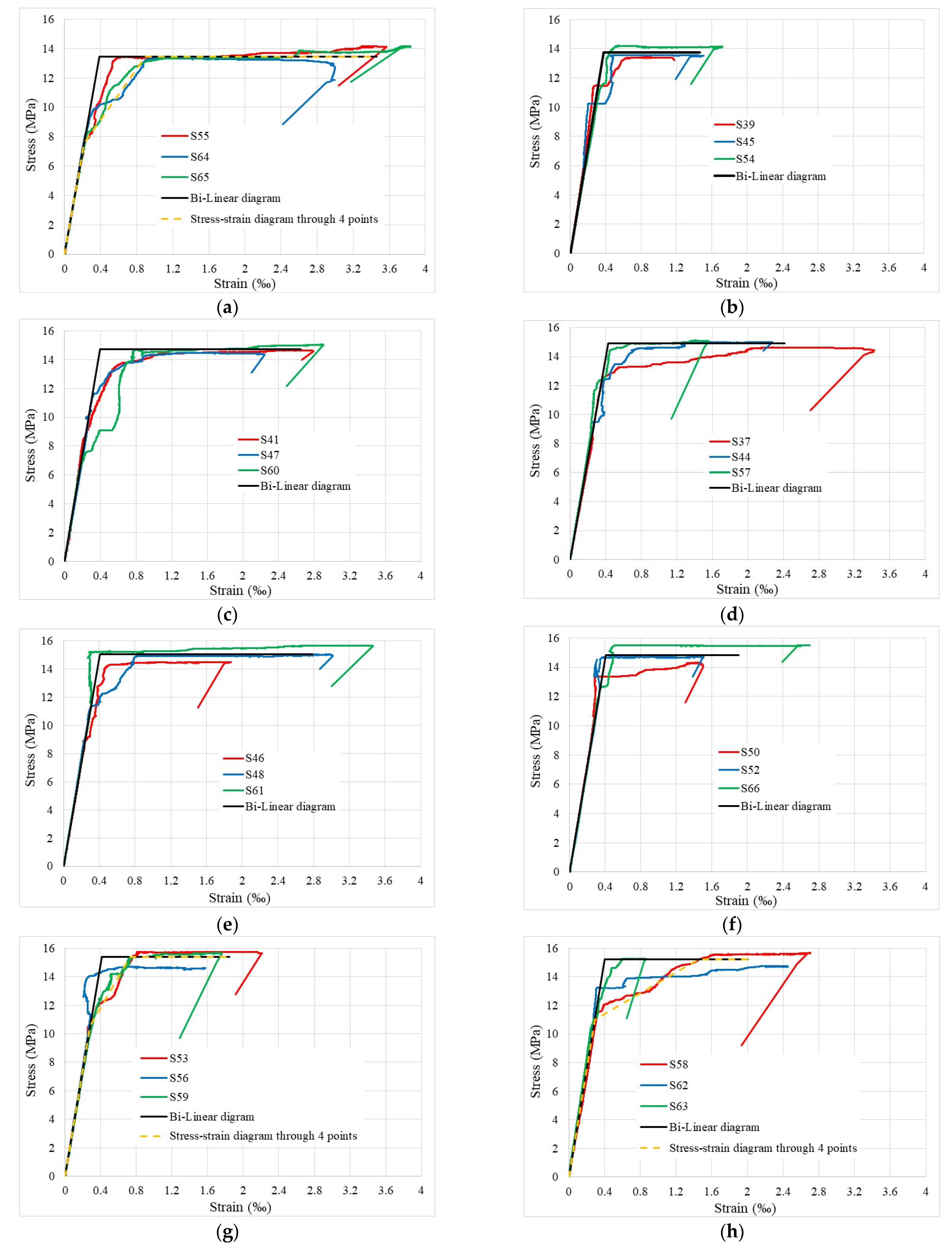
As was mentioned earlier in Section 2.3, the stress–strain curve of some specimens is presented based on the average value of all four strain gauges. The results for all specimens, classified by the age of specimens in the testing time, are provided in Figure 6a–h. In this figure, the mathematical models (bi-linear diagram or/and four-point stress–strain curve) for CSFRC behavior prediction are proposed, given the loading time, in addition to the experimental results.
The CSFRC load-bearing behavior can be divided into the three “life periods”:
  • The growing up period or “childhood”;
  • Maturity or “the best period of life”;
  • The “old age period”.
The 9- and 14-day-old specimens belong represent the first “life period”. Figure 2 and Figure 6a,b show that in this period, the CSFRC has not achieved the full tensile strength. As a consequence, the corresponding specimens suffer significant strain (Figure 6a) and damage (Section 3.5), which is especially obvious at the age of 9 days. These concrete specimens have lower strength, so new cracks will open before the fibers rupture. Therefore, significant nonlinearity of CSFRC already appears at about 55% of the CSFRC tensile strength at the age of 9 days (Figure 3 and Figure 5a), which causes elasticity modulus softening in this region. For that reason, the bi-linear model may underestimate the damage in the region where the stress ranges from 55% to 100% of the CSFRC tensile strength (Figure 2, Figure 3 and Figure 6a). Hence, to predict CSFRC behavior after 9 days of age, the stress–strain model through four points is proposed together with the bi-linear model (Figure 6a). Because of significant damage in the CSFRC, there is large energy dissipation, and hence the introduction of a huge amount of external energy is required to break the specimen. This is because the average ultimate tensile strain, as shown in Figure 6a, is about 3.5‰. At the age of 14 days, specimens have slightly higher concrete tensile strength, but the elasticity modulus also increases. For this reason, a stronger connection between fibers and concrete is achieved, given that there is only slight softening of the CSFRC elasticity modulus in the region between the appearance of first micro-cracks (about 55% of CSFRC tensile strength—Figure 2 and Figure 3) and the CSFRC reaching sufficient tensile strength (Figure 6b). Sudden strain growth (red and blue line in Figure 6b at stress of 10–12.5 MPa) indicates that full bonding between the concrete and the fibers has not yet been achieved through the entire specimen. Since there is only slight softening of the elasticity modulus, a bi-linear diagram is proposed (Figure 6b) for behavior prediction. As these specimens are less damaged, they dissipate lower amounts of energy, so their average ultimate tensile strain is around 1.5 ‰. Concrete shrinkage also contributes to differences in behavior between specimens at the ages of 9 and 14 days, but since there are two different parallel processes in this life span in addition to aging and shrinkage development, it is impossible to define their particular influence on specific details without further comprehensive research.
The second period—“the best period of life” or maturity—comprises specimens tested at the ages of 21, 28, 35, and 49 days (Figure 6c–f). The latter is actually in a state of transition from period two to three. From all 12 specimens in this period, it is obvious that the CSFRC elasticity modulus softening in the region of micro-nonlinearity (stress between 60% and 100% of the CSFRC tensile strength) can be ignored, so the bi-linear diagrams are proposed as behavior prediction models (Figure 6c–f).
The average ultimate strains of specimens 21, 28, and 35 days old are 2.65‰, 2.45 ‰, and 2.8‰, while specimens tested at the age of 49 days have an average ultimate strain of 1.90‰ (Figure 6c–f). This decrease in average ultimate tensile strain of 49-day-old specimens is a consequence of concrete shrinkage. Namely, the concrete shrinkage on the 21st day is about 76% of the concrete shrinkage on the 91st day, while on the 49th day the concrete shrinkage is about 88% of the concrete shrinkage on the 91st day [40]. This difference in the magnitude of concrete shrinkage causes differences in the average ultimate strains, and the influence of concrete shrinkage on the CSFRC behavior will be briefly presented in Section 3.4.
Figure 6g,h show CSFRC behavior in period three—the “old age period”. We can see from Figure 6g,h that average ultimate tensile strain is similar to that in 49-day-old specimens. Thus, specimens tested at the age of 70 days have an average ultimate tensile strain of 1.85‰, while the average ultimate strain of 91-day-old specimens is 2.0‰. Unlike the specimens tested at the age of 49 days, the specimens tested at the ages of 70 and 91 days show a tendency of softening CSFRC elasticity modulus in the region of micro-nonlinearity—when tensile stresses are between 70 and 100% of CSFRC tensile strength (Figure 6g,h). It is possible that the bi-linear material models underestimate CSFRC damage in this region, so four-point stress–strain models are also proposed (Figure 6g,h). It is also obvious that the damage in this region is more significant for the specimens tested at the age of 91 days than those tested at the age of 70 days, which results in a higher capacity for energy dissipation and, thereby, higher average ultimate tensile strain. This is caused by concrete shrinkage and will be explained in Section 3.4.
Nonetheless, it is clear that CSFRC, unlike unreinforced concrete, has highly ductile behavior, which diminishes over time because of concrete shrinkage.

3.4. Concrete Shrinkage Influence on the CSFRC Behavior

Concrete shrinkage evidently influences CSFRC behavior and hence this influence, which is in fact the influence of carbon fiber reinforcement on concrete shrinkage, will be briefly explained. For this purpose, the similarities with classical reinforced concrete structures are considered [41,42,43].
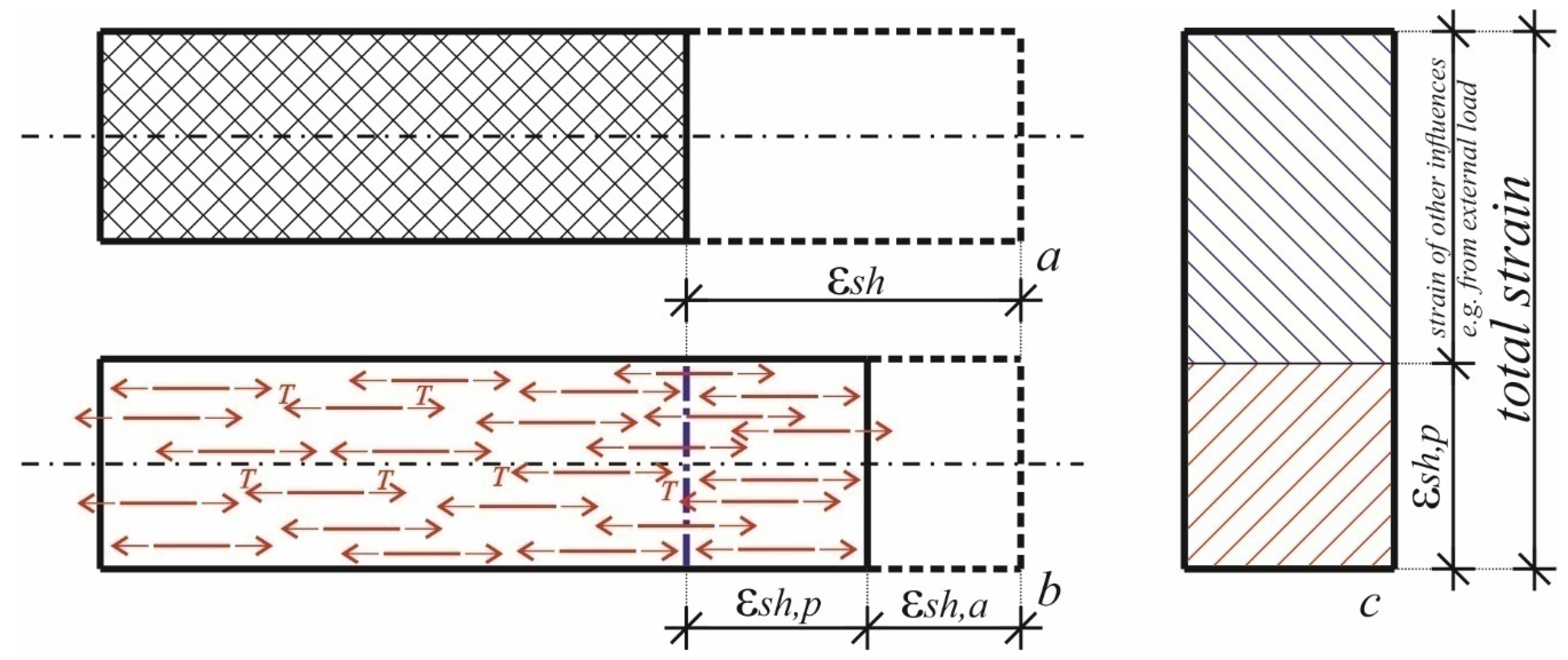
Concrete without reinforcement is shortened due to shrinkage— ε s h (Figure 7a)—without causing any stress in concrete members. Since these shrinkage strains do not cause any stress in concrete members, they are not strictly a strain in the classical sense and do not combine with strains resulting from other influences (e.g., external load) causing internal stress in concrete members and, hence, their degradation. For CSFRC, the fibers suppress the development of concrete shrinkage, and the CSFRC elements are shortened as much as the fibers allow. This shortening presents an achieved concrete shrinkage strain, ε s h , a , while, by comparing it to concrete shrinkage strain viewed in Figure 7a, one part of concrete shrinkage strain remains suppressed, and this strain is called the prevented concrete shrinkage strain, ε s h , p (Figure 7b). The achieved concrete strain, ε s h , a , is a compressive strain, and it causes the appearance of compressive forces in carbon fibers, which are transferred to concrete as tensile forces, T (Figure 7b). These tensile forces, T , cause tensile stresses in concrete members and consequent tensile strain equal to the prevented concrete shrinkage strain, ε s h , p . Hence, the prevented concrete shrinkage strain, ε s h , p , presents strain having the same character as strains from other influences, e.g., from external load, and contributes to the total concrete strain (Figure 7c). The higher the prevented concrete shrinkage strain, ε s h , p , the lower the contribution of the strains from other sources, e.g., external load, to the total concrete strain (Figure 7c).
Similarly to the autogenous shrinkage strain of unreinforced concrete, ε s h , the prevented concrete shrinkage strain of CSFRC, ε s h , p , also increases over time. This fact can be used to explain the behavior of the specimens tested in the “life periods” 2 and 3 (Figure 6c–h). For example, the shrinkage strain of the unreinforced concrete at the ages of 21, 28, 35, 49, and 70 days is 76%, 81%, 85%, 88%, and 95%, respectively, of the concrete shrinkage at the age of 91 days [40]. This increase in shrinkage strain in the unreinforced concrete, ε s h (Figure 7a), is followed by an increase in the prevented shrinkage strain in the CSFRC, ε s h , p (Figure 7b), and its contribution to the total concrete strain will thereby increase over time while, on the other hand, the contribution of the strain caused by external load will decrease (Figure 7c). This explains why the average ultimate strain is lower at the ages of 70 and 91 days than at the ages of 21, 28, and 35 days and how concrete shrinkage decreases the average ultimate CSFRC strain.
If this prevented shrinkage strain, ε s h , p , is sufficiently large, then it can cause the appearance of micro-cracks in the hardened CSFRC (“life periods” 2 and 3) before its loading. These micro-cracks caused by ε s h , p will dissipate one part of energy introduced in CSFRC by the external load before the appearance of micro-cracks caused by the external load. This fact contributes to the increase in tensile strength (Figure 2) and stress that results in appearance of the first micro-crack (caused by external load—Figure 3) in “life periods” 2 and 3.

3.5. Digital Image Correlation (DIC)

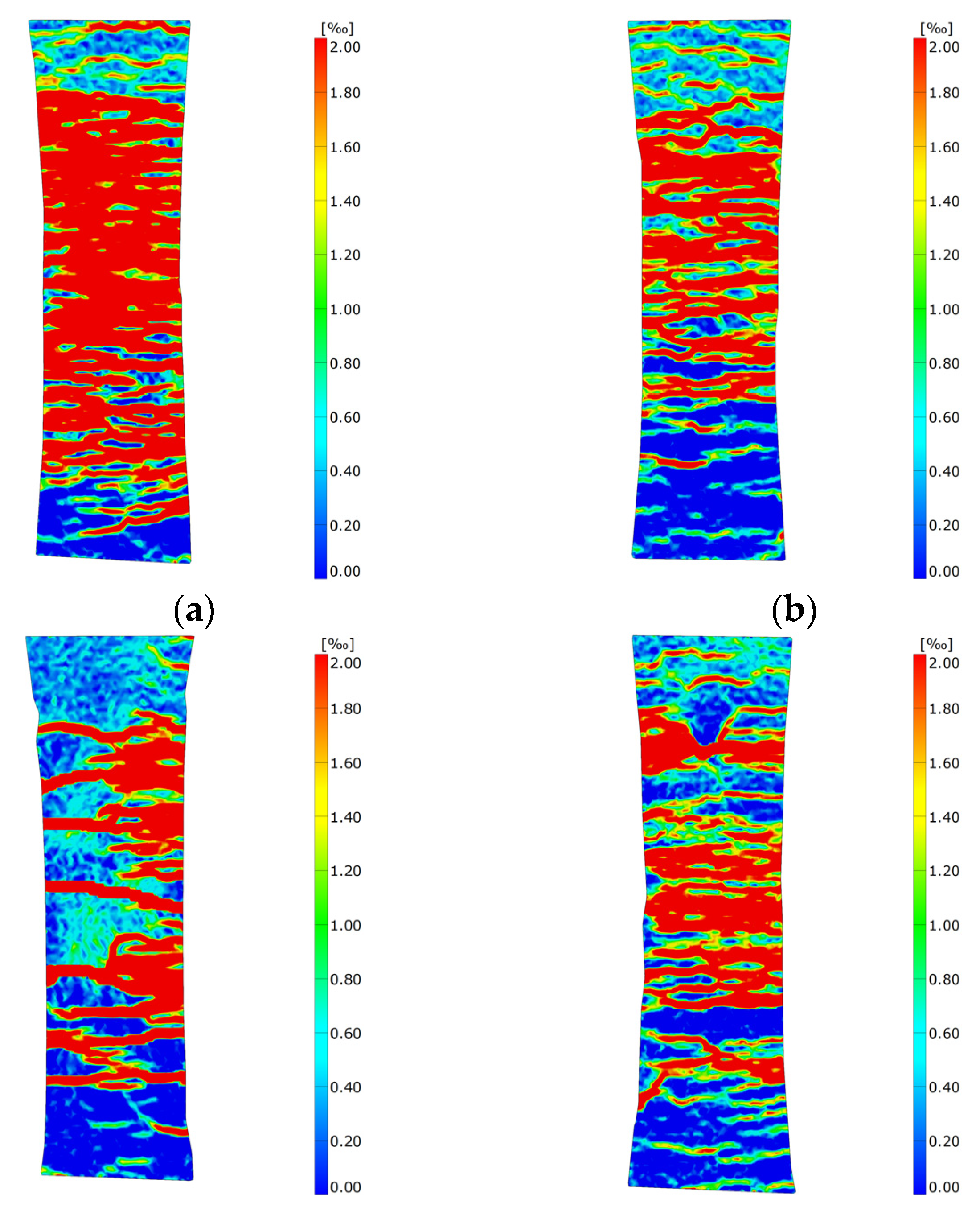
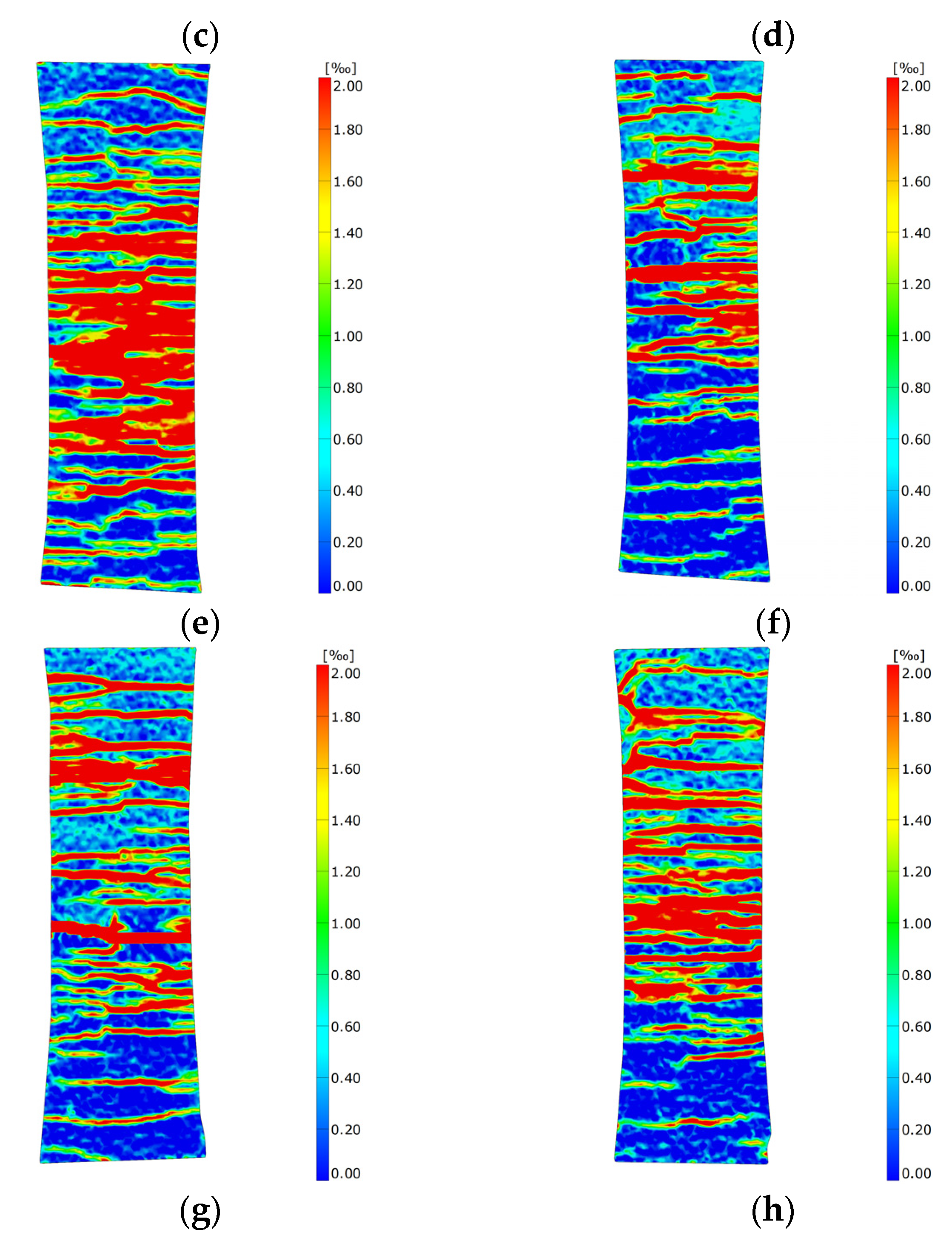
DIC data for two different levels of stress in the specimens are presented below. In Figure 8a–h, the presented results correspond with a stress level of 5 MPa (linear behavior), and the red color is the highest presented strain of 0.3‰, while blue color is the state without any strain (0.00‰). The strain state immediately before failure of specimens is provided in Figure 9a–h, in which the red color is the highest presented strain of 2.0‰, while the blue color, like in Figure 8, is the state without any strain (0.00‰).
By observing specimens from “life periods” 2 and 3, Figure 8c–h show that the older the specimen, the higher the strain. Thus, the later the specimen is loaded, the more significant the state of observed strain. This is caused by the influence of concrete shrinkage on CSFRC behavior as explained in Section 3.4. Namely, the later the specimen is tested, the higher the prevented concrete shrinkage strain, ε s h , p . ε s h , p represents the beginning, or zero strain state, of the specimen immediately before it is loaded during testing. Since ε s h , p is higher in the specimens tested at the later age (“life period” 3—Figure 8g,h) than in those tested at the earlier age (“life period” 2—Figure 8c–f) they will experience faster strain development for the same magnitude of external load.
Figure 8a,b show the strain development of the specimens from “life period” 1. However, these results cannot be compared with those from “life periods” 2 and 3 (Figure 8c–h), because in “life period” 1 there are two different processes taking place, namely hardening and shrinkage. Since the concrete is still “soft” in this “life period”, the state of strain is more pronounced than it would be in “life periods” 2 for the same load level (Figure 8a–c). The specimen is slightly “softer” at 9 days old (Figure 8a) than at 14 days of age (Figure 8b). This fact causes the strain state to be slightly more pronounced in Figure 8a than in Figure 8b.
By looking at Figure 9a–h, we can see, similarly to the previous analysis, the existence of the three “life periods”. The CSFRC specimens in “life period” 1 (Figure 9a,b) are the most damaged, because they have not yet reached full tensile strength, and the concrete tensile strength in this area is also relatively low. This is especially visible in Figure 9a, where due to the low concrete tensile strength, the CSFRC damage is so significant that the carbon fiber bearing capacity is fully utilized. Due to such significant CSFRC damage, the energy dissipation capacity is huge, and this significantly contributes to the high-ductile behavior observed in Figure 6a. At the age of 14 days (Figure 9b), the CSFRC and concrete tensile strength are slightly higher such that the concrete contributes more to the bearing capacity of the specimen, resulting in slightly lower utilization of the carbon fiber bearing capacity. The lower degree of damage degree also means lower ductility (Figure 6b).
In “life period” 1, the CSFRC hardening process is completed, so in “life periods” 2 and 3, it is possible to estimate the influence of concrete shrinkage, and the actual prevented concrete shrinkage strain, on the nonlinear ductile behavior of the specimens as well as on their failure. It can be observed that the specimens at 21, 28, 35, and 49 days of age (Figure 9c–f) are more damaged than specimens at the age of 70 and 91 days (Figure 9g,h). It was earlier determined that the specimen at the age of 49 days is in a state of transition from period 2 to period 3, so it can have features of both “life periods”; for this reason, it will be excluded from further comparisons of these two periods. The specimens from “life period” 2 are more damaged, so they have the higher average ultimate tensile strain (Figure 6c–e), higher energy dissipation capacity, and hence higher ductility than specimens from “life period” 3 (Figure 6g,h). The previously explained concrete shrinkage influence on the CSFRC behavior can be used to explain these behavior differences. Namely, if the prevented shrinkage strain of CSFRC, ε s h , p , is high (or too high), then it can cause cracking to appear more quickly after loading (or it can cause the appearance of micro-cracks before loading). It has already been concluded that the earlier the specimens are loaded, the lower the prevented shrinkage strain, ε s h , p . In accordance with that, it is possible that prevented shrinkage strain, ε s h , p , can cause micro-cracks in the specimen before loading, and since these cracks occur before the testing time and the time of taking DIC pictures, these cracks will not be observed during the testing process. On this basis, it can be concluded that the concrete shrinkage, which is actually the prevented shrinkage strain of CSFRC, decreases the damage capacity of the specimens and, consequently, their energy dissipation capacity and ductility. From Figure 9c–e, there are not (many) obvious micro-cracks in the specimens before testing, so most of the cracks were recorded by DIC, and hence the specimens show a high level of damage and ductile behavior (Figure 6c–e). Unlike the specimens of 21, 28, and 35 days, the specimens tested at the age of 70 and 91 days (Figure 9g,h) experienced cracking as a consequence of prevented shrinkage strain, ε s h , p , before testing, so these cracks were not recorded by DIC and, as a result, these specimens show a lower degree of damage (Figure 9g,h), which in turn results in lower energy dissipation capacity and, consequently, slightly lower ductility (Figure 6g,h).

4. Conclusions

Based on the previously described analysis and results, the CSFRC “lifespan” can be divided into three periods: childhood (1), the best life period (2), and the old age period (3). In the first life period, the tensile strength of CSFRC is much higher than that of normal concrete at the age of 28 days and almost twice that of UHPC, which enables significantly earlier utilization. However, it is important to consider that CSFRC in this life period is prone to significant damage, and its serviceability may be endangered. The second life period begins at the age of 21 days and lasts for around 30 days. In this period, CSFRC presents the best features and has significantly high ductile behavior. Upon further aging, CSFRC passes from the second to third life period, and this leads to the loss of some features, such as a decrease in the ductility.
  • The hardening process is faster for CSFRC than normal concrete or UHPC, and CSFRC reaches full tensile strength at the age of 21 days.
  • Reinforcing concrete with carbon fibers contributes to the increase in elasticity modulus and prolongs the time of its development up to 21 days of age. Carbon fibers also prevent subsequent degradation of the elasticity modulus, e.g., between the 21st and 91st day of age.
  • The temporal development of CSFRC tensile strength, first crack strength, ultimate tensile strain, and elasticity modulus can be well estimated using the modified fib Model Code 2010 equations proposed in this work.
  • The tensile behavior of CSFRC significantly differs from that of unreinforced concrete, showing similarities with steel behavior. Hence, it can be estimated using a bi-linear diagram through three points, especially in the second life period. However, in the first and third life periods, the bi-linear diagram through three points can underestimate damage in the CSFRC in the region between the stress level of the first nonlinearities and achieving the full tensile strength of CSFRC; hence, in these life periods, the four-point stress–strain curve is proposed as a material model.
  • Concrete shrinkage has a significant influence on the CSFRC behavior over time, decreasing the ductility and energy dissipation capacity. In the linear region, it causes faster strain development, while in the nonlinear region, it reduces the damage capacity.
  • Concrete shrinkage can also have a positive influence on CSFRC behavior, contributing to increased tensile strength and first crack strength in “life periods” 2 and 3.

Author Contributions

Conceptualization, A.D.; methodology, A.D. and P.L.; validation, A.D.; investigation, A.D.; writing—original draft preparation, A.D.; writing—review and editing, A.D., P.L., O.F. and G.Š.; visualization, A.D.; supervision, O.F. and G.Š. All authors have read and agreed to the published version of the manuscript.

Funding

Open Access funding enabled and organized by Project DEAL: This research was funded by the German Research Foundation DFG as a part of the “Priority Programme SPP 2020: Cycle deterioration of High-Performance Concrete in an experimental-virtual lab” (Grant Numbers VO 829/13-1, FI 1720/7-1, GF1664/13-1, PE 1464/6-1).

Institutional Review Board Statement

Not applicable.

Informed Consent Statement

Not applicable.

Data Availability Statement

Raw data are available from the authors upon request.

Acknowledgments

The researchers express their gratitude to everyone involved in the priority program SPP 2020, as the working atmosphere between the groups is created by fruitful collaboration.

Conflicts of Interest

The authors declare no conflict of interest.

References

  1. Hamad, H.M.; Shi, J.; Al Jawahery, M.S.; Majdi, A.; Yousif, S.T.; Kaplan, G. Application of natural fibers in cement concrete: A critical review. Mater. Today Commun. 2023, 35, 105833. [Google Scholar] [CrossRef]
  2. Ahmad Firas, S.; Gilles, F.; Le Roy, R. Bond between carbon fiber-reinforced polymer (CFRP) bars and ultra high performance fiber reinforced concrete (UHPFRC): Experimental study. Constr. Build. Mater. 2011, 25, 479–485. [Google Scholar] [CrossRef]
  3. Serdar Camli, U.; Binici, B. Strength of carbon fiber reinforced polymers bonded to concrete and masonry. Constr. Build. Mater. 2007, 21, 1431–1446. [Google Scholar] [CrossRef]
  4. Li, R.; Sang Cho, Y.; Zhang, S. Punching shear behavior of concrete flat plate slab reinforced with carbon fiber reinforced polymer rods. Compos. B Eng. 2007, 38, 712–719. [Google Scholar] [CrossRef]
  5. Calvet, V.; Valcuende, M.; Benlloch, J.; Canoves, J. Influence of moderate temperatures on the bond between carbon fiber reinforced polymer bars (CFRP) and concrete. Constr. Build. Mater. 2015, 94, 589–604. [Google Scholar] [CrossRef]
  6. Jing, M.; Grünberg, G. Mechanical analysis of reinforced concrete box beam strengthened with carbon fiber sheets under combined actions. Compos. Struct. 2006, 73, 488–494. [Google Scholar] [CrossRef]
  7. Jing, M.; Raongjant, W.; Li, Z. Torsional strengthening of reinforced concrete box beams using carbon fiber reinforced polymer. Compos. Struct. 2007, 78, 264–270. [Google Scholar] [CrossRef]
  8. Lee, W.T.; Chiou, Y.J.; Shih, M.H. Reinforced concrete beam-column joint strengthened with carbon fiber reinforced polymer. Compos. Struct. 2010, 92, 48–60. [Google Scholar] [CrossRef]
  9. Lee, H.S.; Kage, T.; Noguchi, T.; Tomosawa, F. An experimental study on the fetrofitting effects of reinforced concrete columns damaged by rebar corrosion strengthened with carbon fiber sheets. Cem. Concr. Res. 2003, 33, 563–570. [Google Scholar] [CrossRef]
  10. Piekarczyk, J.; Piekarczyk, W.; Blazewicz, S. Compression strength of concrete cylinders reinforced with carbon fiber laminate. Constr. Build. Mater. 2011, 25, 2365–2369. [Google Scholar] [CrossRef]
  11. Hambach, M.; Möller, H.; Neumann, T.; Volkmer, D. Portland cement paste with aligned carbon fibers exhibiting exceptionally high flexural strength (>100 MPa). Cem. Concr. Res. 2016, 89, 80–86. [Google Scholar] [CrossRef]
  12. Lauff, P.; Pugacheva, P.; Rutzen, M.; Weiß, U.; Fischer, O.; Volkmer, D.; Peter, M.A.; Große, C.U. Evaluation of the Behavior of Carbon Short Fiber Reinforced Concrete (CSFRC) Based on a Multi-Sensory Experimental investigation and a Numerical Multiscale Approach. Materials 2021, 14, 7005. [Google Scholar] [CrossRef] [PubMed]
  13. Rutzen, M.; Lauff, P.; Niedermeier, R.; Fischer, O.; Raith, M.; Grosse, C.U.; Weiss, U.; Peter, M.A.; Volkmer, D. Influence of fiber alignment on pseudoductility and microcracking in a cementitious carbon fiber composite material. Mater. Struct. 2021, 54, 58. [Google Scholar] [CrossRef]
  14. Rutzen, M.; Schulz, M.; Mossburger-Will, J.; Lauff, P.; Fischer, O.; Volkmer, D. 3D printing as an automated manufacturing method for a carbon fiber-reinforced cementitious composite with outstanding flexural strength (105 N/mm2). Mater. Struct. 2021, 54, 234. [Google Scholar] [CrossRef]
  15. Nerella, V.N.; Ogura, H.; Mechtcherine, V. Incorporating reinforcement into digital concrete construction. In Proceedings of the IASS Symposium 2018: Creativity in Structural Design, Boston, MA, USA, 16–20 July 2018. [Google Scholar]
  16. Ivorra, S.; Garces, P.; Catala, G.; Andion, L.G.; Zornoza, E. Effect of silica fume particle size on mechanical properties of short carbon fiber reinforced concrete. Mater. Des. 2010, 31, 1553–1558. [Google Scholar] [CrossRef]
  17. Chen, P.W.; Chung, D.D.L. Low-drying-shrinkage concrete containing carbon fibers. Compos. B Eng. 1996, 27B, 269–274. [Google Scholar] [CrossRef]
  18. Lura, P.; Jensen, O.M.; van Breugel, K. Autogenous shrinkage in high-performance cement paste: An evaluation of basic mechanisms. Cem. Concr. Res. 2003, 33, 223–232. [Google Scholar] [CrossRef]
  19. Wu, L.; Farzadnia, N.; Shi, C.; Zhang, Z.; Wang, H. Autogenous shrinkage of high performance concrete: A review. Constr. Build. Mater. 2017, 149, 62–75. [Google Scholar] [CrossRef]
  20. Yang, L.; Shi, C.; Wu, Z. Mitigation techniques for autogenous shrinkage of ultra-high-performance concrete—A review. Compos. B Eng. 2019, 178, 107456. [Google Scholar] [CrossRef]
  21. Mazoli, A.; Monosi, S.; Plescia, E.S. Evaluation of the early-age-shrinkage of Fiber Reinforced Concrete (FRC) using image analysis methods. Constr. Build. Mater. 2015, 101, 596–601. [Google Scholar] [CrossRef]
  22. Bontea, D.M.; Chung, D.D.L.; Lee, G.C. Damage in carbon fiber-reinforced concrete, monitored by electrical resistance measurement. Cem. Concr. Res. 2000, 30, 651–659. [Google Scholar] [CrossRef]
  23. Chen, P.W.; Chung, D.D.L. Carbon fiber reinforced concrete for smart structures capable of non-destructive flaw detection. Smart. Mater. Struct. 1993, 2, 22–30. [Google Scholar] [CrossRef]
  24. Chen, B.; Liu, J. Damage in carbon fiber-reinforced concrete, monitored by both electrical resistance measurement and acoustic emission analysis. Constr. Build. Mater. 2008, 22, 2196–2201. [Google Scholar] [CrossRef]
  25. Chung, D.D.L. Cement reinforced with short carbon fibers: A multifunctional material. Compos. B Eng. 2000, 31, 511–526. [Google Scholar] [CrossRef]
  26. Shi, Z.Q.; Chung, D.D.L. Carbon fiber-reinforced concrete for traffic monitoring and weighing in motion. Cem. Concr. Res. 1999, 29, 435–439. [Google Scholar] [CrossRef]
  27. Sun, M.; Liu, Q.; Li, Z.; Hu, Y. A study of piezoelectric properties of carbon fiber reinforced concrete and plain cement paste during dynamic loading. Cem. Concr. Res. 2000, 30, 1593–1595. [Google Scholar] [CrossRef]
  28. Sun, M.; Li, Z.; Mao, Q.; Shen, D. Study on the hole conduction phenomenon in carbon fiber-reinforced concrete. Cem. Concr. Res. 1998, 28, 549–554. [Google Scholar] [CrossRef]
  29. Sun, M.; Li, Z.; Mao, Q.; Shen, D. Thermoelectric percolation phenomena in carbon fiber-reinforced concrete. Cem. Concr. Res. 1998, 28, 1707–1712. [Google Scholar] [CrossRef]
  30. Wang, W.; Wu, S.; Dai, H. Fatigue behavior and life prediction of carbon fiber reinforced concrete under cyclic flexural loading. Mater. Sci. Eng. A 2006, 434, 347–351. [Google Scholar] [CrossRef]
  31. TUMuenchen. 3D Printing in Concrete. Additive Manufacturing at TUM. Available online: https://www.youtube.com/watch?v=H3aD0VZ3ESU (accessed on 17 March 2021).
  32. Fischer, O.; Volkmer, D.; Lauff, P.; Hambach, M.; Rutzen, M. Zementgebundener Kohlenstofffaserverstärkter Hochleistungswerkstoff (Carbonkurzfaserbeton); Forschungsinitiative Zukunft Bau, Band F 3178; Fraunhofer IRB Verlag: Stuttgart, Germany, 2019. [Google Scholar]
  33. Lauff, P.; Fischer, O. Effizienter Ultrahochleistungsbeton mit innovativer trajektorienorientierter „Bewehrung“. Ce Pap. 2019, 3, 82–88. [Google Scholar] [CrossRef]
  34. Oluokun, F.A.; Burdette, E.G.; Deatherage, J.H. Rates of Development of Physical Properties of Concrete at Early Ages. Transp. Res. Rec. 1990, 1284, 16–22. [Google Scholar]
  35. Obayes, O.; Gad, E.; Pokharel, T.; Lee, J.; Abdouka, K. Evaluation of Concrete Material Properties at Early Age. CivilEng 2020, 1, 326–350. [Google Scholar] [CrossRef]
  36. International Federation for Structural Concrete (fib). Model Code 2010; International Federation for Structral Concrete: Lausanne, Switzerland, 2010. [Google Scholar]
  37. Kusumawardaningsih, Y.; Fehling, E.; Ismail, M.; Aboubakr, A.A.M. Tensile strength behaviour of UHPC and UHPFRC. Procedia Eng. 2015, 125, 1081–1086. [Google Scholar] [CrossRef] [Green Version]
  38. Fladr, J.; Bily, P.; Trtik, T. Analysis of the influence of supplementary cementitious materials used in UHPC on modulus of elasticity. IOP Conf. Ser. Mater. Sci. Eng. 2019, 522, 012010. [Google Scholar] [CrossRef]
  39. Kocab, D.; Kucharczykova, B.; Misak, P.; Zitt, P.; Kralikova, M. Development of the Elastic Modulus of Concrete under Different Curing Conditions. Procedia Eng. 2017, 195, 96–101. [Google Scholar] [CrossRef]
  40. Van Breugel, K.; Van Tuan, N. Autogenous Shrinkage of HPC and Ways to Mitigate it. Key Eng. Mater. 2014, 629–630, 3–20. [Google Scholar] [CrossRef] [Green Version]
  41. Džolan, A.; Galić, M.; Harapin, A. Model for the Simulation of the Time-Dependent State in RC Elements. Appl. Sci. 2022, 12, 1501. [Google Scholar] [CrossRef]
  42. Džolan, A.; Kožul, M.; Harapin, A.; Ćubela, D. Analysis of the concrete shrinkage effects on the real behavior of the spatial concrete and reinforced concrete structures using the thermal analogy. Eng. Comput. 2020, 37, 1451–1472. [Google Scholar] [CrossRef]
  43. Gribniak, V.; Kaklauskas, G.; Kliukas, R.; Jakubovskis, R.J. Shrinkage effect on short-term deformation behavior of reinforced concrete—When it should not be neglected. Mater. Des. 2013, 51, 1060–1070. [Google Scholar] [CrossRef]
Figure 1. Shape and dimensions (measurement unit is mm) of the specimens (a); printing process (b); specimen surface with glued strain gauges (c); specimen surface prepared for DIC (d).
Applsci 13 07081 g001
Figure 2. Temporal development of tensile strength.
Applsci 13 07081 g002
Figure 3. Temporal development of the first crack strength.
Applsci 13 07081 g003
Figure 4. Temporal development of the ultimate tensile strain.
Applsci 13 07081 g004
Figure 5. Temporal development of elasticity modulus.
Applsci 13 07081 g005
Figure 6. Stress–strain curves of specimens at the ages of 9 (a), 14 (b), 21 (c), 28 (d), 35 (e), 49 (f), 70 (g), and 91 days (h).
Applsci 13 07081 g006
Figure 7. Concrete shrinkage development in unreinforced concrete element (a) and a CSFRC element (b); total strain in a CSFRC element (c).
Applsci 13 07081 g007
Figure 8. View of the strain state at the stress level of 5 MPa at the following ages: 9 (a), 14 (b), 21 (c), 28 (d), 35 (e), 49 (f), 70 (g), and 91 days (h).
Applsci 13 07081 g008aApplsci 13 07081 g008b
Figure 9. View of the strain immediately before failure at the following ages: 9 (a), 14 (b), 21 (c), 28 (d), 35 (e), 49 (f), 70 (g), and 91 days (h).
Applsci 13 07081 g009aApplsci 13 07081 g009b
Table 1. List of raw materials.
ComponentType of Componentwt%
CementHolcim Sulfo 52.5 R34.70
Silica fumeSika Silicol P21.70
Quartz powderSF50021.70
Quartz sandH337.70
Water-----11.70
SuperplasticizerBASF ACE 4602.50
Carbon fibersZoltek (Toray) PX35, 3 mm1.00 (vol%)
Table 2. Experimental results—tensile strength and elasticity modulus.
Specimen AgeSpecimen NameTensile Strength [MPa]Average Tensile Strength [MPa]Elasticity Modulus [GPa]Average Elasticity Modulus [GPa]
9S5513.5713.4434.7534.91
S6413.3335.50
S6513.4134.48
14S3913.4213.7338.6036.50
S4513.5735.30
S5414.2035.60
21S4114.6614.7336.4537.17
S4714.4836.45
S6015.0538.60
28S3714.6414.9232.6034.55
S4415.0135.00
S5715.1136.05
35S4614.4715.0636.2036.95
S4815.0337.70
S6115.6736.95
49S5014.3014.8437.9536.40
S5214.7035.30
S6615.5135.95
70S5315.7515.3937.2037.18
S5614.7238.20
S5915.6936.15
91S5815.6815.2435.0038.23
S6214.7737.70
S6315.2842.00
Table 3. Experimental results—first crack strength and ultimate tensile strain.
Specimen AgeSpecimen NameFirst Crack Strength [MPa]Average First Crack Strength [MPa]Ultimate Strain [‰]Average Ultimate Strain [‰]
9S557.007.573.563.46
S648.193.00
S657.533.83
14S399.757.201.171.47
S455.851.50
S546.001.73
21S418.407.902.802.65
S477.802.25
S607.502.90
28S378.308.873.422.42
S449.202.28
S579.111.56
35S468.7010.221.882.79
S4810.303.02
S6111.653.47
49S5010.2510.771.501.90
S5211.901.50
S6610.152.70
70S5310.1010.552.201.84
S5611.351.57
S5910.201.76
91S5811.5611.032.702.00
S6211.182.45
S6310.350.86
Disclaimer/Publisher’s Note: The statements, opinions and data contained in all publications are solely those of the individual author(s) and contributor(s) and not of MDPI and/or the editor(s). MDPI and/or the editor(s) disclaim responsibility for any injury to people or property resulting from any ideas, methods, instructions or products referred to in the content.