
Comparison of Different Configurations for Shoreline Pond Electrode Station for HVDC Transmission Systems—Part I: Electric Field Study for Frames of Linear Electrode Arrangement Based on a Simplified Analytical Model

 , , ,
, , ,  and
and
Abstract
:Featured Application
Abstract
1. Introduction
- Marginal positioning of the electrode stations: In both areas, but especially in the area of Stachtoroi, the necessary lengths of the electrode stations can only be ensured marginally by reaching the shores, requiring dredging of the pond under construction, etc.
- Exchange of water within the pond: The construction of a rubble-mound dam, permeable to water through a suitable layering of rubble, does not ensure the complete exchange of water within the pond, due to the small waves in the Argosaronic gulf and the small tidal effect, in contrast to the Muskrat Falls Project [5,6].
- Dam height: The initial height of the dam was significantly shorter than the expected maximum wave height, especially in the area of Korakia, so this naturally leads to an increase in the height of the dam and, by extension, to an increase in its other parameters.
2. Analytical Methodology for the Calculation of Electric Field Strength
- Determination of the minimum number of electrodes and layout configuration: the minimum number of necessary electrodes Nmin_el is determined, based on the maximum nominal current Itot flowing through the electrode station as follows:
- Calculation of electric field strength per electrode: The determination is made by combining two models proposed in [2]. In particular, for the near-field, a linear current source is considered (method “C” in [2]). Figure 1 presents a simplified structure, taking into account a zone for the effective height L in cylindrical coordinates. On the “left” part, the electrode is positioned at a distance dr1 from the dam, while the depth of the dam is td. Hence, the exterior radius of the dam is dr2 = dr1 + td. On the “right” part, the electrode is at a distance dr3 from the soil, provided the respective depth is ensured. The angle formed with the ground plane is θg.
- The electromagnetic field theory requires the continuity of the tangential electric field strength, as well as of the vertical current density, on the dividing surfaces.
- The non-radial currents on the surfaces r = dr1, r = dr1, and r = dr3 are ignored.
- The infinite layer of seawater–dam–soil has a constant active thickness L, while in reality, it grows significantly, e.g., at short distances, it has a thickness of the order of meters, as much as the height of the electrode, while at long distances, it is tens or hundreds of meters (making it too conservative and unsuitable for the far-field).
- The seawater resistivity ρw, dam resistivity ρd, and soil resistivity ρs are considered constant, while in reality, they change (especially that of the soil). If the most unfavourable values are taken (e.g., considering the ground resistivity as infinite), the most conservative result is obtained.
- The materials of soil, dam, and seawater segments do not form uniform surfaces; their shape varies in different directions, as shown in Figure 1. However, it is a quite satisfactory approach.
- 6.
- The soil does not form a wedge and the water is also not a uniform wedge, with its shape varying in different directions. Nonetheless, this approach is better than those of IEC TS 62344: 2013 and CIGRE B4.61 675: 2017.
- 7.
- The electrodes are situated in areas that are protected, such as a shore or a cave, while the exposed side of the sea is limited to an angle φ (rad) smaller than π rad. The analysis can be improved using the multiplier π/φ to the calculated distance of the remote earth.
- 8.
- The actual inclination varies, both axially and radially. The analysis can be made, on the safe side, by considering different inclinations of the seabed or always considering the worst-case scenario, e.g., assuming the average inclination, not as the initial inclination from the coast but as the distance of interest, which is usually relatively small.
- Configuration of electrode frames: First, the electrodes are placed at suitable distances forming a frame, e.g., in Figure 3, each frame is made up of a number of electrodes Νel_frame (13 in this case), with a diameter equal to del (twice the radius rel), which are vertically placed in series with each other at a distance ℓp (measuring from each bar centre). The upper edge of the frame/electrodes is at depth hu, the middle of the frame/electrodes is at depth hm, the lower edge of the frame/electrodes is at depth hd, while the seabed depth is hsb. Therefore, the water zone of the near-field intensity calculation method L has a height equal to the length of the electrodes Lel, while the total frame length ℓf and the respective vertical suspension depths are calculated as follows:
- Formation of an electrode station of frames: The electrode frames are placed in appropriate positions, forming the electrode station. Figure 4 shows the basic form, due to the previous experience in near-shore electrodes [1,2,5,6,7,8,9,10], where the frame is similar to Figure 3 and the respective frames are placed in series, forming an imaginary axis parallel to the longitudinal axis of the breakwater from the inner/protected side. Listed are:
- ▪
- The width of the dam td on the xOx/ axis;
- ▪
- The distance of the imaginary axis of the electrode station from the axis of the dam dr1 on the axis xOx/;
- ▪
- The frame length ℓf;
- ▪
- The estimated width of the critical frame zone dfv, vertical to the dam (along the xOx/ axis), resulting from single-frame simulations;
- ▪
- The distance between consecutive frames on the dam, estimated to ensure the critical zone for diver drops for repairs sc (on yOy/), resulting from single-frame simulations;
- ▪
- The width dstv of the electrode station critical zone, vertical to the dam (on the xOx/ axis), resulting from the electrode station simulations;
- ▪
- The length of the electrode station critical zone ℓcbd on the dam and below the centre of the dam (on the yOy/ axis), resulting from the electrode station simulations;
- ▪
- The length of the electrode station critical zone ℓcud on the dam and above the centre of the dam (on the yOy/ axis), resulting from the electrode station simulations.
- Calculation of the electrode station electric field strength: Initially, the area of concern is the water surface, which is arranged in a suitable canvas of two-dimensional Cartesian coordinates, upon which the electrode is set a particular position. Upon this canvas, of steps dstep_x and dstep_y, the electric field strength is measured. Practically, Figure 4 includes the entire respective area, extending on the Ox semi-axis up to 150 km, while on the yOy’ axis up to a few kilometres. The aforementioned steps are not constant, but vary, since the canvas grows gradually sparser while moving away from the electrode. The calculation of the radial electric field strength Er is then determined, employing the applied method. In this, the corresponding electrode is used as the point of reference and the electric current is the product of the electric current density Jfu_lo or Jmt, and the respective peripheral surface of the electrode Sp_el. The electric field strength of the k-th electrode is analysed in its components Εx−k and Εy−k, on xOx’ and yOy’ axes (as in Figure 5), utilising the coordinates (xk, yk) of the electrode (x,y) of the point of interest (canvas points) and the corresponding distance rk:
- Determination of areas ensuring electric field strength and voltage limits according to IEC TS 62544:2013 and CIGRE B4.61 675:2017: In order for the operating conditions of the electrode station to be safe—under any operating conditions—whether it concerns the specialised maintenance staff, or people and living beings, in the areas of direct access, limits are set for the electric field strength, touch voltage, step voltage, metal-to-metal touch voltage, and absolute voltage with respect to remote earth. In particular, taking the most unfavourable limits from the general guidelines of IEC TS 62544:2013 [27] (p. 32) and CIGRE B4.61 675:2017 [1] (p. 65), as well as recommendations about the pipe-to-soil potential difference based on the applied provisions of cathodic protection [35], the necessary conditions that must be met (as they are also summarised in §2.5. of [2]) are as follows:
- Electric field strength (potential gradient) for continuous operating conditions in water should be smaller than or equal to 1.25 V/m (for marine mammals, while it could be up to 2.5 V/m when concerning humans).
- Electric field strength (potential gradient) for transient operating conditions in water should be smaller than or equal to 15 V/m.
- Potential difference between metal equipment and soil for continuous operating conditions should be smaller than or equal to 4 V. Practically, on the safe side, it could be taken as the corresponding limit for the absolute potential with respect to remote earth.
- Metal-to-metal touch voltage, touch voltage, and step voltage for continuous operating conditions should be smaller than or equal to 5 V.
- Metal-to-metal touch voltage, touch voltage, and step voltage for transient operating conditions should be smaller than or equal to 30 V.
3. Electrode Station Configuration
3.1. General Data
- At monopolar steady-state operation, each pole has a nominal power of 500 MW at a nominal voltage of 500 kV. Hence, the nominal current of the station is at 1000 A.
- The maximum transient current of the station reaches a peak value of 12,800 A, with a duration of 0.5 s during fault clearing.
- The fully reversible electrode to be used is a high-silicon iron, tubular, type 4884 SZ, Centertec Z series, by ANOTEC, conforming to ASTM A518 G3, with a connection resistance of 1 mΩ, weight of 143 kg, diameter of 122 mm (=2∙rel), length of 2130 mm (=Lel), and maximum electric current density up to 20 A/m2 for successful reversible operation of the electrode, according to the manufacturer [33].
- The electrodes are suspended vertically, in order to obtain the largest possible water zone, when analysing the near-electric field and also because it is the structurally easier suspension mode in the case of concrete breakwaters with vertical walls.
- In the area of Stachtoroi (Argosaronic Gulf, Attica), the angle θg on the plan view of Figure 1 is taken to be equal to 210° based on the location of the electrode station (see Figure 11 in [2]), while the respective water angle θw of Figure 2 is equal to 0.272° (see the worst-case scenario for the Aegina region of Table 1 in [2]). The available dam length is about 50 m.
- In the area of Korakia (Crete), the angle θg on the plan view of Figure 1 is taken to be equal to 248° based on the location of the electrode station (see Figure 12 in [2]), while the respective water angle θw of Figure 2 is equal to 2.29° (see the worst-case scenario/far region of Table 1 in [2]). The available dam length is about 70 m.
- The seawater electrical resistivity takes a value of 0.25 Ω∙m, despite the fact that its value ranges from 0.167 to 0.212 Ω∙m for both areas. In this way, the uncertainty that can arise from salinity reduction, due to freshwater inflow to seawater, is addressed, especially in the Korakia region where there are also two small dry rivers. In addition, the electrodes will always be placed at a greater depth than the breaking wave water can reach (which has a significantly greater electrical resistivity equal to 2.00 Ω∙m).
- For reasons of reliability, the number of linearly positioned frames Nframe is 5, adding an extra one as reserve. Therefore, the total number of electrodes required Nmin_el is 67 as a result of the application of Equation (1), assuming a total electric current, Ιtot_st, of 1100 A at steady state and under overload conditions. Hence, for each frame, the necessary electrodes, Nel_frame, are 13, amounting to a total of 78 (including those in the reserve). Considering the increment factor β (=6.1%) [2] and implementing Equations (2) and (3), the final current density values Jfu_lo_st (under full-load conditions) and Jmt_st (under periodic maintenance) result as equal to 18.33 A/m2 and 22.00 A/m2, respectively. In the transient state, for a current Itot−tr of 12.8 kA, the final current density values Jfu_lo_tr (under full-load conditions) and Jmt_tr (under periodic maintenance) result as equal to 213.28 A/m2 and 255.93 A/m2, respectively.
- The soil electrical resistivity takes the infinitive value, for the sake of simplifying the calculation process, giving more unfavourable/safe results.
- The water zone that corresponds to an arc of angle θg, on the floor plan in Figure 1, is disregarded to simplify the calculation, giving more unfavourable/safe results.
- The breakwater/dam of Figure 1 is disregarded in order to simplify the respective calculation. This affects the electric field strength calculation along with that of the absolute potential, concerning radii within or up to the breakwater. The absolute potential on the dam can be calculated approximately as the product of the respective electric field strength of the seawater and the ratio of the electrical resistivities ρd/ρw.
3.2. Basic Electrode Station Configuration—Straight Frames in Series, Each Placed Parallel to the Longitudinal Axis of the Dam (1st Configuration)
3.3. Second Electrode Station Configuration—Straight Frames in Series, Each Vertically Placed on the Longitudinal Axis of the Dam
- The width of the dam td along the xOx/ axis;
- The distance of the closest electrode from the axis of the dam dr1 along the axis xOx/;
- The total frame length ℓf;
- The estimated width of the critical frame zone dfv vertical to the frame and parallel to the dam along the yOy/ axis, which matches the distance between successive frames, which is estimated to ensure the critical zone for a diver drop for repair, as obtained from single-frame simulations;
- The estimated length of the critical frame zone sc along the frame length, vertical to the dam here, by xOx/, as obtained from single-frame simulations;
- The width dstv of the electrode station critical zone vertical to the dam (along the xOx/ axis), as obtained from the electrode station simulations;
- The length of the electrode station critical zone ℓcbd on the dam and below its centre (along the yOy/ axis), as obtained from the electrode station simulations;
- The length of the electrode station critical zone ℓcud on the dam and above its centre (along the yOy/ axis), as obtained from the electrode station simulations.
3.4. Third Electrode Station Configuration—Straight Frames in Two Overlapping Rows, Each Placed Parallel to the Longitudinal Axis of the Dam in Alignment with Each Other
3.5. Fourth Electrode Station Configuration—Straight Frames in Two Successive Rows, Each Parallel to the Longitudinal Axis and Non-Overlapping on the Vertical Axes of the Dam
3.6. Fifth Electrode Station Configuration—Straight Frames in Two Successive Rows, Each Vertical to the Longitudinal Axis of the Dam and Aligned with Each Other
3.7. Sixth Electrode Station Configuration—Straight Frames in Two Successive Rows, Each Vertical to the Longitudinal Axis of the Dam and Non-Overlapping on the Vertical One
3.8. Seventh Electrode Station Configuration—Straight Frames in Perimeter Placement to the Protective Dam, Adapting to the Outline of the Pond under Construction
- The dam width td;
- The distance of the imaginary axis of each frame from the axis of the dam dr1;
- The total frame length ℓf;
- The widths dOx and dOx/ of the electrode station critical zone vertical to the damn and along the semi-axes Ox and Ox/ from the beginning of the axes, as obtained from the simulations of the electrode station;
- The lengths dOy and dOy/ of the electrode station critical zone parallel to the dam and along the semi-axes Oy and Oy/ from the beginning of the axes, as obtained from the simulations of the electrode station.
3.9. Eighth Electrode Station Configuration—Straight Frames Adapted to a T-Shaped Protective Dam
3.10. Ninth Electrode Station Configuration—Straight Frames Adapted Radially to a Central Base with Guides
- The formed angle θf between successive frames;
- The minimum distance dsc determined through Equation (39);
- The widths dOx and dOx/ of the electrode station critical zone, along the semi-axes Ox and Ox/ from the beginning of the axes, which coincides with the centre of the central base, as obtained from the electrode station simulations;
- The lengths dOy and dOy/ of the electrode station critical zone, along the semi-axes Oy and Oy/ from the beginning of the axes, as obtained from the electrode station simulations.
3.11. 10th Electrode Station Configuration—Straight Frames Adapted Perimetrically to a Central Base
4. Application of the Analytical Methodology for the Calculation of Electric Field Strength in the Electrode Station Various Configurations
4.1. General Remarks
- The electric current density Jst with respect to the peripheral surface;
- The width of the electrode station critical zone dstv, perpendicular to the dam (on the xOx’ axis);
- The length of the electrode station critical zone ℓcud on the dam above the centre of the dam (on the yOy’ axis);
- The length of the electrode station critical zone ℓcbd on the dam below the centre of the dam (on the yOy’ axis);
- The distance sbc between the lowermost rod of the electrode station on the dam, which is connected to the power supply and the nearest point of protection (electrode not connected to power supply for maintenance purposes, dam end);
- The distance suc between the uppermost rod of the electrode station on the dam, which is connected to the power supply and the nearest point of protection (electrode not connected to the power supply for maintenance purposes, dam end);
- The distance of the lowermost rod of the electrode station ℓbc on the dam from the centre of the dam that is connected to the power supply (on yOy’);
- The distance of the uppermost rod of the electrode station ℓuc on the dam from the centre of the dam, connected to the power supply (by yOy’);
- The distance ypr between the nearest point of protection (electrode not connected to power supply for maintenance purposes, dam end) from the centre of the dam that is connected to the power supply (on yOy’);
- The safety margin Dypr in relation to an initial preliminary study of a frame under the same conditions (where negative values indicate a requirement for a greater safety distance);
- The maximum electric field strength of the arrangement Emax.
4.2. Basic Electrode Station Configuration—Straight Frames in Series, Each Placed Parallel to the Longitudinal Axis of the Dam (1st Configuration)
4.3. Second Electrode Station Configuration—Straight Frames in Series, Each Vertically Placed on the Longitudinal Axis of the Dam
- The deviation at the extremes of the array reaches up to 27.3 m, depending on the loading method (especially when the five frames are loaded consecutively). However, in the area of the non-operating frame, the electric field strength rises slightly over 2.5 V/m; therefore, no issues arise (regarding safety) when maintaining the frames, provided the diver has taken the appropriate measures.
- The deviation in the maximum developing electric field strength of the electrode station, compared to a single frame (24.98 V/m against 24.06 V/m, according to Table 10 in [2]), is of the order of 3.8%, which is limited and smaller than that of the first configuration (24.98 V/m versus 26.09 V/m of Table 12 in [2]). However, the necessary distances are observed here.
- The critical zone of the dam extends beyond it by 42.7 m on the outer side (with a crest width of 5 m and a suspension distance of at least 1 m) along the xOx/ axis (perpendicular to the dam), which is slightly better than that of the first configuration (against 44.3 m).
- The critical zone of the dam extends beyond it by 62 m (i.e., 31 m on either side) along the yOy/ axis (parallel to the dam axis) in the coastal area. This is partly due to the fact that the initially estimated required length of the assumed electrode station is 77.0 m (along the yOy/ axis), the corresponding actual required length is 131.5 m (from the results of the superposition model, according to Table 1), while the available length is only 70 m.
- The developed absolute potentials and the corresponding values of the electrode station resistance, with respect to remote earth, are slightly better (22.48 kV, 19.26 Ω) compared to the initial configuration (22.77 kV and 19.5 Ω, according to Table 15 in [2]).
- The deviation at the extremes of the array reaches up to 20.6 m, depending on the loading method (especially when the five frames are loaded consecutively). However, in the area of the non-operating frame, the electric field strength rises slightly over 2.5 V/m; therefore, no issues arise (regarding safety) when maintaining the frames, provided the diver has taken the appropriate measures.
- The deviation in the maximum developing electric field strength of the electrode station compared to a single frame (19.08 V/m against 17.96 V/m, according to Table 11 in [2]) is of the order of 6.2%, which is limited and smaller than that of the first configuration (19.08 V/m versus 19.73 V/m of Table 14 in [2]). However, the necessary distances are observed here.
- The critical zone of the dam extends beyond it by 29.7 m on the outer side (with a crest width of 5 m and a suspension distance of at least 1 m) along the xOx/ axis (perpendicular to the dam), which is practically identical to the value of the first configuration (against 30.3 m).
- The critical zone of the dam extends beyond it by 48 m (i.e., 24 m on either side) along the yOy/ axis (parallel to the dam axis) in the coastal area. This is partly due to the fact that the initially estimated required length of the assumed electrode station is 56.7 m (along the yOy/ axis), the corresponding actual required length is 97.8 m (from the results of the superposition model, according to Table 1), while the available length is only 50 m.
- The developed absolute potentials and the corresponding values of the electrode station resistance, with respect to remote earth, are slightly worse (18.40 kV, 15.76 Ω) compared to the initial configuration (17.30 kV and 14.82 Ω, according to Table 15 in [2]).
4.4. Third Electrode Station Configuration—Straight Frames in Two Overlapping Rows, Each Placed Parallel to the Longitudinal Axis of the Dam in Alignment with Each Other
- The current density Jst with respect to the peripheral surface;
- The width dstv_Ox of the electrode station critical zone, vertical to the dam (along the semi-axis Ox);
- The width dstv_Ox/ of the electrode station critical zone, vertical to the dam (along the semi-axis Ox/);
- The length of the electrode station critical zone ℓcud on the dam above the centre of the dam (on the yOy’ axis);
- The length of the electrode station critical zone ℓcbd on the dam below the centre of the dam (on the yOy’ axis);
- The maximum electric field strength within the area of the frame that is out of operation Eoff;
- The maximum electric field strength of the arrangement Emax.
- The deviation at the extremes of the array (along the yOy/ axis) reaches up to 42.2 m, depending on the loading method (especially when the five frames are loaded consecutively), while, along the xOx/ axis, it reaches up to 49.25 m (especially when the five frames are loaded, except for one of the extreme ones, i.e., 1st, 2nd, 5th, or 6th). However, in the area of the non-operating frame, the electric field strength rises slightly over 2.5 V/m; therefore, no issues arise (regarding safety) when maintaining the frames, provided the diver has taken the appropriate measures.
- The deviation in the maximum developing electric field strength of the electrode station compared to a single frame (26.12 V/m against 24.06 V/m according to Table 10 in [2]) is of the order of 8.6%, practically identical to that of the first configuration (26.12 V/m versus 26.09 V/m of Table 12 in [2]) and worse compared to that of the second configuration (26.12 V/m against 24.98 V/m of Table 1). However, the necessary distances are observed here.
- In Figure 23b, the areas between the electrode frames are marked, where the strength of the electric field is significantly reduced below 1.25 V/m. However, this does not occur in the area of the frame that has been turned off, although it does not exceed the value of 3.0 V/m.
- The critical zone of the dam extends beyond it by 43.3 m (with a crest width of 5 m and a suspension distance of at least 1 m) along the xOx/ axis (perpendicular to the dam), which is slightly better than that of the first configuration (44.3 m).
- The critical zone of the dam extends beyond it by 52.2 m (i.e., 26.1 m on either side) along the yOy/ axis (parallel to the dam axis) in the coastal area. Although the initially estimated required length of the assumed electrode station is 58.0 m (along the yOy/ axis), the corresponding actual required length is 122.2 m (from the results of the superposition model, according to Table 2), while the available length is only 70 m.
- The developed absolute potentials and the corresponding values of the electrode station resistance, with respect to remote earth, are quite worse (26.98 kV, 23.12 Ω) compared to the original configuration (22.77 kV and 19.5 Ω, according to Table 15 in [2]).
- In field behaviour results, there is a similarity in the case of single-frame non-operation, among the 1st, 2nd, 5th, and 6th frames, as well as between the 3rd and 4th, through an appropriate mirroring consideration. However, when determining the absolute potentials, there is a slight variation since the integration is always carried out on the Ox semi-axis.
- The deviation at the extremes of the array (along the yOy/ axis) reaches up to 24.7 m depending on the loading method (especially when the five frames are loaded consecutively), and along the xOx/ axis, it reaches up to 36.18 m (especially when the five frames are loaded, except for one of the extreme ones, i.e., 1st, 2nd, 5th, or 6th). However, in the region of the non-operating frame, the corresponding electric field strength rises slightly over 2.5 V/m; therefore, no issues arise (regarding safety) when maintaining the frames, provided the diver has taken the appropriate measures.
- The deviation in the maximum developing electric field strength of the electrode station compared to a single frame (20.03 V/m against 17.96 V/m, according to Table 11 in [2]) is of the order of 11.5%, which is significantly greater than those in the two previous configurations (19.73 V/m for the first configuration according to Table 14 in [2] and 19.08 V/m for the second configuration according to Table 1), despite the fact that the necessary distances are observed.
- The critical zone of the dam extends beyond it by 30.8 m (with a crest width of 5 m and a suspension distance of at least 1 m) along the xOx/ axis (perpendicular to the dam), which is slightly longer than that of the first configuration (30.3 m).
- The critical zone of the dam extends beyond it by 41.4 m (i.e., 20.7 m on either side) along the yOy/ axis (parallel to the dam axis) in the coastal area. Despite the fact that the initially estimated required length of the assumed electrode station is 42.0 m (along the yOy/ axis), the corresponding actual required length is 91.4 m (from the results of the superposition model, according to Table 2), while the available length is only 50 m.
- The developed absolute potentials and the corresponding values of the electrode station resistance, with respect to remote earth, are quite worse (21.48 kV, 18.40 Ω) compared to the initial configuration (17.30 kV and 14.82 Ω, according to Table 15 in [2]).
- In field behaviour results, there is a similarity in the case of single-frame non-operation, among the 1st, 2nd, 5th, and 6th frames, as well as between the 3rd and 4th, through an appropriate mirroring consideration. However, when determining the absolute potentials, there is a slight variation since the integration is always carried out on the Ox semi-axis.
4.5. Fourth Electrode Station Configuration—Straight Frames in Two Successive Rows, Each Parallel to the Longitudinal Axis and Non-Overlapping on the Vertical Axes of the Dam
- The deviation at the extremes of the array (along the yOy/ axis) reaches up to 29.4 m, depending on the loading method, and along the xOx/axis, it reaches up to 49.0 m (especially when the five frames are loaded, except for the sixth or first). However, in the area of the non-operating frame, the electric field strength is 3.1 V/m (slightly above 2.5 V/m); therefore, no issues arise (regarding safety) when maintaining the frames, provided the diver has taken the appropriate measures.
- The deviation in the maximum developing electric field strength of the electrode station compared to a single frame (26.14 V/m against 24.06 V/m, according to Table 10 in [2]) is of the order of 8.6%. That is, it is slightly higher compared to the first configuration (26.14 V/m against 26.09 V/m, according to Table 12 in [2]), almost identical compared to the third (26.14 V/m against 26.12 V/m according to Table 2), and much higher than that of the second (26.14 V/m against 19.26 V/m according to Table 1).
- In Figure 24b, regions between the electrode frames are shown, where the electric field strength is significantly reduced below 1.25 V/m. However, this does not occur in the area of the frame that is set out of operation, although it does not exceed the value of 3.1 V/m.
- The critical zone of the dam extends beyond it by 43.0 m (with a crest width of 5 m and a suspension distance of at least 1 m) along the xOx/ axis (perpendicular to the dam), which is slightly better than those in the first (44.3 m) and third configurations (43.3 m) and slightly worse than that of the second (42.7 m).
- The critical zone of the dam extends beyond it by 54.8 m (i.e., 27.4 m on either side) along the yOy/ axis (parallel to the dam axis) in the coastal area. Despite the fact that the initially estimated required length of the assumed electrode station is 66.0 m (along the yOy/ axis), the respective actual required length is 124.8 m (from the results of the superposition model in Table 3), while the available length is only 70 m.
- The developed absolute potentials and the corresponding values of the electrode station resistance, with respect to remote earth, are quite worse (26.14 kV, 22.40 Ω) compared to the first (22.77 kV and 19.5 Ω according to Table 15 in [2]) and second configurations (22.48 kV and 19.26 Ω of Table 1) and slightly better than that of the third (26.98 kV and 23.12 Ω of Table 2).
- In field behaviour results, there is a similarity in the case of single-frame non-operation, among the 1st, 2nd, 5th, and 6th frames, as well as between the 3rd and 4th, through an appropriate mirroring consideration. However, when determining the absolute potentials, there is a slight variation since the integration is always performed on the Ox semi-axis.
- The deviation at the extremes of the array (along the yOy/ axis) reaches up to 22.5 m, depending on the loading method, and along the xOx/ axis, it reaches up to 36.95 m (especially when the five frames are loaded, except for the sixth or first). However, in the area of the non-operating frame, the respective electric field strength is slightly above 2.5 V/m; therefore, no issues arise (regarding safety) when maintaining the frames, provided the diver has taken the appropriate measures.
- The deviation in the maximum developing electric field strength of the electrode station compared to a single frame (20.14 V/m against 17.96 V/m, according to Table 11 in [2]) is of the order of 12.14%, which is significantly greater than those in previous configurations (19.73 V/m for the first configuration according to Table 14 in [2], 19.08 V/m for the second one according to Table 1, and 20.03 V/m for the third configuration according to Table 2).
- The critical zone of the dam extends beyond it by 31.0 m (with a crest width of 5 m and a suspension distance of at least 1 m) along the xOx/ axis (perpendicular to the dam), which is slightly longer than the first configuration (30.3 m).
- The critical zone of the dam extends beyond it by 42.54 m (i.e., 21.3 m on either side) along the yOy/ axis (parallel to the dam axis) in the coastal area. Although the initially estimated required length of the assumed electrode station is 47.6 m (along the yOy/ axis), the respective actual required length is 92.54 m (from the results of the superposition model in Table 3), while the available length is only 50 m.
- The developed absolute potentials and the corresponding values of the electrode station resistance, with respect to remote earth, are quite worse (21.58 kV, 18.49 Ω) against the first (17.30 kV and 14.82 Ω according to Table 15 in [2]) and second configurations (18.40 kV and 15.76 Ω of Table 1), and slightly better than those in the third configuration (21.48 kV and 18.40 Ω of Table 2).
- In field behaviour results, there is a similarity in the case of single-frame non-operation, among the 1st, 2nd, 5th, and 6th frames, as well as between the 3rd and 4th, through an appropriate mirroring consideration. However, when determining the absolute potentials, there is a slight variation since the integration is always carried out on the Ox semi-axis.
4.6. Fifth Electrode Station Configuration—Straight Frames in Two Successive Rows, Each Vertical to the Longitudinal Axis of the Dam and Aligned with Each Other
- The deviation at the extremes of the array (along the yOy/ axis) reaches up to 36.2 m, and along the xOx/ axis up to 46.7 m (especially when five frames are loaded, except the 1st, 2nd, 5th, or 6th). However, in the area of the non-operating frame, the respective electric field strength is 3.3 V/m; therefore, no issues arise (regarding safety) when maintaining the frames, provided the diver has taken the appropriate measures.
- The deviation in the maximum developing electric field strength of the electrode station compared to a single frame (26.29 V/m against 24.06 V/m, according to Table 10 in [2]) is of the order of 9.3%, slightly higher compared to the 1st, 3rd, and 4th configurations (26.09 V/m according to Table 12 in [2], 26.12 V/m according to Table 2, and 24.14 V/m according to Table 3, respectively) and much higher compared to the 2nd configuration (19.26 V/m according to Table 1).
- In Figure 25b, regions between the electrode frames are shown, where the electric field strength decreases significantly below 1.25 V/m. However, this does not occur in the area of the frame that is set out of operation, although it does not exceed the value of 3.3 V/m.
- The critical zone of the dam extends beyond it by 40.6 m (with a crest width of 5 m and a suspension distance of at least 1 m) along the xOx/ axis (perpendicular to the dam), which is better than those in all previous configurations (1st→44.3 m, 2nd→42.7 m, 3rd→43.3 m, 4th→43.0 m).
- The critical zone of the dam extends beyond it by 46.7 m (i.e., 23.4 m on either side) along the yOy/ axis (parallel to the dam axis) in the coastal area. Despite the fact that the initially estimated required length of the assumed electrode station is 44.4 m (along the yOy/ axis), the corresponding actual required length is 116.7 m (from the results of the superposition model, according to Table 4), while the available length is only 70 m.
- The developed absolute potentials and the corresponding values of the electrode station resistance, with respect to remote earth, are quite worse (25.71 kV, 22.02 Ω) compared to the first (22.77 kV and 19.5 Ω, according to Table 15 in [2]) and second configurations (22.48 kV and 19.26 Ω of Table 1) but slightly better compared to the third (26.98 kV and 23.12 Ω of Table 2) and fourth (26.14 kV and 22.40 Ω of Table 3).
- In field behaviour results, there is a similarity in the case of single-frame non-operation, among the 1st, 2nd, 5th, and 6th frames, as well as between the 3rd and 4th, through an appropriate mirroring consideration. However, when determining the absolute potentials, there is a slight variation since the integration is always carried out on the Ox semi-axis.
- The deviation at the extremes of the array (along the yOy/ axis) reaches up to 27.17 m and along the xOx/ axis up to 33.91 m (especially when five frames are loaded, except the 1st, 2nd, 5th, or 6th). However, in the area of the non-operating frame, the corresponding electric field strength is 3.3 V/m; therefore, no issues arise (regarding safety) when maintaining the frames, provided the diver has taken the appropriate measures.
- The deviation in the maximum developing electric field strength of the electrode station compared to a single frame (20.16 V/m against 17.96 V/m, according to Table 11 in [2]) is of the order of 12.2%, which is significantly greater than those in the previous configurations (19.73 V/m for the first configuration according to Table 14 in [2], 19.08 V/m for the second configuration according to Table 1, 20.03 V/m for the third configuration according to Table 2, and 20.14 V/m for the fourth configuration according to Table 3).
- The critical zone of the dam extends beyond it by 27.9 m (with a crest width of 5 m and a suspension distance of at least 1 m) along the xOx/ axis (perpendicular to the dam), which is better than those in all previous configurations (1st→30.3 m, 2nd→29.7 m, 3rd→30.8 m, 4th→31.0 m).
- The critical zone of the dam extends beyond it by 36.7 m (i.e., 18.4 m on either side) along the yOy/ axis (parallel to the dam axis) in the coastal area. Although the initially estimated required length of the assumed electrode station is 33.4 m (along the yOy/ axis), the corresponding actual required length is 86.7 m (from the results of the superposition model, in Table 4), while the available length is only 50 m.
- The developed absolute potentials and the corresponding values of the electrode station resistance, with respect to remote earth, are considerably worse (20.35 kV, 17.43 Ω) compared to the first (17.30 kV and 14.82 Ω according to Table 15 in [2]) and second configurations (18.40 kV and 15.76 Ω according to Table 1) and slightly better compared to the third (21.48 kV and 18.40 Ω according to Table 2) and fourth (21.58 kV and 18.49 Ω according to Table 3).
- In field behaviour results, there is a similarity in the case of single-frame non-operation, among the 1st, 2nd, 5th, and 6th frames, as well as between the 3rd and 4th, through an appropriate mirroring consideration. However, when determining the absolute potentials, there is a slight variation since the integration is always carried out on the Ox semi-axis.
4.7. Sixth Electrode Station Configuration—Straight Frames in Two Successive Rows, Each Vertical to the Longitudinal Axis of the Dam and Non-Overlapping on the Vertical One
- The deviation at the extremes of the array (along the yOy/ axis) reaches up to 33.96 m, and along the xOx/ axis up to 46.7 m (especially when loading five frames, except for the first or sixth). However, in the area of the non-operating frame, the corresponding electric field strength is 3.42 V/m; therefore, no issues arise (regarding safety) when maintaining the frames, provided the diver has taken the appropriate measures.
- In Figure 26b, regions between the electrode frames are shown, where the electric field strength decreases significantly below 1.25 V/m. However, this does not occur in the area of the frame that is set out of operation, although it does not exceed the value of 3.42 V/m.
- The deviation in the maximum developing electric field strength of the electrode station compared to a single frame (26.25 V/m against 24.06 V/m, according to Table 10 in [2]) is of the order of 9.1%, slightly higher compared to the 1st, 3rd, and 4th configurations (26.09 V/m according to Table 12 of [2], 26.12 V/m according to Table 2, and 24.14 V/m according to Table 3, respectively), much higher compared to the 2nd (19.26 V/m according to Table 1), and slightly lower compared to the 5th (26.29 V/m according to Table 4).
- The critical zone of the dam extends beyond it by 40.7 m (with a crest width of 5 m and a suspension distance of at least 1 m) along the xOx/ axis (perpendicular to the dam), which is better than those in all previous configurations (1st→44.3 m, 2nd→42.7 m, 3rd→43.3 m, 4th→43.0 m), except for the 5th, with which it is practically identical (40.6 m).
- The critical zone of the dam extends beyond it by 46.78 m (i.e., 23.9 m on either side) along the yOy/ axis (parallel to the dam axis) in the coastal area. Although the initially estimated required length of the assumed electrode station is 48.87 m (along the yOy/ axis), the respective actual required length is 117.78 m (from the results of the superposition model according to Table 4), while the available length is only 70 m. It is practically identical to that of the fifth configuration.
- The developed absolute potentials and the corresponding values of the electrode station resistance, with respect to remote earth, are quite worse (25.94 kV, 22.23 Ω) compared to the first (22.77 kV and 19.5 Ω according to Table 15 in [2]) and second configurations (22.48 kV and 19.26 Ω of Table 1), slightly worse than those in the fifth configuration (25.71 kV, 22.02 Ω), and slightly better compared to the third (26.98 kV and 23.12 Ω of Table 2) and fourth (26.14 kV, 22.40 Ω).
- In field behaviour results, there is a similarity in the case of single-frame non-operation, between the 1st and 6th, the 2nd and 5th, as well as between the 3rd and 4th, through an appropriate mirroring consideration. However, when determining the absolute potentials, there is a slight difference since the integration is always carried out on the Ox semi-axis.
- The deviation at the extremes of the array (on the yOy/ axis) reaches up to 25.56 m, and along the xOx/ axis up to 33.98 m (especially when loading five frames, except for the first or sixth). However, in the area of the non-operating frame, the respective electric field strength is 3.37 V/m; therefore, no issues arise (regarding safety) when maintaining the frames, provided the diver has taken the appropriate measures.
- The deviation in the maximum developing electric field strength of the electrode station compared to a single frame (20.12 V/m against 17.96 V/m, according to Table 11 in [2]) is of the order of 12.0%, which is significant and greater than in most configurations (19.73 V/m for the first according to Table 14 in [2], 19.08 V/m for the second according to Table 1, and 20.03 V/m for the third according to Table 2), while, practically, it is identical to those in the fourth and fifth configurations (20.14 V/m according to Table 3 and 20.16 V/m according to Table 4, respectively).
- The critical zone of the dam extends beyond it by 27.98 m (with a crest width of 5 m and a suspension distance of at least 1 m) along the xOx/ axis (perpendicular to the dam), which is better than those in almost all previous configurations (1st→30.3 m, 2nd→29.7 m, 3rd→30.8 m, 4th→31.0 m) and practically identical to that of the 5th configuration (27.9 m).
- The critical zone of the dam extends beyond it by 37.48 m (i.e., 18.74 m on either side) along the yOy/ axis (parallel to the dam axis) in the coastal area. Although the initially estimated required length of the assumed electrode station is 36.4 m (along the yOy/ axis), the corresponding actual required length is 87.5 m (from the superposition model results in Table 5), while the available length is only 50 m.
- The developed absolute potentials and the corresponding values of the electrode station resistance, with respect to remote earth, are considerably worse (20.51 kV, 17.57 Ω) compared to the first (17.30 kV and 14.82 Ω, according to Table 15 in [2]) and second configurations (18.40 kV and 15.76 Ω, according to Table 1), slightly worse compared to the fifth (20.35 kV and 17.43 Ω according to Table 4), and slightly better compared to the third (21.48 kV and 18.40 Ω according to Table 2) and the fourth configurations (21.58 kV and 18.49 Ω according to Table 3).
- In field behaviour results, there is a similarity in the case of single-frame non-operation, between the 1st and 6th, the 2nd and 5th, as well as between the 3rd and 4th, through an appropriate mirroring consideration. However, when determining the absolute potentials, there is a slight difference since the integration is always conducted on the Ox semi-axis.
4.8. Seventh Electrode Station Configuration—Straight Frames in Perimeter Placement to the Protective Dam, Adapting to the Outline of the Pond under Construction
- The current density Jst with respect to the peripheral surface;
- The width dOx of the electrode station critical zone, vertical to the dam (along the Ox semi-axis), from the beginning of the axes;
- The width dOx/ of the electrode station critical zone, vertical to the dam (along the semi-axis Ox/), from the beginning of the axes;
- The length dOy of the electrode station critical zone, parallel to the dam (along the semi-axis Oy), from the beginning of the axes;
- The length dOy/ of the electrode station critical zone, parallel to the dam (along the semi-axis Oy/), from the beginning of the axes;
- The maximum electric field strength, within the region of the frame that is not operating Eoff;
- The maximum electric field strength of the array Emax.
- The length of the critical zone (along the Oy semi-axis) reaches up to 55.80 m (i.e., there is an inland deviation of 24.8 m) when the station is fully loaded, with the third frame not operating (the distance between the shores, which bridges the complete dam, has a length of 62 m, while, due to its arched form, it reaches 70 m). The length of the critical zone (along the Oy/ semi-axis) reaches up to 62.92 m, that is, there is an inland deviation of 31.92 m when the station is fully loaded, with the sixth frame out of operation. The width of the critical zone (along the Ox/ semi-axis) reaches 74.04 m. That is, there is a zero inland deviation up to 20 m when the station is fully loaded, with the second frame out of operation, due to the formed bay in Korakia (according to Figure 11). So, practically, the zone of influence extends inland laterally up to 32 m (along the yOy/ axis), while along the semi-axis Ox/, it is limited within the sea.
- The width of the critical zone (along the Ox semi-axis) reaches up to 44.60 m when the station is fully loaded, with the fifth frame out of operation. The critical zone, outside the dam, extends by 31.6 m (with crest width of 5 m, with a suspension distance of at least 1 m, and with a distance of extreme frames on the dam along the Ox semi-axis equal to 7 m), which is better than those in all previous configurations.
- The deviation in the maximum developing electric field strength of the electrode station compared to a single frame (24.84 V/m against 24.06 V/m according to Table 10 in [2]) is of the order of 3.2%, which is small and generally smaller than those in all previous configurations.
- In Figure 27b, regions between the electrode frames are shown, where the electric field strength decreases significantly below 1.25 V/m. However, this does not occur in the area of the frame that has been set out of operation, although it does not exceed the value of 1.55 V/m, which is below 2.5 V/m, in all cases; therefore, no issues arise (regarding the safety of the diver) when maintaining the frames.
- The developed absolute potentials and the corresponding values of the electrode station resistance, with respect remote earth, are much better (21.87 kV, 18.74 Ω) compared to all previous configurations.
- In the field behaviour results, there are no longer similarities in the case of a single frame not operating, due to the asymmetry of the array layout. A critical role in the effect beyond the dam is played by the first and second frames of Figure 13, since, when these two frames are not loaded, the critical zone outside the dam is significantly reduced. A correspondingly adverse effect (in the critical zone outside the dam) is the non-operation of the fifth frame (as it does not negate part of the electric field of the sixth frame), with the consequence that the most unfavourable value then appears, regarding the critical zone beyond the dam.
- The length of the critical zone (along the Oy semi-axis) reaches up to 44.94 m (i.e., there is an inland deviation of 17.44 m) when the station is fully loaded, with the fourth frame out of operation (the distance between the shores bridging the complete dam is 55 m long). The length of the critical zone (along the Oy/ semi-axis) reaches 51.61 m, that is, there is an inland deviation of 24.11 m during the full loading of the station, with the first frame out of operation. The width of the critical zone (along the Ox/ semi-axis) reaches 48.12 m. That is, an inland deviation occurs up to 26 m (distance between the inner face of the dam and the coast 22.5 m) during the full loading of the station, with the first frame out of operation, due to the formed bay at Stachtoroi (according to Figure 12). So, practically, the influence zone within the land extends laterally up to 25 m in total.
- The width of the critical zone (along the Ox semi-axis) reaches 32.55 m when the station is fully loaded and with the fourth frame out of operation. The critical zone outside the dam extends 26.6 m (with a crest width of 5 m and a suspension distance of at least 1 m), which is better than all other configurations.
- The deviation in the maximum developing electric field strength of the electrode station compared to a single frame (19.49 V/m against 17.96 V/m according to Table 11 in [2]) is of the order of 8.5%, which is significant, slightly greater than that in the second configuration (19.08 V/m according to Table 1) and smaller than those in all other configurations.
- In Figure 28b, areas between the electrode frames are shown, where the electric field strength decreases significantly below 1.25 V/m. However, this does not occur in the area of the frame that is out of operation, although it does not exceed the value of 2.26 V/m, which is below 2.5 V/m in all cases; therefore, no issues arise (regarding the safety of the diver) when maintaining the frames.
- The developed absolute potentials and the corresponding values of the electrode station resistance, with respect to remote earth, are slightly worse (17.84 kV, 15.29 Ω) compared to the first configuration (17.30 kV and 14.82 Ω according to Table 15 in [2]) and better over all other configurations.
- In the field behaviour results, there are no longer similarities in the case of a single frame not operating, due to the asymmetry of the array layout. A critical role in the effect beyond the dam is played by the second frame of Figure 14, since, when it is not loaded, the critical zone outside the dam is significantly reduced. The non-operation of the fourth frame has a correspondingly adverse effect in the critical zone outside the dam (since it does not negate part of the electric field of the third frame), with the consequence that the most unfavourable value then appears, regarding the critical zone beyond the dam.
4.9. Eighth Electrode Station Configuration—Straight Frames Adapted to a T-Shaped Protective Dam
- The length of the critical zone (along the Oy semi-axis) reaches 43.75 m (i.e., there is an inland deviation of 16.25 m) when the station is fully loaded, with the fourth frame out of operation (the distance between the shores bridging the complete straight dam is 55 m long). The length of the critical zone (along the semi-axis Oy/) reaches 55.85 m (i.e., there is a 28.35 m inland deviation) when the station is fully loaded, with the first frame out of operation. The width of the critical zone (along the half-axis Ox/) reaches 46.48 m, that is, an inland deviation of up to 24 m occurs (distance between the inner face of the dam and the coast equal to 22.5 m) when the station is fully loaded, with the fist frame out of operation, due to the T-shaped dam at Stachtoroi (according to Figure 16). So, in practice, the zone of influence of an equivalent electric field strength of water equal to 1.25 V/m within the land extends laterally from 16 to 28 m in total.
- The width of the critical zone (along the Ox semi-axis) reaches 34.08 m when the station is fully loaded, with the first frame out of operation. The critical zone outside the dam extends 28.1 m (with a crest width of 5 m and a suspension distance of at least 1 m), which is better than all the aforementioned configurations, except for the seventh (against which it performs slightly worse, as the respective value is equal to 26.6 m).
- The deviation in the maximum developing electric field strength of the electrode station compared to a single frame (19.69 V/m against 17.96 V/m according to Table 11 in [2]) is of the order of 9.6%, which is significant, a little higher than in the second (19.08 V/m, according to Table 1) and seventh configurations (19.49 V/m, according to Table 6) and lower than in all other configurations.
- In Figure 29b, regions between the electrode frames are shown, where the electric field strength decreases significantly below 1.25 V/m. However, this does not occur in the area of the frame that has been set out of operation, although it does not exceed the value of 2.28 V/m, which is below 2.5 V/m in all cases; therefore, no issues arise (regarding the safety of the diver) when maintaining the frames. It is pointed out that, especially in the case of non-supply of the fifth frame (due to the mutual negation of electric fields from the neighbouring frames), the electric field strength is below 0.82 V/m.
- The developed absolute potentials and the corresponding values of the electrode station resistance, with respect to remote earth, are slightly worse (18.31 kV, 15.69 Ω) compared to the first (17.30 kV and 14.82 Ω according to Table 15 in [2]) and seventh configurations (17.84 kV and 15.29 Ω according to Table 6), while they are better compared to all other configurations.
- In field behaviour results, there are no longer similarities in the case of single-frame non-operation, due to the asymmetry of the array layout. The 1st, 4th, and 6th frames of Figure 16 play a critical role in the effect outside the dam, since, when one of them is not loaded, the critical zone outside the dam increases significantly.
4.10. Ninth Electrode Station Configuration—Straight Frames Adapted Radially to a Central Base with Guides
- The length of the critical zone, from the centre of the arrangement, reaches up to 58.26 m in all directions depending on the way of uneven loading of the station. Proper placement of the array at the 12.0 m isobath ensures that its centre will be more than 60 m from land, and a slight dredging will ensure that the frames will be at a depth of more than 10 m, ensuring they are kept away from breaking wave water.
- The deviation in the maximum developing electric field strength of the electrode station compared to a single frame (26.13 V/m against 24.06 V/m, according to Table 10 in [2]) is of the order of 8.6%, which is significantly greater than that in the seventh configuration (24.84 V/m of Table 6) and smaller compared to the previous ones.
- In Figure 30b, regions between the electrode frames are shown, where the electric field strength decreases significantly below 1.25 V/m. However, this does not occur in the area of the frame that is set out of operation, although it does not exceed the value of 2.59 V/m (which is slightly above 2.5 V/m). Practically, no issues arise (regarding the safety of the diver) when maintaining the frames. If it is desired that the frames be below the limit of 2.5 V/m, the respective radius of the central base should be 12 m, while for below 1.25 V/m, it should be 26 m (as it has been established after successive tests with base radii from 11.0 m and above, with a step of 0.5 m).
- The developing maximum absolute potentials and the corresponding values of the electrode station resistance, with respect to remote earth, are much better (11.10 kV, 9.51 Ω) compared to all other configurations. It behaves even better during symmetrical operation.
- The developing absolute potentials at the centre O of the central base take smaller absolute values than the respective maximum absolute potentials, due to field interactions, where the largest values appear near the operating frames.
- In field behaviour results, there are now similarities in the case of single-frame non-operation, due to the symmetry of the array layout. Any differences occurring in electric field strength are due to the use of Cartesian coordinates and the simulation step. In terms of determining the absolute potential, the path of integration plays a crucial role.
- The length of the critical zone, from the centre of the arrangement, reaches up to 43.57 m in all directions depending on the way of uneven loading of the station. The arrangement can be placed at the isobath of 5.5 m (3.0 m for breaking wave water + 2.13 m electrode height), but to ensure that the centre of the arrangement is more than 44 m from the land, it can be placed in the position of Figure 31, at an isobath of the order of 14 m. Due to the large inclination of the seabed, the frames can reach 10 m on the shallow side, which meet the requirements of non-contact with breaking wave water. Alternatively, the arrangement can be placed closer to the shore in such a way that the nearest electrode frames touch the 5.5 m isobath, thus limiting the inland effect to about 10 m, while the central base placement depth is limited to an average depth of 8.2 m.
- The deviation in the maximum developing electric field strength of the electrode station compared to a single frame (19.92 V/m against 17.96 V/m, according to Table 11 in [2]) is of the order of 10.9%, which is significant and greater than those in the 2nd (19.08 V/m of Table 1), 7th (19.49 V/m of Table 6), and 8th configurations (19.69 V/m of Table 7), while it is smaller than the rest of the configurations. Increasing the radius of the central base results in a small decrease.
- In the area of the frame that is set out of operation, electric field strengths greater than 1.25 V/m are observed, although they do not exceed the value of 2.48 V/m, which is below 2.5 V/m; therefore, no issues arise (regarding the safety of the diver) when maintaining the frames. If it is desired that the frames be below the limit of 1.25 V/m, the respective radius of the central base should be 19 m (as it has been established after successive tests with base radii from 9.0 m and above, with a step of 0.5 m).
- The developed absolute potentials and the corresponding values of the electrode station resistance, with respect to remote earth, are significantly better (7.21 kV, 6.18 Ω) over all previous configurations. It behaves even better during symmetrical operation.
- The developing absolute potentials at the centre O of the central base take smaller absolute values than the respective maximum absolute potentials due to the field interactions, where the largest values appear near the operating frames, as was also the case at Korakia.
- In field behaviour results, there are now similarities in the case of single-frame non-operation, due to the symmetry of the array layout, and the same conclusions apply as in the case of Korakia.
4.11. Tenth Electrode Station Configuration—Straight Frames Adapted Perimetrically to a Central Base
- The length of the critical zone, from the centre of the arrangement, reaches up to 58.54 m in all directions depending on the way of uneven loading of the station (which is, practically, the same as the results in radially adapted frames to a central base). Proper placement of the arrangement at the 12.0 m isobath ensures that its centre will be more than 60 m from land, and a slight dredging ensures that the frames will be at a depth of more than 10 m, ensuring they are kept away from breaking wave water.
- The deviation in the maximum developing electric field strength of the electrode station compared to a single frame (24.94 V/m against 24.06 V/m, according to Table 10 in [2]) is of the order of 3.74%, which is small, slightly larger compared to the seventh configuration (24.84 V/m of Table 6) and smaller compared to all previous ones.
- In Figure 32b, regions between the electrode frames are shown, where the electric field strength decreases significantly below 1.25 V/m. However, this does not occur in the area of the frame that is set out of operation, although it does not exceed the value of 2.21 V/m, which is below 2.5 V/m. Therefore, no issues arise (regarding the safety of the diver) when maintaining the frames. If it is desired that the frames be below the limit of 1.25 V/m, the respective radius of the central base should be 28.5 m (as it has been established after successive tests, with base radii from 16.5 m and above, with a step of 0.5 m).
- The developing maximum absolute potentials and the corresponding values of the electrode station resistance, with respect to remote earth, are quite better (16.83 kV, 14.42 Ω) compared to all other configurations, except for the ninth (11.10 kV, 9.51 Ω). It also behaves very well during symmetrical operation.
- The developing absolute potentials at the centre O of the central base take smaller absolute values than the corresponding maximum absolute potentials, due to field interactions, where the largest values appear near the operating frames (as it also occurred in the ninth configuration).
- In field behaviour results, there are now similarities in the case of single-frame non-operation due to the symmetry of the array layout. Any occurring differences in electric field strength are due to the use of Cartesian coordinates and the simulation step. In terms of determining the absolute potential, the integration path plays a crucial role.
- The length of the critical zone, from the centre of the arrangement, reaches up to 43.90 m in all directions depending on the way of uneven loading of the station (which is, practically, the same as the results in radially adapted frames to a central base). The arrangement can be placed at the 5.5 m isobath (3.0 m for the breaking wave water + 2.13 m electrode height), while the critical zone of the electric field has a 28.35 m inland deviation. The centre of the arrangement is at the 8.8 m isobath, as it can be seen in Figure 33. That is, in relation to the ninth configuration, the base will be at a greater depth. Alternatively, the base can be placed at a distance of the order of 44 m (from the centre of the arrangement to the nearest land), resulting in an isobath of the order of 14 m, while the entire critical zone of the electric field will be in the water.
- The deviation in the maximum developing electric field strength of the electrode station compared to a single frame (18.77 V/m against 17.96 V/m, according to Table 11 in [2]) is of the order of 4.51%, which is smaller than in all other configurations.
- In the region of the non-operating frame, electric field strengths greater than 1.25 V/m are observed, although they do not exceed the value of 1.97 V/m, which is below 2.5 V/m. Therefore, no issues arise (regarding the safety of the diver) when maintaining the frames. If it is desired that the frames be below the limit of 1.25 V/m, the respective radius of the central base should be 22.0 m (as it has been established after successive tests with base radii from 14.0 m and above, with a step of 0.5 m).
- The developing absolute potentials and the corresponding values of the electrode station resistance, with respect to remote earth, are significantly better (12.07 kV, 10.34 Ω) compared to the first configuration (17.30 kV and 14.82 Ω according to Table 11 in [2]), as well as all other configurations, except for the ninth (7.21 kV and 6.18 Ω of Table 8). It behaves even better during symmetrical operation.
- The developing absolute potentials at the centre O of the central base take smaller absolute values than the respective maximum absolute potentials, due to field interactions, where the largest values appear near the operating frames (as was the case in the ninth configuration, in the area of Korakia).
- The field behaviour results in the case of single-frame non-operation are similar, due to the symmetry of the arrangement, with respect to its centre O. The corresponding results in dOx, dOx/, dOy, and dOy/ would be the same with the appropriate rotation of the Cartesian coordinates system. The small numerical differences in the fourth significant digit in the magnitudes of the electric field strength are due to the equivalent square element of the canvas 0.05 m × 0.05 m.
- The numerical differences, when calculating the absolute potential, are more important than in the case of the electric field strength, because both the path of integration of the electric field strength, as well as the step (which is variable due to the large completion distance, practically around 150 km), play a crucial part. Because of this, identical loadings of five different frames lead to different numerical results. However, for safety reasons, in any case, the most unfavourable value is chosen.
5. Discussion—Comparison of Different Electrode Station Configurations
- From the cases of typical electrode station designs through dams and ponds (1st to 8th configuration), the shortest required length in front of the dam, as well as the optimal values for the maximum electric field strength of the arrangement Emax, for the maximum absolute potential Vrel_max, and for the electrode-station-to-remote-earth resistance Rel, result from the case of placing straight frames around the perimeter (inner side) of the dam and adapted to the outline of the pond (seventh configuration).
- From the cases of typical designs, the smallest indicative equivalent area of the electric field zone of influence Scr results from the case of placing straight frames in two overlapping rows with respect to the dam, perpendicular to its axis and aligned with each other (fifth configuration).
- Evidently, the corresponding variations are not significant; nonetheless, in terms of field models, the placement of straight frames around the perimeter (inner side) of the dam and adapted to the outline of the pond (seventh configuration) prevails over all other typical designs.
- From the cases of typical designs, only when placing straight frames around the perimeter (inner side) of the dam and adapted to the outline of the pond (seventh configuration) is the maximum electric field strength (within the area of the frame that is out of operation) Eoff less than 2.5 V/m.
- The placement of straight frames, radially or perimetrically to a central base (ninth and tenth configuration, respectively), improves the field results (and especially the values of the absolute potential and ground resistance of the electrode station), but not the distances of the influence zones.
- From the cases of typical designs (1st to 8th configuration), the shortest required length, in front of the dam, results from the case of placing straight frames around the perimeter (inner side) of the dam that are adapted to the outline of the pond (seventh configuration).
- From the cases of typical designs, the smallest indicative equivalent area of the electric field zone of influence Scr results from the case of placing straight frames in two overlapping rows, with respect to the dam, perpendicular to its axis and aligned with each other (fifth configuration).
- From the cases of typical designs, the optimal value for the maximum electric field strength of the arrangement Emax results from the case of placing straight frames perpendicular to the axis of the dam (second configuration).
- From the cases of typical design, the optimal values for the maximum absolute potential Vrel_max and the electrode-station-to-remote-earth resistance Rel result from the case of placing straight frames in a row with respect to the dam, parallel to its axis (first configuration).
- From the cases of typical designs, only when placing straight frames on the inner perimeter of the dam that are adapted to the outline of the pond, as well as adapting them to a T-shaped dam (seventh and eighth configurations, respectively), is the maximum electric field strength (within the area of the frame that is out of operation) Eoff less than 2.5 V/m.
- The variations are not significant among the typical design cases and no arrangement appears to prevail over the others.
- The placement of straight frames radially or perimetrically to a central base (ninth and tenth configurations, respectively) improves the field results (and especially the values of the absolute potential and ground resistance of the electrode station), while slightly limiting the zone of influence.
6. Conclusions
- Straight frames in a row, each placed vertically on the longitudinal axis of the dam (second configuration);
- Straight frames in two overlapping rows, each parallel to the longitudinal axis of the dam and aligned with each other (third configuration);
- Straight frames in two overlapping rows, each parallel to the longitudinal axis, but non-overlapping on the vertical axis of the dam (fourth configuration);
- Straight frames in two successive rows, each vertical to the longitudinal axis of the dam and aligned with each other (fifth configuration);
- Straight frames in two successive rows, each vertical to the longitudinal axis of the dam and non-overlapping on the vertical one (sixth configuration);
- Straight frames in perimetrical placement to the protective dam, adapting to the outline of the pond under construction (seventh configuration);
- Straight frames adapted to a T-shaped protective dam (to increase the inner outline of the dam) (eighth configuration);
- Straight frames adapted radially to a central base with guides, in open sea (ninth configuration);
- Straight frames adapted perimetrically to a central base, in open sea (10th configuration).
Author Contributions
Funding
Institutional Review Board Statement
Informed Consent Statement
Data Availability Statement
Acknowledgments
Conflicts of Interest
References
- CIGRE Working Group B4.61. General Guidelines for HVDC Electrode Design, 1st ed.; CIGRE: Paris, France, 2017; Volume 675, pp. 1–150. [Google Scholar]
- Tsekouras, G.J.; Kontargyri, V.T.; Prousalidis, J.M.; Kanellos, F.D.; Tsirekis, C.D.; Leontaritis, K.; Alexandris, J.C.; Deligianni, P.M.; Kontaxis, P.A.; Moronis, A.X. Alternative Simplified Analytical Models for the Electric Field, in Shoreline Pond Electrode Preliminary Design, in the Case of HVDC Transmission Systems. Energies 2022, 15, 6493. [Google Scholar] [CrossRef]
- Independent Power Transmission Generator S.A. Technical Description for Shoreline Electrodes for HVDC Link Attica-Creta, 3rd ed.; Independent Power Transmission Generator S.A.: Athens, Greece, 2018; pp. 1–5. [Google Scholar]
- Bouzid, M.A.; Flazi, S.; Stambouli, A.B. A cost comparison of metallic and earth return path for HVDC transmission System case study: Connection Algeria-Europe. Electr. Power Syst. Res. 2019, 171, 15–25. [Google Scholar] [CrossRef]
- Hatch-Statnett. Newfoundland and Labrador Hydro-Lower Churchill Project-DC1110 Electrode Review-Gull Island & Soldiers Pond, 1st ed.; Muskrat Falls Project-CE-09 Rev.1; Hatch-Statnett: NL, Canada, 2008; p. 73. [Google Scholar]
- Hatch. Nalcor Energy-Lower Churchill Project-DC1250 Electrode Review Types and Locations, 1st ed.; Muskrat Falls Project-CE-11; Hatch: NL, Canada, 2010; p. 277. [Google Scholar]
- Hatch. Nalcor Energy-Lower Churchill Project-DC1500 Electrode Review Confirmation of Types and Site Locations, 1.1st ed.; Muskrat Falls Project-CE-12 Rev.1; Hatch: NL, Canada, 2010; p. 319. [Google Scholar]
- Girdinio, P.; Molfino, P.; Nervi, M.; Rossi, M.; Bertani, A.; Malgarotti, S. Technical and compatibility issues in the design of HVDC sea electrodes. In Proceedings of the International Symposium on Electromagnetic Compatibility-EMC EUROPE, Rome, Italy, 17–21 September 2012; IEEE Press: Piscataway, NJ, USA, 2012; pp. 1–5. [Google Scholar]
- Sutton, S.J.; Lewin, P.L.; Swingler, S.G. Review of global HVDC subsea cable projects and the application of sea electrodes. Electr. Power Energy Syst. 2017, 87, 121–135. [Google Scholar] [CrossRef]
- Sutton, S.J.; Swingler, S.J.; Lewin, P.L. HVDC Subsea Cable Electrical Return Path Schemes: Use of Sea Electrodes and Analysis of Environmental Impact, 1st ed.; HubNet: Manchester, UK, 2016; pp. 1–51. [Google Scholar]
- Molfino, P.; Nervi, M.; Rossi, M.; Malgarotti, S.; Odasso, A. Concept Design and Development of a Module for the Construction of Reversible HVDC Submarine Deep-Water Sea Electrodes. IEEE Trans. Power Deliv. 2017, 32, 1682–1687. [Google Scholar] [CrossRef]
- Charalambous, C.A.; Dimitriou, A.; Gonos, I.F.; Papadopoulos, T.A. Modeling and Assessment of Short-Term Electromagnetic Interference on a Railway System from Pole-to-Ground Faults on VSC-HVDC Cable Networks with Sea Electrodes. IEEE Trans. Ind. Appl. 2021, 57, 121–129. [Google Scholar] [CrossRef]
- Charalambous, C.A. Interference Activity on Pipeline Systems From VSC-Based HVDC Cable Networks with Earth/Sea Return: An Insightful Review. IEEE Trans. Power Deliv. 2021, 36, 1531–1541. [Google Scholar] [CrossRef]
- Charalambous, C.A.; Nikolaidis, A.I. Complete Method to Access the DC Corrosion Impact on Pipeline Systems During the Planning and Approval Stages of HVDC Systems with Earth Current Return. IEEE Access 2022, 10, 127550–127562. [Google Scholar] [CrossRef]
- EPRI. HVDC Ground Electrode Overview, 1st ed; EPRI: Palo Alto, CA, USA, 2010; Volume 1020116, p. 66. [Google Scholar]
- Hajiaboli, A.; Fortin, S.; Dawalibi, F.P. Numerical techniques for the analysis of HVDC sea electrodes. IEEE Trans. Ind. Appl. 2015, 51, 5175–5181. [Google Scholar] [CrossRef]
- Pompili, Μ.; Cauzillo, B.A.; Calcara, L.; Codino, A.; Sangiovanni, S. Steel reinforced concrete electrodes for HVDC submarine cables. Electr. Power Syst. Res. 2018, 163, 524–531. [Google Scholar] [CrossRef]
- Marzinotto, M.; Molfino, P.; Nervi, M. On the Measurement of Fields produced by Sea Return Electrodes for HVDC Transmission. In Proceedings of the 2020 International Symposium on Electromagnetic Compatibility-EMC EUROPE, Virtual, 23–25 September 2020; pp. 1–6. [Google Scholar]
- Freschi, F.; Mitolo, M.; Tartaglia, M. An effective semianalytical method for simulating grounding grids. IEEE Trans. Ind. Appl. 2013, 49, 256–263. [Google Scholar] [CrossRef]
- Ma, J.; Dawalibi, F.P. Analysis of grounding systems in soils with finite volumes of different resistivities. IEEE Trans. Power Deliv. 2002, 17, 596–602. [Google Scholar] [CrossRef]
- Hajiaboli, A.; Fortin, S.; Dawalibi, F.P.; Zhao, P.; Ngoly, A. Analysis of grounding systems in the vicinity of hemi-spheroidal heterogeneities. IEEE Trans. Ind. Appl. 2015, 51, 5070–5077. [Google Scholar] [CrossRef]
- Brignone, M.; Karimi Qombovani, A.; Molfino, P.; Nervi, M. An algorithm for the semianalytical computation of fields emitted in layered ground by HVDC electrodes. In Proceedings of the 19th Edition of the Power Systems Computation Conference-PSCC 2016, Genova, Italy, 20–24 June 2016; IEEE Press: Piscataway, NJ, USA, 2016; pp. 1–5. [Google Scholar]
- Da Fonseca Freire, P.E.; Pereira, S.Y.; Padilha, A.L. Adjustment of the Geoelectric Model for a Ground Electrode Design-the case of the Rio Madeira HVDC Transmission System, Brazil. Sci. Eng. 2021, 20, 137–151. [Google Scholar]
- Manglik, A.; Verma, S.K.; Muralidharan, D.; Sasmal, R.P. Electrical and electromagnetic investigations for HVDC ground electrode site in India. Phys. Chem. Earth 2011, 36, 1405–1411. [Google Scholar] [CrossRef]
- Thunehed, H.; GeoVista, A.B. Compilation and Evaluation Earth Current Measurements in the Forsmark Area, 1.1st ed.; Svensk Karnbranslehantering AB: Stockholm, Sweden, 2017; p. 46. [Google Scholar]
- Liu, Q.; Li, L.; Zheng, J.; Guan, Z. Research on Potential Distributions of Soil Surface Caused by Ground Electrode of HVDC System in Heterogeneous Soil Structure. In Proceedings of the 2007 IEEE Power Engineering Society General Meeting, Tampa, FL, USA, 24–28 June 2007; pp. 1–4. [Google Scholar]
- IEC. IEC Technical Commitee TC115-High Voltage Direct Current (HVDC) transmission for DC voltages above 100 kV. In Design of Earth Electrode Stations for High-Voltage Direct Current (HVDC) Links-General Guidelines, 1st ed; IEC: Geneva, Switzerland, 2013; IEC 62344:2013; pp. 1–89. [Google Scholar]
- Rusck, S. HVDC power transmission: Problems relating to earth return. Direct Curr. 1962, 290–300. [Google Scholar]
- Kimbark, E.W. Direct Current Transmission, 1st ed.; Wiley Interscience: New York, NY, USA, 1971; pp. 1–496. [Google Scholar]
- Kovarsky, D.; Pinto, L.J.; Caroli, C.E.; Santos, N. Soil surface potentials induced by Itaipu HVDC ground return current. I. Theoretical evaluation. IEEE Trans. Power Deliv. 1988, 3, 1204–1210. [Google Scholar] [CrossRef]
- Marzinotto, M.; Mazzanti, G.; Nervi, M. Ground/sea return with electrode systems for HVDC transmission. Int. J. Electr. Power Energy Syst. 2018, 100, 222–230. [Google Scholar] [CrossRef]
- Uhlmann, E. Power Transmission by Direct Current, 1st ed.; Springer: New York, NY, USA, 1975; pp. 1–389. [Google Scholar]
- Datasheet ANOTEC. High Silicon Iron Tubular Anodes Centertec Z-Series; bulletin 04-14/06.02.28; ANOTEC: Langley, BC, Canada, 2018. [Google Scholar]
- CIGRE Working Group B1.10. Update of Service Experience of HV Underground and Submarine Cable Systems, 1st ed.; CIGRE: Paris, France, 2009; Volume 379, pp. 1–86. [Google Scholar]
- Freire, P.E.; Fihlo, J.N.; Nicola, G.L.; Borin, P.O.; Perfeito, M.D.; Bartelotti, M.; Estrella, M.; Pereira, S.Y. Electrical interference of the Bipole I Ground Electrode from Rio Madeira HVDC Transmission System on the Bolivia-Brazil gas pipeline-Preliminary calculations and field measurements. In Proceedings of the 19th Edition of the Power Systems Computation Conference-PSCC 2016, Rio de Janeiro, Brazil, 22–24 September 2015; pp. 1–8. [Google Scholar]

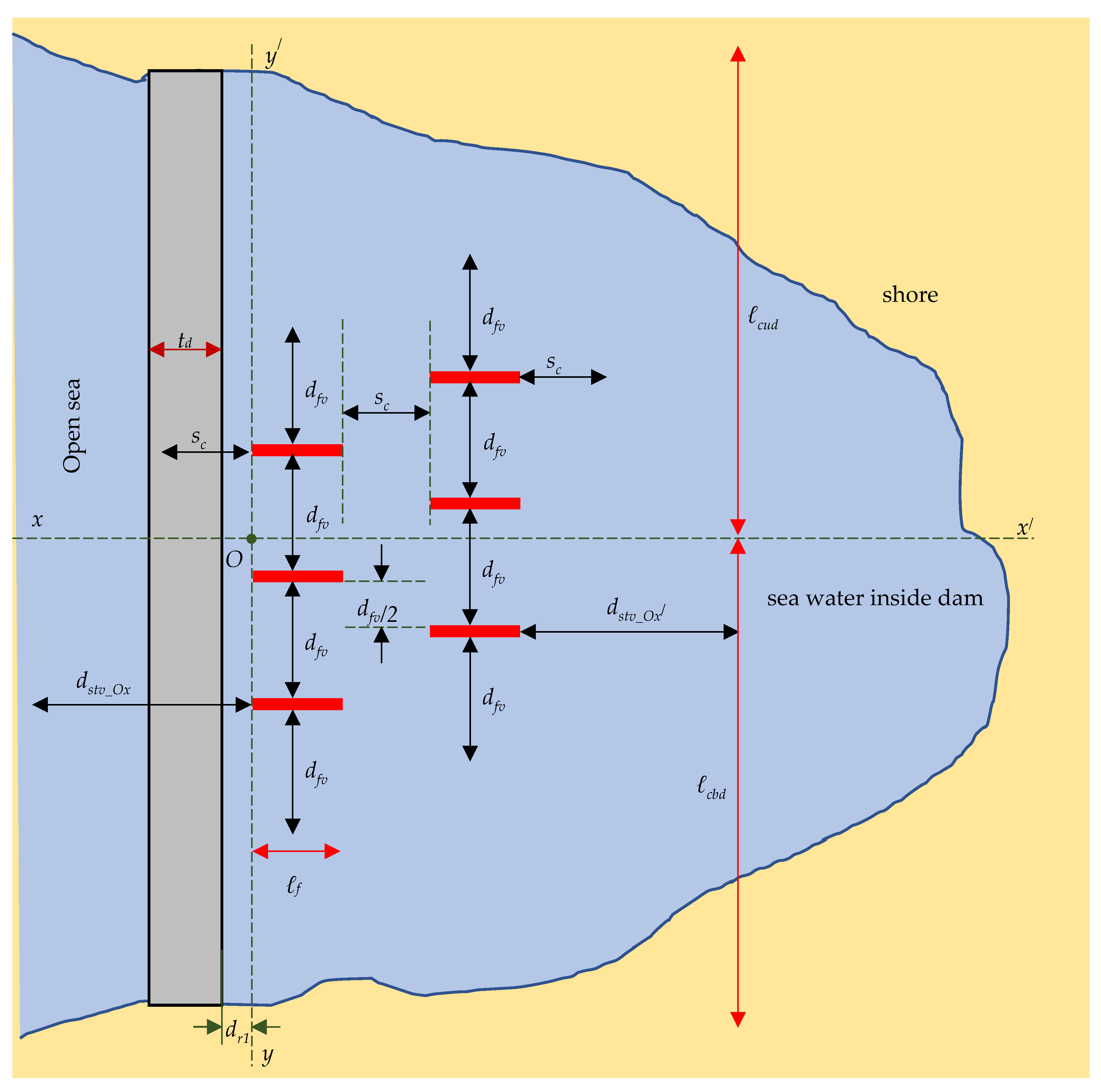
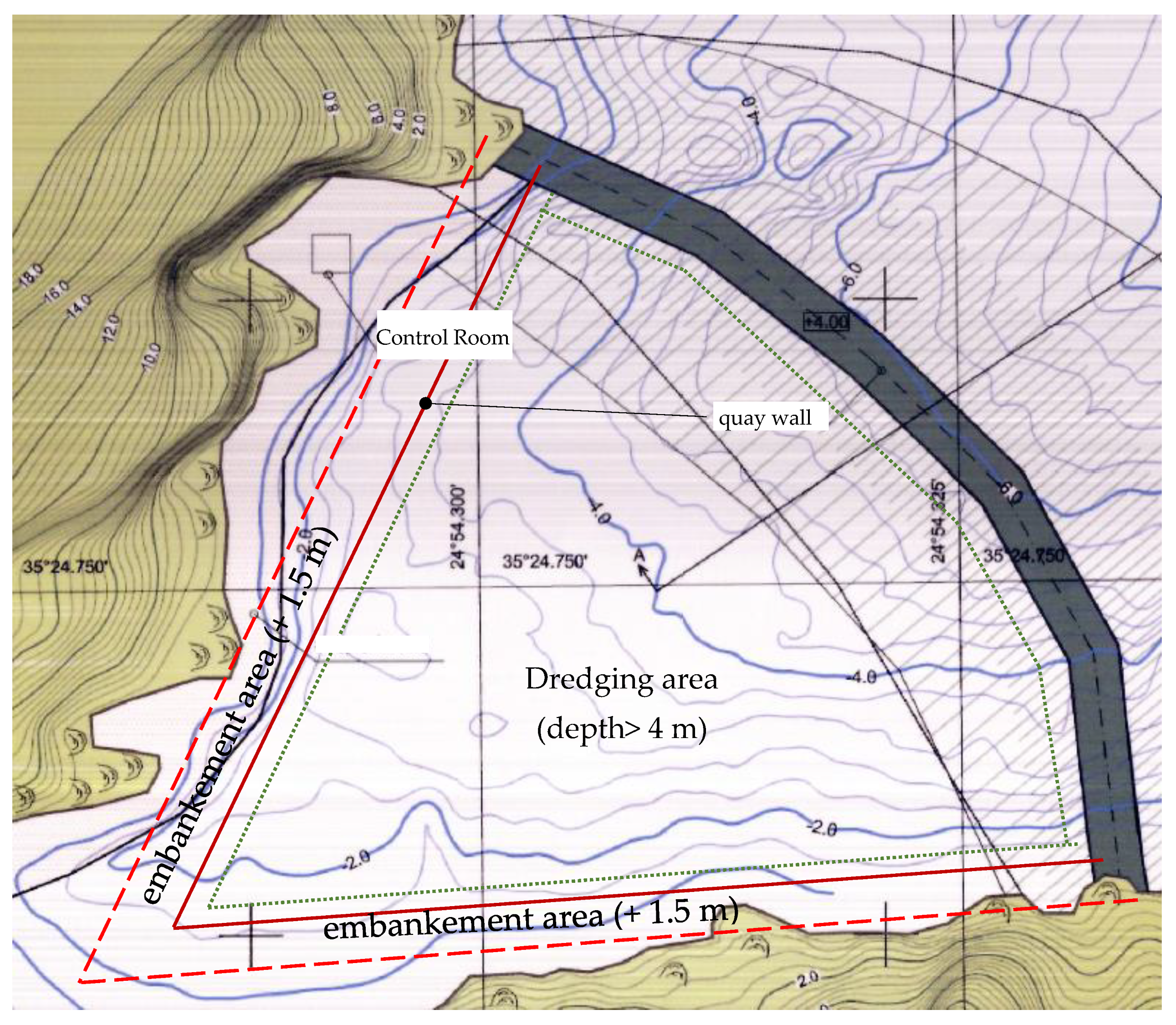
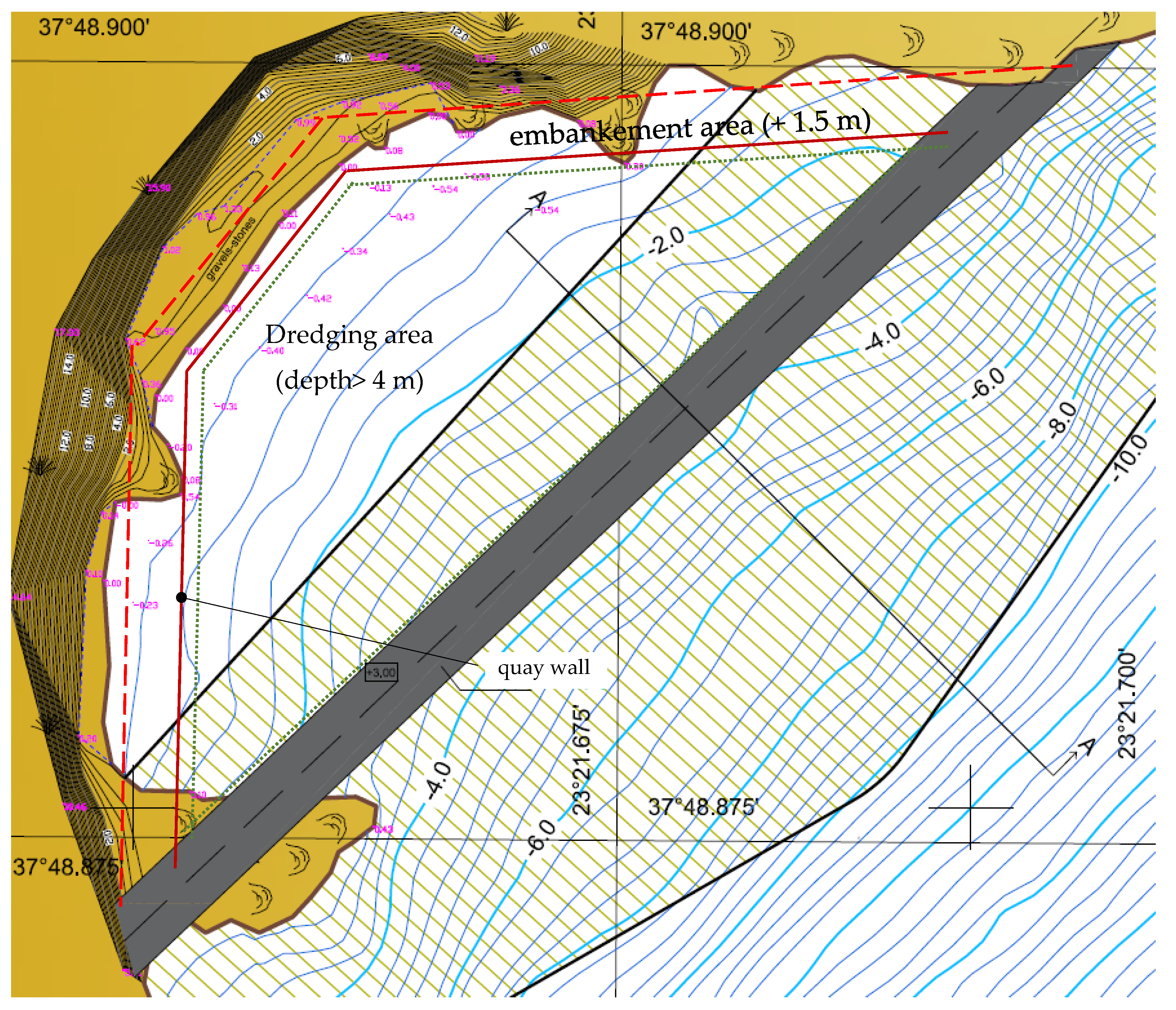
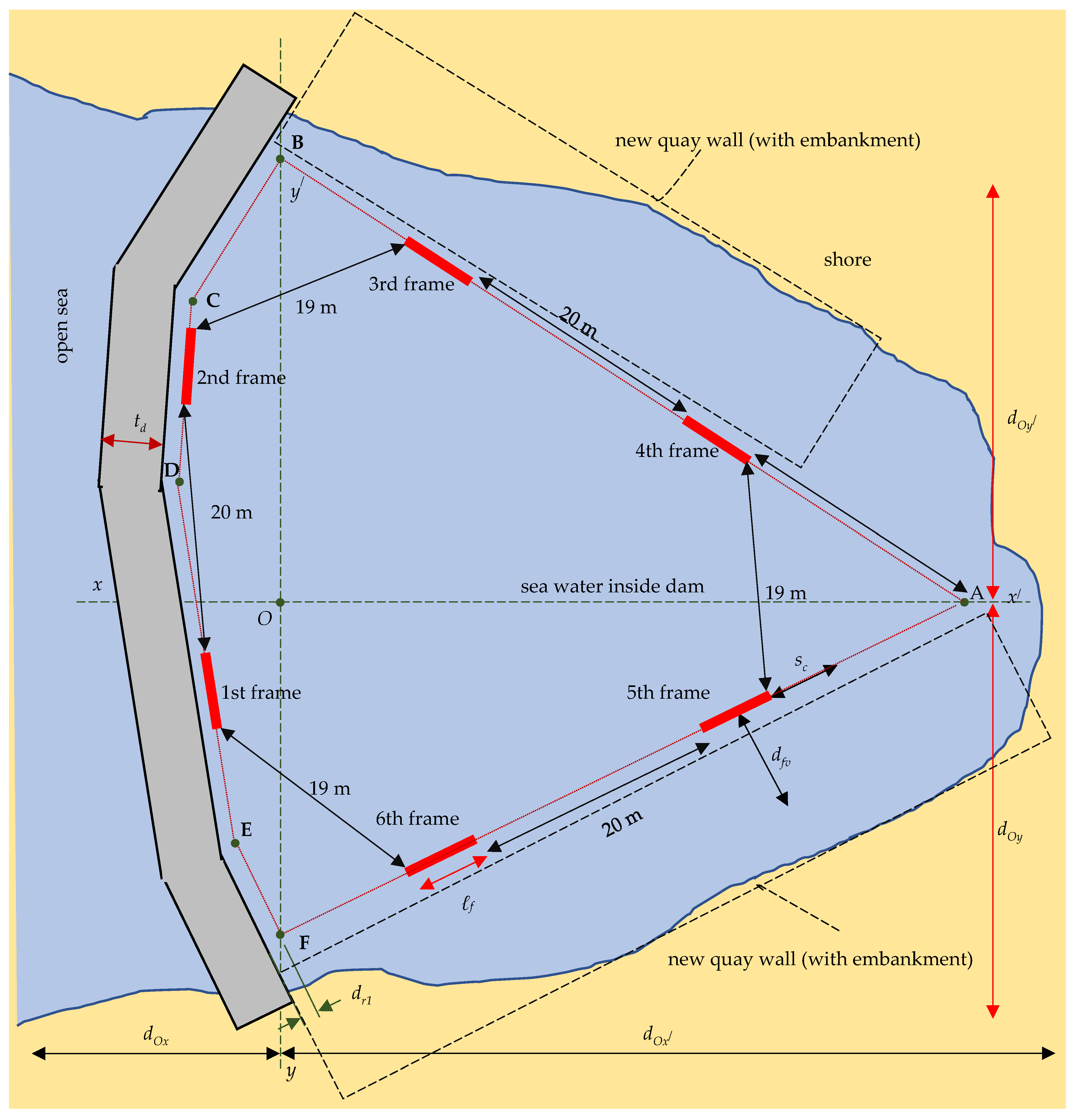
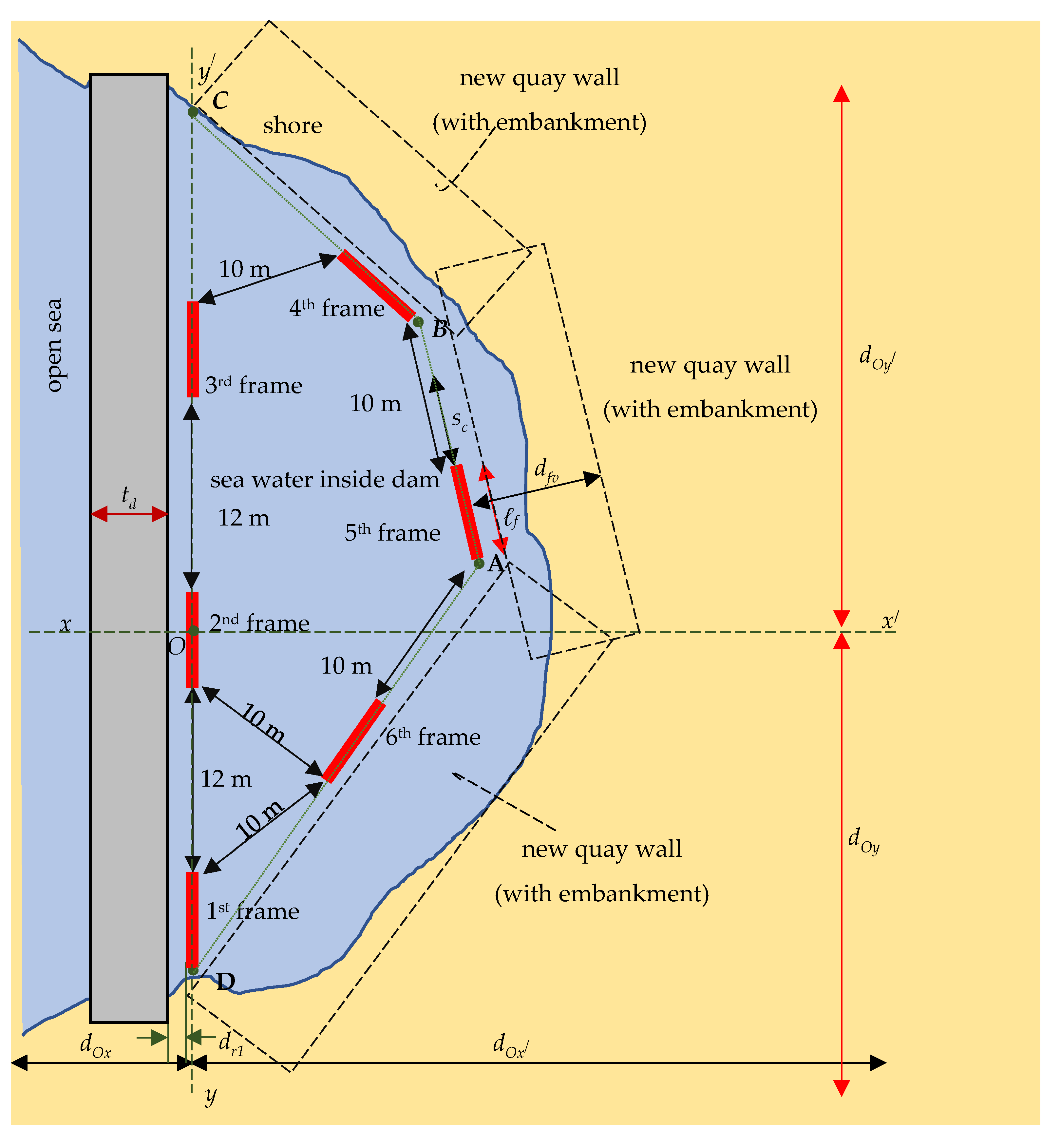
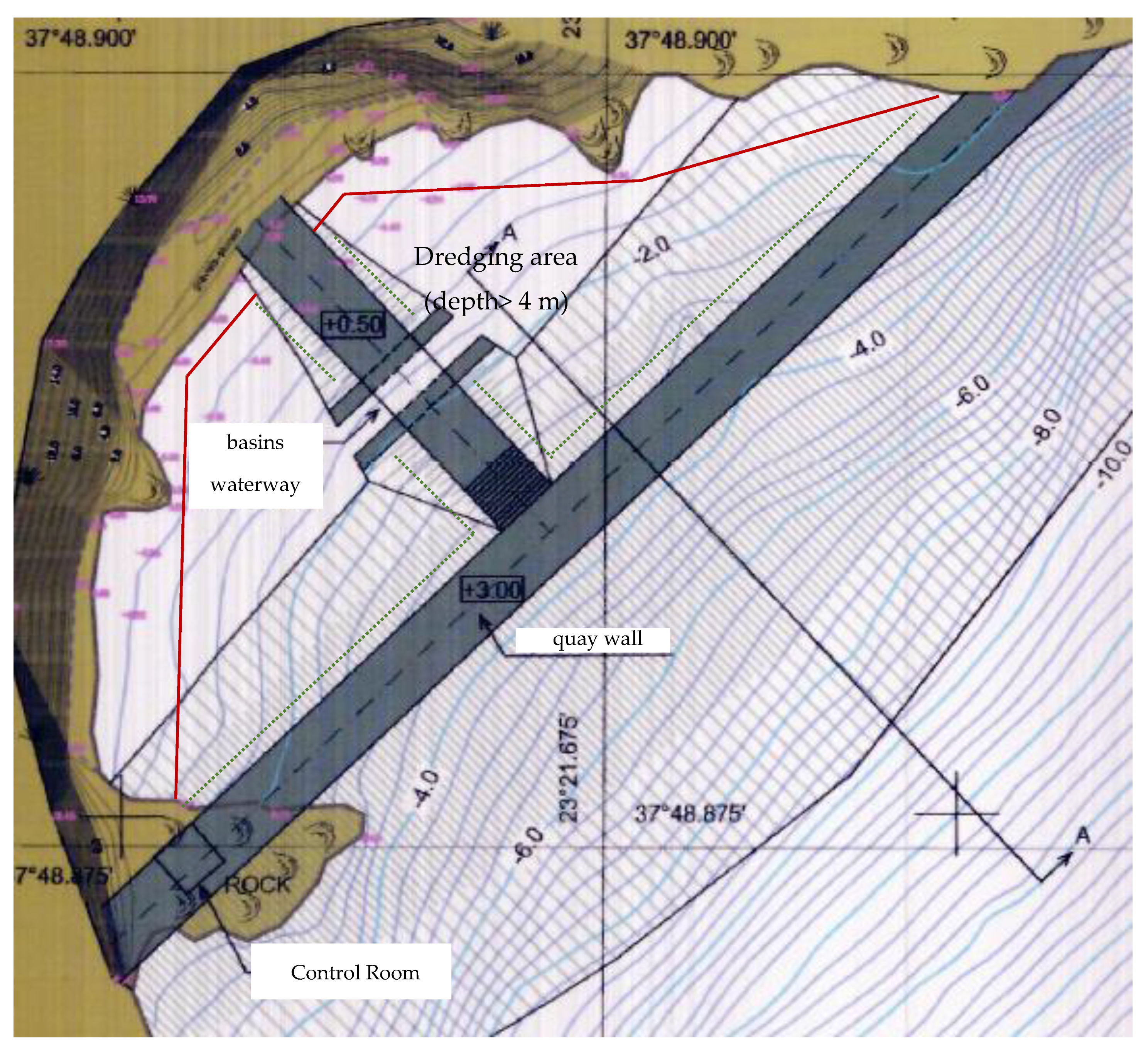
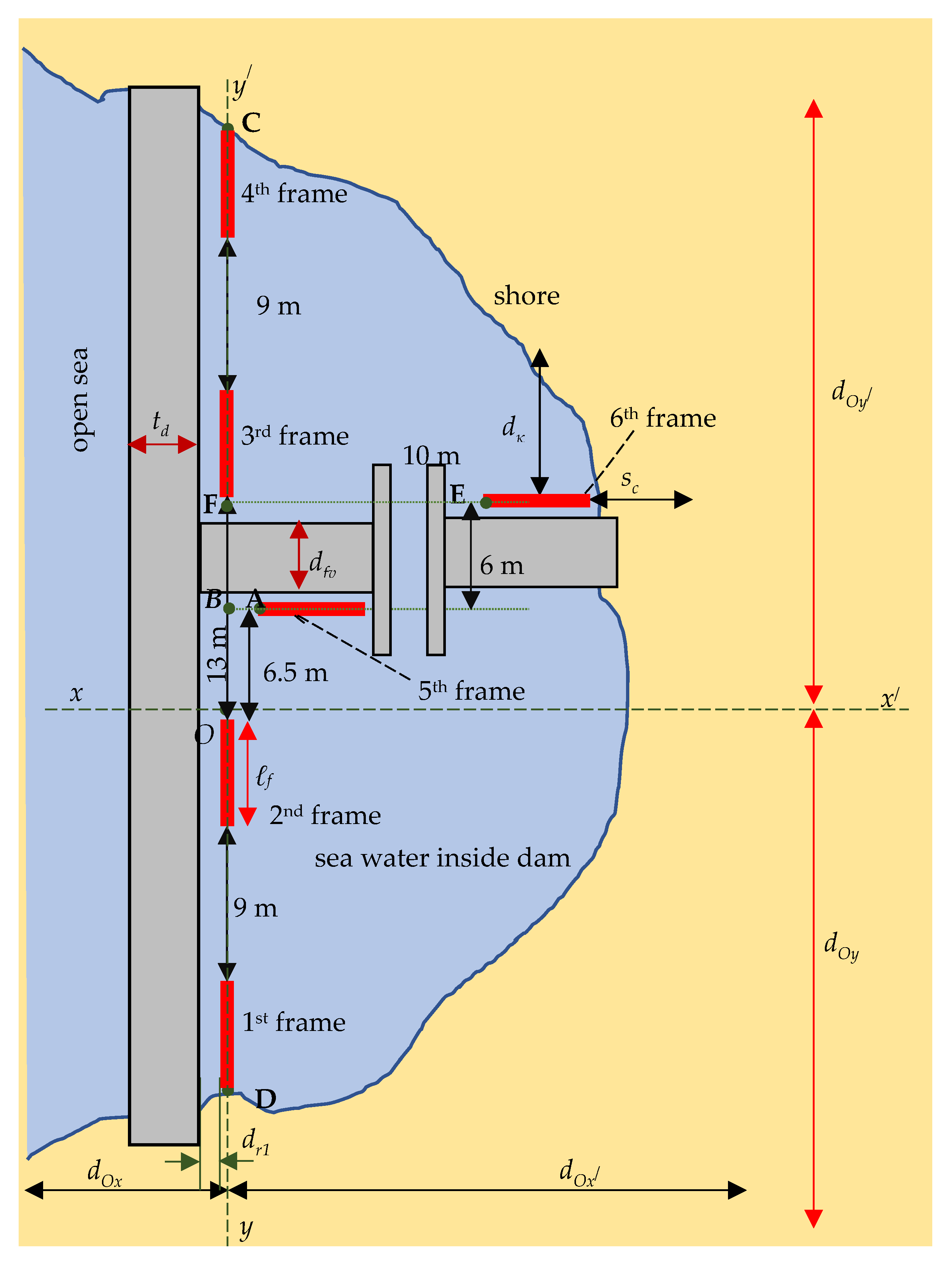
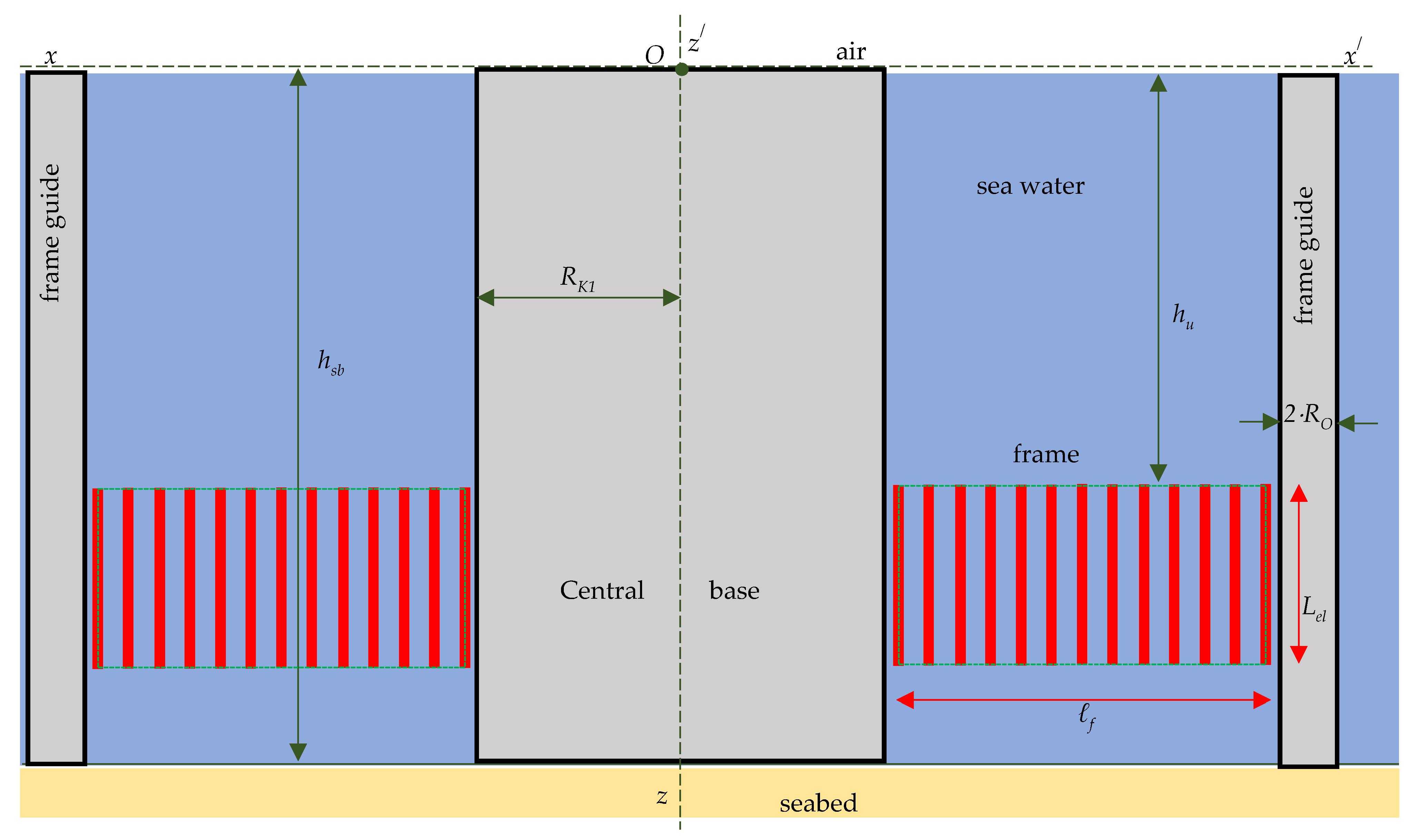

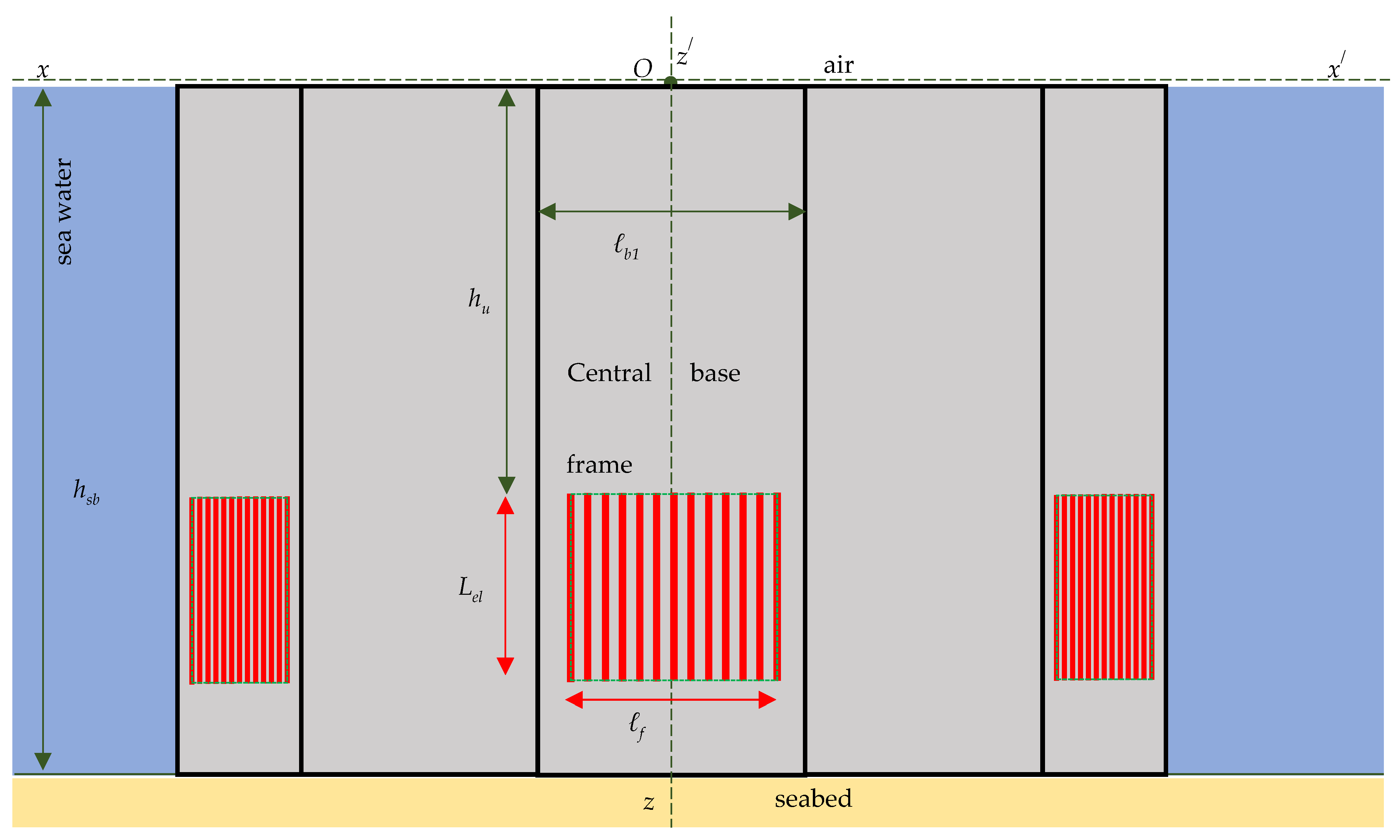

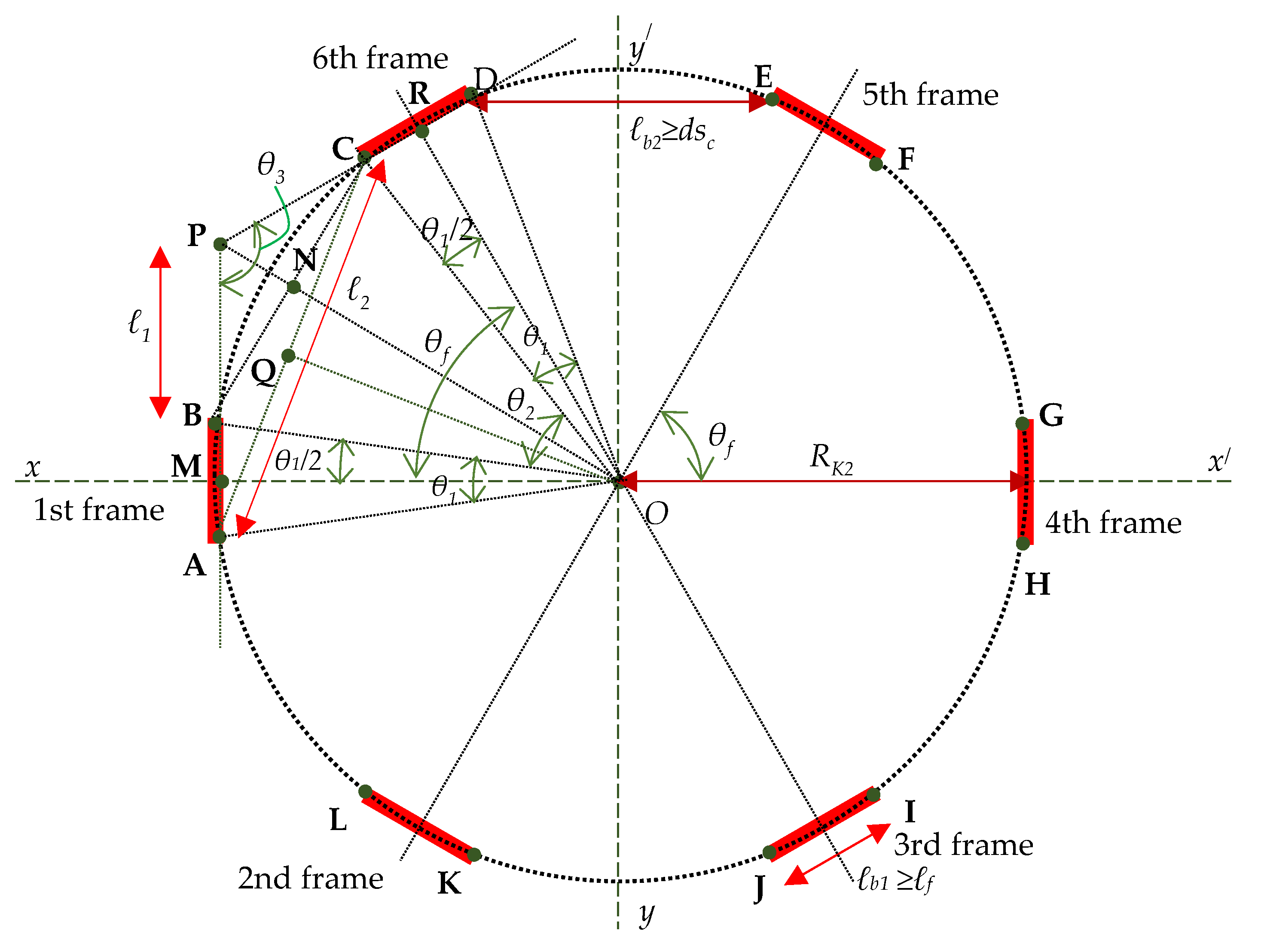
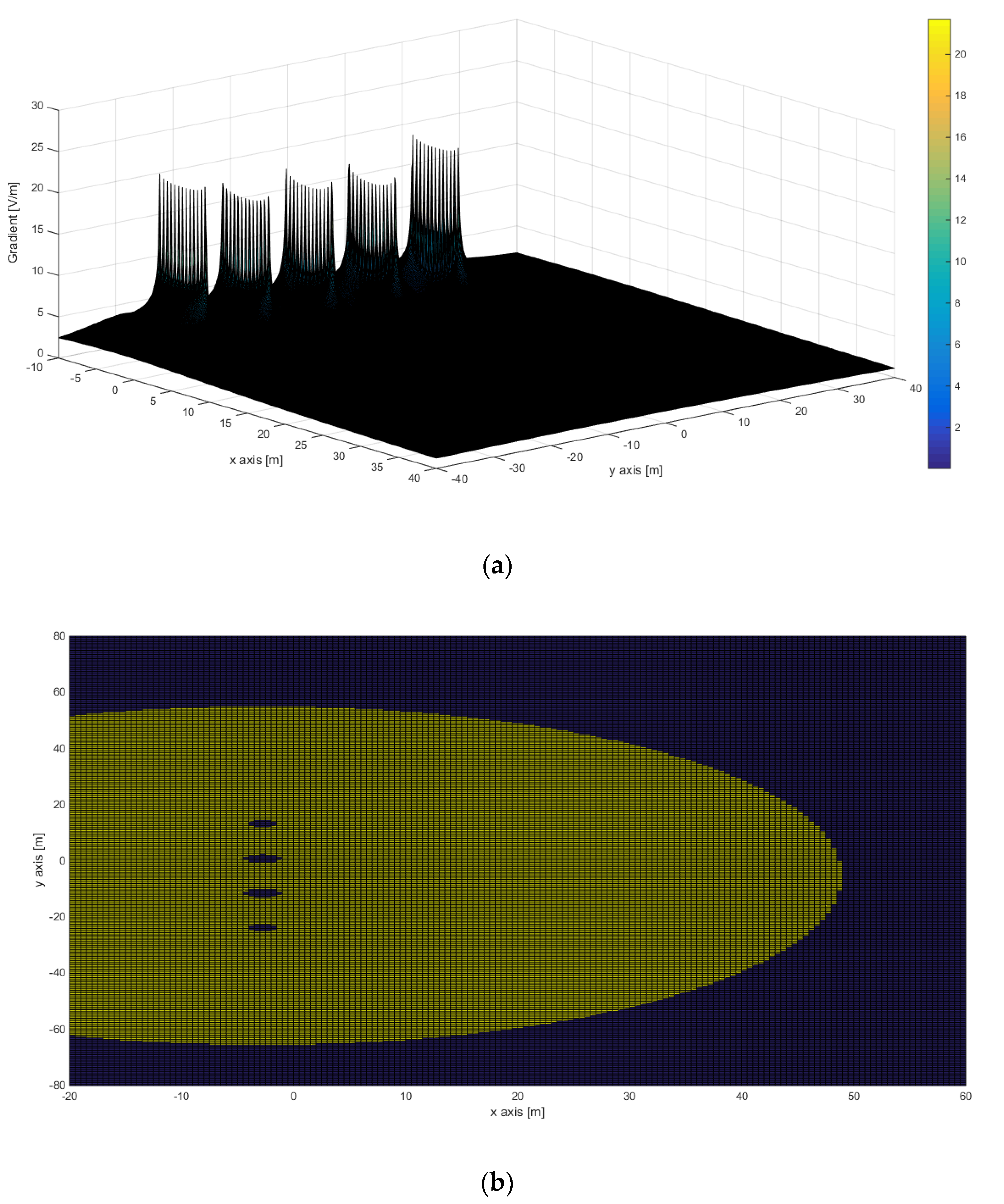

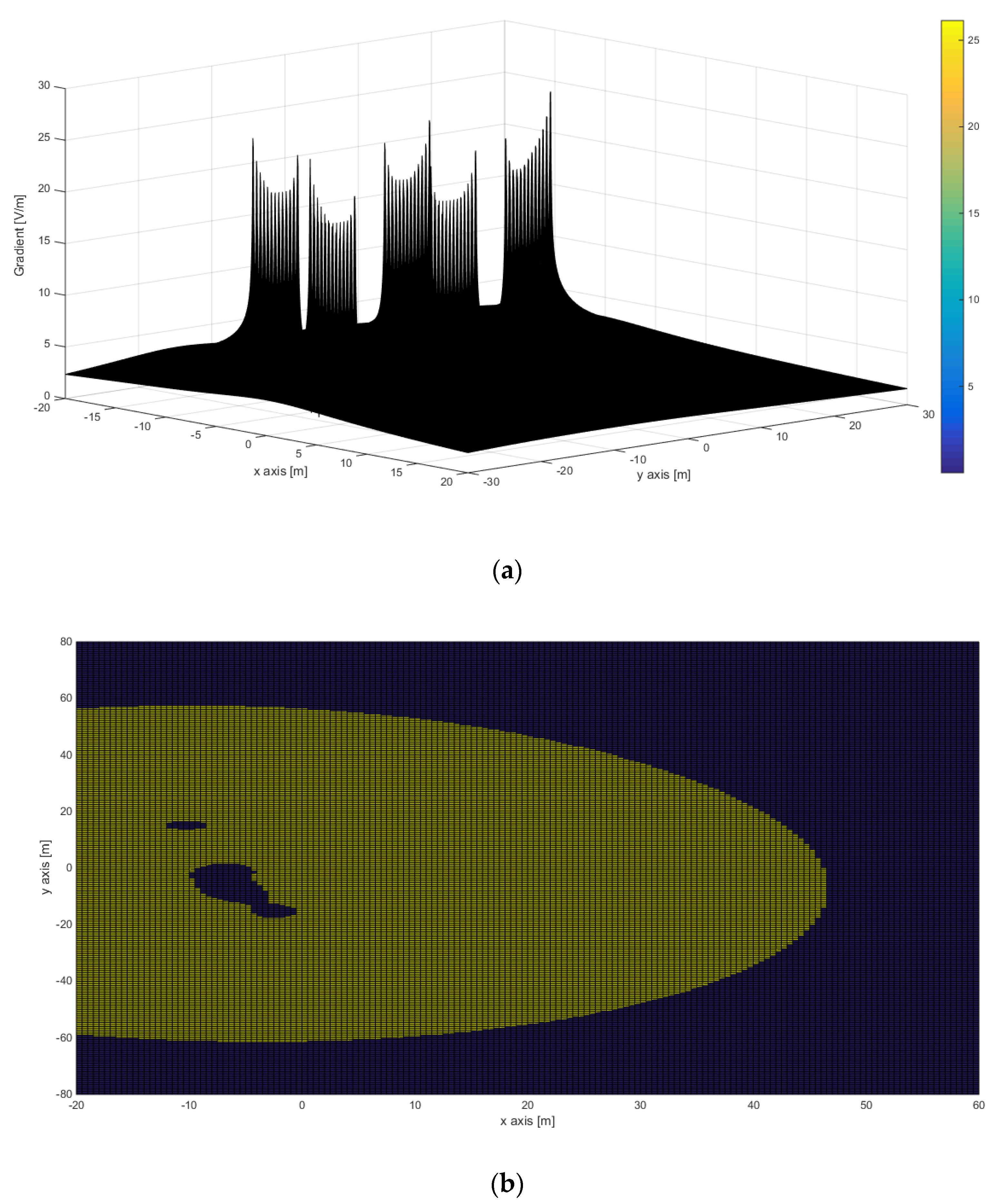

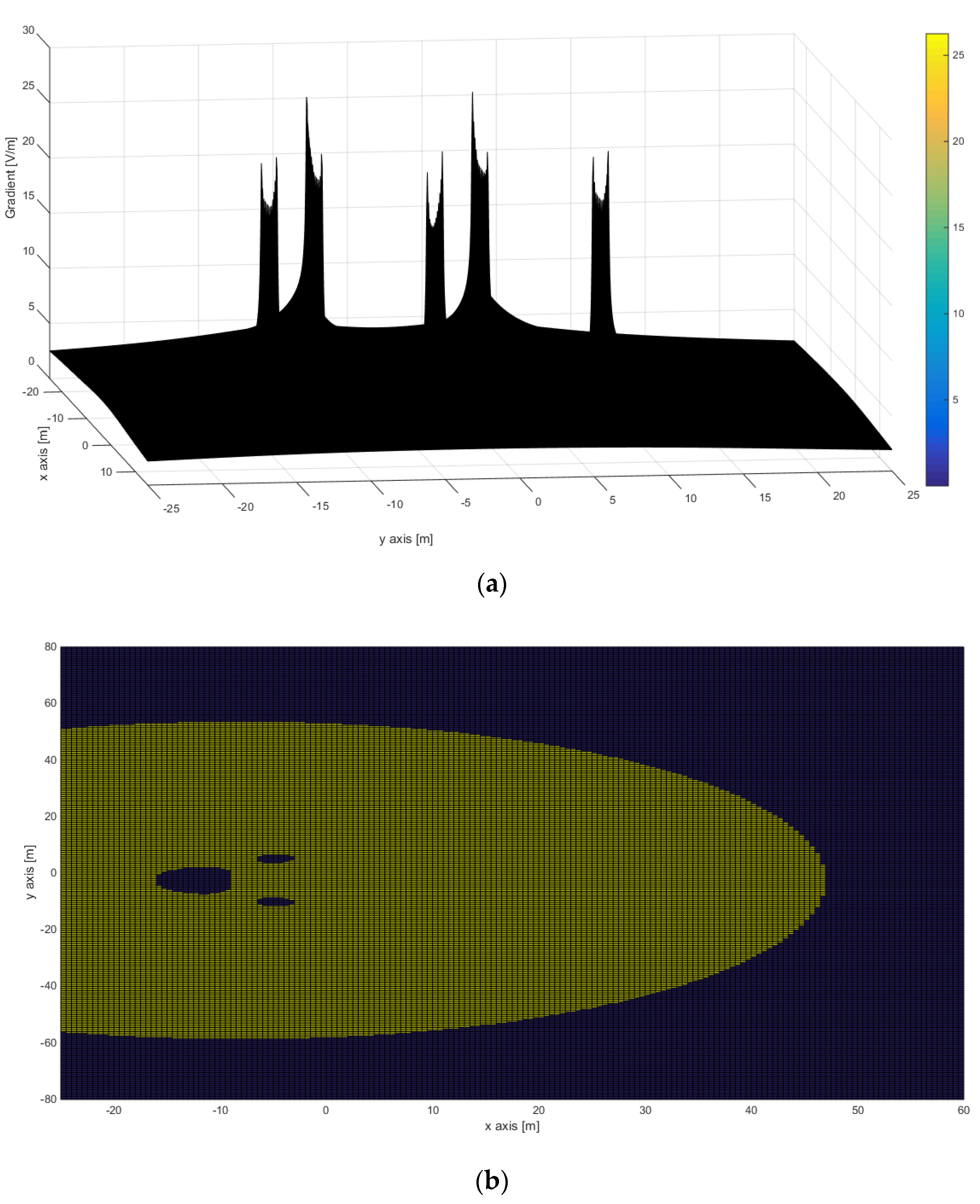
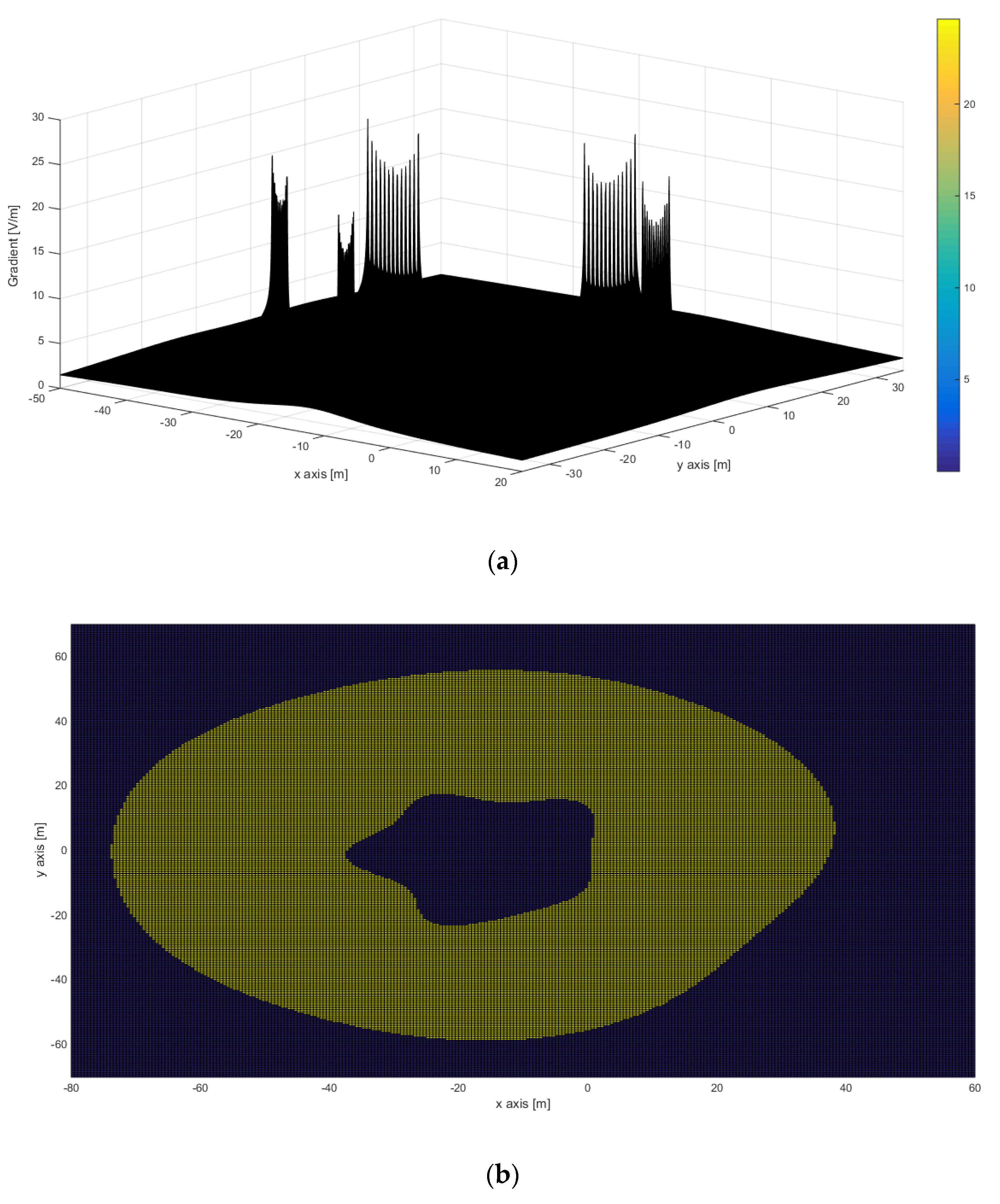
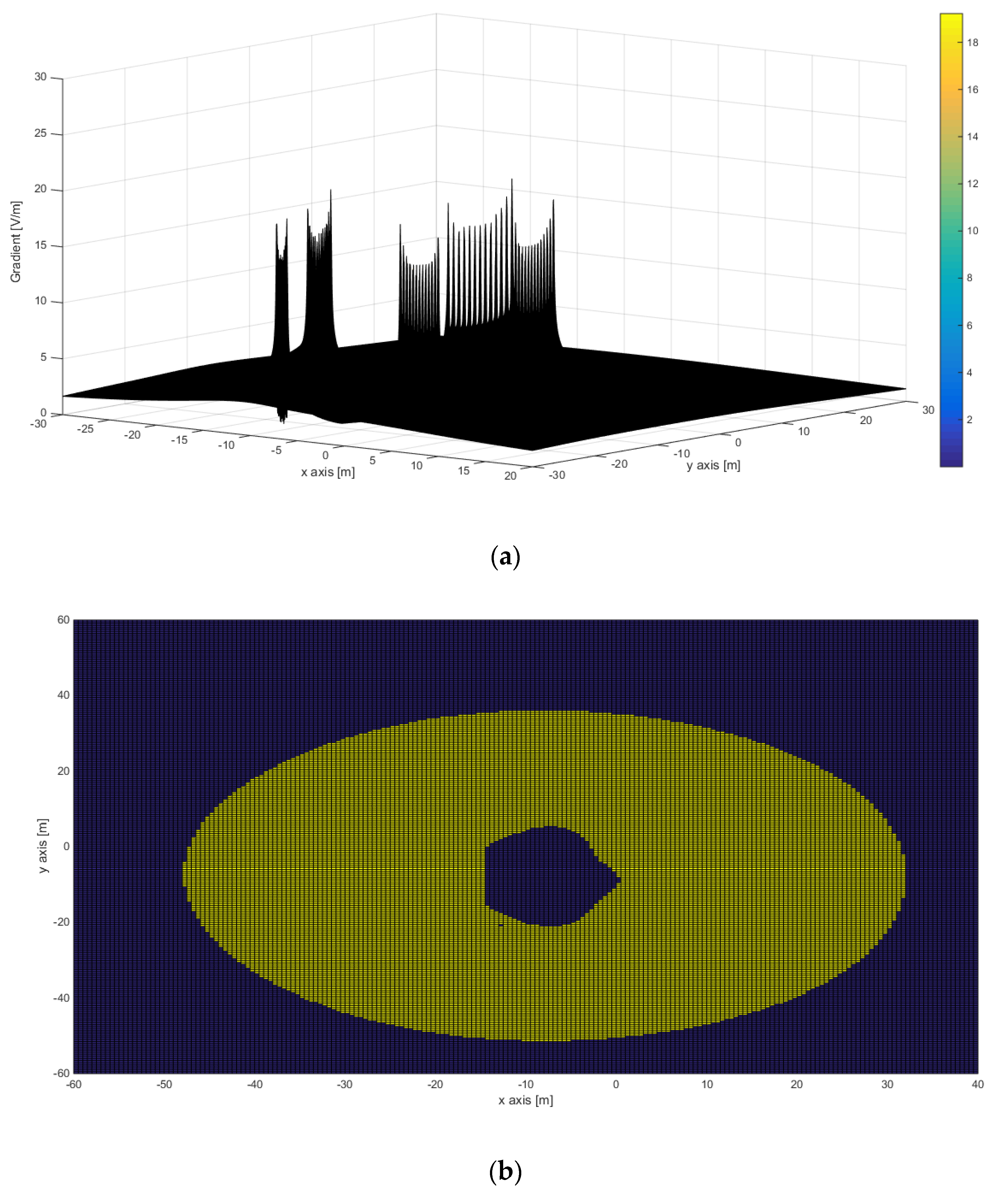
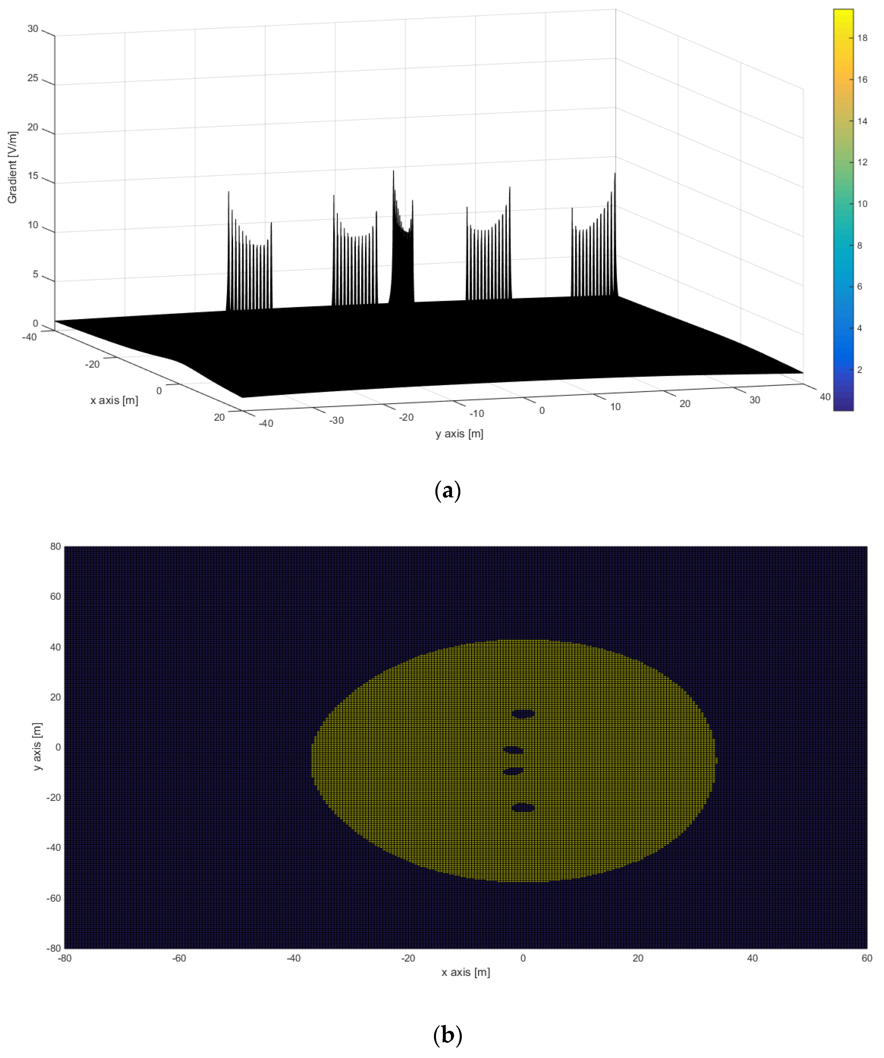
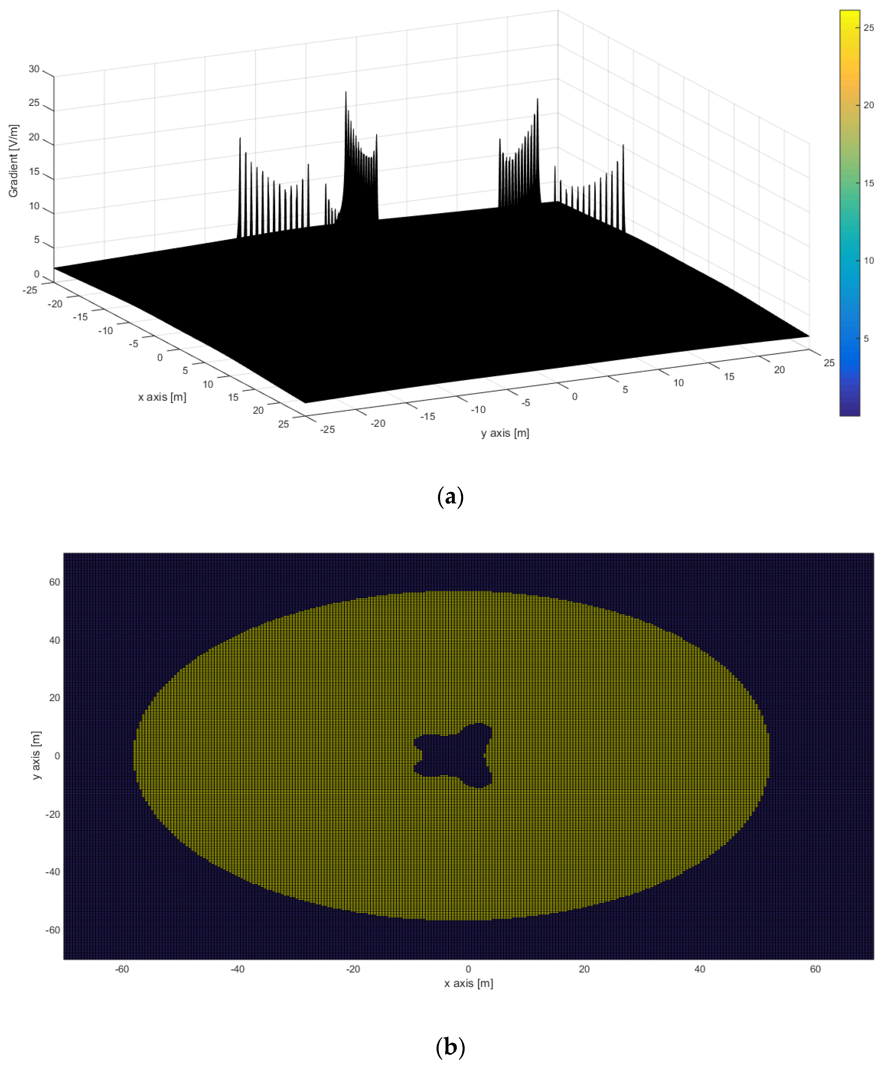
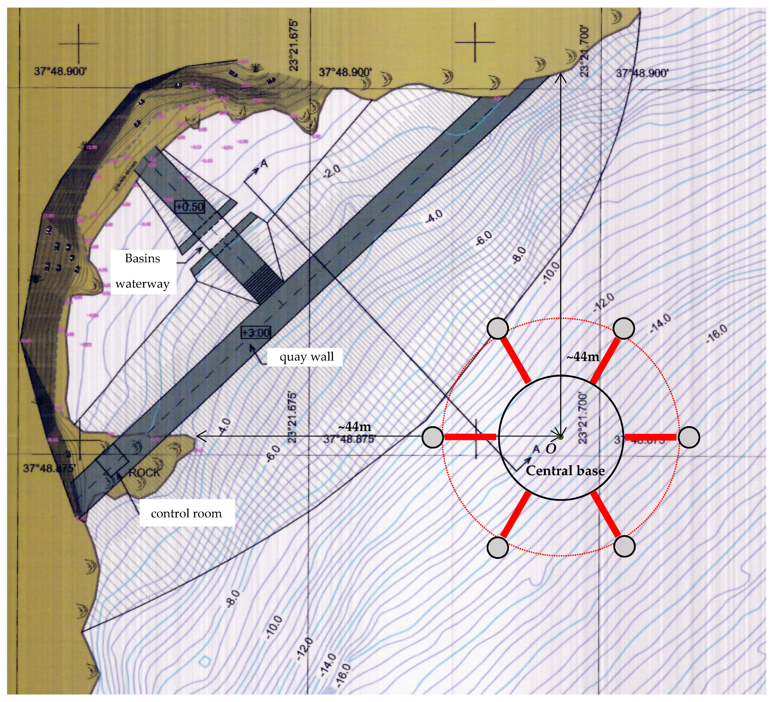
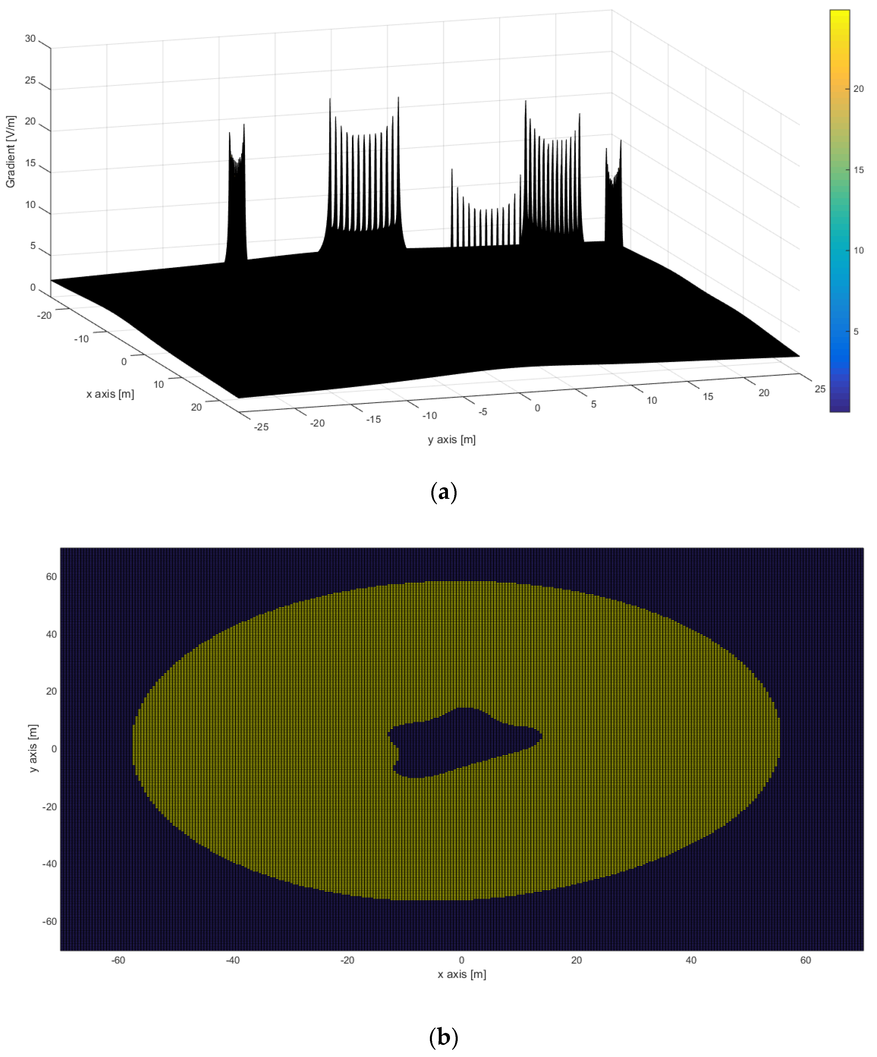
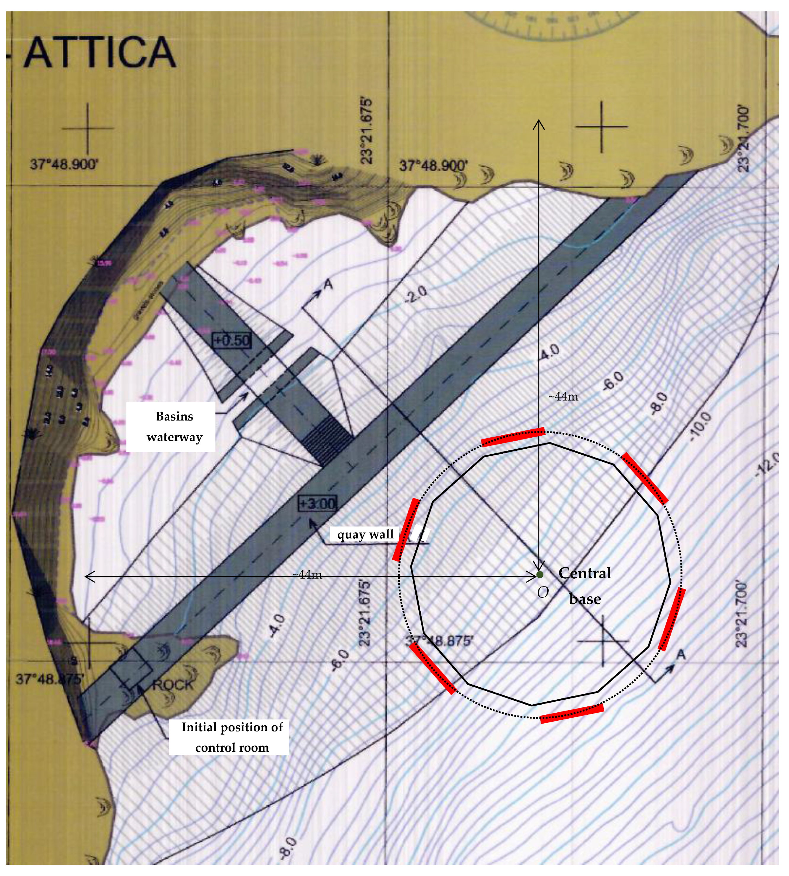

| Supply Method | Jst (A/m2) | dstv (m) | ℓcud (m) | ℓcbd (m) | ℓbc (m) | ℓuc (m) | sbc (m) | suc (m) | ypr (m) | Dypr (m) | Εmax (V/m) | Vrel_max (V) | Rel (Ω) | |
|---|---|---|---|---|---|---|---|---|---|---|---|---|---|---|
| Korakia, Crete | 6 frames operating | 18.33 | 46.60 | −62.11 | 62.11 | −27.55 | 27.55 | 34.56 | 34.56 | 38.45 | −23.66 | 20.76 | 19,562 | 16.84 |
| 5 frames operating (except for no. 6) | 22.00 | 48.70 | −65.75 | 54.73 | −27.55 | 16.53 | 38.20 | 38.19 | 27.43 | −27.29 *1 | 24.98 | 22,475 | 19.26 | |
| 5 frames operating (except for no. 5) | 22.00 | 46.82 | −64.91 | 17.05 | −27.55 | 5.51 | 37.36 | 11.54 | 16.41 | −0.64 *2 | 24.76 | 21,621 | 10.53 | |
| −38.45 | −26.46 | |||||||||||||
| 23.85 | 59.79 | 27.55 | 27.55 | 3.70 | 32.24 | 16.65 | 7.20 | |||||||
| 38.45 | −21.34 | |||||||||||||
| 5 frames operating (except for no. 4) | 22.00 | 45.16 | −63.80 | 3.50 | −27.55 | −5.51 | 36.25 | 9.01 | 5.39 | 1.89 | 24.61 | 20,378 | 17.46 | |
| −38.45 | −25.35 | |||||||||||||
| 9.80 | 62.22 | 16.53 | 27.55 | 6.73 | 34.67 | 5.63 | 4.17 | |||||||
| 38.45 | −23.77 | |||||||||||||
| Stachtoroi, Attica | 6 frames operating | 17.27 | 34.20 | −46.22 | 46.22 | −20.31 | 20.31 | 25.92 | 25.92 | 28.31 | −17.92 | 15.89 | 16,213 | 13.89 |
| 5 frames operating (except for no. 6) | 22.00 | 35.72 | −48.92 | 40.79 | −20.31 | 12.18 | 28.61 | 28.61 | 20.18 | −20.61 *3 | 19.08 | 18,397 | 15.76 | |
| 5 frames operating (except for no. 5) | 22.00 | 34.35 | −48.29 | 14.65 | −20.31 | 4.06 | 27.98 | 10.59 | 12.06 | −2.59 *4 | 18.90 | 17,624 | 15.10 | |
| −28.31 | −19.98 | |||||||||||||
| 15.69 | 44.39 | 20.31 | 20.31 | 4.61 | 24.08 | 12.31 | 3.39 | |||||||
| 28.31 | −16.08 | |||||||||||||
| 5 frames operating (except for no. 4) | 22.00 | 33.15 | −47.46 | 3.15 | −20.31 | −4.06 | 27.15 | 7.21 | 3.94 | 0.79 | 18.79 | 16,470 | 14.11 | |
| −28.31 | −19.15 | |||||||||||||
| 6.35 | 46.30 | 12.18 | 20.31 | 5.83 | 25.99 | 4.18 | 2.17 | |||||||
| 28.31 | −17.99 |
| Supply Method | Jst (A/m2) | dstv_Ox (m) | dstv_Ox/ (m) | ℓcud (m) | ℓcbd (m) | Εoff (V/m) | Εmax (V/m) | Vrel_max (V) | Rel (Ω) | |
|---|---|---|---|---|---|---|---|---|---|---|
| Korakia, Crete | 6 frames operating | 18.33 | 47.81 | 47.81 | −58.48 | 58.48 | − | 22.05 | 24,545 | 21.03 |
| 5 frames operating (except for no. 6 or no. 2) | 22.00 | 49.25 | 47.55 | −61.10 | 55.20 | 2.98 | 26.12 | 26,460 | 22.67 | |
| 5 frames operating (except for no. 5 or no. 1) | 22.00 | 47.55 | 49.25 | −61.10 | 55.20 | 2.98 | 26.12 | 26,978 | 23.12 | |
| 5 frames operating (except for no. 4) | 22.00 | 48.40 | 45.67 | −59.02 | 59.02 | 2.06 | 25.90 | 24,354 | 20.87 | |
| 5 frames operating (except for no. 3) | 22.00 | 45.67 | 48.40 | −59.02 | 59.02 | 2.06 | 25.90 | 23,752 | 20.35 | |
| Stachtoroi, Attica | 6 frames operating | 18.33 | 35.72 | 35.72 | −43.74 | 43.74 | − | 16.99 | 19,824 | 16.99 |
| 5 frames operating (except for no. 6 or no. 2) | 22.00 | 36.78 | 35.50 | −45.70 | 41.28 | 3.05 | 20.03 | 21,190 | 18.16 | |
| 5 frames operating (except for no. 5 or no. 1) | 22.00 | 35.50 | 36.78 | −45.70 | 41.28 | 3.05 | 20.03 | 21,476 | 18.40 | |
| 5 frames operating (except for no. 4) | 22.00 | 36.14 | 34.14 | −44.15 | 44.15 | 2.06 | 19.83 | 19,549 | 16.75 | |
| 5 frames operating (except for no. 3) | 22.00 | 34.14 | 36.14 | −44.15 | 44.15 | 2.06 | 19.83 | 18,684 | 16.01 |
| Supply Method | Jst (A/m2) | dstv_Ox (m) | dstv_Ox/ (m) | ℓcud (m) | ℓcbd (m) | Εoff (V/m) | Εmax (V/m) | Vrel_max (V) | Rel (Ω) | |
|---|---|---|---|---|---|---|---|---|---|---|
| Korakia, Crete | 6 frames operating | 18.33 | 47.02 | 47.02 | −59.28 | 59.28 | − | 22.09 | 23,378 | 20.03 |
| 5 frames operating (except for no. 6) | 22.00 | 49.01 | 47.40 | −62.41 | 54.10 | 3.09 | 26.13 | 26,142 | 22.40 | |
| 5 frames operating (except for no. 5) | 22.00 | 46.40 | 48.06 | −61.67 | 57.25 | 2.57 | 26.14 | 25,914 | 22.20 | |
| 5 frames operating (except for no. 4) | 22.00 | 47.60 | 44.72 | −60.64 | 59.11 | 1.82 | 26.08 | 23,915 | 20.49 | |
| 5 frames operating (except for no. 3) | 22.00 | 44.72 | 47.60 | −59.11 | 60.64 | 1.82 | 26.08 | 24,374 | 20.88 | |
| 5 frames operating (except for no. 2) | 22.00 | 48.06 | 46.40 | −57.25 | 61.67 | 2.57 | 26.14 | 24,775 | 21.23 | |
| 5 frames operating (except for no. 1) | 22.00 | 47.40 | 49.01 | −54.10 | 62.41 | 3.09 | 26.13 | 25,817 | 22.12 | |
| Stachtoroi, Attica | 6 frames operating | 18.33 | 35.53 | 35.53 | −44.01 | 44.01 | − | 17.03 | 19,537 | 16.74 |
| 5 frames operating (except for no. 6) | 22.00 | 36.95 | 35.69 | −46.27 | 40.27 | 3.35 | 20.14 | 21,581 | 18.49 | |
| 5 frames operating (except for no. 5) | 22.00 | 34.95 | 36.26 | −45.62 | 42.67 | 2.83 | 20.05 | 21,055 | 18.04 | |
| 5 frames operating (except for no. 4) | 22.00 | 36.00 | 33.97 | −44.94 | 43.93 | 2.15 | 20.00 | 19,778 | 16.95 | |
| 5 frames operating (except for no. 3) | 22.00 | 33.97 | 36.00 | −43.93 | 44.94 | 2.15 | 20.00 | 19,569 | 16.77 | |
| 5 frames operating (except for no. 2) | 22.00 | 36.26 | 34.95 | −42.67 | 45.62 | 2.83 | 20.05 | 20,218 | 17.32 | |
| 5 frames operating (except for no. 1) | 22.00 | 35.69 | 36.95 | −40.27 | 46.27 | 3.35 | 20.14 | 21,212 | 18.17 |
| Supply Method | Jst (A/m2) | dstv_Ox (m) | dstv_Ox/ (m) | ℓcud (m) | ℓcbd (m) | Εoff (V/m) | Εmax (V/m) | Vrel_max (V) | Rel (Ω) | |
|---|---|---|---|---|---|---|---|---|---|---|
| Korakia, Crete | 6 frames operating | 18.33 | 45.07 | 45.07 | −56.38 | 56.38 | − | 22.14 | 24,086 | 20.64 |
| 5 frames operating (except for no. 6 or no. 2) | 22.00 | 46.64 | 44.05 | −58.35 | 54.18 | 3.31 | 26.29 | 25,705 | 22.02 | |
| 5 frames operating (except for no. 5 or no. 1) | 22.00 | 44.05 | 46.64 | −58.35 | 54.18 | 3.31 | 26.29 | 24,844 | 21.29 | |
| 5 frames operating (except for no. 4) | 22.00 | 46.31 | 43.08 | −56.69 | 56.69 | 2.50 | 25.78 | 25,094 | 21.50 | |
| 5 frames operating (except for no. 3) | 22.00 | 43.08 | 46.31 | −56.69 | 56.69 | 2.50 | 25.79 | 21,572 | 18.48 | |
| Stachtoroi, Attica | 6 frames operating | 18.33 | 32.68 | 32.68 | −41.89 | 41.89 | − | 17.09 | 19,140 | 16.40 |
| 5 frames operating (except for no. 6 or no. 2) | 22.00 | 33.91 | 31.84 | −43.35 | 40.31 | 3.25 | 20.16 | 20,346 | 17.43 | |
| 5 frames operating (except for no. 5 or no. 1) | 22.00 | 31.84 | 33.91 | −43.35 | 40.31 | 3.25 | 20.16 | 19,402 | 16.62 | |
| 5 frames operating (except for no. 4) | 22.00 | 33.69 | 31.13 | −42.12 | 42.12 | 2.54 | 19.80 | 19,975 | 17.12 | |
| 5 frames operating (except for no. 3) | 22.00 | 31.13 | 33.69 | −42.12 | 42.12 | 2.54 | 19.80 | 16,908 | 14.49 |
| Supply Method | Jst (A/m2) | dstv_Ox (m) | dstv_Ox/ (m) | ℓcud (m) | ℓcbd (m) | Εoff (V/m) | Εmax (V/m) | Vrel_max (V) | Rel (Ω) | |
|---|---|---|---|---|---|---|---|---|---|---|
| Korakia, Crete | 6 frames operating | 18.33 | 44.96 | 44.96 | −56.55 | 56.55 | - | 22.08 | 23,861 | 20.44 |
| 5 frames operating (except for no. 6) | 22.00 | 46.74 | 44.18 | −58.89 | 53.35 | 3.42 | 26.25 | 25,942 | 22.23 | |
| 5 frames operating (except for no. 5) | 22.00 | 43.66 | 46.38 | −58.15 | 55.28 | 3.12 | 26.21 | 24,562 | 21.05 | |
| 5 frames operating (except for no. 4) | 22.00 | 46.22 | 42.96 | −57.41 | 56.29 | 2.47 | 25.79 | 25,004 | 21.42 | |
| 5 frames operating (except for no. 3) | 22.00 | 42.96 | 46.22 | −56.29 | 57.41 | 2.47 | 25.79 | 22,275 | 19.09 | |
| 5 frames operating (except for no. 2) | 22.00 | 46.38 | 43.66 | −55.28 | 58.15 | 3.12 | 26.21 | 25,021 | 21.44 | |
| 5 frames operating (except for no. 1) | 22.00 | 44.18 | 46.74 | −53.35 | 58.89 | 3.42 | 26.25 | 24,625 | 21.10 | |
| Stachtoroi, Attica | 6 frames operating | 18.33 | 32.60 | 32.60 | −42.01 | 42.01 | - | 17.04 | 18,993 | 16.27 |
| 5 frames operating (except for no. 6) | 22.00 | 33.98 | 31.93 | −43.74 | 39.70 | 3.37 | 20.12 | 20,506 | 17.57 | |
| 5 frames operating (except for no. 5) | 22.00 | 31.57 | 33.70 | −43.18 | 41.11 | 3.07 | 20.09 | 19,192 | 16.44 | |
| 5 frames operating (except for no. 4) | 22.00 | 33.62 | 31.04 | −42.65 | 41.82 | 2.51 | 19.80 | 19,906 | 17.06 | |
| 5 frames operating (except for no. 3) | 22.00 | 31.04 | 33.62 | −41.82 | 42.65 | 2.51 | 19.80 | 17,371 | 14.88 | |
| 5 frames operating (except for no. 2) | 22.00 | 33.70 | 31.57 | −41.11 | 43.18 | 3.07 | 20.09 | 19,915 | 17.06 | |
| 5 frames operating (except for no. 1) | 22.00 | 31.93 | 33.98 | −39.70 | 43.74 | 3.37 | 20.12 | 19,279 | 16.52 |
| Supply Method | Jst (A/m2) | dOx (m) | dOx/ (m) | dOy (m) | dOy/ (m) | Εoff (V/m) | Εmax (V/m) | Vrel_max (V) | Rel (Ω) | |
|---|---|---|---|---|---|---|---|---|---|---|
| Korakia, Crete | 6 frames operating | 18.33 | 41.15 | −70.64 | 52.67 | −59.71 | - | 20.69 | 19,249 | 16.49 |
| 5 frames operating (except for no. 6) | 22.00 | 43.22 | −72.50 | 42.01 | −62.92 | 1.49 | 24.39 | 21,873 | 18.74 | |
| 5 frames operating (except for no. 5) | 22.00 | 44.60 | −66.70 | 52.90 | −62.71 | 1.53 | 24.31 | 21,792 | 18.67 | |
| 5 frames operating (except for no. 4) | 22.00 | 44.25 | −66.94 | 55.09 | −60.53 | 1.45 | 24.78 | 21,229 | 18.19 | |
| 5 frames operating (except for no. 3) | 22.00 | 42.58 | −72.74 | 55.80 | −50.24 | 1.45 | 24.72 | 19,927 | 17.07 | |
| 5 frames operating (except for no. 2) | 22.00 | 38.05 | −74.04 | 55.67 | −58.98 | 1.55 | 24.62 | 18,879 | 16.18 | |
| 5 frames operating (except for no. 1) | 22.00 | 38.47 | −73.63 | 52.63 | −62.03 | 1.42 | 24.84 | 21,709 | 18.60 | |
| Stachtoroi, Attica | 6 frames operating | 18.33 | 30.55 | −45.70 | 42.32 | −48.73 | - | 16.42 | 16,022 | 13.73 |
| 5 frames operating (except for no. 6) | 22.00 | 31.00 | −45.59 | 41.28 | −50.65 | 1.61 | 19.21 | 16,730 | 14.33 | |
| 5 frames operating (except for no. 5) | 22.00 | 31.96 | −40.23 | 43.88 | −49.23 | 1.77 | 19.44 | 16,836 | 14.43 | |
| 5 frames operating (except for no. 4) | 22.00 | 32.55 | −46.26 | 44.94 | −43.82 | 2.07 | 19.49 | 17,804 | 15.25 | |
| 5 frames operating (except for no. 3) | 22.00 | 30.69 | −47.04 | 44.54 | −46.78 | 1.82 | 19.44 | 17,804 | 15.25 | |
| 5 frames operating (except for no. 2) | 22.00 | 27.14 | −46.59 | 42.37 | −50.02 | 1.45 | 19.21 | 16,653 | 14.27 | |
| 5 frames operating (except for no. 1) | 22.00 | 31.81 | −48.12 | 35.83 | −51.61 | 2.26 | 19.22 | 17,842 | 15.29 |
| Supply Method | Jst (A/m2) | dOx (m) | dOx/ (m) | dOy (m) | dOy/ (m) | Εoff (V/m) | Εmax (V/m) | Vrel_max (V) | Rel (Ω) |
|---|---|---|---|---|---|---|---|---|---|
| 6 frames operating | 18.33 | 31.80 | −43.95 | 40.97 | −52.90 | - | 16.49 | 15,696 | 13.45 |
| 5 frames operating (except for no. 6) | 22.00 | 33.51 | −37.45 | 42.85 | −53.85 | 2.28 | 19.40 | 16,292 | 13.96 |
| 5 frames operating (except for no. 5) | 22.00 | 30.66 | −43.21 | 41.71 | −53.79 | 0.81 | 19.32 | 15,604 | 13.37 |
| 5 frames operating (except for no. 4) | 22.00 | 33.74 | −45.84 | 43.75 | −44.94 | 1.94 | 19.60 | 17,705 | 15.17 |
| 5 frames operating (except for no. 3) | 22.00 | 30.36 | −44.51 | 42.68 | −52.17 | 2.10 | 19.35 | 16,875 | 14.46 |
| 5 frames operating (except for no. 2) | 22.00 | 30.85 | −44.99 | 40.05 | −54.78 | 2.05 | 19.47 | 17,491 | 14.99 |
| 5 frames operating (except for no. 1) | 22.00 | 34.07 | −46.48 | 32.08 | −55.85 | 1.99 | 19.69 | 18,312 | 15.69 |
| Supply Method | Jst (A/m2) | dOx (m) | dOx/ (m) | dOy (m) | dOy/ (m) | Εoff (V/m) | Εmax (V/m) | Vrel_max (V) | Rel (Ω) | VO (V) | ||
|---|---|---|---|---|---|---|---|---|---|---|---|---|
| Korakia, Crete | RK1 = 11 m, R1 = 0 m | 6 frames operating | 18.33 | 56.08 | −56.08 | 56.08 | −56.08 | - | 22.15 | (−)1323 | 1.133 | −978 |
| 5 frames operating (except for no. 6) | 22.00 | 55.44 | −57.69 | 58.09 | −53.37 | 2.59 | 26.11 | 7429 | 6.365 | −624 | ||
| 5 frames operating (except for no. 5) | 22.00 | 57.69 | −55.44 | 58.09 | −53.37 | 2.59 | 26.11 | (−)7193 | 6.163 | −3490 | ||
| 5 frames operating (except for no. 4) | 22.00 | 58.26 | −51.93 | 56.81 | −56.81 | 2.54 | 26.13 | (−)10,823 | 9.273 | −4267 | ||
| 5 frames operating (except for no. 3) | 22.00 | 57.69 | −55.44 | 53.37 | −58.09 | 2.59 | 26.11 | (−)7193 | 6.163 | −3490 | ||
| 5 frames operating (except for no. 2) | 22.00 | 55.44 | −57.69 | 53.37 | −58.09 | 2.56 | 26.11 | 7429 | 6.365 | −624 | ||
| 5 frames operating (except for no. 1) | 22.00 | 51.93 | −58.26 | 56.81 | −56.81 | 2.54 | 26.13 | 11,096 | 9.507 | 6624 | ||
| RK1 = 11 m, R1 = 0 m | 5 frames operating (except for no. 6) | 22.00 | 55.47 | −57.81 | 58.20 | −53.19 | 2.41 | 25.98 | 7844 | 6.721 | −833 | |
| 5 frames operating (except for no. 1) | 22.00 | 51.47 | −58.39 | 56.90 | −56.90 | 2.37 | 25.99 | 11,542 | 9.889 | 6832 | ||
| RK1 = 26 m, R1 = 0 m | 5 frames operating (except for no. 6) | 22.00 | 57.75 | −60.15 | 58.66 | −53.05 | 1.23 | 25.05 | 11,664 | 9.994 | −3298 | |
| 5 frames operating (except for no. 1) | 22.00 | 52.15 | −60.58 | 57.56 | −57.56 | 1.22 | 25.05 | 15,593 | 13.36 | 8310 | ||
| RK1 = 26 m, R1 = 10 m | 5 frames operating (except for no. 6) | 22.00 | 57.75 | −60.15 | 58.66 | −53.05 | 1.23 | 25.05 | 11,664 | 9.994 | −4002 | |
| 5 frames operating (except for no. 1) | 22.00 | 52.15 | −60.58 | 57.56 | −57.56 | 1.22 | 25.05 | 11,571 | 9.914 | 5954 | ||
| Stachtoroi, Attica | RK1 = 9 m, R1 = 0 m | 6 frames operating | 18.33 | 41.88 | −41.88 | 41.84 | −41.84 | - | 16.95 | 677.2 | 0.580 | −253.7 |
| 5 frames operating (except for no. 6) | 22.00 | 41.42 | −43.14 | 43.43 | −39.75 | 2.48 | 19.91 | 4636 | 3.972 | 140.6 | ||
| 5 frames operating (except for no. 5) | 22.00 | 43.14 | −41.42 | 43.43 | −39.75 | 2.48 | 19.91 | −4183 | 3.584 | −1899 | ||
| 5 frames operating (except for no. 4) | 22.00 | 43.57 | −38.51 | 42.47 | −42.47 | 2.42 | 19.92 | −6734 | 5.770 | −2465 | ||
| 5 frames operating (except for no. 3) | 22.00 | 43.14 | −41.42 | 39.75 | −43.43 | 2.48 | 19.91 | 4183 | 3.584 | −1899 | ||
| 5 frames operating (except for no. 2) | 22.00 | 41.42 | −43.14 | 39.75 | −43.43 | 2.48 | 19.91 | 4636 | 3.972 | 140.6 | ||
| 5 frames operating (except for no. 1) | 22.00 | 35.51 | −43.57 | 42.47 | −42.47 | 2.42 | 19.92 | 7214 | 6.181 | 4459 | ||
| RK1 = 19 m, R1 = 0 m | 5 frames operating (except for no. 6) | 22.00 | 43.28 | −45.03 | 43.71 | −39.71 | 1.21 | 19.06 | 7645 | 6.550 | −1495 | |
| 5 frames operating (except for no. 1) | 22.00 | 31.31 | −45.34 | 42.93 | −42.93 | 1.20 | 19.07 | 10,532 | 9.024 | 5948 | ||
| RK1 = 19 m, R1 = 10 m | 5 frames operating (except for no. 6) | 22.00 | 43.28 | −45.03 | 43.71 | −39.71 | 1.21 | 19.06 | 7645 | 6.550 | −2044 | |
| 5 frames operating (except for no. 1) | 22.00 | 31.31 | −45.34 | 42.93 | −42.93 | 1.20 | 19.07 | 6415 | 5.497 | 3440 |
| Supply Method | Jst (A/m2) | dOx (m) | dOx/ (m) | dOy (m) | dOy/ (m) | Εoff (V/m) | Εmax (V/m) | Vrel_max (V) | Rel (Ω) | VO (V) | ||
|---|---|---|---|---|---|---|---|---|---|---|---|---|
| Korakia, Crete | RK1 = 16.5 m, R1 = 0 m | 6 frames operating | 18.33 | 56.09 | −56.09 | 56.09 | −56.09 | - | 20.35 | −3968 | 3.400 | −2911 |
| 5 frames operating (except for no. 6) | 22.00 | 55.49 | −57.95 | 58.36 | −52.97 | 2.21 | 24.90 | 12,902 | 11.05 | −3358 | ||
| 5 frames operating (except for no. 5) | 22.00 | 57.95 | −55.49 | 58.36 | −52.97 | 2.21 | 24.89 | −12,681 | 10.87 | −6450 | ||
| 5 frames operating (except for no. 4) | 22.00 | 58.54 | −50.94 | 57.01 | −57.01 | 2.20 | 24.94 | −16,600 | 14.22 | −7257 | ||
| 5 frames operating (except for no. 3) | 22.00 | 57.95 | −55.49 | 52.97 | −58.36 | 2.21 | 24.89 | −12,681 | 10.87 | −6450 | ||
| 5 frames operating (except for no. 2) | 22.00 | 55.49 | −57.95 | 52.97 | −58.36 | 2.21 | 24.89 | 12,902 | 11.05 | −3358 | ||
| 5 frames operating (except for no. 1) | 22.00 | 50.94 | −58.54 | 57.01 | −57.01 | 2.20 | 24.94 | 16,831 | 14.42 | 9401 | ||
| RK1 = 28.5 m, R1 = 0 m | 5 frames operating (except for no. 6) | 22.00 | 57.43 | −59.90 | 58.84 | −52.84 | 1.25 | 24.56 | 15,725 | 13.47 | −5987 | |
| 5 frames operating (except for no. 1) | 22.00 | 42.52 | −60.35 | 57.68 | −57.68 | 1.24 | 24.11 | 19,667 | 16.85 | 9667 | ||
| RK1 = 28.5 m, R1 = 14 m | 5 frames operating (except for no. 6) | 22.00 | 57.43 | −59.90 | 58.84 | −52.84 | 1.25 | 24.56 | 15,725 | 13.47 | −6722 | |
| 5 frames operating (except for no. 1) | 22.00 | 42.52 | −60.35 | 57.68 | −57.68 | 1.24 | 24.11 | 13,678 | 11.72 | 5984 | ||
| Stachtoroi, Attica | RK1 = 14.0 m, R1 = 0 m | 6 frames operating | 18.33 | 41.90 | −41.90 | 41.83 | −41.83 | - | 15.26 | −2309 | 1.978 | −1608 |
| 5 frames operating (except for no. 6) | 22.00 | 41.53 | −43.47 | 43.73 | −39.32 | 1.97 | 18.77 | 9143 | 7.834 | −1831 | ||
| 5 frames operating (except for no. 5) | 22.00 | 43.47 | −41.53 | 43.73 | −39.32 | 1.97 | 18.77 | −8719 | 7.470 | −4147 | ||
| 5 frames operating (except for no. 4) | 22.00 | 43.90 | −37.17 | 42.71 | −42.71 | 1.97 | 18.11 | −11,636 | 9.970 | −4750 | ||
| 5 frames operating (except for no. 3) | 22.00 | 43.47 | −41.53 | 39.32 | −43.73 | 1.97 | 18.77 | −8719 | 7.470 | −4147 | ||
| 5 frames operating (except for no. 2) | 22.00 | 41.53 | −43.47 | 39.32 | −43.73 | 1.97 | 18.77 | 9143 | 7.834 | −1831 | ||
| 5 frames operating (except for no. 1) | 22.00 | 37.17 | −43.90 | 42.71 | −42.71 | 1.97 | 18.11 | 12,069 | 10.34 | 7055 | ||
| RK1 = 22 m, R1 = 0 m | 5 frames operating (except for no. 6) | 22.00 | 43.03 | −44.85 | 43.92 | −39.55 | 1.21 | 18.46 | 10,865 | 9.309 | −3385 | |
| 5 frames operating (except for no. 1) | 22.00 | 31.55 | −45.17 | 43.08 | −43.08 | 1.21 | 18.42 | 13,805 | 11.83 | 7271 | ||
| RK1 = 22 m, R1 = 12 m | 5 frames operating (except for no. 6) | 22.00 | 43.03 | −44.85 | 43.92 | −39.55 | 1.21 | 18.46 | 10,865.1 | 9.309 | −4396 | |
| 5 frames operating (except for no. 1) | 22.00 | 31.55 | −45.17 | 43.08 | −43.08 | 1.21 | 18.42 | 8726.21 | 7.477 | −3515 |
| No. | Configuration | dOx (m) | |dOx/| (m) | dOy (m) | |dOy/| (m) | Scr (m2) | Εεκ (V/m) | Επ (V/m) | Vrel_max (V) | Rel (Ω) | No. of Table |
|---|---|---|---|---|---|---|---|---|---|---|---|
| 1 | Straight frames in a row, placed parallel to a 70 m dam | 50.29 | 50.29 | 67.81 | 67.81 | 13,641 | 3.13 | 26.09 | 22,772 | 19.51 | 10 and 15 in [2] |
| 2 | Straight frames in a row, placed vertical to a 70 m dam | 48.70 | 54.70 | 65.75 | 65.75 | 13,597 | 2.86 | 24.98 | 22,475 | 19.26 | 1 |
| 3 | Straight frames in two overlapping rows, placed parallel to the axis of a 70 m dam, aligned with each other | 49.26 | 60.25 | 61.10 | 61.10 | 13,382 | 2.98 | 26.12 | 26,978 | 23.12 | 2 |
| 4 | Straight frames in two overlapping rows, placed parallel to the axis of a 70 m dam, non-overlapping on the vertical axis of the dam | 49.01 | 60.01 | 62.41 | 62.41 | 13,608 | 3.09 | 26.13 | 26,142 | 22.40 | 3 |
| 5 | Straight frames in two successive rows, placed vertical to the axis of a 70 m dam, aligned with each other | 46.64 | 67.64 | 58.35 | 58.35 | 13,336 | 3.31 | 26.29 | 25,705 | 22.02 | 4 |
| 6 | Straight frames in two successive rows, placed vertical to the axis of a 70 m dam, non-overlapping on the vertical axis of the dam | 46.74 | 67.74 | 58.89 | 58.89 | 13,483 | 3.42 | 26.25 | 25,942 | 22.23 | 5 |
| 7 | Straight frames in perimetrical placement to a dam, adapted to a pond outline of 192.5 m | 44.60 | 74.04 | 55.80 | 62.92 | 14,085 | 1.55 | 24.78 | 21,873 | 18.74 | 6 |
| 8 | Straight frames adapted to a T-shaped dam | - | - | - | - | - | - | - | - | - | - |
| 9 | Straight frames adapted radially to a central base RK1 = 11 m | 58.26 | 58.26 | 58.09 | 58.09 | 13,537 10,663 * | 2.59 | 26.13 | 11,096 | 9.507 | 8 |
| 10 | Straight frames adapted perimetrically to a central base RK2 = 16.5 m | 58.54 | 58.54 | 58.36 | 58.36 | 13,666 10,766 * | 2.21 | 24.94 | 16,831 | 14.42 | 9 |
| No. | Configuration | dOx (m) | |dOx/| (m) | dOy (m) | |dOy/| (m) | Scr (m2) | Εεκ (V/m) | Επ (V/m) | Vrel_max (V) | Rel (Ω) | No. of Table |
|---|---|---|---|---|---|---|---|---|---|---|---|
| 1 | Straight frames in a row, placed parallel to a 50 m dam | 36.34 | 36.34 | 52.30 | 52.30 | 7602 | 2.95 | 19.73 | 17,300 | 14.82 | 11 and 15 in [2] |
| 2 | Straight frames in a row, placed vertical to a 50 m dam | 35.72 | 41.72 | 48.92 | 48.92 | 7577 | 2.87 | 19.08 | 18,397 | 15.76 | 1 |
| 3 | Straight frames in two overlapping rows, placed parallel to the axis of a 50 m dam, aligned with each other | 36.78 | 44.78 | 45.70 | 45.70 | 7455 | 3.05 | 20.03 | 21,476 | 18.40 | 2 |
| 4 | Straight frames in two overlapping rows, placed parallel to the axis of a 50 m dam, non-overlapping on the vertical axis of the dam | 36.95 | 44.95 | 46.27 | 46.27 | 7579 | 3.35 | 20.14 | 21,581 | 18.49 | 3 |
| 5 | Straight frames in two successive rows, placed vertical to the axis of a 50 m dam, aligned with each other | 33.91 | 51.91 | 43.35 | 43.35 | 7441 | 3.25 | 20.16 | 20,235 | 17.34 | 4 |
| 6 | Straight frames in two successive rows, placed vertical to the axis of a 50 m dam, non-overlapping on the vertical axis of the dam | 33.98 | 51.98 | 43.74 | 43.74 | 7520 | 3.37 | 20.12 | 20,506 | 17.57 | 5 |
| 7 | Straight frames in perimetrical placement to a dam, adapted to a pond outline of 123.0 m | 32.55 | 48.12 | 44.94 | 51.61 | 7789 | 2.26 | 19.49 | 17,842 | 15.29 | 6 |
| 8 | Straight frames adapted to a T-shaped dam | 34.07 | 46.48 | 43.75 | 55.85 | 7990 | 2.28 | 19.69 | 18,312 | 15.69 | 7 |
| 9 | Straight frames adapted radially to a central base RK1 = 8 m | 43.57 | 43.57 | 43.43 | 43.43 | 7569 5964 * | 2.48 | 19.92 | 7214 | 6.181 | 8 |
| 10 | Straight frames adapted perimetrically to a central base RK2 = 14 m | 43.90 | 43.90 | 43.73 | 43.73 | 7679 6055 * | 1.97 | 18.77 | 12,069 | 10.34 | 9 |
Disclaimer/Publisher’s Note: The statements, opinions and data contained in all publications are solely those of the individual author(s) and contributor(s) and not of MDPI and/or the editor(s). MDPI and/or the editor(s) disclaim responsibility for any injury to people or property resulting from any ideas, methods, instructions or products referred to in the content. |
© 2023 by the authors. Licensee MDPI, Basel, Switzerland. This article is an open access article distributed under the terms and conditions of the Creative Commons Attribution (CC BY) license (https://creativecommons.org/licenses/by/4.0/).
Share and Cite
Kontargyri, V.T.; Tsekouras, G.J.; Prousalidis, J.M.; Tsirekis, C.D.; Leontaritis, K.; Alexandris, J.C.; Kanellos, F.D.; Deligianni, P.M.; Kontaxis, P.A.; Moronis, A.X. Comparison of Different Configurations for Shoreline Pond Electrode Station for HVDC Transmission Systems—Part I: Electric Field Study for Frames of Linear Electrode Arrangement Based on a Simplified Analytical Model. Appl. Sci. 2023, 13, 7136. https://doi.org/10.3390/app13127136
Kontargyri VT, Tsekouras GJ, Prousalidis JM, Tsirekis CD, Leontaritis K, Alexandris JC, Kanellos FD, Deligianni PM, Kontaxis PA, Moronis AX. Comparison of Different Configurations for Shoreline Pond Electrode Station for HVDC Transmission Systems—Part I: Electric Field Study for Frames of Linear Electrode Arrangement Based on a Simplified Analytical Model. Applied Sciences. 2023; 13(12):7136. https://doi.org/10.3390/app13127136
Chicago/Turabian StyleKontargyri, Vassiliki T., George J. Tsekouras, John M. Prousalidis, Costantinos D. Tsirekis, Konstantinos Leontaritis, John C. Alexandris, Fotis D. Kanellos, Panagiota M. Deligianni, Panagiotis A. Kontaxis, and Antonios X. Moronis. 2023. "Comparison of Different Configurations for Shoreline Pond Electrode Station for HVDC Transmission Systems—Part I: Electric Field Study for Frames of Linear Electrode Arrangement Based on a Simplified Analytical Model" Applied Sciences 13, no. 12: 7136. https://doi.org/10.3390/app13127136
APA StyleKontargyri, V. T., Tsekouras, G. J., Prousalidis, J. M., Tsirekis, C. D., Leontaritis, K., Alexandris, J. C., Kanellos, F. D., Deligianni, P. M., Kontaxis, P. A., & Moronis, A. X. (2023). Comparison of Different Configurations for Shoreline Pond Electrode Station for HVDC Transmission Systems—Part I: Electric Field Study for Frames of Linear Electrode Arrangement Based on a Simplified Analytical Model. Applied Sciences, 13(12), 7136. https://doi.org/10.3390/app13127136