Article

Three-Dimensional Force Characterizations in Maxillary Molar Distalization: A Finite Element Study

1
Department of Biomedical Engineering and Science, Florida Institute of Technology, Melbourne, FL 32901, USA
2
College of Dental Medicine, Nova Southeastern University, Fort Lauderdale, FL 33328, USA
*
Authors to whom correspondence should be addressed.
Appl. Sci. 2023, 13(12), 7195; https://doi.org/10.3390/app13127195
Submission received: 13 April 2023 / Revised: 14 June 2023 / Accepted: 15 June 2023 / Published: 16 June 2023
(This article belongs to the Special Issue Advances in Mechanics of Biomaterials)

Abstract

:
Class II malocclusion is a very common condition in orthodontic patients. The reaction force and moment on the teeth induced by a maxillary segmental distalizer (MSD) are essential for understanding tooth movement, tipping, and rotation. This work quantified the three-dimensional (3D) reaction force and moment on canine and molar teeth induced by three different MSDs: the JVBarre (JVB), Carriere Motion 3D (CM3D), and CM3D Clear. A patient-specific mandibular model was reconstructed based on cone-beam computed tomography (CBCT) images. Each of the three MSDs was implanted using finite element analysis (FEA). The reaction force and moment were obtained. The results show that the JVB induced less extrusion force (15% less), tipping (90% less), and rotational moment (70% less) on the canine, compared with the other two CM3Ds. However, the JVB induced a relatively larger extrusion force, tipping, and rotational moment on the molar due to the hook location changing from the end to the middle of the bar. These observations were consistent with the 3D stress distribution of the MSDs. The mechanical understanding from this work may shed light on the optimal design of MSDs.

1. Introduction

Class II malocclusion, a classification of dental misalignment, occurs when a discrepancy exists between the position of the mandible and the maxilla. The condition is prevalent among orthodontic patients and can lead to functional and aesthetic issues if left untreated [1,2]. Different orthodontic appliances and procedures have been developed for the treatment of Class II malocclusion [3,4]. To achieve the necessary forces to move teeth into their correct position, orthodontic appliances are typically used. Several functional and removable appliances have been employed, such as braces and archwires [5], twin block appliances [6], Bionator appliances [7], and Forsus (3M) [8]. Orthodontists select the appliances based on the specific needs of the patient with the ultimate goal of achieving function, aesthetics, and stable occlusion. The clear aligners have been increasingly adopted in the treatment for malocclusion among adults because the aesthetic clear aligner causes less mouth irritation and requires shorter dental appointments [9,10]. Even though treatment with a clear aligner is shorter than that with braces, some studies have indicated that the clear aligner may not provide enough occlusion contacts, torque control, and retention [11]. In addition, Verma and George reported the duration of sequential molar distalization with aligners to be excessively long (21 ± 3 months) [12]. The clear aligners can be combined with various types of auxiliaries prior to aligner treatment, such as the Carriere® Motion 3D (CM3D) by Henry Schein Orthodontics® (Carlsbad, CA, USA) appliance, to enhance the correction forces [13] and minimize the occupation of the oral cavity, which improves patient comfort and speech compared with conventional appliances such as braces [14]. The CM3D appliance is one type of maxillary segmental distalizer (MSD), which contains a straight bar with a bondable pad with a socket at the molar end, a bondable pad with a hook at the canine end, and intermaxillary elastics [13,15]. The straight bar and the pad with a socket work together to connect the maxillary canine and molar, the bondable pad with a hook is attached to the mandibular molar, and then the intermaxillary elastics are used to link the hooks on the bar and the bondable pad. The intention is to rotate the upper molars and pull the maxillary teeth backwards. The treatment allows for orthodontic movement without the use of miniscrews, thus avoiding risks of root injuries [16], failure [17], or fracture [18]. The CM3D is effective in correcting Class II malocclusion but also causes tooth extrusion and lower incisor proclination [13,15]. Recently, an innovative design, the JVBarre (JVB) by Rocky Mountain Orthodontics® (Franklin, IN, USA), was developed to achieve less canine extrusion and molar tipping [19]. Compared with the CM3D, the JVB is designed to have a curved bar with a centrally located hook. The intention is to reduce the extrusion force and rotational moment on the canine but increase molar rotation for Class II correction [20]. The optimization of these orthodontic devices relies on the quantitative characterization of the reaction force and moment induced by the appliances, while the 3D force characterization still lacks [19].
Finite element analysis (FEA) is a powerful tool in evaluating orthodontic devices, usually in terms of the stress and strain in the dentition following placement of miniscrews [21,22,23,24,25], archwires [26,27,28], or clear aligners [29,30]. A comparative study utilizing FEA showed that the occlusal force induces different displacement and stress distribution in Class I, II, and III malocclusion [31]. The influence of the cross-sectional shape of ribbon archwires with edgewise and round wires on intermaxillary traction in Class II malocclusion treatment was comprehensively studied with FEA simulation [32]. The results showed that the larger size leads to less mandibular dentition movement. The vertical displacement of anchorage teeth was affected by the length and width of the wire. Another FEA simulation showed that the direction of the force applied to the second molar is essential to obtain proper tooth movement [33]. FEA simulations were also conducted for other specific functional appliances, such as Forsus [34], PowerScope 2 [35], clear aligners [29], and Advanced Mandibular Spring [36]. The displacement and stress distributions are usually investigated with those FEM simulations, while the reaction force and moment are rarely investigated. Some recent studies showed that the Class II elastics can reduce the lingual tipping of anterior teeth but can aggravate mesial tipping of the posterior teeth [37]. The CM3D appliance is efficient in correcting Class II malocclusion via tipping and rotational movement of maxillary canines [38], while the skeletal changes along the vertical dimension need more attention [15]. For the new JVB design, limited data are available on its efficacy and performance.
In this work, we will utilize FEA to quantify the 3D reaction force and moment on canine and molar teeth induced by three different MSDs (JVB, CM3D, and CM3D Clear). A patient-specific mandibular model will be reconstructed based on the cone-beam computed tomography (CBCT) images. Three MSDs will be implemented in the FEA separately for a comparative study. Following computer simulation, the reaction force and moment, which relate to the tooth extrusion, tipping, and rotation, will be extracted and compared. The quantitative comparations will provide the mechanistic bases for the tooth movement and the optimal design of the MSDs. The stress distributions of the three MSDs were also compared to further support the observations made from the analysis of reaction forces and moments. The mechanistic understanding of reaction force and moment induced by different MSD appliances will provide insights into the optimal design of orthodontic devices, which supplies better understanding to achieve the desired tooth movements.

2. Materials and Methods

A 3D model containing the mandible and maxilla was reconstructed from CBCT scanning images, which were obtained from a volunteer with consent. The premolar was absent in the image. Otherwise, no other periodontal conditions were observed from CBCT scanning or mentioned when consulting with the volunteer. The model reconstruction was implemented with open-source software, 3D Slicer (3D Slicer, version 5.0.3, open-source, Boston, MA, USA) [39]. The model reconstruction procedure is shown in Figure 1 and briefly described here. The maxilla, mandible, and teeth were segmented based on the gray value of each pixel with a built-in algorithm: region-growing segmentation. A smoothing operation was adopted to obtain a smooth geometry. Based on the interest of our study, only a half side of the segmented model, containing the maxilla, mandible, and teeth, was kept and exported as Standard Triangle Language (STL) files for FEA simulation, shown in Figure 1a. The 3D model of the JVB was from the manufacturer. The 3D models of the CM3D and CM3D Clear were built with open-source software, Onshape (Onshape, Education 1.16, Boston, MA, USA), based on the real model from our collaborator. The length of the appliance was about 28.5 mm and 30.1 mm for the JVB and both CM3Ds, respectively. Of note, the CM3D (middle) and CM3D Clear (bottom) have similar bar lengths and hook location, shown in Figure 1b, which suggests that any force induced may cause the comparable reaction force and moment. All MSD models were in Standard for the Exchange of Product Data (STEP) format. The mandibular and maxillary models and each of the MSDs were assembled in Ansys SpaceClaim (Ansys® SpaceClaim, release 2022R1, Canonsburg, PA, USA), shown in Figure 1c. In this work, the MSDs were implemented on the canine and second molar, inspired by the clinical example [19], while the MSD connection between the canine and the first molar was also frequently applied clinically. The MSDs were connected on the upper left (UL) 3 and UL7, which are maxillary canine and molar teeth.
The mechanical properties of the maxilla, the tooth, and all MSDs are shown in Table 1. All materials in the FEA were assumed homogeneous, isotropic, and linear elastic materials. The teeth were assumed as homogeneous materials, with a Young’s modulus of 19.6 GPa and Poisson’s ratio of 0.3 [22]. The material of the JVB and CM3D is stainless steel, which has a Young’s modulus of 200 GPa and Poisson’s ratio of 0.3 [33]. The material of the CM3D Clear is medical-grade polystyrene, which has a Young’s modulus of 3 GPa and Poisson’s ratio of 0.33 [40]. Due to the much softer material, the arm of the CM3D Clear was thicker than the normal CM3D to keep the structural strength, as shown in Figure 1b. In our simulation, the deformation of the maxilla is not the focus of this study. This work focused on the 3D characterization of the reaction force directly induced by MSDs, so a rigid body behavior (i.e., a significantly higher Young’s modulus of 1000 GPa than that of a tooth) was assigned to the maxilla to minimize the load sharing with neighbor teeth [41].
The maxilla, mandible, dentition, and MSDs were imported into Ansys Workbench 2022 R1 software (Ansys Static Structural analysis software, release 2022R1, Ansys® Inc., Canonsburg, PA, USA) to define the contact relation before performing FEA. Both the JVB and CM3D were bonded with a maxillary canine and molar, as shown in Figure 1c. In our simulation, a concentrated force was applied on the hook of the MSDs based on the observation that the force was induced by the ortho elastic connecting the hook and mandibular molar. In this study, 6.5 oz (1.8 N) (Elephant heavy, American Orthodontics, Sheboygan, WI, USA) of ortho elastic was used for the JVB and 8.0 oz (2.2 N) (Force 2, Henry Schein Orthodontics, Carlsbad, CA, USA) of ortho elastics was used for to CM3Ds [20]. The direction of the concentrated force is determined by the relative location of the hook to the buccal surface of the mandibular molar, lower left (LL) 7. Taking the implantation of the JVB, for example, shown in Figure 2, the X, Y, and Z axis represented the buccal, distal, and vertical (upward) direction, respectively, with respect to the local teeth. Negative X, Y, and Z directions represented the lingual, mesial, and vertical (downward) direction. The origin of the triad was located at the hook of the MSDs, where the elastic forces were defined based on the angle to the three axes of the triad, α, β, and γ, as shown in Table 2. The angle varied in different MSDs due to the location of the hook. Of note, the direction of the elastic force on the CM3D and CM3D Clear was kept the same because both hooks were on the canine pad. Figure 2 shows the 3D FEA model of a maxilla with MSDs. The upper and lingual (close to the incisor) surfaces of the maxilla were applied with a fixed support to constrain the movement along all three directions. The bonded contact regions were set on the teeth–maxilla and teeth–MSDs interfaces. A frictionless contact was set between the arm and the molar tube of the MSDs. In addition, another frictionless contact was set between the two neighbor teeth. The mandibular teeth and mandible were used only to determine the direction of force based on the relative location to the MSDs and were not involved in the FEA. The volumetric model consisted of 1,700,000 tetrahedral elements and 5,100,000 nodes with an element size of 0.5 mm for bones and teeth and 0.2 mm for the MSDs. In total, the maxilla, maxillary teeth, and two parts of the JVB or CM3Ds were involved in the FEA.
Following simulation, the force and moment on the maxillary canine and molar allocated by the MSDs should have been assessed. Instead, the reaction force and moment in the contact region between the canine and molar teeth and the maxilla were quantified, as they were equal and opposite with those allocated on the canines and molars by the MSDs, according to Newton’s Third Law. The reaction force and moment were analyzed and compared among MSDs in the buccal, distal, and vertical directions. The orthogonal triad of models was set for consistency, showing the direction of reaction forces and moments on the canine and molar for the FEA result of different MSDs and determining the direction of the elastic force applied on the hook.

3. Results

The reaction forces on the canine and molar following implantation of each MSD are shown in Figure 3a,b, respectively. The extrusion force on the canine along the vertical direction (Z) induced by the JVB was 0.15 N (15%) less than the ones induced by the CM3D or CM3D Clear, which was 0.98 N. The force magnitude on the canine along the mesial direction (negative Y) was 0.90 N (74%) less than the ones induced by the CM3D or CM3D Clear, which were 1.23 N and 1.33 N, respectively. Of note, the force on the canine along the mesial direction induced by the JVB showed an opposite direction compared with the CM3D and CM3D Clear. The force on the canine along the buccal direction (X) showed relatively small values and minimal differences between all the MSDs. On the molar, the extrusion force in the Z direction induced by the JVB was 0.45 N (90%) more than the ones induced by other CM3Ds, which were 0.05 N. The force along the distal direction (Y direction) induced by the JVB was 1.13 N (207%) higher than the one induced by the CM3D and 1.36 N (424%) higher than the one by the CM3D Clear, respectively. The magnitude of the CM3D and CM3D Clear along the distal direction was 0.55 N and 0.33 N, respectively. The differences between the JVB and the other two CM3Ds were less than 0.33 N. In summary, the JVB induced higher force on the molar along the vertical and distal directions compared with the other two MSDs. All MSDs induced minimal force on the canine along the X direction but induced a mildly higher force on the molar, especially the JVB.
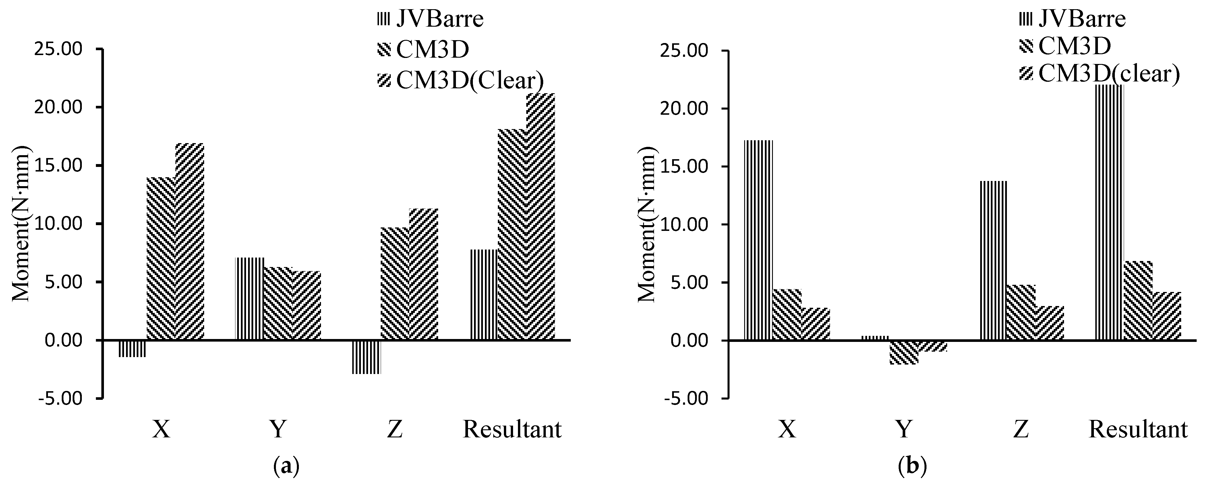
The reaction moments on the canine and molar following each MSD are shown in Figure 4a,b, respectively. The magnitude of the tipping moment on the canine about the X direction induced by the JVB was 12.52 N·mm (90%) and 15.50 N·mm (92%) less than the ones by the CM3D and CM3D Clear, which were 14.0 N·mm and 16.9 N·mm, respectively. Nevertheless, the tipping moment on the canine induced by the JVB was in the opposite direction of that induced by the CM3D and CM3D Clear. The magnitude of the rotational moment about the Z direction induced by the JVB was 6.78 N·mm (70%) and 8.40 N·mm (74%) less than the ones induced by the CM3D and CM3D Clear, which were 9.7 N·mm and 11.3 N·mm in the opposite direction. The buccal-lingual moment on the canine about the Y direction induced by the JVB and CM3Ds was kept at the same level at about 6.0 N·mm to 7.0 N·mm. On the molar, the tipping moment about the X direction induced by the JVB was 12.83 N·mm (290%) and 14.46 N·mm (326%) more than the ones by the CM3D and CM3D Clear, which were 4.42 N·mm and 3.80 N·mm. The rotational moment on the molar about the Z direction induced by the JVB was 8.98 N·mm (187%) and 10.8 N·mm (366%) higher than the ones by the CM3D and CM3D Clear, which were 4.79 N·mm and 2.95 N·mm. The magnitude of the buccal-lingual moment on the molar induced on all MSDs was negligible, even though the direction of moment by the JVB was opposite to others. In summary, the JVB induced significantly less tipping and rotational moment on the canine, while significantly higher on the molar, compared with the other two MSDs.
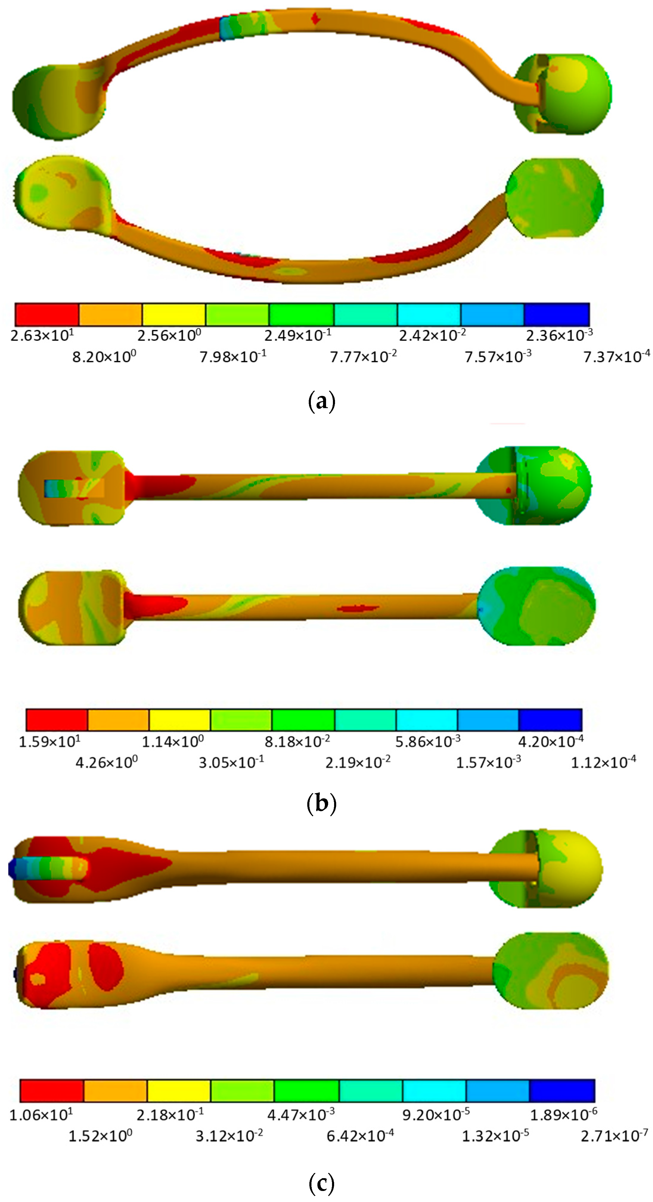
The von-Mises stress distribution in MSDs from the buccal and lingual view is shown in Figure 5. The stress concentration was observed near the hook structure for all MSDs. The area average was taken on the surface of MSDs, which was bonded with the teeth. The area-averaged stress levels on the molar socket of the JVB were 0.46 MPa (460%) and 0.48 MPa (600%) higher than the ones of the CM3D and CM3D Clear on the same part, 0.10 MPa and 0.08 MPa, respectively. The area-averaged stress on the canine pad of the JVB was 0.12 MPa (7.6%) and 0.21 MPa (11.7%) smaller than the ones of the CM3D and CM3D Clear, 1.70 MPa and 1.79 MPa, respectively. In summary, higher stress concentration was observed on the molar socket in the JVB, which was consistent with the higher reaction force and moment on the molar induced by the JVB.

4. Discussion

This work quantified the 3D reaction force and moment on the canine and molar induced by the application of different MSDs by extracting the reaction force and moment on the contact region between the teeth and maxilla. The important reaction forces or moments related to the tooth movement, extrusion, tipping, and rotation were quantified for the canine and molar, the two teeth connected with the MSDs. Three MSDs, the JVB, CM3D, and CM3D Clear, were implemented in this work. A comparative study was conducted to study the influence of the structural design of the MSD on the reaction force and moment induced on each tooth. The results show that the maxillary molar would undertake more force and moment through structural modification of the orthodontic devices, i.e., moving the hook structure from the canine end to the middle of the bar. To the author’s best knowledge, this work is the first-time 3D mechanical characterization of the reaction force and moment for these typical MSDs in Class II malocclusion treatment was conducted. The mechanistic understandings from this work will shed light on the optimal design of the MSDs.
The quantification of the treatment effects of MSDs is essential for an expected tooth movement trend. In this work, the treatment effects of different MSDs in terms of reaction force and moment are quantified. A two-dimensional study by Dr. Voudouris’s group showed that the total resultant extrusion force along the vertical force increased from 3.38 to 4.97 oz by moving the hook structure from the end of the CM3Ds to the middle of the JVB [20]. This work shows that the JVB induced less extrusion force on the canine compared with CM3Ds. Obviously, by changing the location of the hook structure from one end to the middle of the MSD, more load was undertaken by the molar tooth in both force and moment. The JVB induced considerably higher extrusion force on the molar, which was negligible in the CM3Ds. The JVB induced significantly less tipping moment and rotational moment compared with the CM3Ds but significantly higher on the molar. These observations indicate that different portions of force can be allocated to each tooth by changing the location of the hook structure. In addition, we also noticed that the reaction force on the canine along the distal direction showed a negative value compared with the CM3Ds, indicating that the arc structure of the JVB may induce a trend that the molar and canine move farther apart from each other and the canine moves backward when the distance of the molar and canine reaches a certain value. Such a trend is not observed in the other two CM3Ds. The forces on the molar teeth help correct Class II malocclusion by distalizing the molar. In addition, the distal tipping of the mesial cusp may help in Class II correction. However, the extrusive forces and the mesial tipping of the molar may open the bite, which is needed in deep-bite corrections, since it is found commonly in Class II malocclusion [42].
The stress distribution in the MSDs also agreed with the quantified reaction force and moment. The bracket structure of the JVB showed a higher stress than that of the CM3Ds, indicating a higher resultant reaction force on the molar. The minimal stress observed on most parts of the CM3Ds, except on the canine pad, indicated that most of the load was undertaken by the canine. Of notice, with the bar and the bracket connected with a simple pin-point structure, the gap between the bar and the socket may affect force transfer from the hook to the socket and tooth, which will lead to the overestimation of the reaction force. The CM3D Clear was developed with medical-grade polymer for aesthetic purposes, while the structure was softer than the metallic material [40]. Although a minimal difference was observed in this study, it may have a significant effect considering the long-term reaction, especially in terms of tooth movement. The use of a soft material may result in less force transmission from the canine to the molar.
Some limitations exist in the model reconstruction and simulation setup. The premolar was extracted in this model; as a result, the appliances were bonded to the second molar. The conclusion from this work is still held since the force analysis is mainly related to the structural design of the appliances and the relative location between two bonded teeth. In addition, some clinical practices have bonded the JVB with lengths to the premolar or second molar [19]. The mandible and maxilla bone are simulated as rigid bodies to isolate the minimal effect from the surrounding tissues. The simulation technique is thereby feasible for the static force analysis to determine the load allocation on the bonded teeth immediately following implantation of the appliances but not feasible for the simulation of the long-term tooth movement. A more realistic material property will lead to more precise results in the stress distribution on the neighbor teeth and the mechanics of tooth–maxilla interaction [43]. These simplifications have minimal effects on our observations since we only focused on the reaction force induced by the MSDs rather than the details of stress/strain distribution on the bone or teeth. The applied forces from elastic, 8.0 oz or 6.5 oz, are from the product label, which may change for a varied stretch due to patient-specific dimensions and daily activities [20]. The interaction between the canine and molar and the neighbor teeth was neglected since little load transfers to the neighbor teeth before tooth movement, even for a deformable maxilla. The periodontal ligament, a softer and thinner tissue surrounding the teeth [41,44], was not directly analyzed in this study but it is crucial to be considered in long-term teeth movement simulations. Hence, more detailed segmentation on CBCT imaging is necessary to fulfill the prerequisites of long-term teeth movement FEA. The limitations will be addressed in our future work involving teeth movement. The tooth movement and alveolar bone remodeling are triggered by the reaction forces between the tooth and alveolar bone. This work provided a method for quantifying the reaction forces. In the future, the relationship between the tooth movement and the reaction forces could be determined using computer simulation and validation with published tooth movement data [41,45].

5. Conclusions

In conclusion, this work quantified the 3D reaction force and moment on the canine and molar induced by the application of different MSDs. The important reaction forces or moments related to the tooth movement, extrusion, tipping, and rotation are quantified for the canine and molar, two teeth connected with the MSDs. Three MSDs, the JVB, CM3D, and CM3D Clear, were implemented in this work. The JVB induced less extrusion force, tipping, and rotational moment on the canine, while larger extrusion force, tipping, and rotational moment on the molar, compared with the other two CM3Ds due to the hook structure changes from the end to the middle in the new design of the JVB. The stress distribution on the MSDs also verified the observations. The mechanistic understandings from this work may shed light on the optimal design of MSDs.

Author Contributions

Conceptualization, A.T., J.C.V., T.S.P. and S.P.; methodology, J.W., L.G. and P.D.; formal analysis, J.W. and P.D.; investigation, J.C.V., T.S.P., S.P. and L.G.; resources, A.T., J.C.V., T.S.P. and S.P.; writing, original draft, J.W. and P.D.; writing, review and editing, J.W., L.G. and P.D.; supervision, L.G. and P.D. All authors have read and agreed to the published version of the manuscript.

Funding

This research received no external funding.

Institutional Review Board Statement

Not applicable.

Informed Consent Statement

Not applicable.

Data Availability Statement

Data is contained within the article.

Conflicts of Interest

We would like to declare any potential conflicts of interest that could influence the objectivity, integrity, or impartiality of our research. We confirm that the author, John C. Voudouris, is a researcher and innovator of the JVBarre used in this study. However, we would like to emphasize that this fact does not affect the objectivity, impartiality, or reliability of the study’s findings. The rest of the authors declare that they have no conflict of interest to disclose.

Correction Statement

This article has been republished with a minor correction to the readability of Figure 4. This change does not affect the scientific content of the article.

References

  1. Prabhakar, R.R. Prevalence of Malocclusion and Need for Early Orthodontic Treatment in Children. JCDR 2014, 8, ZC60–ZC61. [Google Scholar] [CrossRef] [PubMed]
  2. Bilgic, F.; Gelgor, I.E.; Celebi, A.A. Malocclusion Prevalence and Orthodontic Treatment Need in Central Anatolian Adolescents Compared to Euro-pean and Other Nations’ Adolescents. Dent. Press J. Orthod. 2015, 20, 75–81. [Google Scholar] [CrossRef] [PubMed]
  3. Papadopoulos, M.A. (Ed.) Orthodontic Treatment of the Class II Noncompliant Patient: Current Principles and Techniques; Mosby: Edinburgh, Scotland; New York, NY, USA, 2006; ISBN 978-0-7234-3391-0. [Google Scholar]
  4. Papadopoulos, M.A. Orthodontic Treatment of Class II Malocclusion with Miniscrew Implants. Am. J. Orthod. Dentofac. Orthop. 2008, 134, 604.e1–604.e16. [Google Scholar] [CrossRef] [PubMed]
  5. Class II Elastics and Skeletal Anchorage. Available online: https://www.jco-online.com/archive/2018/04/227-case-report-combining-skeletal-anchorage-and-intermaxillary-elastics-in-class-ii-treatment/ (accessed on 3 April 2023).
  6. Al-Anezi, S.A. Class II Malocclusion Treatment Using Combined Twin Block and Fixed Orthodontic Appliances—A Case Report. Saudi Dent. J. 2011, 23, 43–51. [Google Scholar] [CrossRef]
  7. Francisconi, M.F.; Henriques, J.F.C.; Janson, G.; de Freitas, K.M.S.; dos Santos, P.B.D. Stability of Class II Treatment with the Bionator Followed by Fixed Appliances. J. Appl. Oral Sci. 2013, 21, 547–553. [Google Scholar] [CrossRef]
  8. Arvind, P.; Jain, R.K. Skeletally Anchored Forsus Fatigue Resistant Device for Correction of Class II Malocclusions—A Systematic Review and Meta-Analysis. Orthod. Craniofacial Res. 2021, 24, 52–61. [Google Scholar] [CrossRef]
  9. Thukral, R.; Gupta, A. Invisalign: Invisible Orthodontic Treatment—A Review. J. Adv. Med. Dent. Sci. Res. 2015, 3, S42. [Google Scholar]
  10. Weir, T. Clear Aligners in Orthodontic Treatment. Aust. Dent. J. 2017, 62, 58–62. [Google Scholar] [CrossRef]
  11. Ke, Y.; Zhu, Y.; Zhu, M. A Comparison of Treatment Effectiveness between Clear Aligner and Fixed Appliance Therapies. BMC Oral Health 2019, 19, 24. [Google Scholar] [CrossRef]
  12. Verma, P.; George, A.M. Efficacy of Clear Aligners in Producing Molar Distalization: Systematic Review. APOS Trends Orthod. 2022, 11, 317–324. [Google Scholar] [CrossRef]
  13. Lombardo, L.; Cremonini, F.; Oliverio, T.; Cervinara, F.; Siciliani, G. Class II Correction with Carriere Motion 3D Appliance and Clear Aligner Therapy. J. Clin. Orthod. 2022, 56, 187–193. [Google Scholar]
  14. Gou, Y.; Ungvijanpunya, N.; Chen, L.; Zeng, Y.; Ye, H.; Cao, L. Clear Aligner vs Fixed Self-Ligating Appliances: Orthodontic Emergency during the 2020 Coronavirus Disease 2019 Pandemic. Am. J. Orthod. Dentofac. Orthop. 2022, 161, e400–e406. [Google Scholar] [CrossRef] [PubMed]
  15. Kim-Berman, H.; McNamara, J.A.; Lints, J.P.; McMullen, C.; Franchi, L. Treatment effects of the Carriere® Motion 3D™ Appliance for the Correction of Class II Malocclusion in Adolescents. Angle Orthod. 2019, 89, 839–846. [Google Scholar] [CrossRef] [PubMed]
  16. Montasser, M.A.; Scribante, A. Root Injury During Interradicular Insertion is the most Common Complication Associated with Orthodontic Miniscrews. J. Evid. -Based Dent. Pr. 2022, 22, 101688. [Google Scholar] [CrossRef] [PubMed]
  17. Xin, Y.; Wu, Y.; Chen, C.; Wang, C.; Zhao, L. Miniscrews for Orthodontic Anchorage: Analysis of Risk Factors Correlated with the Progressive Susceptibility to Failure. Am. J. Orthod. Dentofac. Orthop. 2022, 162, e192–e202. [Google Scholar] [CrossRef] [PubMed]
  18. Ramírez-Ossa, D.M.; Escobar-Correa, N.; Ramírez-Bustamante, M.A.; Agudelo-Suárez, A.A. An Umbrella Review of the Effectiveness of Temporary Anchorage Devices and the Factors That Contribute to Their Success or Failure. J. Evid. -Based Dent. Pr. 2020, 20, 101402. [Google Scholar] [CrossRef] [PubMed]
  19. Voudouris, D.J.C.; Voudouris, J.D. New JVBarre Maxillary Segmental Distaliser and BiTurbo2 System for Greater Aesthetics, Effective and Efficient Skeletal Class II Treatment: Control of Canine Over-Extrusion and Bodily Maxillary Molar Distalisation. Ortho Int. Mag. Orthod. 2019, 4, 14–19. [Google Scholar]
  20. Voudouris, J.C.; Voudouris, J.D.; Nicolay, O.; Glaser, B.; Nicozisis, J.; Theodoridis, G.; Carrillo, R.; Moshiri, M.; Masoud, M. Clear Aligners, Dentofacial Orthopedics, Physics and Supercorrection Prescription Biomechanics. A Meeting of the Minds. Semin. Orthod. 2022, 27, 202–258. [Google Scholar] [CrossRef]
  21. Nihara, J.; Gielo-Perczak, K.; Cardinal, L.; Saito, I.; Nanda, R.; Uribe, F. Finite element analysis of mandibular molar protraction mechanics using miniscrews. Eur. J. Orthod. 2014, 37, 95–100. [Google Scholar] [CrossRef]
  22. Çifter, M.; Saraç, M. Maxillary Posterior Intrusion Mechanics with Mini-Implant Anchorage Evaluated with the Finite Element Method. Am. J. Orthod. Dentofac. Orthop. 2011, 140, e233–e241. [Google Scholar] [CrossRef]
  23. Fiorillo, L.; Cicciù, M.; D’amico, C.; Mauceri, R.; Oteri, G.; Cervino, G. Finite Element Method and Von Mises Investigation on Bone Response to Dynamic Stress with a Novel Conical Dental Implant Connection. BioMed Res. Int. 2020, 2020, 2976067. [Google Scholar] [CrossRef] [PubMed]
  24. Fiorillo, L.; Milone, D.; D’andrea, D.; Santonocito, D.; Risitano, G.; Cervino, G.; Cicciù, M. Finite Element Analysis of Zirconia Dental Implant. Prosthesis 2022, 4, 490–499. [Google Scholar] [CrossRef]
  25. Cicciu, M.; Bramanti, E.; Matacena, G.; Guglielmino, E.; Risitano, G. FEM Evaluation of Cemented-Retained Versus Screw-Retained Dental Implant Single-Tooth Crown Prosthesis. Int. J. Clin. Exp. Med. 2014, 7, 817–825. [Google Scholar] [PubMed]
  26. Tominaga, J.-Y.; Ozaki, H.; Chiang, P.-C.; Sumi, M.; Tanaka, M.; Koga, Y.; Bourauel, C.; Yoshida, N. Effect of Bracket Slot and Archwire Dimensions on Anterior Tooth Movement During Space Closure in Sliding Mechanics: A 3-Dimensional Finite Element Study. Am. J. Orthod. Dentofac. Orthop. 2014, 146, 166–174. [Google Scholar] [CrossRef] [PubMed]
  27. Jayade, V.; Annigeri, S.; Jayade, C.; Thawani, P. Biomechanics of Torque from Twisted Rectangular Archwires: A Finite Element Investigation. Angle Orthod. 2007, 77, 214–220. [Google Scholar] [CrossRef] [PubMed]
  28. Chang, Y.-I.; Shin, S.-J.; Baek, S.-H. Three-Dimensional Finite Element Analysis in Distal En Masse Movement of the Maxillary Dentition with the Multiloop Edgewise Archwire. Eur. J. Orthod. 2004, 26, 339–345. [Google Scholar] [CrossRef]
  29. Jiang, T.; Wu, R.Y.; Wang, J.K.; Wang, H.H.; Tang, G.H. Clear Aligners for Maxillary Anterior En Masse Retraction: A 3D Finite Element Study. Sci. Rep. 2020, 10, 10156. [Google Scholar] [CrossRef]
  30. Rossini, G.; Schiaffino, M.; Parrini, S.; Sedran, A.; Deregibus, A.; Castroflorio, T. Upper Second Molar Distalization with Clear Aligners: A Finite Element Study. Appl. Sci. 2020, 10, 7739. [Google Scholar] [CrossRef]
  31. Park, J.-C.; Shin, H.-S.; Cha, J.-Y.; Park, J.-T. A three-Dimensional Finite Element Analysis of the Relationship between Masticatory Performance and Skeletal Malocclusion. J. Periodontal Implant Sci. 2015, 45, 8–13. [Google Scholar] [CrossRef]
  32. Xie, Q.; Li, D. The Cross-Sectional Effects of Ribbon Arch Wires on Class II Malocclusion Intermaxillary Traction: A Three-Dimensional Finite Element Analysis. BMC Oral Health 2021, 21, 501. [Google Scholar] [CrossRef]
  33. Kawamura, J.; Park, J.H.; Kojima, Y.; Kook, Y.; Kyung, H.; Chae, J. Biomechanical Analysis for Total Mesialization of the Mandibular Dentition: A Finite Element Study. Orthod. Craniofac. Res. 2019, 22, 329–336. [Google Scholar] [CrossRef] [PubMed]
  34. Chaudhry, A.; Sidhu, M.S.; Chaudhary, G.; Grover, S.; Chaudhry, N.; Kaushik, A. Evaluation of Stress Changes in the Mandible with a Fixed Functional Appliance: A Finite Element Study. Am. J. Orthod. Dentofac. Orthop. 2015, 147, 226–234. [Google Scholar] [CrossRef] [PubMed]
  35. Al Hamdany, A.K.; Hasan, L.A.; Alrawi, M.N.A.; Alhajar, E.H.K. PowerScope 2 Functional Appliance: A 3D Finite Element Simulation of Its Action on the Mandible. J. Oral Biol. Craniofac. Res. 2023, 13, 299–305. [Google Scholar] [CrossRef]
  36. Zhu, C.; Li, R.; Yuan, L.; Zheng, Y.; Jin, Y.; Li, H.; Liu, C.; Xia, L.; Fang, B. Effects of the Advanced Mandibular Spring on Mandibular Retrognathia Treatment: A Three-Dimensional Finite Element Study. BMC Oral Health 2022, 22, 271. [Google Scholar] [CrossRef] [PubMed]
  37. Wang, Q.; Dai, D.; Wang, J.; Chen, Y.; Zhang, C. Biomechanical Analysis of Effective Mandibular en-Masse Retraction Using Class II Elastics with a Clear Aligner: A Finite Element Study. Prog. Orthod. 2022, 23, 23. [Google Scholar] [CrossRef] [PubMed]
  38. Areepong, D.; Kim, K.B.; Oliver, D.R.; Ueno, H. The Class II Carriere Motion Appliance. Angle Orthod. 2020, 90, 491–499. [Google Scholar] [CrossRef]
  39. Fedorov, A.; Beichel, R.; Kalpathy-Cramer, J.; Finet, J.; Fillion-Robin, J.-C.; Pujol, S.; Bauer, C.; Jennings, D.; Fennessy, F.; Sonka, M.; et al. 3D Slicer as an image computing platform for the Quantitative Imaging Network. Magn. Reson. Imaging 2012, 30, 1323–1341. [Google Scholar] [CrossRef]
  40. SpecialChem Young’s Modulus: Modulus of Elasticity Units & Formula. Available online: https://omnexus.specialchem.com/polymer-properties/properties/young-modulus (accessed on 15 January 2023).
  41. Kojima, Y.; Fukui, H. A Finite Element Simulation of Initial Movement, Orthodontic Movement, and the Centre of Resistance of the Maxillary Teeth Connected with an Archwire. Eur. J. Orthod. 2014, 36, 255–261. [Google Scholar] [CrossRef]
  42. Ghafari, J.G.; Macari, A.T.; Haddad, R.V. Deep Bite: Treatment Options and Challenges. Semin. Orthod. 2013, 19, 253–266. [Google Scholar] [CrossRef]
  43. Feng, Y.; Kong, W.-D.; Cen, W.-J.; Zhou, X.-Z.; Zhang, W.; Li, Q.-T.; Guo, H.-Y.; Yu, J.-W. Finite Element Analysis of the Effect of Power arm Locations on Tooth Movement in Extraction Space Closure with Miniscrew Anchorage in Customized Lingual Orthodontic Treatment. Am. J. Orthod. Dentofac. Orthop. 2019, 156, 210–219. [Google Scholar] [CrossRef]
  44. Likitmongkolsakul, U.; Smithmaitrie, P.; Samruajbenjakun, B.; Aksornmuang, J. Development and Validation of 3D Finite Element Models for Prediction of Orthodontic Tooth Movement. Int. J. Dent. 2018, 2018, 4927503. [Google Scholar] [CrossRef] [PubMed]
  45. Chen, J.; Li, W.; Swain, M.V.; Darendeliler, M.A.; Li, Q. A Periodontal Ligament Driven Remodeling Algorithm for Orthodontic Tooth Movement. J. Biomech. 2014, 47, 1689–1695. [Google Scholar] [CrossRef] [PubMed]
Figure 1. Process of producing FEA model from CBCT image. (a) Segmentation of CBCT in 3D slicer, including transverse, sagittal, and coronal view of CBCT, and segmented model; (b) model of JVB, CM3D, and CM3D Clear; (c) assembly of JVB with maxilla and teeth in SpaceClaim.
Applsci 13 07195 g001
Figure 2. Three-dimensional model of maxilla and mandible with JVB located between the maxillary molar (UL7) and canine (UL3). In this model, one of the premolars is missing. The load vector () is from the hook of the MSDs to the mandibular molar. For the CM3D, the hook is on the canine side, so was more tilted due to the smaller β.
Applsci 13 07195 g002
Figure 3. Reactive forces on canine (a) and molar (b) with MSDs.
Applsci 13 07195 g003
Figure 4. Reactive moments on canine (a) and molar (b) with MSDs.
Applsci 13 07195 g004
Figure 5. Von-Mises stress of (a) JVB, (b) CM3D, and (c) CM3D Clear in MPa from buccal and lingual view.
Applsci 13 07195 g005
Table 1. Material properties of tooth and MSDs.
Young’s Modulus (GPa)Poisson’s Ratio
Tooth19.60.3
JVB and CM3D2000.3
CM3D Clear30.33
Table 2. Angle forces on hook of MSDs.
αβγ
JVB85.0°50.2°139.8°
CM3D81.0°26.5°114.7°
CM3D Clear81.0°26.5°114.7°
Disclaimer/Publisher’s Note: The statements, opinions and data contained in all publications are solely those of the individual author(s) and contributor(s) and not of MDPI and/or the editor(s). MDPI and/or the editor(s) disclaim responsibility for any injury to people or property resulting from any ideas, methods, instructions or products referred to in the content.