
Design of Pyrolysis Plant for Waste Methyl Ethyl Ketone from the Polarizer Manufacturing Process

Abstract
:1. Introduction
2. Materials and Methods
2.1. Feedstock
2.2. Lab-Scale System
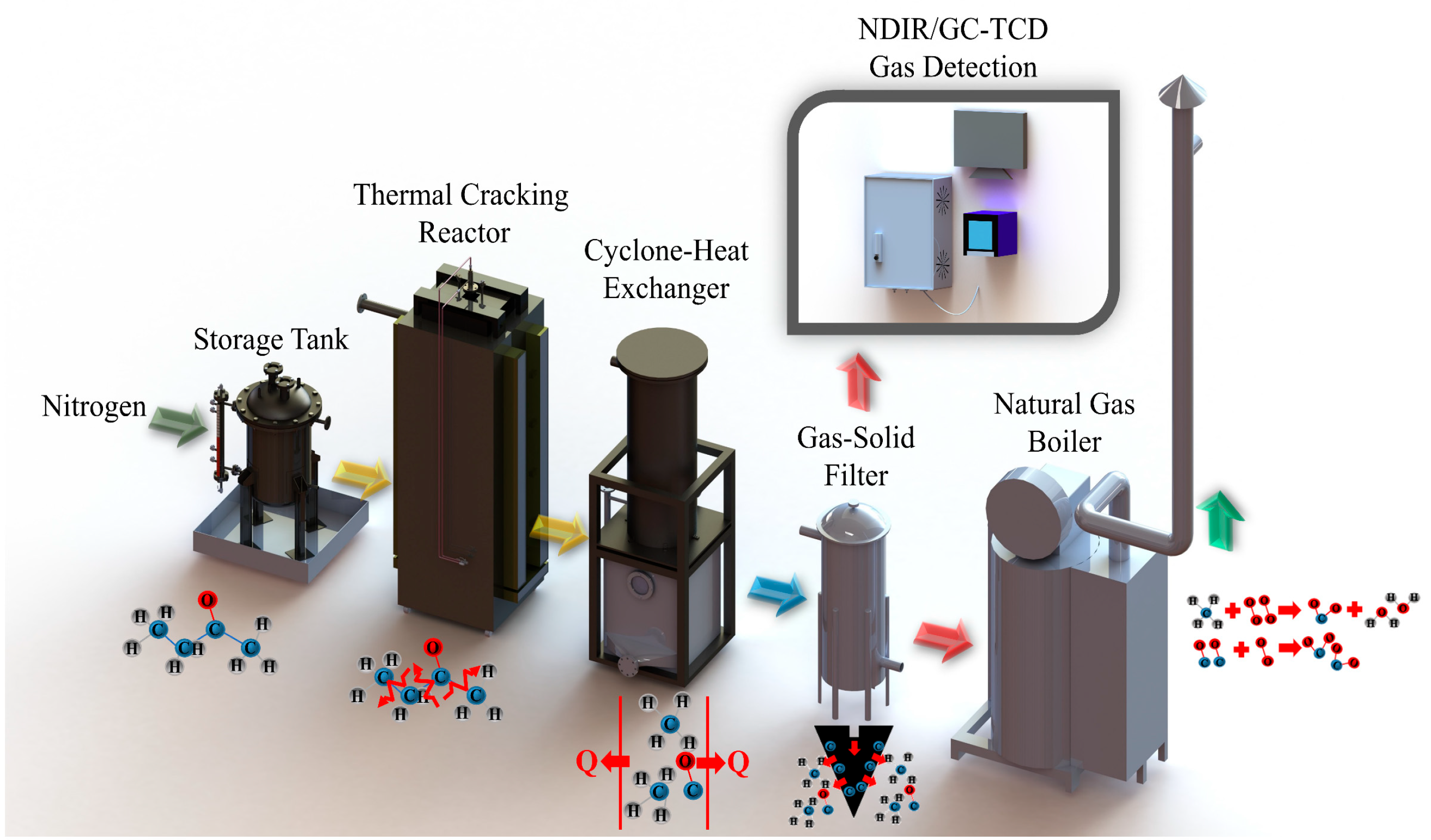
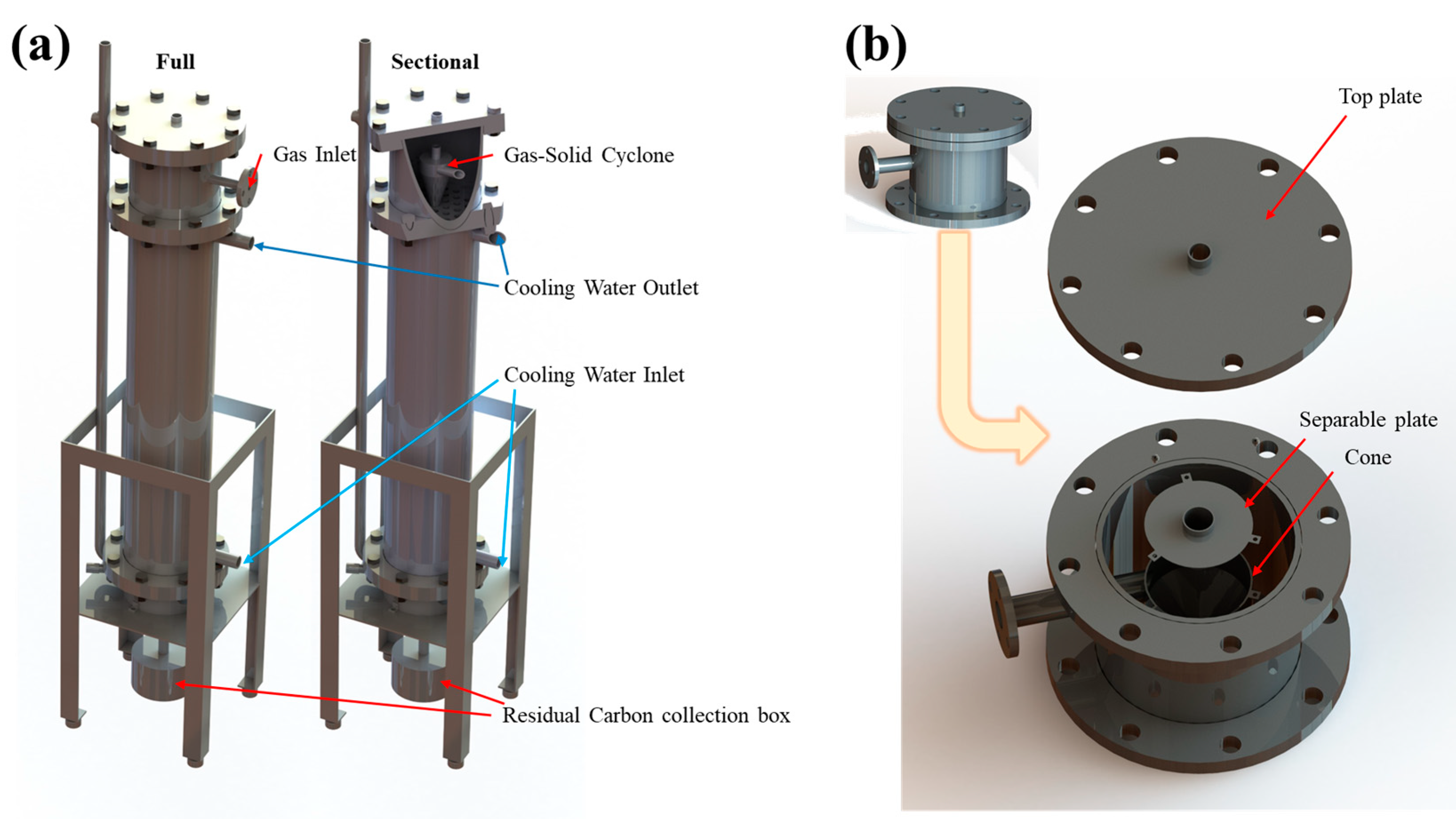
2.3. Field System
2.4. Detection and Computational Detail
3. Results and Discussion
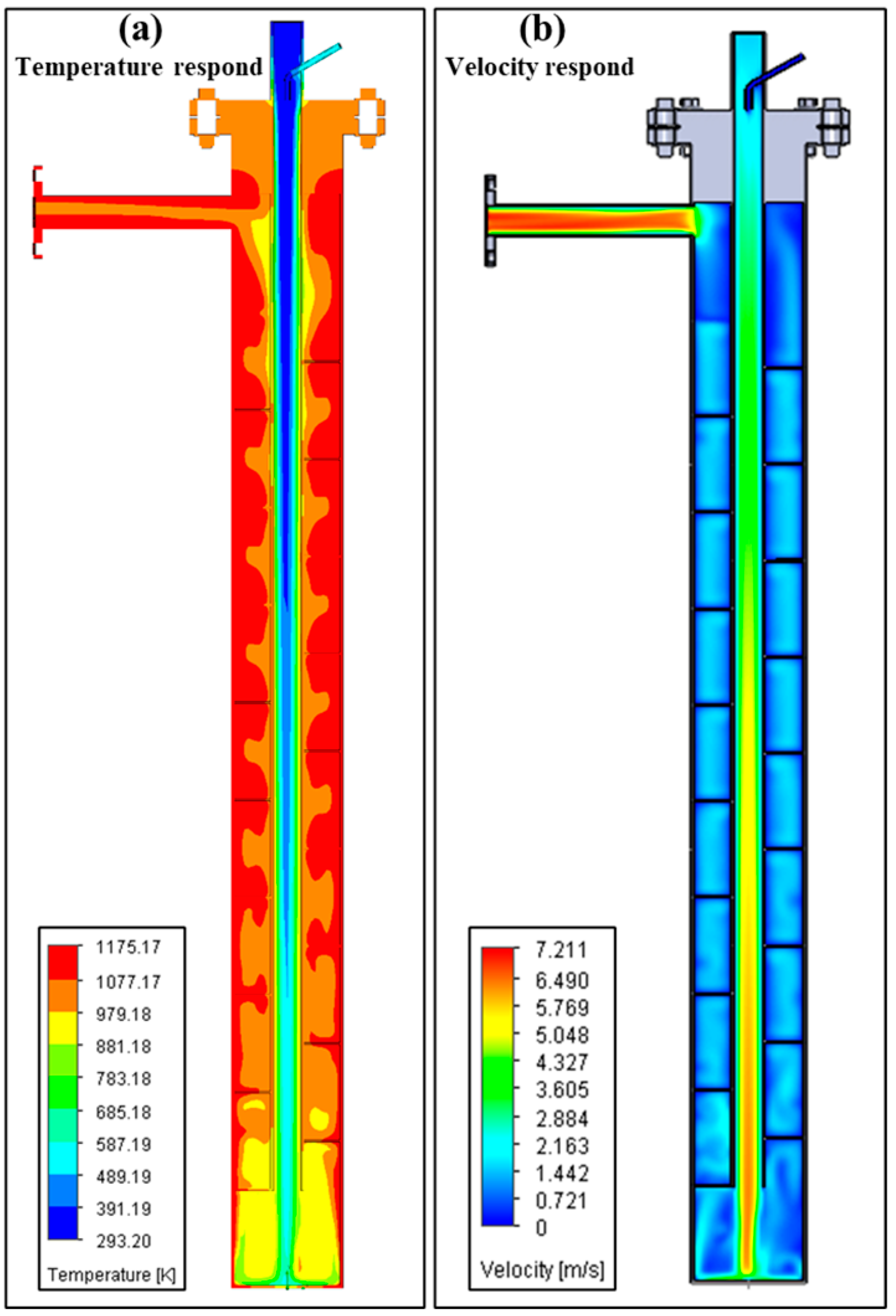
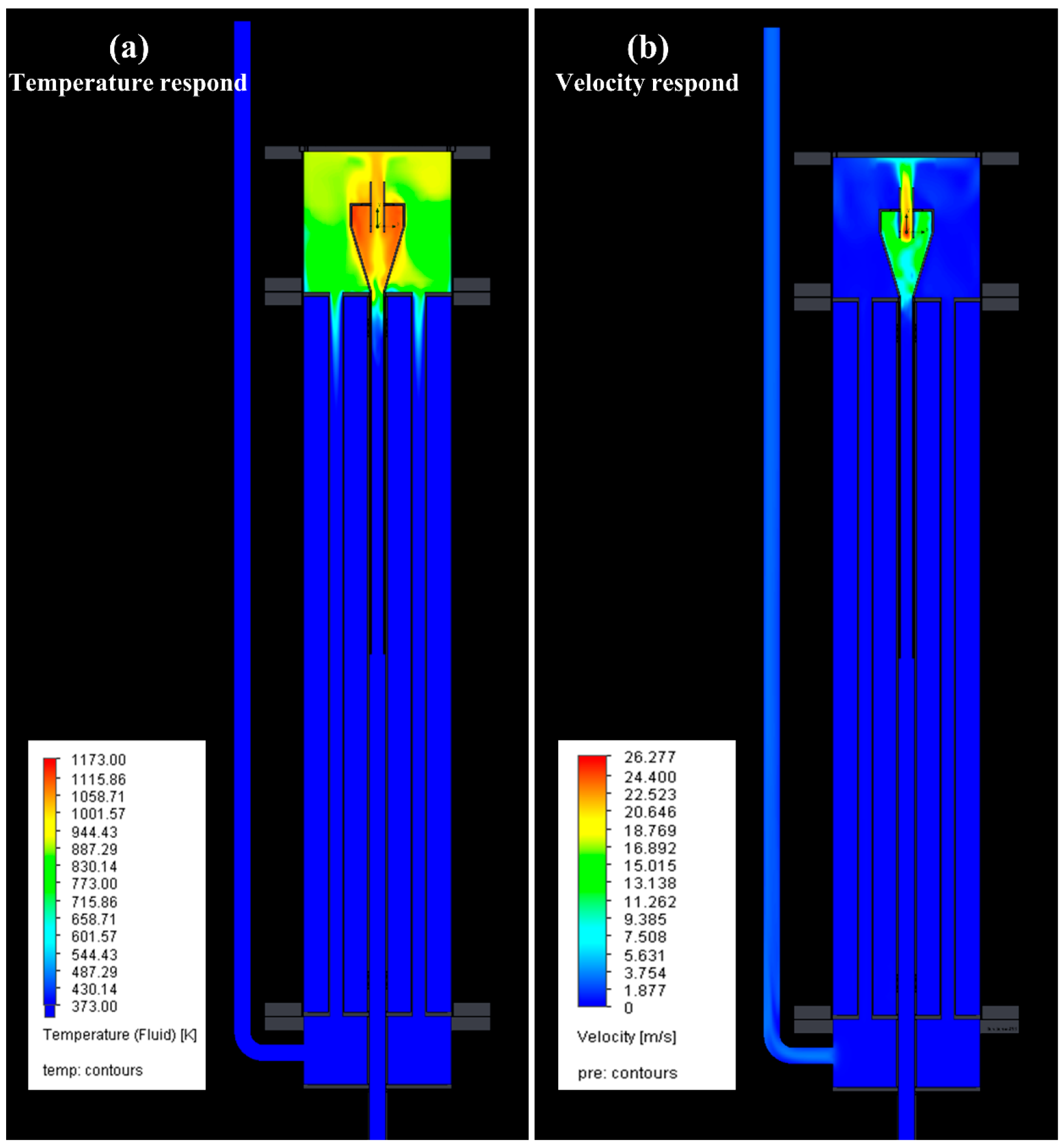
3.1. Model of Lab-Scale System
3.2. Thermal Pyrolysis Result of Lab-Scale System
3.3. Field System
4. Conclusions
5. Patents
Author Contributions
Funding
Informed Consent Statement
Data Availability Statement
Conflicts of Interest
References
- Xu, Y.; He, R.; Jin, F. Overview of the production background and treatment methods of waste photovoltaic modules. In Proceedings of IOP Conference Series: Materials Science and Engineering; IOP Publishing: Bristol, UK, 2018; p. 032105. [Google Scholar]
- Cavanagh, E.J.; Savelski, M.J.; Slater, C.S. Optimization of environmental impact reduction and economic feasibility of solvent waste recovery using a new software tool. Chem. Eng. Res. Des. 2014, 92, 1942–1954. [Google Scholar] [CrossRef]
- Nemeth, B.; Lang, P.; Hegely, L. Optimisation of solvent recovery in two batch distillation columns of different size. J. Clean. Prod. 2020, 275, 122746. [Google Scholar] [CrossRef]
- Rundquist, E.M.; Pink, C.J.; Livingston, A.G. Organic solvent nanofiltration: A potential alternative to distillation for solvent recovery from crystallisation mother liquors. Green Chem. 2012, 14, 2197–2205. [Google Scholar] [CrossRef]
- Lauber, J.D. Burning chemical wastes as fuels in cement kilns. J. Air Pollut. Control Assoc. 1982, 32, 771–777. [Google Scholar] [CrossRef]
- Lee, J.-W.; Yoo, Y.-T. A comparative study on dimensional stability of PET and BOPP substrates for fabrication of flexible electric/electronic devices through roll-to-roll printing. J. Ind. Eng. Chem. 2012, 18, 1647–1653. [Google Scholar] [CrossRef]
- Bailey, W.J.; Cesare, F. Pyrolysis of unsaturated compounds. 2. Pyrolysis of ketones. J. Org. Chem. 1978, 43, 1421–1423. [Google Scholar] [CrossRef]
- McGee, T.H.; Waring, C.E. Kinetics of the thermal decomposition of hexafluoroazomethane and the reaction of trifluoromethyl radicals with methyl ethyl ketone. J. Phys. Chem. 1969, 73, 2838–2845. [Google Scholar] [CrossRef]
- Norrish, R.G.; Appleyard, M.E. 191. Primary photochemical reactions. Part IV. Decomposition of methyl ethyl ketone and methyl butyl ketone. J. Chem. Soc. 1934, 1934, 874–880. [Google Scholar] [CrossRef]
- Waring, C.E.; Mutter, W.E. The kinetics of the thermal decomposition of Gaseous methyl Ethyl Ketone1a. J. Am. Chem. Soc. 1948, 70, 4073–4081. [Google Scholar] [CrossRef]
- Bajus, M.; Hájeková, E. Thermal Cracking of the Model Seven Components Mixed Plastics into Oils/Waxes. Pet. Coal 2010, 52, 164–172. [Google Scholar]
- Barokah, B.; Semin, S.; Cahyono, B.; Sampurno, B. Design of New Fin Baffle Shell and Tube Heat Exchanger for Heating of Biodiesel Fuel Based on Simulation. Int. J. Simul. Syst. Sci. Technol. 2020, 21, 5.1–5.7. [Google Scholar] [CrossRef]
- Mangos, O. Study of the Circulation of Heat Transfer Fluid in the Permanent Magnets Thermo-Generator. In Proceedings of the 2021 International Conference on Electromechanical and Energy Systems (SIELMEN), Iasi, Romania, 6–8 October 2021; pp. 538–542. [Google Scholar]
- Chew, K.W.; Chia, S.R.; Chia, W.Y.; Cheah, W.Y.; Munawaroh, H.S.H.; Ong, W.-J. Abatement of hazardous materials and biomass waste via pyrolysis and co-pyrolysis for environmental sustainability and circular economy. Environ. Pollut. 2021, 278, 116836. [Google Scholar] [CrossRef]
- Martínez, J.D. An overview of the end-of-life tires status in some Latin American countries: Proposing pyrolysis for a circular economy. Renew. Sustain. Energy Rev. 2021, 144, 111032. [Google Scholar] [CrossRef]
- Naqvi, S.; Prabhakara, H.M.; Bramer, E.; Dierkes, W.; Akkerman, R.; Brem, G. A critical review on recycling of end-of-life carbon fibre/glass fibre reinforced composites waste using pyrolysis towards a circular economy. Resour. Conserv. Recycl. 2018, 136, 118–129. [Google Scholar] [CrossRef] [Green Version]
- Sakthipriya, N. Plastic waste management: A road map to achieve circular economy and recent innovations in pyrolysis. Sci. Total Environ. 2022, 809, 151160. [Google Scholar]
- Zabaniotou, A.; Rovas, D.; Libutti, A.; Monteleone, M. Boosting circular economy and closing the loop in agriculture: Case study of a small-scale pyrolysis–biochar based system integrated in an olive farm in symbiosis with an olive mill. Environ. Dev. 2015, 14, 22–36. [Google Scholar] [CrossRef]
- Region, O.H.A. ASHRAE Handbook Fundamentals; ASHRAE Research: Peachtree Corners, Georgia, 2005. [Google Scholar]
- Green, D.W.; Southard, M.Z. Perry’s Chemical Engineers’ Handbook; McGraw-Hill Education: New York, NY, USA, 2019. [Google Scholar]
- Perone, C.; Romaniello, R.; Leone, A.; Catalano, P.; Tamborrino, A. CFD analysis of a tubular heat exchanger for the conditioning of olive paste. Appl. Sci. 2021, 11, 1858. [Google Scholar] [CrossRef]
- Paul, A. Optimization in Thermal Design of Surface Condenser by Changing Tube Material. J. Manuf. Eng. 2012, 7, 171–175. [Google Scholar]
- Waring, C.E.; Spector, M. The mechanism of the thermal decomposition of methyl ethyl ketone. J. Am. Chem. Soc. 1955, 77, 6453–6457. [Google Scholar] [CrossRef]
- Ruiz, M.; Callejas, A.; Millera, A.; Alzueta, M.; Bilbao, R. Soot formation from C2H2 and C2H4 pyrolysis at different temperatures. J. Anal. Appl. Pyrolysis 2007, 79, 244–251. [Google Scholar] [CrossRef]
- Fabry, F.; Flamant, G.; Fulcheri, L. Carbon black processing by thermal plasma. Analysis of the particle formation mechanism. Chem. Eng. Sci. 2001, 56, 2123–2132. [Google Scholar] [CrossRef]
- Sánchez, N.; Callejas, A.; Millera, A.; Bilbao, R.; Alzueta, M. Formation of PAH and soot during acetylene pyrolysis at different gas residence times and reaction temperatures. Energy 2012, 43, 30–36. [Google Scholar] [CrossRef]
- Oh, K.C.; Lee, C.B.; Lee, E.J. Characteristics of soot particles formed by diesel pyrolysis. J. Anal. Appl. Pyrolysis 2011, 92, 456–462. [Google Scholar] [CrossRef]
- Bang, Y.-M.; Cho, C.P.; Jung, Y.; Park, S.-R.; Kim, J.-G.; Park, S. Thermal and flow characteristics of a cylindrical superheated steam generator with helical fins. Energy 2023, 267, 126599. [Google Scholar] [CrossRef]
- Moon, H.M.; Ochi, K.; Kojima, K. Vapor-liquid equilibria for the ethyl methyl ketone+ water system with limited miscibility. J. Chem. Eng. Data 1995, 40, 468–471. [Google Scholar] [CrossRef]
- Wark, K.; Warner, C.; Davis, W. Air Pollution: Its Origin and Control, 3rd ed.; Addison-Wesley Longman, Inc.: Boston, MA, USA, 1998. [Google Scholar]


| Model | Thermal Cracking Unit | Cyclone-Heat Exchanger Unit |
|---|---|---|
| Software | SOLIDWORKS Flow Simulation | SOLIDWORKS Flow Simulation |
| Mesh | Total cells: 1,416,169 | Total cells: 3,341,314 |
| Fluid cells: 628,680 | Fluid cells: 2,171,307 | |
| Solid cells: 787,489 | Solid cells: 1,170,007 | |
| Boundary Conditions | Gas Inlet: 36 g/min @ 298 K | Gas Inlet: 36 g/min @ 1173 K |
| Real Wall: 1173 K | Water Inlet: 30 LPM @ 298 K | |
| Outlet: 1bar @ 298 K | Outlet: 1bar @ 298 K | |
| Materials | Fluid: Syn-gas | Fluid: Methane&H2O |
| Solid: Steel Stainless | Solid: Steel Stainless | |
| Result | Heating Cylinder: | Tube Side: |
| Average Heat Transfer Coefficient: 2.868 W/m2/K | Average Heat Transfer Coefficient: 529.6 W/m2/K | |
| Average Tube Wall Temperature: 1173 K | Average Tube Wall Temperature: 294.5 K | |
| Average Heat Flux: 2522.88 W/m2 | Average Heat Flux: −626.3 W/m2 | |
| Spiral Deflector: | Shell Side: | |
| Average Heat Transfer Coefficient: 4.79 W/m2/K | Average Heat Transfer Coefficient: 493.5 W/m2/K | |
| Average Tube Wall Temperature: 1105 K | Average Tube Wall Temperature: 294.0 K | |
| Average Heat Flux: 2344 W/m2 | Average Heat Flux: 488.3 W/m2 |
| NO | ASPEN EDR Input/Result | Unit | Value |
|---|---|---|---|
| 1 | Mass flow rate | kg/s | HotSide: 0.0036; ColdSide: 0.1657 |
| 2 | Inlet temperature | °C | HotSide: 870; ColdSide: 25 |
| 3 | Heat exchanged | kW | 8.7 |
| 4 | Allowable pressure drop | bar | HotSide: 0.11; ColdSide: 0.2 |
| 5 | Fouling resistance | m2·K/W | HotSide: 0.00035; ColdSide: 0.00035 |
| 6 | TEMA type | -- | B-E m * |
| 7 | Tube OD/Pitch/Pattern | mm | 20.7/29.5/30 Triangular-Unbaffled |
| 8 | Shell ID/OD | mm | 203.2/208.92 |
| 9 | Tube length | mm | 1000 |
| 10 | Number of tubes/Tube passes | -- | 37/1 |
| 11 | Actual/Required area ratio | -- | 0.95 |
| 12 | Film coefficient | W/m2/K | Overall fouled: 16.7 Overall clean: 16.9 |
| Chemical Compound | Inlet (% mol/mol) | Outlet (% mol/mol) | LOD (% mol/mol) | DRE |
|---|---|---|---|---|
| MEK | 57.06 | N.D. | 0.221 | >99.6% |
| CH4 | -- | 31.78 | 0.138 | -- |
| C2H4 | -- | 1.56 | 0.047 | -- |
| C2H6 | -- | N.D. | 0.316 | -- |
| C2H2 | -- | 0.07 | 0.059 | -- |
| C3H8 | -- | N.D. | 0.174 | -- |
| CO | -- | 20.66 | 0.217 | -- |
| CO2 | -- | 0.51 | 0.057 | -- |
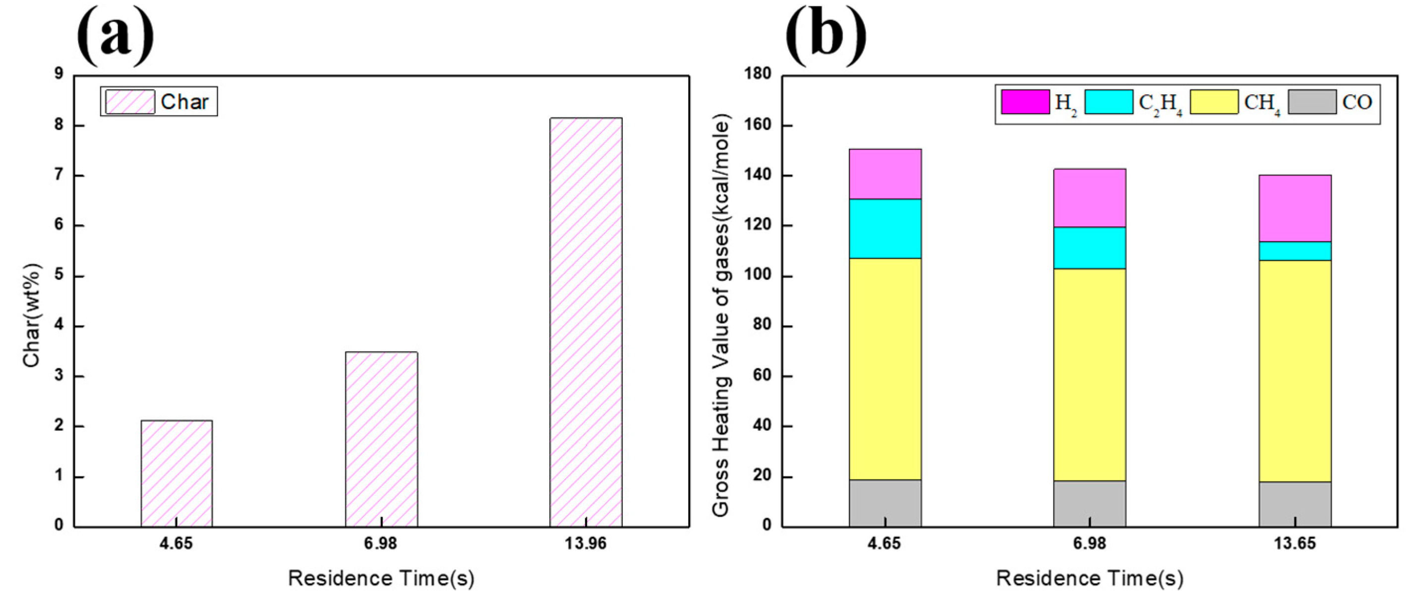
| Case | Temperature (°C) | MEK Flow Rates (mL/min) | N2 Flow Rate (L/min) | Retention Time |
|---|---|---|---|---|
| (a) | 900 | 10 | 0.33 | 13.96 |
| (b) | 900 | 20 | 0.65 | 6.98 |
| (c) | 900 | 30 | 1 | 4.65 |
Disclaimer/Publisher’s Note: The statements, opinions and data contained in all publications are solely those of the individual author(s) and contributor(s) and not of MDPI and/or the editor(s). MDPI and/or the editor(s) disclaim responsibility for any injury to people or property resulting from any ideas, methods, instructions or products referred to in the content. |
© 2023 by the authors. Licensee MDPI, Basel, Switzerland. This article is an open access article distributed under the terms and conditions of the Creative Commons Attribution (CC BY) license (https://creativecommons.org/licenses/by/4.0/).
Share and Cite
Zhang, Y.-Q.; Huang, C.-H.; Wu, C.-Y.; Tseng, Y.-H. Design of Pyrolysis Plant for Waste Methyl Ethyl Ketone from the Polarizer Manufacturing Process. Appl. Sci. 2023, 13, 7362. https://doi.org/10.3390/app13137362
Zhang Y-Q, Huang C-H, Wu C-Y, Tseng Y-H. Design of Pyrolysis Plant for Waste Methyl Ethyl Ketone from the Polarizer Manufacturing Process. Applied Sciences. 2023; 13(13):7362. https://doi.org/10.3390/app13137362
Chicago/Turabian StyleZhang, Yan-Quan, Chih-Hsiang Huang, Chao-Yuan Wu, and Yao-Hsuan Tseng. 2023. "Design of Pyrolysis Plant for Waste Methyl Ethyl Ketone from the Polarizer Manufacturing Process" Applied Sciences 13, no. 13: 7362. https://doi.org/10.3390/app13137362
APA StyleZhang, Y.-Q., Huang, C.-H., Wu, C.-Y., & Tseng, Y.-H. (2023). Design of Pyrolysis Plant for Waste Methyl Ethyl Ketone from the Polarizer Manufacturing Process. Applied Sciences, 13(13), 7362. https://doi.org/10.3390/app13137362